

Page 1
Installation - Parts
®
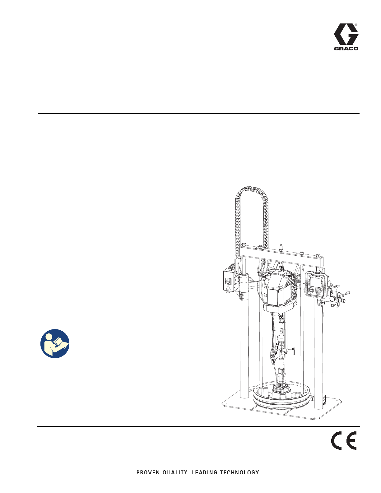
E-Flo
SP
3A6331G
Supply Systems
For transferring or dispensing sealants, adhesives, or other medium to high viscosity
fluids. For professional use only.
Not approved for use in explosive atmospheres or hazardous locations.
D60 3 inch dual post
20 liter (5 gallon), 30 liter (8 gallon),
60 liter (16 gallon) sizes
150 psi (1.0 MPa, 10 bar) Maximum Air Inlet Pressure
EN
D200 3 inch dual post
200 liter (55 gallon) size
150 psi (1.0 MPa, 10 bar) Maximum Air Inlet Pressure
D200S 6.5 inch dual post
200 liter (55 gallon) size
125 psi (0.9 MPa, 9 bar) Maximum Air Inlet Pressure
See page 4 for model information, including maximum
working pressure and approvals.
The Graco Control Architecture Electric Components
are Listed in Intertek’s Directory of Listed Products.
Important Safety Instructions
Read all warnings and instructions in this
manual and in related manuals before
using the equipment. Save all
instructions.
Page 2

Contents
Related Manuals . . . . . . . . . . . . . . . . . . . . . . . . . . . . 3
Models . . . . . . . . . . . . . . . . . . . . . . . . . . . . . . . . . . . . 4
System Pressure . . . . . . . . . . . . . . . . . . . . . . . . . 6
Tandem Ram . . . . . . . . . . . . . . . . . . . . . . . . . . . . 7
Warnings . . . . . . . . . . . . . . . . . . . . . . . . . . . . . . . . . . 8
Component Identification . . . . . . . . . . . . . . . . . . . 11
Typical Installation . . . . . . . . . . . . . . . . . . . . . . . 11
Integrated Air Control Module . . . . . . . . . . . . . . 12
Integrated Air Line Accessories . . . . . . . . . . . . . 12
Advanced Display Module (ADM) . . . . . . . . . . . 13
Platen Component Identification . . . . . . . . . . . . 14
Junction Box Connections . . . . . . . . . . . . . . . . . 15
Installation. . . . . . . . . . . . . . . . . . . . . . . . . . . . . . . . 16
Location . . . . . . . . . . . . . . . . . . . . . . . . . . . . . . . 16
Grounding . . . . . . . . . . . . . . . . . . . . . . . . . . . . . 16
Power Requirements . . . . . . . . . . . . . . . . . . . . . 17
Connect Power . . . . . . . . . . . . . . . . . . . . . . . . . 17
Attach Drum Stops. . . . . . . . . . . . . . . . . . . . . . . 18
Fluid Hose and Air Line Connections. . . . . . . . . 18
Install Vented Oil Cap Before Using Equipment. 18
Setup . . . . . . . . . . . . . . . . . . . . . . . . . . . . . . . . . . . . 19
Wet Cup . . . . . . . . . . . . . . . . . . . . . . . . . . . . . . . 19
Startup . . . . . . . . . . . . . . . . . . . . . . . . . . . . . . . . . . . 20
Flush the Pump . . . . . . . . . . . . . . . . . . . . . . . . . 20
Start and Adjust the Ram. . . . . . . . . . . . . . . . . . 21
Start and Adjust the Pump . . . . . . . . . . . . . . . . . 21
Pressure Relief Procedure. . . . . . . . . . . . . . . . . . . 22
Shutdown and Care of the Pump . . . . . . . . . . . . . 23
Change Drums. . . . . . . . . . . . . . . . . . . . . . . . . . 23
Maintenance . . . . . . . . . . . . . . . . . . . . . . . . . . . . . . 24
Driver Maintenance . . . . . . . . . . . . . . . . . . . . . . 24
Platen Maintenance . . . . . . . . . . . . . . . . . . . . . . 25
Troubleshooting . . . . . . . . . . . . . . . . . . . . . . . . . . . 29
Repair . . . . . . . . . . . . . . . . . . . . . . . . . . . . . . . . . . . 30
Disconnect Pump from Platen . . . . . . . . . . . . . . 30
Connect Platen . . . . . . . . . . . . . . . . . . . . . . . . . 31
Remove Wipers . . . . . . . . . . . . . . . . . . . . . . . . . 31
Install Wipers . . . . . . . . . . . . . . . . . . . . . . . . . . . 31
Remove Displacement Pump. . . . . . . . . . . . . . . 31
Install Displacement Pump . . . . . . . . . . . . . . . . 32
Remove Driver . . . . . . . . . . . . . . . . . . . . . . . . . . 33
Install Driver . . . . . . . . . . . . . . . . . . . . . . . . . . . . 34
Supply Unit Repair . . . . . . . . . . . . . . . . . . . . . . . 34
Parts . . . . . . . . . . . . . . . . . . . . . . . . . . . . . . . . . . . . . 38
D200s 6.5 in. Supply Units . . . . . . . . . . . . . . . . . 38
D200 3 in. Supply Units . . . . . . . . . . . . . . . . . . . 40
D60 3 in. Supply Units . . . . . . . . . . . . . . . . . . . . 42
D200s and D200 Pump Mounts for 55 Gallon (200
Liter) Platen . . . . . . . . . . . . . . . . . . . . . . . . . 44
D60 Pump Mount 257624 for 5 Gallon (20 Liter)
Platen. . . . . . . . . . . . . . . . . . . . . . . . . . . . . . 45
Transformer . . . . . . . . . . . . . . . . . . . . . . . . . . . . 46
Cable Track . . . . . . . . . . . . . . . . . . . . . . . . . . . . 48
55 Gallon Platen . . . . . . . . . . . . . . . . . . . . . . . . . 49
20 Liter (5 Gallon), 30 Liter (8 Gallon), and 60 Liter
(16 Gallon) Platens . . . . . . . . . . . . . . . . . . . 50
Kits and Accessories . . . . . . . . . . . . . . . . . . . . . . . 55
Drum Roller Kits for D200 and D200S Supply Units,
255627 . . . . . . . . . . . . . . . . . . . . . . . . . . . . . 55
Drum Position Clamp Set for D200 Supply Units,
206537 . . . . . . . . . . . . . . . . . . . . . . . . . . . . . 55
Drum Position Clamp for D200S Supply Units . . 55
Enclosed Wet Cup Recirculation Kit. . . . . . . . . . 55
200 Liter (55 Gallon) Platen Cover Kits, 255691 55
Light Tower Kit, 255468 . . . . . . . . . . . . . . . . . . . 55
ADM Kit, 25E437 . . . . . . . . . . . . . . . . . . . . . . . . 55
CAN Cables . . . . . . . . . . . . . . . . . . . . . . . . . . . . 55
I/O Cable, 122029 . . . . . . . . . . . . . . . . . . . . . . . 55
Communication Gateway Module (CGM) Kits . . 56
Low Level Sensor Kit, 25E447 . . . . . . . . . . . . . . 58
Tandem Connection Kit, 25E595 . . . . . . . . . . . . 59
Tandem Depressurization/Recirculation Kit, 25E618
(carbon steel), 25E619 (stainless steel). . . . 60
Tandem Fluid Filter Kit, 25E620 . . . . . . . . . . . . . 64
Dimensions . . . . . . . . . . . . . . . . . . . . . . . . . . . . . . . 67
Dimensions. . . . . . . . . . . . . . . . . . . . . . . . . . . . . 68
Pump Performance . . . . . . . . . . . . . . . . . . . . . . . . . 69
E-Flo SP Performance Charts . . . . . . . . . . . . . . 70
Technical Specifications . . . . . . . . . . . . . . . . . . . . 76
California Proposition 65 . . . . . . . . . . . . . . . . . . . . 77
Graco Standard Warranty . . . . . . . . . . . . . . . . . . . 78
Graco Information 78
2 3A6331G
Page 3

Related Manuals
Manual Description
3A6586
3A6724 E-Flo SP Software Instructions
313526 Supply Systems Operation
E-Flo SP Electric Pump Instructions Parts
Related Manuals
312375
311827
311825
311717
312889
312467
312468
312469
312470
312374 Air Controls Instructions-Parts
312491 Pump Fluid Purge Kit Instructions - Parts
312492 Drum Roller Kit Instructions
312493 Light Tower Kit Instructions
312494
406681 Platen Cover Kit
Check-Mate® Displacement Pumps
Instructions-Parts
™
Dura-Flo
180cc, 220cc, 290cc) Instructions-Parts
Dura-Flo
580cc) Instructions-Parts
Carbon Steel Displacement Pump
(1000cc) Instructions-Parts
60 cc Check-Mate Displacement Pump
Repair Parts
100 cc Check-Mate Displacement Pump
Repair Parts
200 cc Check-Mate Displacement Pump
Repair Parts
250 cc Check-Mate Displacement Pump
Repair Parts
500 cc Check-Mate Displacement Pump
Repair Parts
Enclosed Wetcup Recirculation Kit
Instructions - Parts
Displacement Pumps (145cc,
™
Displacement Pumps (430cc,
334048 EPDM Hose Wiper Kit Instructions - Parts
3A6321
3A6482
3A6331G 3
ADM Token In-System Programming
Instructions
APD20 Advanced Precision Driver
Instructions
Page 4

Models
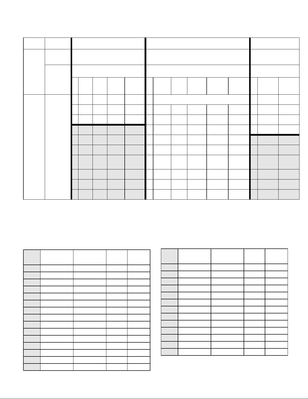
Models
Check the identification plate (ID) for the 7-digit part number of the supply system. Use the following matrix to define
the construction of the supply system, based on the seven digits. For example, Part No. EMC1121 represents an
electric supply system (EM), a carbon steel Check-Mate 100 Severe Duty displacement pump with an electric driver
(C1), a 3 in. dual post ram with integrated air controls (1), a 5-gallon platen with a nitrile seal (2), and 240 VAC power
(1).
NOTICE
To prevent damage to DataTrak soft key buttons, do
not press the buttons with sharp objects such as pens,
plastic cards, or fingernails.
NOTE: Systems with the EMD as the first and second digits are Dura-Flo supply systems.
The digits in the matrix on the next page do not correspond to the Ref. Nos. in the Parts drawings and lists.
4 3A6331G
Page 5
Models
EM C1 1
First
and
Second
Digit
EM
(Electric
Supply
System)
Third and
Fourth
Digit Fifth Digit
Ram Options
Pump
Code
(See Table
1: for 2-digit
Check-Mate
Pump
Code)
(See Table
1: for 2-digit
Dura-Flo
Pump
Code)
Size Style
1 3 in. D60
2 3 in. D200
3 6.5 in. D200s
21
Sixth Digit Seventh Digit
Platen and Seal Options
Drum
Size
20 L
(5 Gal) INT 1 No Platen 1 None 240 VAC
200 L
(55 Gal) INT 2
200 L
(55 Gal) INT 3
Air
Controls
Platen
(5 Gal) F, SW CS Nitrile D60 2 None 480 VAC
(5 Gal) F, SW CS
4
(5 Gal) F, DW CS Nitrile D60 4 ADM 480 VAC
5
(5 Gal) F, DW CS
6
(5 Gal) F, SW SS
200 L
7
(55 Gal) DR
200 L
8
(55 Gal) DR AL EPDM
200 L
9
(55 Gal) DR AL Neoprene
200 L
A
(55 Gal) DR AL
Size
20 L
20 L
20 L
20 L
20 L
Platen
Style
Platen
Material
PTFE
Coated
AL EPDM
Seal
Material
Polyure-
thane D60 3 ADM 240 VAC
Polyure-
thane D60
PTFE
coated D60
EPDM
Hose
Ram
Compati-
bility Interface Power
D200,
D200s
D200,
D200s
D200,
D200s
D200,
D200s
Interface and Power
Options
KEY:
INT = Integrated air controls SW = Single wiper CS = Carbon Steel Severe Duty
F = Flat DW = Double wiper SS = Stainless Steel Severe Duty SM = Stainless Steel MaxLife
DR = Dual o-ring AL = Aluminum
CM = Carbon Steel MaxLife
Table 1: Pump Code Index
Pump
Code Part No. Pump Type
Pump
Size
Pump
Material
C1 EC100CS1 Check-Mate 100cc CS
C2 EC100CM1 Check-Mate 100cc CM
C3 EC100SS1 Check-Mate 100cc SS
C4 EC100SM1 Check-Mate 100cc SM
C5 EC200CS1 Check-Mate 200cc CS
C6 EC200CM1 Check-Mate 200cc CM
C7 EC200SS1 Check-Mate 200cc SS
C8 EC200SM1 Check-Mate 200cc SM
C9 EC250CS1 Check-Mate 250cc CS
CA EC250CM1 Check-Mate 250cc CM
CB EC250SS1 Check-Mate 250cc SS
CC EC250SM1 Check-Mate 250cc SM
CD EC500CS1 Check-Mate 500cc CS
CE EC500CM1 Check-Mate 500cc CM
CF EC500SS1 Check-Mate 500cc SS
Pump
Code Part No. Pump Type
CG EC500SM1 Check-Mate 500cc SM
D1 ED115CS1 Dura-Flo 115cc CS
D2 ED145CS1 Dura-Flo 145cc CS
D3 ED145SS1 Dura-Flo 145cc SS
D4 ED180CS1 Dura-Flo 180cc CS
D5 ED180SS1 Dura-Flo 180cc SS
D6 ED220CS1 Dura-Flo 220cc CS
D7 ED220SS1 Dura-Flo 220cc SS
D8 ED290CS1 Dura-Flo 290cc CS
D9 ED290SS1 Dura-Flo 290cc SS
DA ED430CS1 Dura-Flo 430cc CS
DB ED430SS1 Dura-Flo 430cc SS
DC ED430SM1 Dura-Flo 430cc SM
NOTE: See the E-Flo SP Electric Pump Instructions-Parts
manual for a complete parts list.
Pump
Size
Pump
Material
®
3A6331G 5
Page 6

Models
System Pressure
Due to factors such as the dispensing system design,
the material being pumped, and the flow rate, the
dynamic pressure will not reach the rated working (stall)
pressure of the system.
Pump Working (Stall) Pressure Max Dynamic (Run) Pressure
Lower Size psi bar MPa psi bar MPa
100CS/CM/SS/SM
200CS/CM/SS/SM
250CS/CM/SS/SM
500CS/CM/SS/SM
Check-Mate
145SS
180SS
220SS
290SS
430CS/SS/SM
115CS
Dura-Flow
145CS
180CS
220CS
290CS
6,000 414 41.4 6,000 414 41.4
4,200 290 29.0 3,905 269 26.9
3,400 234 23.4 3,122 215 21.5
1,600 110 11.0 1,487 103 10.3
5,600 386 38.6 5,204 359 35.9
4,500 310 31.0 4,164 287 28.7
3,700 255 25.5 3,470 239 23.9
2,800 193 19.3 2,602 179 17.9
1,900 131 13.1 1,735 120 12.0
6,000 414 41.4 6,000 414 41.4
5,600 386 38.6 5,204 359 35.9
4,500 310 31.0 4,164 287 28.7
3,700 255 25.5 3,472 239 23.9
2,800 193 19.3 2,602 179 17.9
Flow Rate Table
Lower Size
100CS/CM/SS/SM
200CS/CM/SS/SM
250CS/CM/SS/SM
500CS/CM/SS/SM
Check-Mate
145SS
180SS
220SS
290SS
430CS/SS/SM
115CS
Dura-Flow
145CS
180CS
220CS
290CS
Flow Rate
(cc/min)
2,500 0.66 1 in. NPT female
5,000 1.32 1 in. NPT female
6,250 1.65 1 in. NPT female
12,500 3.30 1-1/2 in. NPT female
3,625 0.96 1 in. NPT female
4,500 1.19 1 in. NPT female
5,500 1.45 1 in. NPT female
7,250 1.92 1 in. NPT female
10,750 2.84 1-1/2 in. NPT female
2,875 0.76 1 in. NPT female
3,625 0.96 1 in. NPT female
4,500 1.19 1 in. NPT female
5,500 1.45 1 in. NPT female
7,250 1.92 1 in. NPT female
Flow Rate
(gpm) Outlet Fitting Size
6 3A6331G
Page 7

Tandem Ram
Models
How to Buy
1. Configure Tandem Ram “A” - E-Flo SP Ram with an
ADM (Quantity 1 per Tandem System).
- Example: EMC1283 – D200 Ram, Electric
Pump with Check-Mate 100 CS Lower, 200L
EPDM Platen, 240V, with ADM.
2. Configure Tandem Ram “B” - E-Flo SP Ram without
an ADM (Quantity 1 per Tandem System).
- Example: EMC1281 – D200 Ram, Electric
Pump with Check-Mate 100 CS Lower, 200L
EPDM Platen, 240V, without ADM.
3. Purchase Tandem Connection Kit, 25E595
(Quantity 1 per Tandem System).
4. Purchase Accessories.
- Depressurization/Recirculation Kit (Quantity 1
per Ram)
25E618: for Carbon Steel Pump Lowers
25E619: for Stainless Steel Pump Lowers
5. Purchase hoses for the system.
- For Check-Mate Pumps:
Pump Lower
Size
100cc 6000 psi
200cc 4200 psi
250cc 3400 psi
500cc 1600 psi
- For Dura-Flo Pumps:
Pump Lower
Size
115cc 6000 psi
145cc 5600 psi
180cc 4500 psi
220cc 3700 psi
290cc 2800 psi
430cc 1900 psi
Max. Pressure
Rating
Max. Pressure
Rating
- Fluid Filter Kit, 25E620 (Quantity 1 per Tandem
System)
- Extension Cables for Fluid Filter Monitoring
Pressure Transducers (Quantity 1 per Ram)
124943: 1 meter
122497: 2 meters
124409: 3 meters
17H363: 7.5 meters
17H364: 16 meters
- Low Level Sensor Kit, 25E447 (Quantity 1 per
Ram)
NOTE: Rams come with Empty Level Sensors
already installed.
3A6331G 7
Page 8
Warnings
Warnings
The following warnings are for the setup, use, grounding, maintenance, and repair of this equipment. The
exclamation point symbol alerts you to a general warning and the hazard symbols refer to procedure-specific risks.
When these symbols appear in the body of this manual or on warning labels, refer back to these Warnings.
Product-specific hazard symbols and warnings not covered in this section may appear throughout the body of this
manual where applicable.
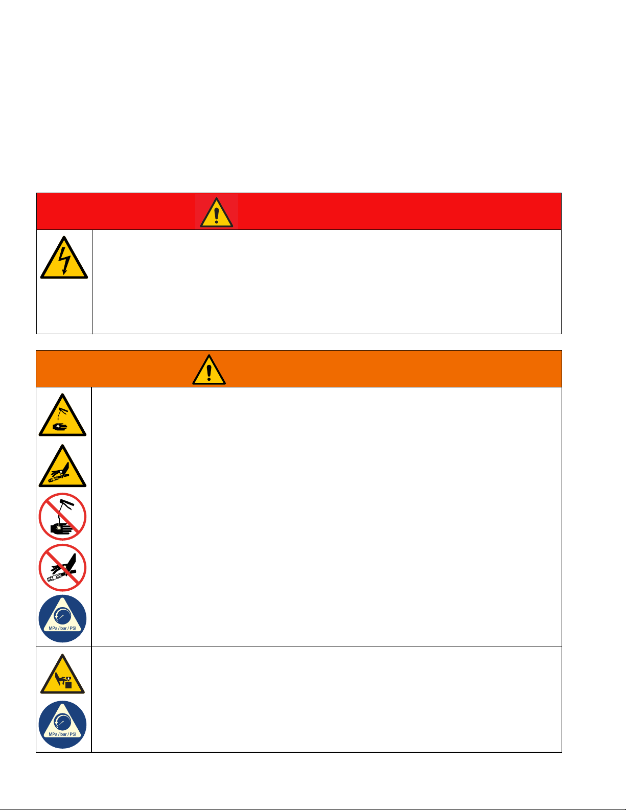
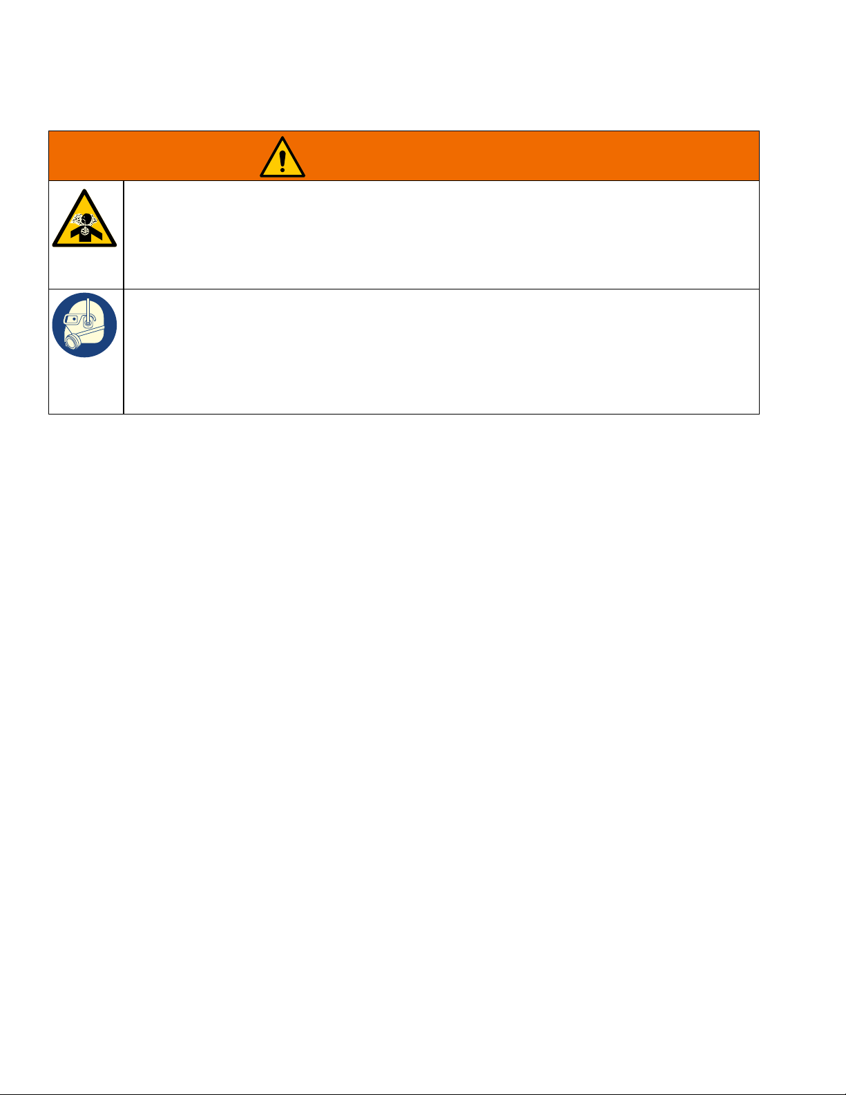
DANGER
SEVERE ELECTRIC SHOCK HAZARD
This equipment can be powered by more than 240 V. Contact with this voltage will cause death or
serious injury.
• Turn off and disconnect power at main switch before disconnecting any cables and before servicing
equipment.
• This equipment must be grounded. Connect only to grounded power source.
• All electrical wiring must be done by a qualified electrician and comply with all local codes and
regulations.
WARNING
SKIN INJECTION HAZARD
High-pressure fluid from dispensing device, hose leaks, or ruptured components will pierce skin. This
may look like just a cut, but it is a serious injury that can result in amputation. Get immediate surgical
treatment.
• Do not point dispensing device at anyone or at any part of the body.
• Do not put your hand over the fluid outlet.
• Do not stop or deflect leaks with your hand, body, glove, or rag.
• Follow the Pressure Relief Procedure when you stop dispensing and before cleaning, checking, or
servicing equipment.
• Tighten all fluid connections before operating the equipment.
• Check hoses and couplings daily. Replace worn or damaged parts immediately.
MOVING PARTS HAZARD
Moving parts can pinch, cut or amputate fingers and other body parts.
• Keep clear of moving parts.
• Do not operate equipment with protective guards or covers removed.
• Equipment can start without warning. Before checking, moving, or servicing equipment, follow the
Pressure Relief Procedure and disconnect all power sources.
8 3A6331G
Page 9
Warnings
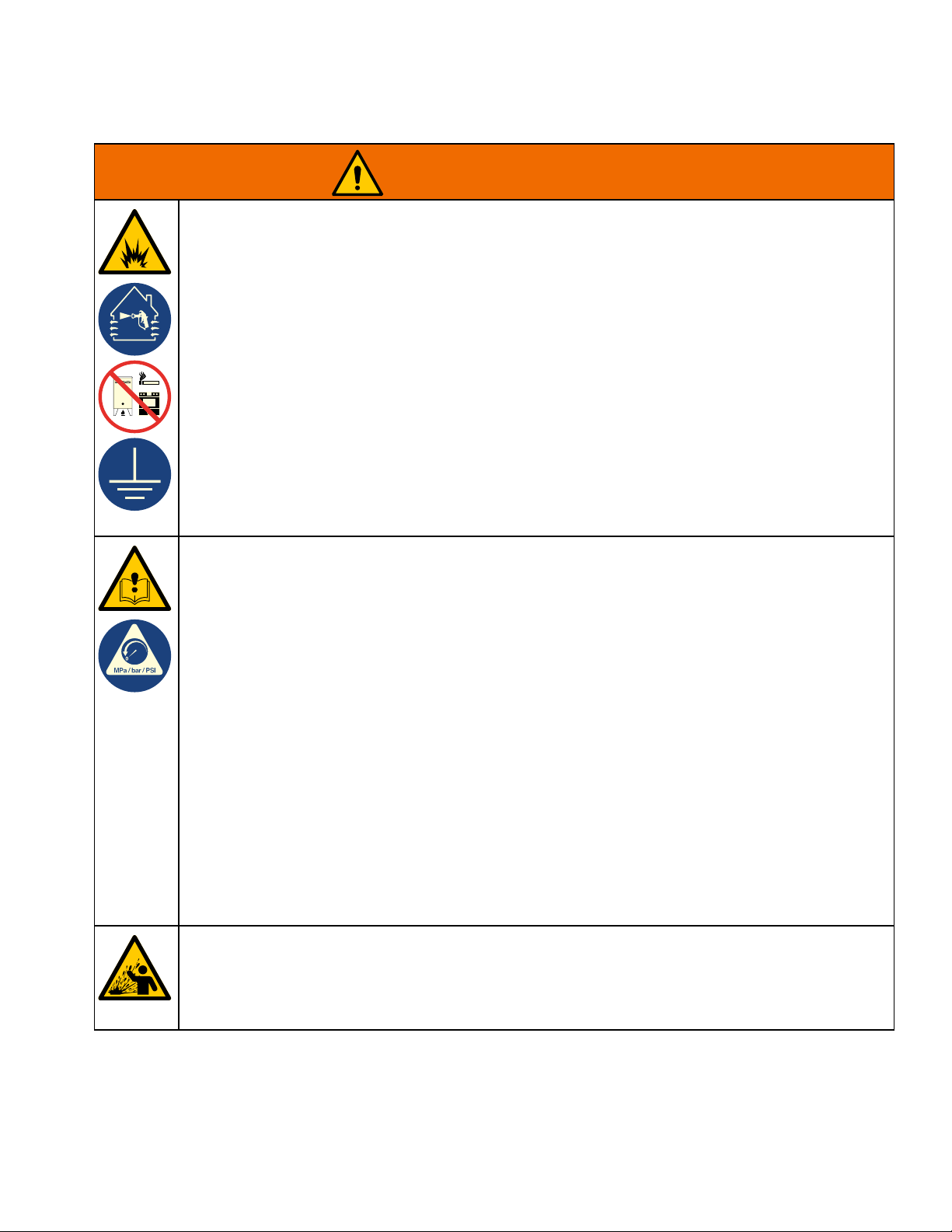
WARNING
FIRE AND EXPLOSION HAZARD
Flammable fumes, such as solvent and paint fumes, in work area can ignite or explode. Paint or
solvent flowing through the equipment can cause static sparking. To help prevent fire and explosion:
• Use equipment only in well-ventilated area.
• Eliminate all ignition sources; such as pilot lights, cigarettes, portable electric lamps, and plastic drop
cloths (potential static sparking).
• Ground all equipment in the work area. See Grounding instructions.
• Never spray or flush solvent at high pressure.
• Keep work area free of debris, including solvent, rags and gasoline.
• Do not plug or unplug power cords, or turn power or light switches on or off when flammable fumes
are present.
• Use only grounded hoses.
• Hold gun firmly to side of grounded pail when triggering into pail. Do not use pail liners unless they
are anti-static or conductive.
• Stop operation immediately if static sparking occurs or you feel a shock. Do not use equipment until
you identify and correct the problem.
• Keep a working fire extinguisher in the work area.
EQUIPMENT MISUSE HAZARD
Misuse can cause death or serious injury.
• Do not operate the unit when fatigued or under the influence of drugs or alcohol.
• Do not exceed the maximum working pressure or temperature rating of the lowest rated system
component. See Technical Specifications in all equipment manuals.
• Use fluids and solvents that are compatible with equipment wetted parts. See Technical
Specifications in all equipment manuals. Read fluid and solvent manufacturer’s warnings. For
complete information about your material, request Safety Data Sheets (SDSs) from distributor or
retailer.
• Turn off all equipment and follow the Pressure Relief Procedure when equipment is not in use.
• Check equipment daily. Repair or replace worn or damaged parts immediately with genuine
manufacturer’s replacement parts only.
• Do not alter or modify equipment. Alterations or modifications may void agency approvals and create
safety hazards.
• Make sure all equipment is rated and approved for the environment in which you are using it.
• Use equipment only for its intended purpose. Call your distributor for information.
• Route hoses and cables away from traffic areas, sharp edges, moving parts, and hot surfaces.
• Do not kink or over bend hoses or use hoses to pull equipment.
• Keep children and animals away from work area.
• Comply with all applicable safety regulations.
SPLATTER HAZARD
Hot or toxic fluid can cause serious injury if splashed in the eyes or on skin. During blow off of platen,
splatter may occur.
• Use minimum air pressure when removing platen from drum.
3A6331G 9
Page 10
Warnings
WARNING
TOXIC FLUID OR FUMES HAZARD
Toxic fluids or fumes can cause serious injury or death if splashed in the eyes or on skin, inhaled, or
swallowed.
• Read Safety Data Sheets (SDSs) to know the specific hazards of the fluids you are using.
• Store hazardous fluid in approved containers, and dispose of it according to applicable guidelines.
PERSONAL PROTECTIVE EQUIPMENT
Wear appropriate protective equipment when in the work area to help prevent serious injury, including
eye injury, hearing loss, inhalation of toxic fumes, and burns. Protective equipment includes but is not
limited to:
• Protective eyewear, and hearing protection.
• Respirators, protective clothing, and gloves as recommended by the fluid and solvent manufacturer.
10 3A6331G
Page 11
Component Identification
Component Identification
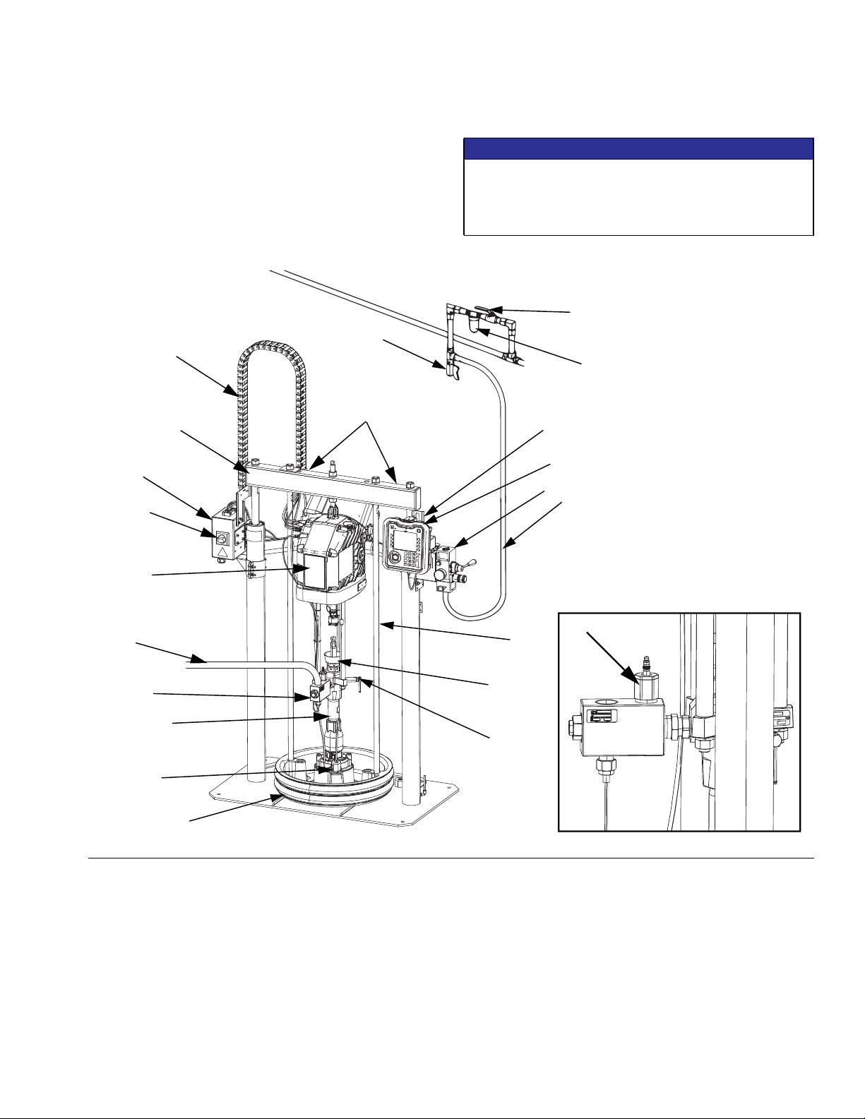
Typical Installation
D200 3 in. and D200s 6.5 in. Dual Post
EMC1223 Model
Shown
U
E
Lift Locations
A
K
M
B
NOTICE
Always lift the supply system at the proper lift locations
(see FIG. 1). Do not lift in any other way. Failure to lift
at the proper lift locations can result in damage to the
supply system.
W
V
X
F
G
T
NOTE: The Outlet Pressure Relief
Valve is used on Check-Mate 100cc
pumps only. See the E-Flo SP Electric
Pump Instructions-Parts manual for a
complete parts list.
S
Y
C
J
D
FIG. 1: Typical Installation
Key:
A Ram Assembly
B Electric Driver
C Displacement Pump
D Platen
E Cable Track
F Advanced Display Module (ADM)
G Integrated Air Controls (see F
J Platen Bleed Port
K Power Junction Box
M Disconnect Switch
IG. 2)
N
Z
R
P
N Platen Lift Rod
P Pump Bleed Valve
R Enclosed Wet Cup
S Fluid Line (not supplied)
T Air Line (not supplied)
U Air Line Drain Valve (not supplied)
V Air Filter (not supplied)
W Bleed Type Air Shutoff Valve (required) (not supplied)
X Level Sensors
Y Outlet Pressure Transducer
Z Outlet Pressure Relief Valve (Check-Mate 100 only)
3A6331G 11
Page 12
Component Identification
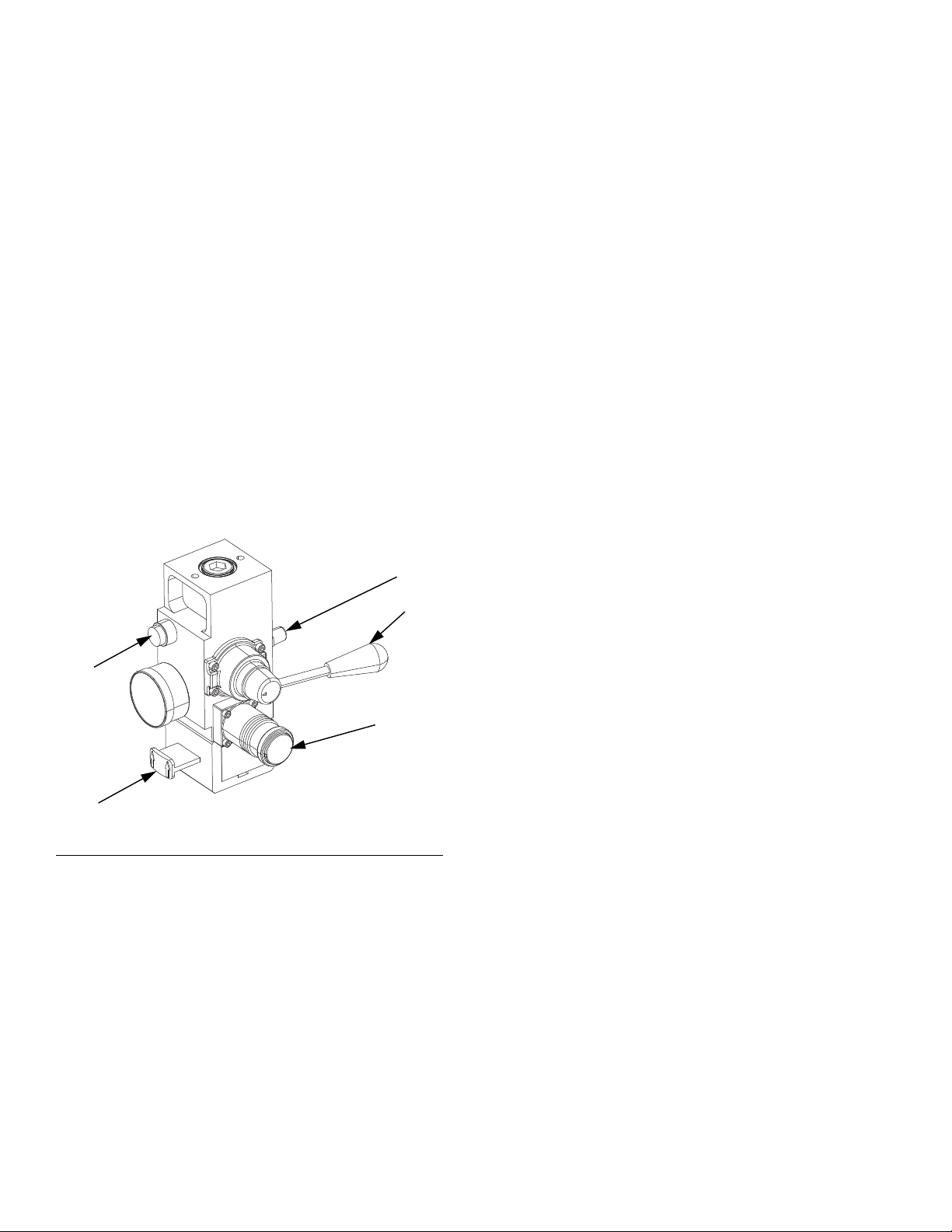
Integrated Air Control Module
D200, D200s, and D60 Models
The integrated air controls include:
• Main air slider valve (AA): turns air on and off to
the system. When closed, the valve relieves pressure downstream.
• Ram air regulator (AB): controls ram up and down
pressure and blowoff pressure.
• Ram director valve (AC): controls ram direction.
• Exhaust port with muffler (AD)
• Blowoff button (AE): turns air on and off to push
the platen out of an empty drum.
Integrated Air Line Accessories
See FIG. 1.
• Air line drain valve (U).
• Air line filter (V): removes harmful dirt and mois-
ture from compressed air supply.
• Second bleed-type air valve (W) (required): iso-
lates air line accessories for servicing. Locate
upstream from all other air line accessories.
• Air relief valve (required) (not visible):
automatically relieves excessive pressure.
AE
AA
FIG. 2. Integrated Air Control Module
AD
AC
AB
12 3A6331G
Page 13
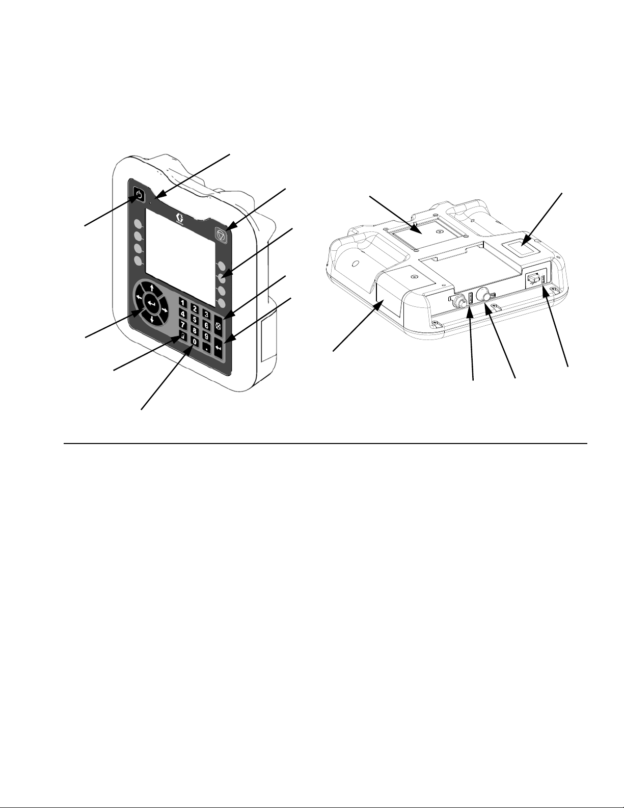
Advanced Display Module (ADM)
Front and Rear Views
BB
Component Identification
BA
BH
BG
BJ
FIG. 3: ADM Component Identification
Key:
BA Pump Enable
Enables the pump. Toggles between Active and
System Off.
BB Pump Status Indicator Light
BC Pump Soft Stop
Stops all pump processes and disables the pump.
BD Soft Keys
Defined by the icon on the screen next to the soft
key.
BE Cancel
Cancel a selection or number entry while in the
process of entering a number or making a selection.
Cancels the pump processes.
BF Enter
Accept change, acknowledge error, select item, and
toggle selected item.
BC
BE
BF
BD
BR
BP
BN
BG Lock/Setup
Toggle between run and setup screens.
BH Directional Keypad
Navigate within a screen or to a new screen.
BJ Numeric Keypad
BK Part Number Identification Label
BL USB Interface
BM CAN Cable Connection
Power and communication.
BN Module Status LEDs
Visual indicators to show the status of the ADM.
BP Token Access Cover
Access cover for software token.
BR Battery Access Cover
BK
BL
BM
3A6331G 13
Page 14
Component Identification
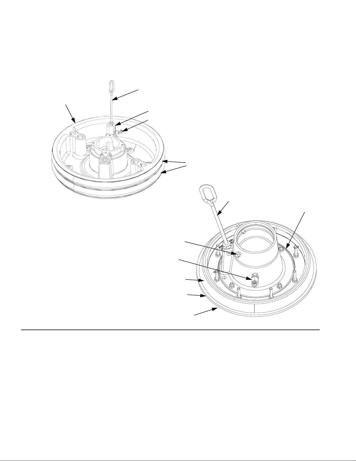
Platen Component Identification
Model 255319, 200 liter (55 gallon)
EF
EA
EG
EH
FIG. 4
EB
Model 256742 and 256745,
20 liter (5 gallon)
EF
EA
ED
EH
EC
EB
EJ
Key:
EA Plate
EB Wipers
EC Spacer
ED Cap Screws
EE Clamps (not shown)
EF Bleed Stick
EG Bleed Port
EH Air Assist Body Check Valve
EJ Wiper Plate (under wiper)
EK O-ring Seal (not shown)
14 3A6331G
Page 15
Junction Box Connections
Component Identification
C1
C2
C3
C4
FIG. 5
Key:
C1 CGA CAN Port
C2 GCA CAN Port
C3 Low and Empty Level Sensor Input
C4 Fluid Filter Solenoid Input
NOTE: See the E-Flo SP Software Instructions manual
for all I/O descriptions.
3A6331G 15
Page 16
Installation
Installation
All electrical wiring must be done by a qualified electrician and comply with all local codes and regulations.
Location
To properly locate and anchor the supply system, refer
to Dimensions on page 67.
NOTICE
Always lift the supply system at the proper lift locations
(see FIG. 1). Do not lift in any other way. Failure to lift
at the proper lift locations can result in damage to the
supply system.
Attach a lifting sling at the proper lift locations. Lift off the
pallet using a crane or a forklift.
NOTE: The lift ring on the driver is only to be used for
replacing the driver. Do not use it to lift the entire system.
Grounding
The equipment must be grounded to reduce the risk
of static sparking and electric shock. Electric or static
sparking can cause fumes to ignite or explode.
Improper grounding can cause electric shock.
Grounding provides an escape wire for the electric
current.
Electric pump: the pump is grounded through the
power cord.
Ram: the ram is grounded through the power cord.
Air and fluid hoses: use only electrically conductive
hoses with a maximum of 500 ft. (150 m) combined
hose length to ensure grounding continuity. Check the
electrical resistance of the hoses. If the total resistance
to ground exceeds 29 megaohms, replace the hose
immediately.
Air compressor: follow manufacturer’s recommendations.
Dispense valve: ground through connection to a prop-
erly grounded fluid hose and pump.
Position the ram so the driver, disconnect switch, air
controls, and ADM are easily accessible. Ensure that
there is enough space overhead for the ram to raise
fully.
Using the holes in the ram base as a guide, drill holes
for 1/2 in. (13 mm) anchors.
Ensure that the ram base is level in all directions. If necessary, level the base using metal shims. Secure the
base to the floor using 1/2 in. (13 mm) anchors that are
long enough to prevent the ram from tipping.
Fluid supply container: follow local code.
Solvent pails used when flushing: follow local code.
Use only conductive metal pails, placed on a grounded
surface. Do not place the pail on a non-conductive surface, such as paper or cardboard, which interrupts the
grounding continuity.
To maintain grounding continuity when flushing or
relieving pressure: hold a metal part of the dispense
valve firmly to the side of a grounded metal pail, then
trigger the valve.
16 3A6331G
Page 17
Installation
Power Requirements
The system requires a dedicated circuit protected with a
circuit breaker.
Voltage Phase Hz Current
200-240 VAC 1 50/60 20 A
400-480 VAC 1 50/60 10 A
Connect Power
NOTICE
To avoid equipment damage, route and secure a
power cord that is long enough to allow the full range
of movement for the ram.
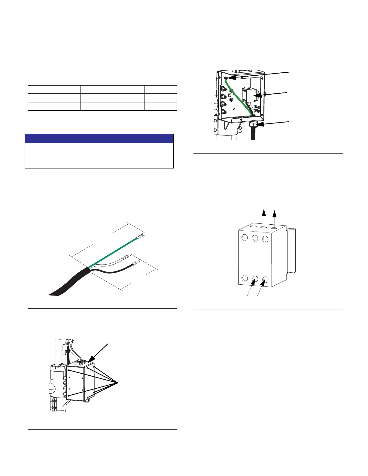
6. Cut power cord wires to the following lengths:
• Ground wire - 6.5 inches (16.5 cm)
• Power wires - 3.0 inches (7.6 cm)
• Add ferrules as necessary. See FIG. 6.
8. Insert the power cord through the cord grip and into
the junction box (K).
Ground Stud
Disconnect Switch
Terminal Block
Cord Grip
FIG. 8: Power Connection
9. Attach the ground wire to the ground stud inside the
junction box (K).
10. Refer to FIG. 9 and connect the wires from the power
cord into terminals 4T2 and 6T3 on the disconnect
switch terminal block.
LQ
LQ
FIG. 6: Power Cord
7. Remove the six screws holding the cover of the junction box (K), then remove the junction box cover.
K
Screws
1L1
3L2
5L2
2T1
4T2
6T3
FIG. 9: Disconnect Switch Terminal Block
11. Tighten the cord grip to securely hold the power cord
to the junction box (K).
12. Replace the junction box cover and secure it with the
six screws that were removed in step 2.
FIG. 7: Remove the Junction Box Cover
3A6331G 17
Page 18
Installation
Attach Drum Stops
The electric supply systems are shipped with drum
stops in place to help position the drum on the ram. For
replacement parts, order Kit 255477. The kit includes 2
each of capscrews, lock washers (not shown), and drum
stops.
Capscrews
Drum Stops
FIG. 10: Drum Stop Installation
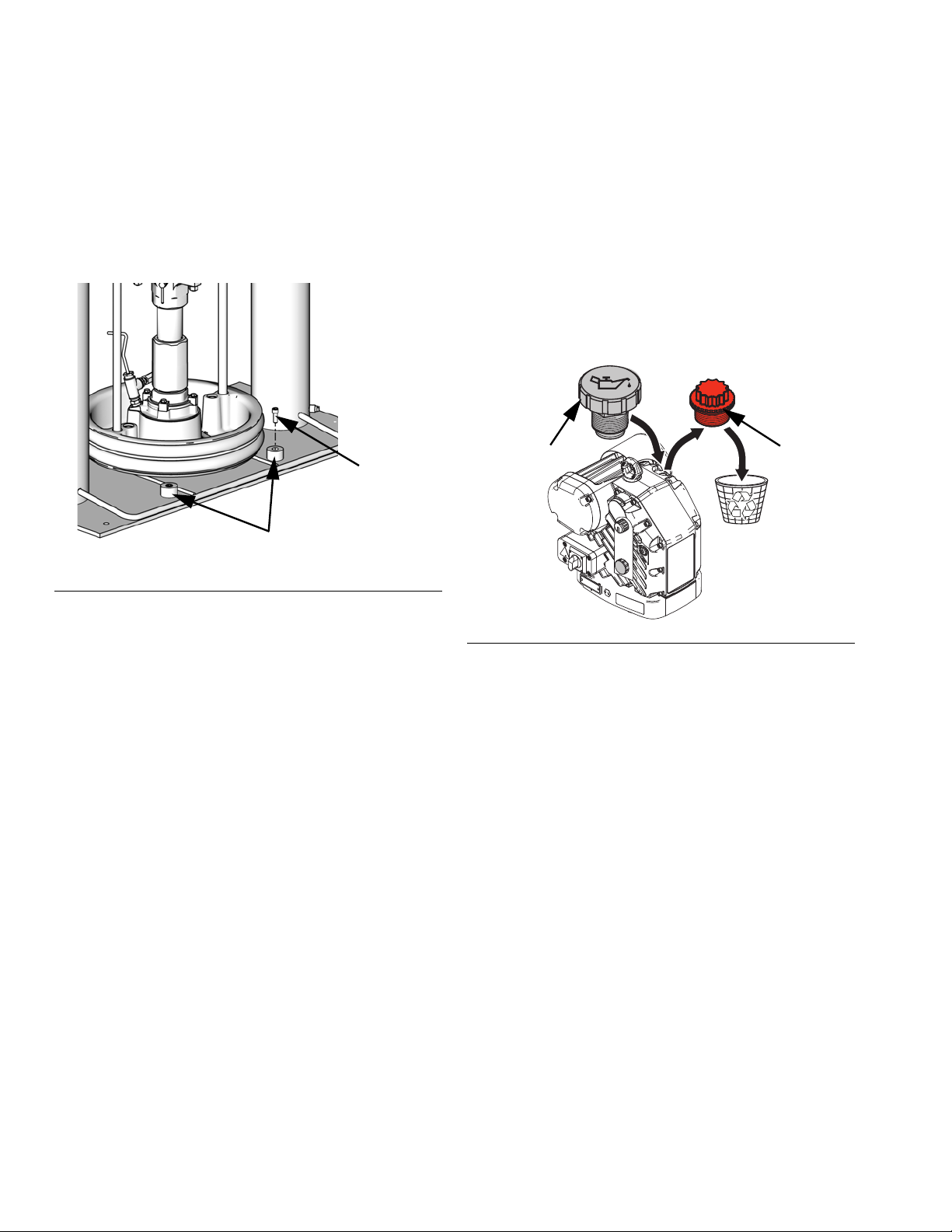
Install Vented Oil Cap Before Using Equipment.
The driver gear-box is shipped from the factory pre-filled
with oil. The temporary unvented cap prevents oil leaks
during shipment. This temporary cap must be replaced
with the vented oil cap supplied with the equipment,
before use.
NOTE: Prior to use, check oil level. Oil level should be
half way up the sight glass.
Vented Cap
Unvented
Cap
1. Locate the correct set of mounting holes on the ram
base.
2. Using the capscrews and lock washers, attach the
drum stops to the ram base.
Fluid Hose and Air Line Connections
Refer to FIG. 1 on page 11 for a typical installation.
Attach the fluid hose (not supplied) to the Outlet Check
Valve (E) connection.
Attach the air line (not supplied) to the bottom of the
Integrated Air Control (G) at the 3/4 in. NPT connection.
NOTE: Be sure all components are adequately sized
and pressure rated to meet the system’s requirements.
FIG. 11: Unvented and Vented Oil Caps
18 3A6331G
Page 19
Setup
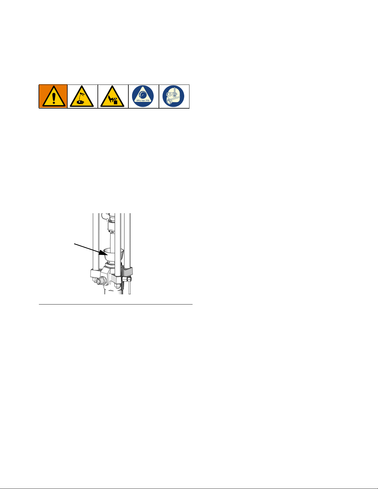
Wet Cup
Before starting, fill the wet cup (L) 1/3 full with Graco
Throat Seal Liquid (TSL) or a compatible solvent.
Torque the Wet Cup
The wet cup is torqued at the factory; however, throat
packing seals on Severe Duty pumps may relax over
time. Check wet cup torque frequently after initial
start-up and periodically after the first week of production. Maintaining proper wet cup torque is important to
extending seal life.
Setup
R
FIG. 12: Wet Cup
NOTE: MaxLife pumps use a special u-cup throat seal
that is non-adjustable and does not require periodic
torquing.
1. Follow the Pressure Relief Procedure on page 22.
2. Torque the wet cup (R) 95-115 ft-lbs (128-155 N•m)
using the packing nut wrench (supplied) whenever
necessary. Do not overtighten the wet cup. See the
table below for torque values.
3A6331G 19
Page 20
Startup
Startup
Letters in parenthesis are used in this section for reference to callouts in the Component Identification section starting on page 11.
Flush the Pump
To avoid fire and explosion, always ground the equipment and the waste container. To avoid static sparking and injury from splashing, always flush at the
lowest possible pressure.
NOTE: The pump is tested with lightweight oil, which is
left in to protect the pump parts. If the fluid you are using
may be contaminated by the oil, flush it out with a compatible solvent before using the pump.
Always flush at the lowest pressure possible. Check
connectors for leaks and tighten as necessary. Flush
with a fluid that is compatible with the fluid being dispensed and the equipment wetted parts.
3. Turn the disconnect switch (M) ON.
4. At the ADM (F), use the ADM’s arrow keys to select
the pump you want to flush from the Menu Bar.
NOTE: If multiple pumps are connected together, there
can be up to six pumps listed in the Menu Bar.
5. Enter the Edit screen for that pump by pressing the
soft key next to the icon.
6. Press the soft key next to the Pressure Mode
icon.
7. Enter 100 psi (0.69 MPa, 6.9 bar) as the pressure.
8. Press the soft key next to the Pump On/Off
icon to turn on the pump.
9. Adjust pressure as necessary.
10. Hold a metal part of the dispense valve firmly to the
side of a grounded metal pail.
11. Open the dispense valve and flush the system until
clear solvent flows from the gun/valve.
NOTE: Check with your fluid manufacturer or supplier
for recommended flushing fluids and flushing frequency.
NOTICE
To prevent damage to the pump from rust, never
leave water or water-based fluid in a carbon steel
pump overnight. If you are pumping a water-based
fluid, flush with water first. Then flush with a rust
inhibitor, such as mineral spirits. Relieve pressure,
but leave the rust inhibitor in the pump to protect
parts from corrosion.
NOTE: Refer to the E-Flo SP Software Instructions
manual for additional information about using the
software features of the ADM. See Related Manuals on
page 3.
1. Follow the Pressure Relief Procedure on page 22.
2. Place a pail of compatible solvent in the ram. See
Grounding instructions for solvent pails on page
16.
12. Exit the Edit screen by pressing the soft key next to
the icon.
13. Repeat steps 3 through 11 for each pump you want
to flush.
14. Follow the Pressure Relief Procedure on page 22.
15. Remove the solvent pail from the ram.
20 3A6331G
Page 21
Startup
Start and Adjust the Ram
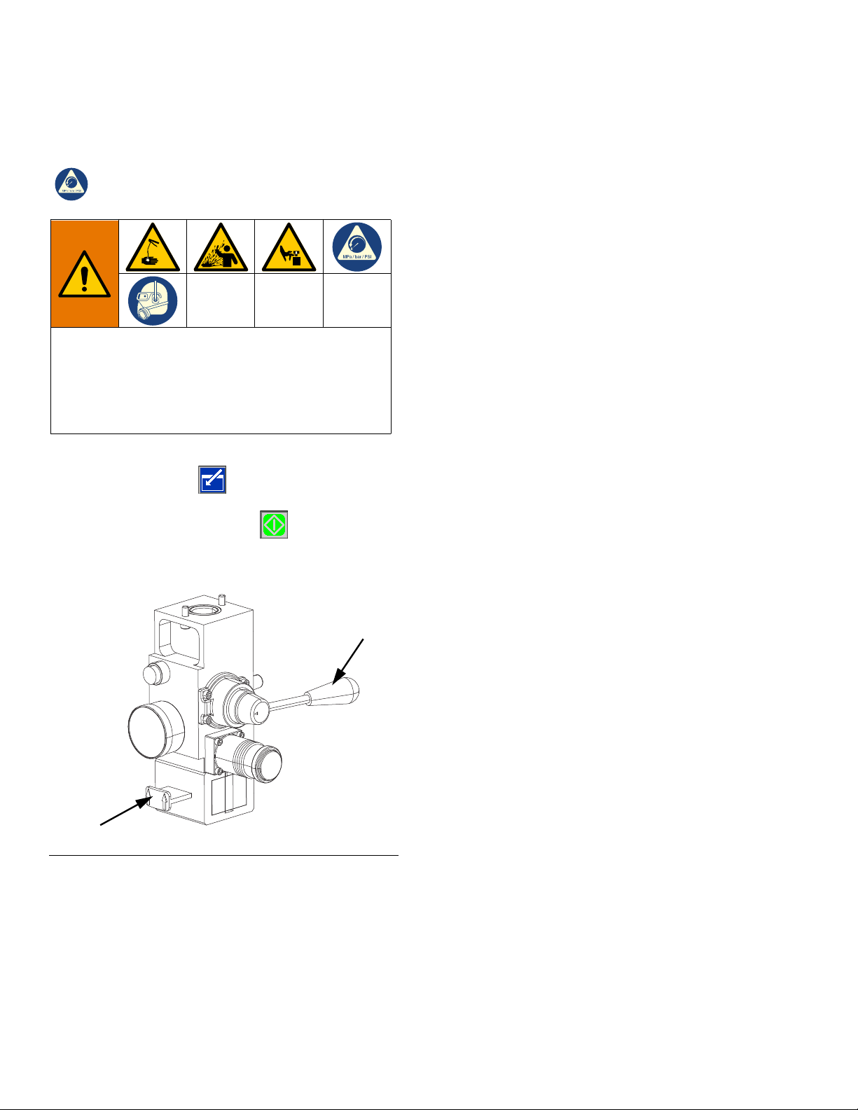
1. Turn the disconnect switch (M) OFF.
2. Raise the Ram by opening the main air slider valve
(AA) and setting the ram air regulator (AB) to 40 psi
(0.28 MPa, 2.8 bar).
3. Set the ram director valve handle (AC) to UP and let
the ram rise to its full height.
4. Set the ram director valve handle (AC) to neutral.
5. Lubricate the platen wiper (EB) with grease or other
lubricant compatible with the fluid you will pump.
6. Put a full drum/pail on the ram base and center it
under the platen (D).
7. Remove the drum/pail cover and smooth the surface of the fluid with a straightedge. To prevent air
from being trapped under the platen, scoop fluid
from the center of the pail to the sides, to make the
surface concave.
8. Adjust the drum/pail to be sure it is aligned with the
platen, and remove the platen bleed stick to open
the platen bleed port.
9. With hands away from the drum/pail and the platen,
push down on the ram director valve (AC) handle,
and lower the ram until the platen rests on the lip of
the drum/pail. Move the ram director valve handle to
the horizontal position (neutral).
10. Lower the ram:
a. Set the ram director valve (AC) to DOWN and
continue to lower the ram until fluid appears at
the platen bleed port.
b. Set the ram director valve to neutral, replace the
platen bleed stick, and tighten it securely.
Start and Adjust the Pump
1. With the disconnect switch (M) OFF, set the ram air
regulator (AB) to about 50 psi (0.35 MPa, 3.5 bar).
Set the ram director valve (AC) to DOWN.
2. Turn the driver disconnect switch (M) ON.
3. Start the pump. See the E-Flo SP Software Instructions manual for instructions on operating the system.
D60
Platen Bleed Stick
EB
4. Keep the ram director valve (AC) set to DOWN
while the pump is operating.
NOTE: Increase air pressure to the ram if the pump
does not prime properly with more viscous fluids.
Decrease air pressure if fluid is forced out around the
top seal or platen.
D200
Platen Bleed Stick
EB
3A6331G 21
Page 22
Pressure Relief Procedure
Pressure Relief Procedure
Follow the Pressure Relief Procedure whenever
you see this symbol.
This equipment stays pressurized until pressure is
manually relieved. To help prevent serious injury from
pressurized fluid, such as skin injection, splashing
fluid and moving parts, follow the Pressure Relief Procedure when you stop spraying and before cleaning,
checking, or servicing the equipment.
1. At the ADM, enter manual mode by pressing the
soft key next to the icon.
2. Press the soft key next to the icon to stop the
pump.
7. Hold a metal part of the dispense valve firmly to the
side of a grounded metal pail, and open the dispense valve to relieve pressure.
8. Open your system’s fluid line drain valve and open
the pump bleed valve (P). Have a container ready to
catch the drainage.
9. Leave the pump bleed valve (P) open until ready to
dispense again.
3. Turn the disconnect switch (M) OFF.
AC
AA
FIG. 13: Air Control for Pressure Relief
4. Close the main air slider valve (AA).
5. Set the ram director valve (AC) to DOWN. The ram
will slowly drop.
6. Once the ram is completely down, jog the ram director valve up and down to bleed air from the ram cylinders.
22 3A6331G
Page 23
Shutdown and Care of the Pump
Change Drums
NOTICE
To prevent damage to the pump from rust, never
leave water or water-based fluid in a carbon steel
pump overnight. If you are pumping a water-based
fluid, flush with water first. Then flush with a rust
inhibitor, such as mineral spirits. Relieve pressure,
but leave the rust inhibitor in the pump to protect
parts from corrosion.
1. Set the ram director valve (AC) to DOWN, and lower
the ram to the desired position for shutdown.
2. Set the ram director valve (AC) to neutral.
1. Stop the pump.
2. Set the ram director valve (AC) to UP to raise the
platen, and immediately press and hold the blowoff
air button (AE) until the platen is completely out of
the drum. Use the minimum amount of air pressure
necessary to push the platen out of the drum.
Shutdown and Care of the Pump
3. Stop the pump at the bottom of the stroke to prevent
fluid from drying on the exposed displacement rod
and damaging the throat packings. See the E-Flo
SP Software Instructions manual for information
about jogging the pump. See Related Manuals on
page 3.
4. Always flush the pump before the fluid dries on the
displacement rod. Follow steps to Flush the Pump
on page 20.
Excessive air pressure in the material drum could
cause the drum to rupture, causing serious injury. The
platen must be free to move out of the drum. Never
use drum blowoff air with a damaged drum.
3. Release the blowoff air button (AE) and allow the
ram to rise to its full height.
4. Remove the empty drum.
5. Inspect the platen and, if necessary, remove any
remaining material or material build–up.
3A6331G 23
Page 24
Maintenance
Maintenance
Driver Maintenance
NOTICE
Do not open/remove the gear cover. The gear side is
not intended to be serviced. Opening the gear cover
may alter the factory set bearing pre-load and may
reduce the product life.
Preventative Maintenance Schedule
The operating conditions of your particular system
determine how often maintenance is required. Establish
a preventative maintenance schedule by recording
when and what kind of maintenance is needed, and
then determine a regular schedule for checking your
system.
Change the Oil
NOTE: Change the oil after a break-in period of 200,000
to 300,000 cycles. After the break-in period, change the
oil once per year.
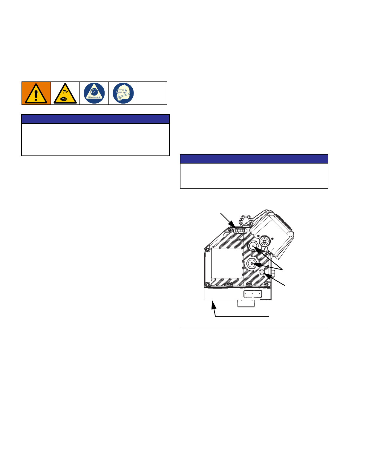
Check Oil Level
Refer to FIG. 14 below. Check the oil level in the sight
glass on a regular basis. The oil level should be near the
halfway point of the sight glass when the driver is not
running. If the oil is low, open the fill cap and add Graco
Part No. 16W645 ISO 220 silicone-free synthetic EP
gear oil.
The oil capacity is approximately 1.0 - 1.2 quarts (0.9 -
1.1 liters). Do not overfill.
NOTICE
Only use oil with Graco part number 16W645. Any
other oil may not lubricate properly and can cause
damage to the drive train.
Fill Cap
1. Follow the Pressure Relief Procedure on page 22.
2. Place a minimum 2 quart (1.9 liter) container under
the oil drain port.
3. Remove the oil drain plug. See FIG. 14 for the loca-
tion of the drain plug. Allow all oil to drain from the
driver.
4. Reinstall the oil drain plug. Torque to 18-23 ft-lb
(25-30 N•m).
5. Open the fill cap and add Graco Part 16W645 ISO
220 silicone-free synthetic EP gear oil. Check the oil
level in the sight glass. Fill until the oil level is near
the halfway point of the sight glass. The oil capacity
is approximately 1.0 - 1.2 quarts (0.9 - 1.1 liters). Do
not overfill.
6. Reinstall the fill cap.
Bearing Pre-loads
Sight Glass
Oil Drain Plug
FIG. 14: Sight Glass and Oil Fill Cap
Bearing Pre-Load
The bearing pre-loads are factory set and are not user
adjustable. Do not adjust the bearing pre-loads. See
APD20 Advanced Precision Driver Instructions-Parts
manual for maintenance information.
24 3A6331G
Page 25

Maintenance
Platen Maintenance
See FIG. 15. If the platen does not come out of the pail
easily when the pump is being raised, the air assist tube
(F) or check valve may be plugged. A plugged valve
prevents air from reaching the underside of the plate to
assist in raising it from the pail.
1. Follow the Pressure Relief Procedure on page 22.
2. Refer to parts illustration on page 50 and
disassemble air assist valve as shown.
3. Clear air assist tube (AT) in platen. Clean all parts of
valve and reassemble.
4. Remove bleed stick (EF) from platen. Push bleed
stick through bleed relieve ports to remove material
residue.
Adjust Spacers
Tapered and Straight Sided Pails
The platen is supplied for use with 20 liter (5 gallon), 30
liter (8 gallon), and 60 liter (16 gallon) straight sided
pails, but only single wiper platens can be easily
modified for use with tapered pails.
Platen with Tapered Pails
1. Follow the Pressure Relief Procedure on page 22.
2. Working from the bottom, use screwdriver to pry
spacer (EC) loose. Work spacer upward completely
above the flange of the platen. See FIG. 16.
3. By hand, angle spacer (EC) and work it off the plate,
pulling it down over the flange and bottom wipers
(EB). See FIG. 17.
4. Save spacer (EC), as it is required for other applications.
EF
FIG. 15
1
To use Model 255745 platens
with tapered pails, the spacer
(EC) must be removed.
AT
r_255468_313527_33a
EC
FIG. 16
EB
EC
r_255468_313527_30a
3A6331G 25
Page 26

Maintenance
Platen with straight sided pail
1. Follow the Pressure Relief Procedure on page 22.
2. Ensure large diameter of spacer (EC) is facing
down. Work spacer (EC) up over the platen by
hand completely above the flange of the platen. See
FIG. 17.
3. Working from the top, use screwdriver to position
spacer (EC) between flange and wipers (EB). See
FIG. 18.
EC
EB
r_255468_313527_30a
FIG. 17: Sliding spacer
Remove and Reinstall Wipers
Disassemble 20, 30, and 60 Liter Wiper Assemblies
1. Follow the Pressure Relief Procedure on page 22.
2. Remove wiper assembly; see FIG. 35 on page 50:
a. For all single wiper platens: Remove two clips
(470) with needle nose pliers and remove platen
cover (469).
b. Remove eight nuts (459) that hold wiper assem-
bly to platen casting (451) and remove wiper
assembly.
c. See Reassemble 20, 30, and 60 Liter Wiper
Assemblies to change wiper sizes, styles, or a
complete wiper assembly.
3. Remove eight nuts (459) on wiper assembly.
4. Separate top plate (457), spacer (452), wiper(s)
(453), wiper support (454), and bottom plate (455).
5. Clean, inspect, and replace worn components.
Reassemble 20, 30, and 60 Liter Wiper Assemblies
EC
EB
FIG. 18: Installing Spacer
r_255468_313527_32a
1. Assemble wiper assembly; see FIG. 35 on page 50:
a. For single wiper assemblies with carbon steel
platens: Place bottom plate (455) on flat surface. Place wiper support (454), wiper (453),
spacer (452), and top plate (457) on bottom
plate (455).
b. For single wiper assemblies with SST platens:
Place bottom plate (455) on flat surface. Place
wiper support (454), wiper (453), flowered wiper
support (460), PTFE spacer (452), and top plate
(457) on bottom plate (455).
c. For double wiper assemblies: Place bottom
plate (455) on flat surface. Place wiper support
(454), wiper (453), spacer (452), wiper (453)
and top plate (457) on bottom plate (455).
2. Install eight nuts (459) on outer ring. Torque to 45
in-lbs (61 N•m).
3. Replace o-ring (456), or install new o-ring under
platen casting (451). Use lubricant to hold in place.
26 3A6331G
Page 27

4. Install platen casting (451). Tighten with four nuts
(459).
Remove 55 Gallon Platen Wipers
Maintenance
1. Follow the Pressure Relief Procedure on page 22.
2. Turn the disconnect switch (M) to OFF.
3. To replace worn or damaged wipers (EB), raise
platen up out of drum. Remove drum from base.
Wipe fluid off of platen.
4. Cut top and bottom wipers with knife and remove
from platen. See FIG. 19.
EB
TI10613A
FIG. 19
Reinstall 55 Gallon Platen Wipers
1. Using a wooden or plastic tool to prevent damage to
the wiper (EB), clean all material from seal grooves.
EB
TI10614A
FIG. 20
Remove 55 Gallon Platen Hose Wipers
1. Follow the Pressure Relief Procedure on page 22.
2. Turn the disconnect switch (M) to OFF.
3. To replace worn or damaged wipers (EB), raise
platen up out of drum. Remove drum from base.
Wipe fluid off of platen.
4. Loosen ends of banding (410) with jack screw. See
FIG. 21.
2. Working from the bottom, angle one wiper (EB) over
back of platen. See FIG. 20.
3. Insert wiper (EB) in top groove and run front of wiper
into groove.
4. Insert second wiper (EB) in lower groove and run
front of wiper into groove.
5. Lubricate outside of wiper with lubricant compatible
with material being pumped. Check with material
supplier.
410
WLD
FIG. 21
3A6331G 27
Page 28

Maintenance
Reinstall 55 Gallon Plate Hose Wipers
1. Clean all material from the seal grooves. Lubricate
ram plate grooves before assembly.
2. Assemble two bands (410) together. Align one end
of band about 9 in. from jack screw and tape
attached band. Install screw jack in slot.
410
3. Insert jack screw end of band (410) into hose (408
or 409) and push completely through hose.
WLD
410
408, 409
NOTE: To prevent material from potentially leaking past
both hoses, ensure hose (408,409) seams are 90°-180°
apart, and not on top of each other.
408
409
410 (x2)
WLD
WLD
4. Lubricate outside of hoses (408,409) and place on
upper or lower groove on plate. Adjust hose and
band so that the angled ends of hose press against
each other. Tighten two ends of banding (410)
together with jack screw.
410
WLD
5. Work hose to completely close gap at the ends.
28 3A6331G
Page 29

Troubleshooting
Troubleshooting
2. Check all possible problems and causes before
disassembling the ram, pump, or platen.
NOTE: Refer to Supply Unit Operation manual for
descriptions of DataTrak diagnostic codes.
NOTE: Refer to your pump package manual for pump
1. Follow Pressure Relief Procedure, page 22,
before checking or repairing the ram, pump, or
platen.
Problem Cause Solution
Ram will not raise or lower. Closed air valve or clogged air line. Open, clear.
Not enough air pressure. Increase.
Worn or damaged piston. Replace. See Supply Unit Repair on
Hand valve closed or clogged. Open, clear.
Ram raises and lowers too fast. Air pressure is too high. Decrease.
Air leaks around cylinder rod. Worn rod seal. Replace. See Supply Unit Repair on
Fluid squeezes past ram plate wipers.
Pump will not prime properly or
pumps air.
Air assist valve will not hold drum
down or push plate up.
Air pressure too high. Decrease.
Worn or damaged wipers. Replace. See Remove and Rein-
Not enough pressure. Increase pressure setting.
Worn or damaged piston. Replace. See pump manual.
Hand valve closed or clogged. Open, clear. See Platen Mainte-
Hand valve is dirty, worn, or damaged.
Closed air valve or clogged air line. Open, clear. See Platen Mainte-
Not enough air pressure. Increase.
Valve passage clogged. Clean. See Platen Maintenance on
troubleshooting.
page 34.
page 34.
stall Wipers on page 26.
nance on page 25.
Clean, service.
nance on page 25.
page 25.
3A6331G 29
Page 30

Repair
Repair
Disconnect Pump from Platen
4. Carefully pull pump away to prevent damage to
pump inlet and remove o-ring (428).
20, 30, and 60 Liter Platen
1. Follow the Pressure Relief Procedure on page 22.
The pump is mounted to the platens by different mounting kits. See the Repair Kits on page 55.
55 Gallon Platen
1. Follow the Pressure Relief Procedure on page 22.
2. Turn the disconnect switch (M) to OFF.
3. Remove four hex screws (426), four clamps (427),
and washers (425).
428
426
425
427
428
2. Turn the disconnect switch (M) to OFF.
3. Loosen two 5/16 in. screws (462) from platen.
4. Carefully pull pump away to prevent damage to
pump inlet. If using a pump with intake adapter,
remove screws (472), adapter (471), and o-rings
(463) from pump inlet.
428
426
425
427
426
425
427
TI10422A
Check-Mate Mounting
FIG. 22: 55 Gallon Mounting Kit
463
462
r_255648_313527_35a
Check-Mate Mounting
FIG. 23: 20, 30, and 60 liter mounting kit
30 3A6331G
Dura-Flo SS Mounting
471
462
Dura-Flo SS Mounting
472
463
Dura-Flo CS Mounting
471
462
Dura-Flo CS Mounting
472
463
Page 31

Repair
Connect Platen
55 Gallon Platen
1. Place o-ring (428) from mounting kit on the platen. If
attached to plate, place displacement pump onto
platen. See FIG. 22.
2. Secure pump’s intake flange to plate with screws
(426), washers (425), and clamps (427) included in
mounting kit 255392.
20, 30, and 60 Liter Platen
NOTE: Before installing the 20, 30, or 60 liter platen to a
pump with an intake adapter, install adapter and o-ring
from mounting kit using the two set screws. See FIG. 23.
1. Place o-ring (463) from mounting kit on pump
intake. Loosen the pump intake flange screws (462)
and carefully lower pump onto o-ring (463) and
platen.
2. Secure pump’s intake flange to plate with screws
(462).
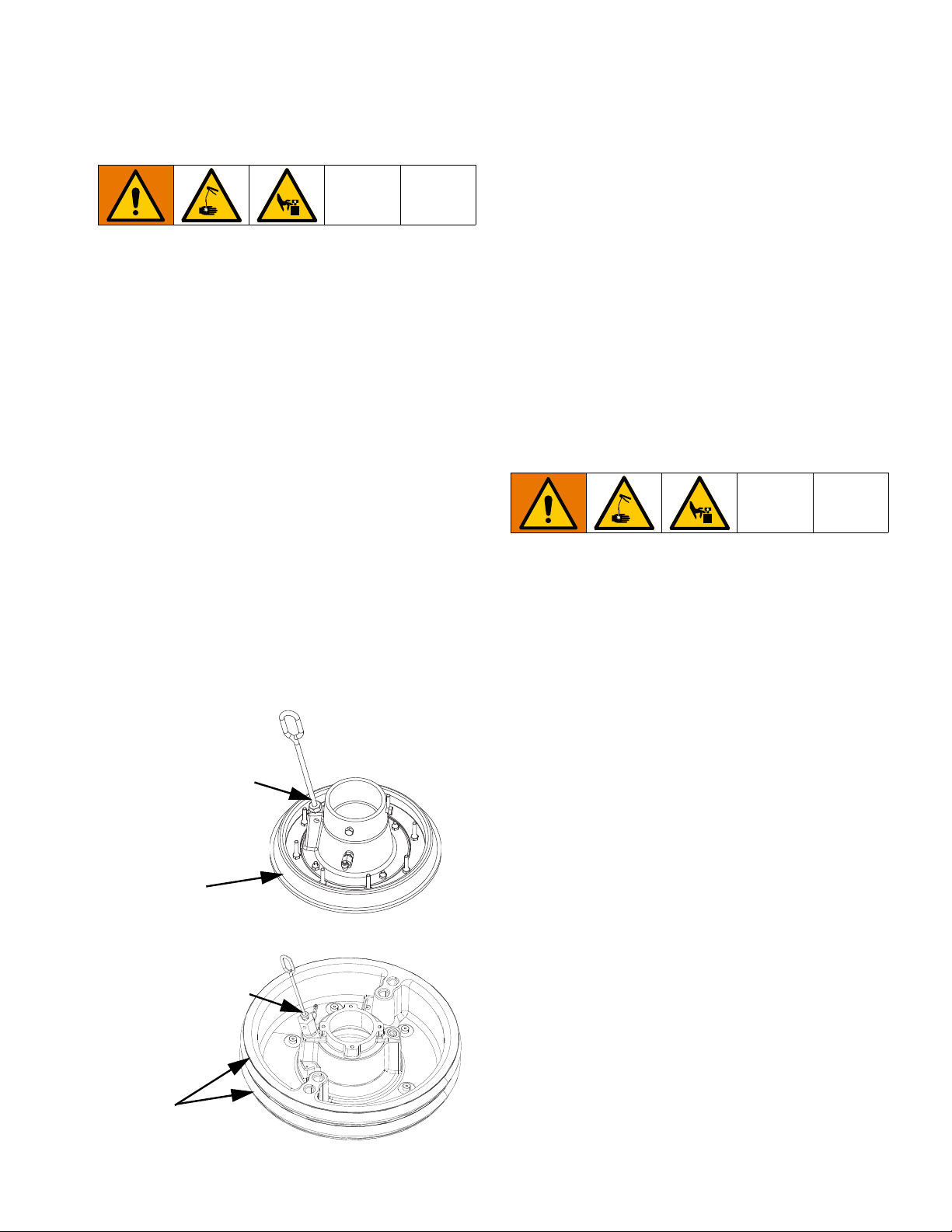
Remove Displacement Pump
The procedure for removing your displacement pump
depends on which driver and platen your unit uses. Find
your ram unit, driver, and platen below to remove the
displacement pump. Refer to your displacement pump
manual to repair the displacement pump.
If the driver does not require servicing, leave it attached
to its mounting. If the driver does need to be removed,
see Remove Driver on page 33.
D200 3 in. and D200s 6.5 in. Supply Units
1. Follow the Pressure Relief Procedure on page 22.
2. Turn the disconnect switch (M) to OFF.
3. See Disconnect Displacement Pump in your
pump package manual.
4. Open the main air slider valve (AA).
Remove Wipers
See Remove and Reinstall Wipers on page 26.
Install Wipers
See Remove and Reinstall Wipers on page 26.
5. Raise the driver:
a. Loosen nut (105a) under ram bar and thread it
down the threaded rod (106) to the lift ring
adapter (107) holding the driver. Use wrench on
nut (105) on top of ram bar to raise driver.
106
105
105a
107
FIG. 24
3A6331G 31
Page 32

Repair
b. For driver with smaller platens and all supply
units: See procedure for D60 3 in. Dual Post
Supply Units on page 32.
6. See Disconnect Pump from Platen on page 30 to
disconnect the platen from the displacement pump.
7. Use two people to lift out the displacement pump.
Install Displacement Pump
D200 3 in. and D200s 6.5 in. Supply Units
1. Insert displacement pump on platen. Follow Connect Platen steps on page 31.
2. See Reconnect Displacement Pump in your pump
package manual.
3. Connect driver:
a. Use wrench on nut (105) on top of ram bar to
lower driver onto displacement pump. See FIG.
24 on page 31. Thread nut (105) up and tighten
it under ram bar. Tighten nut (105) below the
crossbar to 25 ft-lb (34 N•m) maximum.
D60 3 in. Dual Post Supply Units
1. Raise ram to install displacement pump to platen.
2. Insert displacement pump on platen. Follow Con-
nect Platen steps on page 31.
FIG. 25
D60 3 in. Dual Post Supply Units
1. Follow the Pressure Relief Procedure on page 22.
2. Turn the disconnect switch (M) to OFF.
3. See Disconnect Displacement Pump in your
pump packages manual.
4. See Disconnect Pump from Platen on page 30 to
disconnect the platen from the displacement pump.
5. Open the main air slider valve (AA).
6. Raise the ram assembly to lift the driver away from
the displacement pump.
3. See Reconnect Displacement Pump in your pump
packages manual.
7. Remove displacement pump and service as
needed.
32 3A6331G
Page 33

Remove Driver
To avoid serious injury when installing and removing
the driver, make sure the driver is supported at all
times.
Repair
1. Follow the Pressure Relief Procedure on page 22.
2. Turn the disconnect switch (M) OFF.
3. See Disconnect Displacement Pump in your
pump package manual.
4. Disconnect power from the driver:
a. Remove the driver housing cover (HC).
b. Disconnect the wires inside the driver housing.
c. Loosen the cord grip (CG).
d. Remove wires from driver housing by pulling
them through the cord grip (CG).
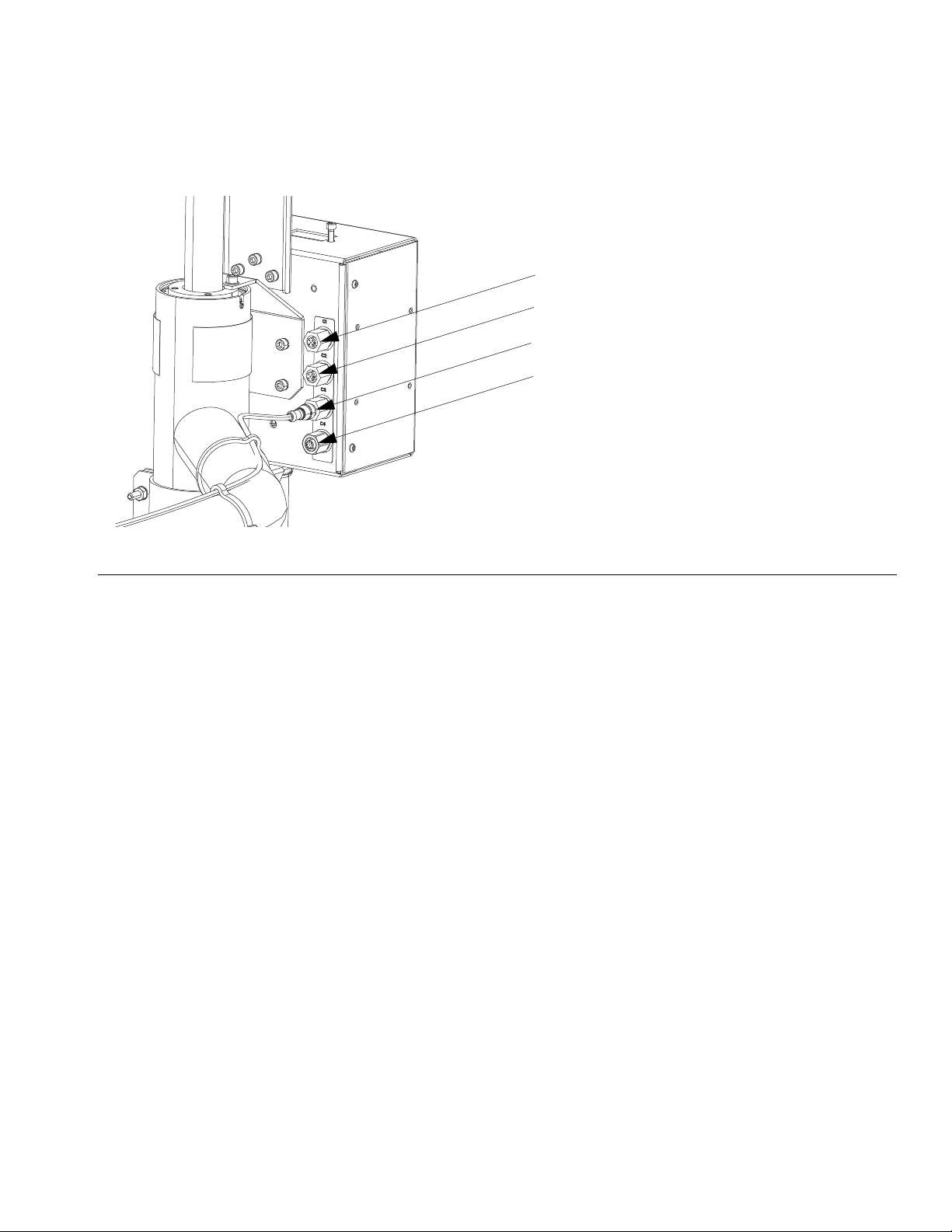
e. Disconnect the cables connected to ports 1-6
on the side of the driver, shown in FIG. 27.
HC
FIG. 27
5. Disconnect driver:
a. D200 3 in. and D200s 6.5 in. supply units:
Loosen nut (125) below crossbar. Use wrench
to hold lift ring adapter (127) in place and loosen
threaded rod (126) above crossbar with another
wrench. See FIG. 28.
126
125
125
127
FIG. 28: 55 Gallon Platen
b. D60 3 in. supply units: Remove screws (255)
CG
FIG. 26
FIG. 29: D60 with Ram
3A6331G 33
and washers (256) from mounting plate (259).
Using a secure hoist, lift the driver from the
mounting plate (259). See FIG. 29.
259
256
255
Page 34

Repair
Install Driver
To avoid serious injury when installing and removing
the driver, make sure the driver is supported at all
times.
D200 3 in. and D200s 6.5 in. Supply Units
55 gallon platen:
1. Using a capable hoist, insert tie rods into displacement pump and secure driver to pump.
a. See Reconnect Displacement Pump in your
pump package manual.
b. Install threaded rod (126) through center hole in
the crossbar. Install lock washers (124) and
nuts (125) onto threaded rod (126), both above
and below crossbar. Use wrench to hold lift ring
adapter (127) and tighten threaded rod (106)
into lift ring adapter (127) using another wrench.
See FIG. 30.
c. Tighten nut (125) below crossbar to 25 ft-lb (34
N•m) maximum.
2. Connect power to the driver. Follow a-e of step 4 on
page 33 in reverse.
3. Turn the disconnect switch (M) ON.
D60 3 in. Dual Post Supply Unit
1. Using a secure hoist, attach driver to mounting plate
(259) with screws (255) and washers (256). See
FIG. 29 on page 33.
2. See Reconnect Displacement Pump in your pump
package manual.
3. Connect power to the driver. Follow a-e of step 4 on
page 33 in reverse.
Supply Unit Repair
To reduce the risk of serious injury whenever you are
instructed to relieve pressure always follow the
Pressure Relief Procedure on page 22. Do not use
pressurized air to remove the guide sleeve or the
piston.
D200s 6.5 in. Ram Piston Rods
d. Tighten nut (125) above crossbar to lock driver
in place.
126
125
124
125
FIG. 30
Always service both cylinders at the same time. When
you service the lift rod always install new o-rings in the
piston rod seal and ram piston.
Disassemble Piston Rod Seal
1. Follow the Pressure Relief Procedure on page 22.
2. Turn the disconnect switch (M) OFF.
3. Remove the nuts (123) and lockwashers (122) holding the tie bar (219) to the piston rods (132). See
parts illustration on page 38.
4. Remove nuts (303, 305) and washers (302, 304).
See parts illustration on page 44.
127
5. Lift tie bar (219) off of rods.
6. Remove retaining ring (136) by gripping the ring tab
with a pair of pliers and rotating the ring out of its
groove.
7. Remove snap ring (134) and rod wiper (133).
8. Remove guide sleeve (135) by sliding it off of rod
(132). Four 1/4 in -20 holes are provided to ease
removal of the guide sleeve.
34 3A6331G
Page 35

Repair
9. Inspect parts for wear or damage.
134
136
137
133
142
135
132
TI10784A
FIG. 31: 6.5 in. Piston Rod Seal
Assemble Piston Rod Seal
1. Install new o-rings (137,142), rod wiper (133), and
snap ring (134). Lubricate packings with o-ring lubricant.
2. Slide guide sleeve (135) onto rod (132) and push it
into cylinder. Replace retaining ring (136) by feeding
it around the guide sleeve groove.
7. Remove guide sleeve (135) and slide it off piston
rod (132).
NOTICE
Do not tilt the piston rod to one side when removing it
from the base or when installing it. Such movement
can damage the piston or inside surface of the base
cylinder.
8. Carefully lay piston (141) and rod (132) down so rod
will not be bent. Remove bottom retaining ring (138)
and o-ring (139). Remove piston guide band (140).
Slide piston (141) off piston rod (132).
132
139
138
137
141
140
3. Reinstall tie bar (219) using nuts (123) and lockwashers (122). Torque to 40 ft-lb (54 N•m).
4. Reinstall washers (302, 304) and nuts (303, 305).
Disassemble Ram Piston
1. Follow the Pressure Relief Procedure on page 22.
2. Turn the disconnect switch (M) OFF.
3. Remove nuts (123) and lockwashers (122) holding
the tie bar (219) to the piston rods (132). See page
38.
4. Remove nuts (303, 305) and washers (302, 304).
See parts illustration on page 44.
5. Lift tie bar (219) off rods.
6. Remove retaining ring (136) by gripping the ring tab
with a pair of pliers and rotating the ring out of its
groove.
TI10785A
FIG. 32: 6.5 in. Ram Piston
Assemble Ram Piston
1. Install new o-rings (139, 137) on piston rod (132)
and piston (141). Lubricate the piston (141) and
o-rings (139, 137). Reinstall piston (141) and lower
retaining ring (138) onto piston rod (132). Install piston guide band (140) onto piston (141).
2. Carefully insert piston (141) into cylinder and push
rod (132) straight down into cylinder. Add three
ounces of lubricant to each cylinder after inserting
the piston (141).
3. Slide guide sleeve (135) onto piston rod (132).
4. Install retaining ring (134) and tie bar (219). Perform
steps to Disassemble Ram Piston in reverse
order.
3A6331G 35
Page 36

Repair
D200 and D60 3 in. Ram Piston Rods
Always service both cylinders at the same time. When
you service the piston rod always install new o-rings in
the piston rod seal and ram piston.
Disassemble Piston Rod Seal and Bearing
1. Follow the Pressure Relief Procedure on page 22.
2. Access piston rod seal and bearing.
a. For D200 3 in. Ram: Remove nuts (125) and
lockwashers (124) holding the tie bar (219) to
the piston rods (246). Remove nuts (305) and
washers (304). Remove tie bar (219). Refer to
parts illustration on page 40.
b. For D60 3 in. Ram: Ensure ram is in lowest
position. Remove nuts (125) and lockwashers
(254) from piston rods (261). Remove entire
pump package, including the mounting plate
(259) off of the piston rods (261). Secure pump
package so pump and platen will not fall. See
page 45.
D200 and D60 3 in. Rams
245
241
238
243
244
261,
246
WLD
FIG. 33: 3 in. Piston Rod Seal
Assemble Piston Rod Seal and Bearing
218
240
242
3. Remove retaining ring (218).
4. Remove piston rod seal and bearing.
a. Slide end cap (241), pin (238), o-ring (245), and
spring (244) up off of the piston rod (261, 246).
Remove retaining ring (242) and bearing (243)
from end cap (241) and remove o-ring (240).
5. Inspect parts for wear or damage. Replace as necessary.
NOTE: Do not reinstall end cap assembly if the ram
piston (247) needs to be removed from the piston rod.
See the next page for ram piston repair instructions.
See FIG. 33 on page 36.
1. Lubricate o-ring (240) and bottom bearing (243).
a. Install o-ring (240), bottom bearing (243), and
retaining ring (242) into end cap (241).
b. Install new o-ring (245) and pin (238) on end
cap (241). Lubricate o-ring (245) and end cap
(241).
c. Slide spring (244) and end cap (241) on piston
rod (261, 246).
2. Install retaining ring (218).
3. For D200 3 in Ram: Install tie bar (219), washers
(124), and nuts (125).
4. For D60 3 in. Ram: Remount mounting plate (259)
and attach nuts (255) and lockwashers (256).
Torque to 40 ft-lb (54 N•m).
36 3A6331G
Page 37

Repair
Disassemble Ram Piston
1. Complete steps 1-4 from Disassemble Piston Rod
Seal and Bearing to remove the end cap from the
piston rod.
NOTICE
Do not tilt the piston rod to one side when removing it
from the base or when installing it. Such movement
can damage the piston or inside surface of the base
cylinder.
2. Carefully lay piston (247) and rod (261, 246) down
so piston rod will not be bent. Remove nut (125),
washer (124), piston (247), outer o-ring (245), and
inner o-ring (239).
3. Inspect parts for wear or damage. Replace as necessary.
261, 246
245
Assemble Ram Piston
1. Install new o-rings (245, 239) and lubricate piston
(247) and o-rings.
2. Apply medium strength thread sealant. Install piston
(247), washer (124), and nut (125) on piston rod
(261, 246).
3. Carefully insert piston (247) into cylinder and push
piston rod (261, 246) straight down into cylinder.
4. Slide spring (244) and end cap (241) onto piston rod
(261, 246).
5. For D200 3 in. Rams: Install retaining ring (218), tie
bar (219), washers (124), and nuts (125).
6. For D60 3 in. Rams: Install retaining ring (218) and
install mounting plate (259) with nuts (255) and
washers (256) with pump package and platen.
239
FIG. 34: 3 in. Ram Piston
247
124
125
TI10521A
3A6331G 37
Page 38

Parts
Parts
D200s 6.5 in. Supply Units
Model 25E201 Shown
141
145
146
148
150
149
147
134
142
105
125
126
124
123
121
122
108
107
143
108
107
115
101
131
110
104
Detail A
114
112
144
149
116
135
152
153
152
136
111
155
154
117
119
118
136
106
160
106
134
132
107,108
Detail B
106
103,
113
102,
109
133
130
131
38 3A6331G
Page 39

D200s 6.5 in. Supply Units, 25E201
Parts
Ref. Part Description Qty.
101 102040 NUT, lock, hex 1
102 110755 WASHER, plain 1
103 117017 WASHER 1
104 15V954 LABEL, valve, shutoff, air control 1
105 16W583 LABEL, cross bar 1
106 C12509 TUBE, nylon, rnd 15
107 100016 WASHER, lock 15
108 121112 SCREW, cap, socket head 15
109 121250 SCREW, shch 1
110 255375 BRACKET, mounting, painted 1
111 255438 RAM, 6.5 in. 1
112 255633 BRACKET, pendant pivot, painted 1
113 121253 KNOB, display adj., ram pkgs 1
114 255639 BRACKET, mounting, assembly 1
115 24C264 CONTROL, air, ram, hyd driver 1
116 25E207 JUNCTION BOX, ram mounted,
e-drive
117 C19853 SCREW, cap, socket hd 2
118 C32467 STOP, drum 2
119 C38185 WASHER, lock 2
120 070408 SEALANT, pipe, sst 1
121 15M531 ROD, follower 2
122 101015 WASHER, lock 2
123 C19187 NUT, nex 2
124 101533 WASHER, spring lock 2
125 101535 NUT, full hex 2
126 15J992 ROD, threaded 1
127 15J991 ADAPTER, lift ring 1
128 15J993 RING, lift, plate 1
129 073028 LUBRICANT, anti-seize 1
130 130787
PKG
131 123656 CABLE, spin, male/female 1
SENSOR, barrel, m18 x 1, pnp, nc 1
Ref. Part Description Qty.
132 24D006 ACTUATOR, sensor, low/empty,
wmmlt, pt
133 17Y704
PKG
134 114958 STRAP, tie 7
135 196548 LABEL, caution (Junction Box) 1
136 15J074 LABEL, safety, crush & pinch 4
141 113939 NUT, jam, hex 2
142 113933 WASHER, lock, helical 2
143 15M538 BEAM, tie, 6.5 in. ram 1
144 C32401 ROD 2
145* C03043 RING, snap 2
146* C31001 WIPER, rod 2
147 25T845 SLEEVE, guide 2
148* C32409 RING, retaining 2
1
149* C38132 PACKING, o-ring 4
150* C02073 PACKING, quad ring 2
152* C20417 RING, retaining 4
153* 158776 PACKING, o-ring 2
154* C32408 BAND, guide 2
155 C32405 PISTON, elevator air 2
157 100040 PLUG, pipe 2
160 114153 FITTING, elbow, male, swivel 2
Replacement safety labels, tags, and cards are
available at no cost.
* Parts included in Supply Units Repair Kit 918432
(purchase separately).
Not shown.
BRACKET, lvl sensor, dual,
d200s. pnt
1
1
3A6331G 39
Page 40

Parts
D200 3 in. Supply Units
Model 25E200 Shown
108
107
115
218
245
246
116
245
240
243
242
238
241
244
225
135
224
220
125
124
201,
213,
107
219
107,
108
205,
217
226
105
125
124
126
252
108
107
208
101
106
107,108
136
112
133
104
Detail A
114
102,
109
103,113
107,108
221
106
Detail B
132
247
239
124
125
40 3A6331G
117
119
118
106
223
131
130
134
Page 41

D200 3 in. Supply Units, 25E200
Parts
Ref. Part Description Qty.
101 102040 NUT, lock, hex 1
102 110755 WASHER, plain 1
103 117017 WASHER 1
104 15V954 LABEL, valve, shutoff, air control 1
105 16W583 LABEL, cross bar 1
106 C12509 TUBE, nylon, rnd 15
107 100016 WASHER, lock 16
108 121112 SCREW, cap, socket head 12
109 121250 SCREW, shcs 1
112 255633 BRACKET, pendant pivot, painted 1
113 121253 KNOB, display adj., ram pkgs 1
114 255639 BRACKET, mounting, assembly 1
115 24C264 CONTROL, air, ram, hyd driver 1
116 25E207 JUNCTION BOX, ram mounted,
e-drive
117 C19853 SCREW, cap, socket hd 2
118 C32467 STOP, drum 2
119 C38185 WASHER, lock 2
120 070408 SEALANT, pipe, sst 1
124* 101533 WASHER, spring lock 6
125* 101535 NUT, full hex 6
126 15J992 ROD, threaded 1
127 15J991 ADAPTER, lift ring 1
128 15J993 RING, lift, plate 1
129 073028 LUBRICANT, anti-seize 1
130 130787
PKG
131 123656 CABLE, spin, male/female 1
132 255381 ACTUATOR, sensor, low/empty,
133 17Y702
PKG
134 114958 STRAP, tie 7
135 196548 LABEL, caution (Junction Box) 1
136 15J074 LABEL, safety, crush & pinch 4
SENSOR, barrel, m18 x 1, pnp, nc 1
painted
BRACKET, lvl sensor, dual, d200,
pnt
Ref. Part Description Qty.
201 100014 SCREW, cap, hex hd 4
205 108050 WASHER, lock, spring 6
208 189559 CAP, end 2
213 100015 NUT, hex mscr 4
217 121518 SCREW, cap, shc 6
218* 127510 RING, retaining, internal 2
219 167646 BEAM, tie 1
220 255286 RAM, weldment, 3” 1
221 255296 BRACKET, mounted, painted 1
223 128863 FITTING, elbow 2
224 15W703 BRACKET, mounting, btm 1
225 16A314 BRACKET, mounting, acc. box 1
226 16A566 BRACKET, mounting, ram 1
1
1
1
234 070303 LUBRICANT, grease 1
235 073021 LUBRICANT, oil 1
237 070615 SEALANT, thread, med strength 1
238* 121259 BEARING, ram end cap 1
239* 156401 PACKING, o-ring 1
240* 156698 PACKING, o-ring 1
241* 15F453 RETAINER, retaining ring 1
242 15M295 BEARING, ram end cap 1
243 15U979 PIN, spring, straight 1
244* 160138 SPRING, compression 1
245* 160258 PACKING, o-ring, buna-n 2
246 167651 ROD, piston ram 1
247 183943 PISTON 1
251 C20987 PACKING, o-ring 1
252 167652 ROD, tie ram 2
Replacement safety labels, tags, and cards are
available at no cost.
* Parts included in Supply Units Repair Kit 255687 (pur-
chase separately).
Not shown.
3A6331G 41
Page 42

Parts
D60 3 in. Supply Units
Model 25E199 Shown
218
245
240
243
242
260
238
241
244
107,108
225
256
255
108
125
254
259
114
107
101
106
112
136
Detail A
254,125
108
107
221
115
104
102,
109
261
245
116
247
239
125
205,
217
124
135
224
201,107,
213
257
226
117
119
118
258
106
223
107,108
106
132
223
Detail B
133
103,113
107,108
134
130
131
134
107,108
42 3A6331G
Page 43

D60 3 in. Supply Units, 25E199
Parts
Ref. Part Description Qty.
101 102040 NUT, lock, hex 1
102 110755 WASHER, plain 1
103 117017 WASHER 1
104 15V954 LABEL, valve, shutoff, air control 1
106 C12509 TUBE, nylon, rnd 2
107 100016 WASHER, lock 18
108 121112 SCREW, cap, socket head 14
109 121250 SCREW, shch 1
112 255633 BRACKET, pendant pivot, painted 1
113 121253 KNOB, display adj., ram pkgs 1
114 255639 BRACKET, mounting, assembly 1
115 24C264 CONTROL, air, ram, hyd driver 1
116 25E207 JUNCTION BOX, ram mounted,
E-drive
117 C19853 SCREW, cap, socket hd 2
118 C32467 STOP, drum 2
119 C38185 WASHER, lock 2
120 070408 SEALANT, pipe, sst 1
124* 101533 WASHER, spring lock 1
125* 101535 NUT, full hex 3
130 130787
SENSOR, barrel, m18 x 1, pnp, nc 1
PKG
1313 123673 HARNESS 1
132 255381 ACTUATOR, sensor, low/empty,
painted
133 17Y702
PKG
BRACKET, lvl sensor, dual, D200,
pnt
134 114958 STRAP, tie 4
135 196548 LABEL, caution (Junction Box) 1
136 15J074 LABEL, safety, crush & pinch 4
201 100014 SCREW, cap, hex hd 4
205 108050 WASHER, lock, spring 6
213 100015 NUT, hex mscr 4
217 121518 SCREW, cap, shc 6
Ref. Part Description Qty.
218* 127510 RING, retaining, internal 2
221 255296 BRACKET, mounted, painted 1
223 128863 FITTING, elbow 2
224 15W703 BRACKET, mounting, btm 1
225 16A314 BRACKET, mounting, acc. box 1
226 16A566 BRACKET, mounting, ram 1
234 070303 LUBRICANT, grease 1
235 073021 LUBRICANT, oil 1
237 070615 SEALANT, thread, med strength 1
238* 121259 BEARING, ram end cap 1
239* 156401 PACKING, o-ring 1
240* 156698 PACKING, o-ring 1
241* 15F453 RETAINER, retaining ring 1
1
242 15M295 BEARING, ram end cap 1
243 15U979 PIN, spring, straight 1
244* 160138 SPRING, compression 1
245* 160258 PACKING, o-ring, buna-n 2
247 183943 PISTON 1
254 104395 WASHER, lock, tooth, external 2
255 110141 SCREW, cap, sch 4
256 100133 WASHER, lock, 3/8 4
257 256734 RAM, dp, weldment 1
258 16T421 ADAPTER, pipe hex 1
259 17L703 BRACKET, shelf, D60, 3400/6500 1
1
1
17X806
260
PKG
BRACKET, cable track, D60 ram 1
261 15V697 ROD, piston, dp ram 1
Replacement safety labels, tags, and cards are
available at no cost.
* Parts included in Supply Units Repair Kit 255687
(purchase separately).
Not shown.
3A6331G 43
Page 44
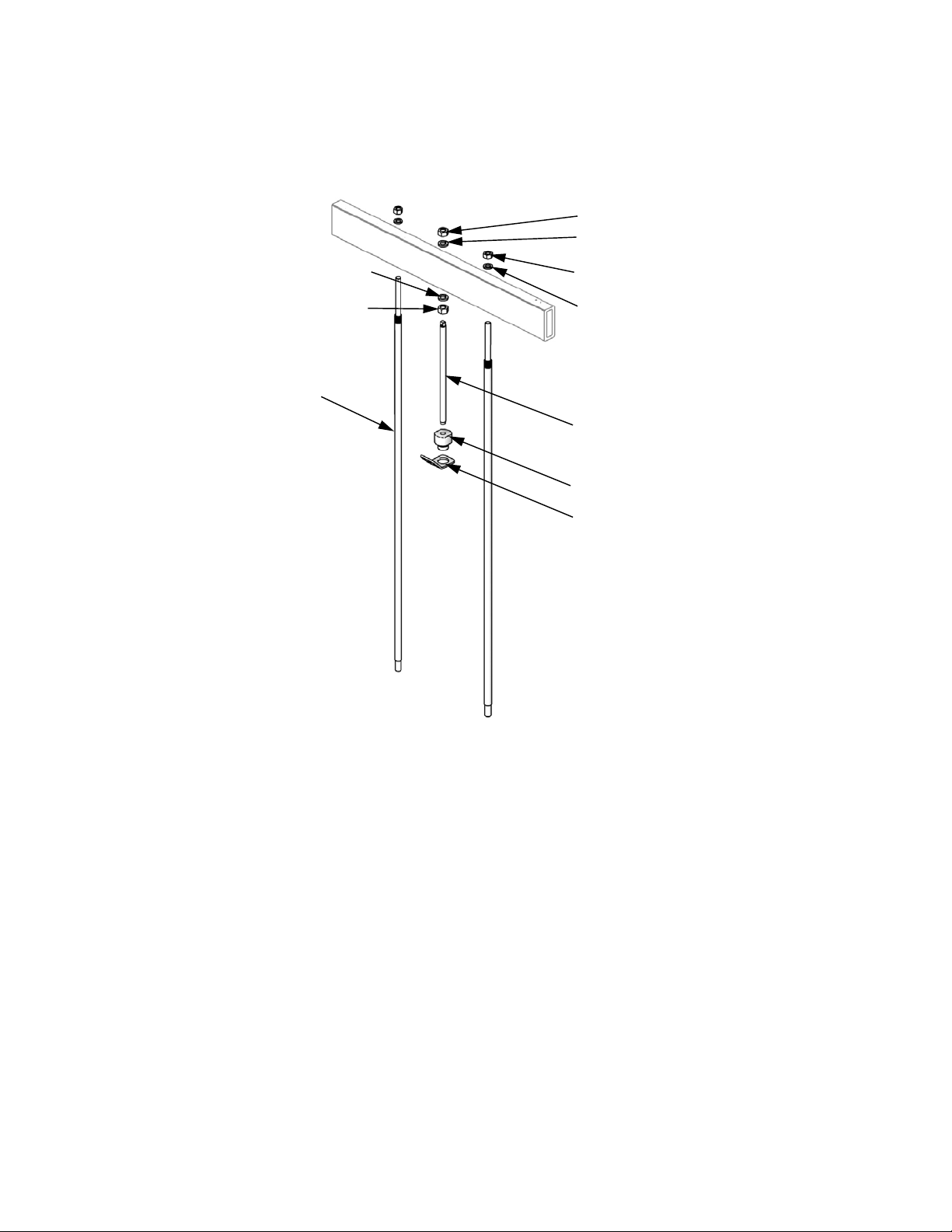
Parts
D200s and D200 Pump Mounts for 55 Gallon (200 Liter) Platen
Note: See page 38 for kit configuration table.
305
304
301
304
305
303, 305
302, 304
126
127
128
TI10771A
Ref. Part Description Qty
301 15M531 ROD, platen 2
167652
302 101015 WASHER, lock 2
303 C19187 NUT, hex 2
304 101533 WASHER, spring lock 2
305 101535 NUT, full hex 2
126 15J992 ROD, threaded 1
127 15J991 ADAPTER, lift, ring 1
44 3A6331G
Ref. Part Description Qty
128 15J993 RING, lift, plate 1
324 160327 FITTING, 3/4 nptf x 3/4 npsm, 90° 1
325 C12034 HOSE, coupled; 72 in. 1
326 552071 SLEEVE, protective, 6 ft 1
327 105281 FITTING, 3.4 nptf x 3/4 npsm, 45° 1
Not shown.
Page 45

D60 Pump Mount 257624 for 5 Gallon (20 Liter) Platen
Note: See page 38 for kit configuration table.
383
382
381
Parts
384
Ref. Part Description Qty.
381 BRACKET, shelf, NXT3400 and
NXT6500
382 101533 WASHER, spring lock 2
383 101535 NUT, hex 2
384 100133 WASHER, lock 4
385 C38372 SCREW, cap, hex head 4
388 SLEEVE, protective; 72 in. 1
389 STRAP, tie 2
390 HOLDER, cable tie, rotating 2
391 160327 FITTING, 3/4 nptf x 3/4 npsm, 90° 1
For 257624 only.
Not shown.
385
1
3A6331G 45
Page 46

Parts
Transformer
6.5 in. Ram Transformer Kit 25E202
Tighten u-bolt nuts until lock
1
washers are flattened.
Over-tightening may damage
ram cylinder.
511
1
509
510
508
513
514
517
520
3 in. Ram Transformer Kit 25E203
515
515
516
513
502
501
514
520
517
516
518
512
507
523
506
515
519
504
521,522
505
525
519
503
524
523
525
46 3A6331G
Page 47

Transformer Parts
Ref.
No. Part No. Description Qty.
501* 16A566 BRACKET, mounting, ram, 3 in. 2
502* 17X839PKG BRACKET, mounting, xformer, 3 in.
ram, painted
503* 100015 NUT, hex mscr 8
504* 100014 SCREW, cap, hex hd 8
505* 100016 WASHER, lock 8
506** 100101 SCREW, cap, hex hd 4
507** C19200 WASHER, plain 4
508** 100131 NUT, full hex 4
509** C32424 BOLT, u, 7 in. 2
510** 617395 CLAMP, saddle 2
511** 100133 WASHER, lock, 3/8 8
512** 17X836 BAR, xformer mounting, 6 in. ram,
painted
513 17D989 CONNECTOR, conduit, liquid-tight 1
514 120800 CONDUIT, 1/2 1
515 17D987 CONNECTOR, conduit, liquid-tight 1
516 129626 TRANSFORMER, 480V 1
517 16K918 LABEL, power in, branch circuit 1
518 196548 LABEL, caution 1
519 107530 SCREW, cap, sch, hex 4
520 25E178 LABEL, safety, danger 1
521 124436 CONNECTOR, splice, wire 2
522 124437 CAP, splice, wire 2
523 065388 WIRE, copper, electric 1
524 124443 TERMINAL, ring, insulated, 1/4 1
525 127667 FERRULE 2
Parts
2
1
* Parts only included in kit 25E202.
** Parts only included in kit 25E203.
Replacement safety labels, tags, and cards are
available at no cost.
3A6331G 47
Page 48

Parts
Cable Track
809
808
811(x3)
816(x4)
810
807
806
812
814(x4)
805
804
815
813(x4)
811(x3)
Cable Tracks, 25E346, 25E347, and 25E348
Quantity
Ref Part Description 25E346 25E347 25E348
801 C12509 TUBE, nylon, rnd
802 128986 CONNECTOR, 2 conductor, leverlock
131795 CORD, power, d60
803
804 121003 CABLE, can, female / female 3.0 m
805 124415 CABLE, 5pin, mf, 3.0 m, molded
806
807 17X897PKG CABLE, track, igus, d60, e-drive
808 128177 INSERT, rubber, cord grip, 4 x 6 mm
809 128397 INSERT, rubber, cord grip, 9-10 mm
810 131664PKG FRAME, cord grip, 2-position
811 C38321 TIE, cable, 3.62 lg
812 17Y316PKG COVER, disconnect, painted
813 104572 WASHER, lock spring
814 109114 SCREW, cap, sch
815 121171 GRIP, cord, .35-.63, 3/4
816 128670 BOLT, flange hd, serrated, m5, sst
131796 CORD, power, d200
131797 CORD, power, d200s
125183 CABLE, m12, 8 pin, mf, 2.5 m, molded
15Y051 CABLE, m12, 8 pin, mf, 3.0 m, molded
14 ft 15.5 ft 17.5 ft
222
1
1
1
222
111
11
1
111
111
111
111
666
111
444
444
111
444
803
801
802
48 3A6331G
Page 49

55 Gallon Platen
Parts
200 Liter (55 Gallon) Platen, 255662, 255663,
and 255664
408
*426
*427
*428
416
403
417
421
414
ti20583a
200 Liter (55 Gallon) Platen with EPDM Hose
Wipers, 24Y343
*428
*426
*427
414
408
409
403
421
416
417
410
WLD
200 Liter (55 Gallon) Platen Parts
Ref. No.Part No. Description Qty.
403 257697 HANDLE, bleed assy 1
408 255652 SEAL, wiper, drum, 55 gal., neo-
prene; for 255664 only.
255653 SEAL, wiper, drum, 55 gal., EPDM;
for 255663 and 255662 only.
414 PLATE, ram 55 gal., for 255664
and 255663 only.
PLATE, ram 55 gal., PTFE 1
416 122056 VALVE, check, 1/4, for 255662 and
255663 only
501867 VALVE, check, 5/8, for 255664 only 1
417 17E556 FITTING, PTC, elbow,1/4 NPT, 1/4
TUBE
421 15W032 ADAPTER, for 255663, 255664,
and 25N344
16W974 ADAPTER, for 255662 only 1
426* 102637 SCREW, cap 4
427* 276025 CLAMP 4
428* 109495 O-RING 1
* Parts included in 255392 Kit (purchase separately).
Parts not included with 255662, 663, and 664.
200 Liter (55 Gallon) Platen with EPDM Hose
Wipers Parts
Ref.
2
No. Part No. Description Qty.
2
403 257697 HANDLE, bleed assy 1
408† 17L889 SEAL, wiper, drum, 55 gal., EPDM 1
1
409† 162230 SEAL, wiper, drum, 55 gal., EPDM 1
410† 17B467 CLAMP, tire 4
414 PLATE, ram 55 gal. 1
416 122056 VALVE, check, 1/4 1
1
417 17E556 FITTING, PTC, elbow,1/4 NPT, 1/4
TUBE
421 15W032 ADAPTER 1
1
426* 102637 SCREW, cap 4
427* 276025 CLAMP 4
1
428* 109495 O-RING 1
* Parts included in 255392 Kit (purchase separately).
† Parts included in 25M210 Kit (purchase separately).
Parts not included with 24Y343.
1
Parts not included with 25N344.
3A6331G 49
Page 50

Parts
20 Liter (5 Gallon), 30 Liter (8 Gallon), and 60 Liter (16 Gallon) Platens
Double Wiper Platen
461
451
456
457
453
452
453
459
462
464
461
465
459
Single Wiper with
SST Platen
456
459
457
452
460
470
464
451
469
459
465
Single Wiper Platen
470
461
462
451
456
459
457
452
469
459
462
465
464
Single Wiper Platen
PVC
461
456
459
457
453
452
459
462
451
465
464
454
453
454
455
455
r_255648_313527_25a
r_255648_313527_34a
FIG. 35: Single and Double Wiper Assemblies
453
454
455
r_255648_313527_26a
454
455
50 3A6331G
Page 51

Platen Descriptions
Parts
Platen Platen Size
257727
257728
257729
257730
257731
25A206
25E110
257732
257733
257734
257735
257736
257737
257740
257738
257739
257741
20 Liter
(see page 52)
30 Liter
(see page 52)
60 Liter
(see page 54)
Platen
Material
CS Nitrile 257639
CS PolyUrethane 257640
SST PTFE-coated
CS Nitrile 257642
CS PolyUrethane 257643
SST Nitrile (FDA
CS PVC 25E111
CS Nitrile 257644
CS PolyUrethane 257645
SST PTFE-coated
CS Nitrile 257647
CS PolyUrethane 257648
CS Nitrile 257649
CS PolyUrethane 257650
SST PTFE-coated
CS Nitrile 257652
CS PolyUrethane 257653
Seal
Material Wiper Assembly Kit
Nitrile
Approved)
Nitrile
Nitrile
257641
25A207
257646
257651
Single wiper
Double wiper
See page 52-54 for parts.
3A6331G 51
Page 52

Parts
Common Parts
The parts listed below are common among all 20, 30,
and 60 liter platens. Parts that vary are found in the
tables on page 52-54.
Ref. Part Description Qty.
456 121829 O-RING 1
459 555413 NUT, (For SST platens) 12
113504 NUT, keps, hex hd (For CSTL platens) 12
461 257697 HANDLE, bleed, sst 1
463 109482 O-RING; see page 54 1
465 17E556 FITTING, PTC, elbow,1/4 NPT, 1/4
TUBE
Varying Parts - 20 Liter (5 Gallon) Platens
The following table indicates which parts (according to reference number) are included with each platen.
Reference Numbers
Ref. Description
451 BASE 257665 257665 257662 257665 257665 257662 257665
SPACER 276049 276049 276049 257694 257694 276049 17T370
452‡
WIPER, main 257672 257678 257675 257672 (2) 257672 (2) 25A208 15W597
453‡
WIPER, PE support 257681 257681 257681 257681 257681 257681 17T371
454‡
PLATE, bottom 257668 257668 257671 257668 257668 257671 257668
455‡
PLATE, top - clamp retainer 257692 257692 257698 257686 257686 257698 C31154 (2)
457‡
WIPER, support 257689 n/a
460‡
SCREW, cap, hex hd 100057 100057 112894 100057 100057 112894
462‡
464 VALVE, check 122056 122056 501867 122056 122056 501867 122056
TAG, instructions n/a n/a n/a n/a n/a
468‡
COVER 15W184 15W184 15W184 15W184
469‡
PIN, hairpin, cotter (10 pack) 16U740 16U740 16U740 16U740
470‡
1
Qty:257727 257728 257729 257730 257731 25A206 25E110
1
1
1 (2)
1
1
1 (2)
1
2
1
1
1
2
Parts designated n/a are not available separately. ‡ See page 51 for wiper assembly kits.
Varying Parts - 30 Liter (8 Gallon) Platens
The following table indicates which parts (according to reference number) are included with each platen.
Reference Numbers
Ref.
451 BASE 257665 257665 257662 257665 257665
SPACER 194148 194148 194148 257695 257695
452‡
WIPER, main 257673 257679 257676 257673 (2) 257679 (2)
453‡
WIPER, PE support 257682 257682 257682 257682 257682
454‡
PLATE, bottom n/a n/a n/a n/a n/a
455‡
PLATE, top n/a n/a n/a n/a n/a
457‡
WIPER, support 257690
460‡
SCREW, cap, hex hd 100057 100057 112894 100057 100057
462‡
VALVE, check 122056 122056 501867 122056 122056
464
TAG, instructions n/a n/a n/a
468‡
COVER 15X403 15X403 15X403
469‡
PIN, hairpin, cotter (10 pack) 16U740 16U740 16U740
470‡
Qty:Description 257732 257733 257734 257735 257736
1
1
1 (2)
1
1
1
1
2
1
1
1
2
52 3A6331G
Page 53

Parts designated n/a are not available separately.
‡ See page 51 for wiper assembly kits.
Parts
3A6331G 53
Page 54

Parts
Varying Parts - 60 Liter (16 Gallon) Platens
The following tables indicates which parts (according to reference number) are included with each platen.
Reference Numbers
Ref.
451 BASE 257665 257665 257662 257665 257665
SPACER 257684 257684 257684 257696 257696
452‡
WIPER, main 257674 257680 257677 257674 (2) 257680 (2)
453‡
WIPER, PE support 257683 257683 257683 257683 257683
454‡
PLATE, bottom n/a n/a n/a n/a n/a
455‡
PLATE, top n/a n/a n/a n/a n/a
457‡
WIPER, support 257691
460‡
SCREW, cap, hex hd 100057 100057 112894 100057 100057
462‡
464 VALVE, check 122056 122056 501867 122056 122056
TAG, instructions n/a n/a n/a
468‡
COVER 15X404 15X404 15X404
469‡
PIN, hairpin, cotter (10pack) 16U740 16U740 16U740
470‡
Parts designated n/a are not available separately. ‡ See page 51 for wiper assembly kits.
Platen Mounting Kits
Check-Mate Mounting
Dura-Flo SS Mounting Kit 257630
Dura-Flo CS Mounting
Qty:Description 257737 257740 257738 257739 257741
1
1
1 (2)
1
1
1
1
2
1
1
1
2
471
472
462
463
473
471
472
462
463
r_255648_313527_35a
r_255648_313527_36a
462
473
Ref. Part Description Qty.
463 109482 O-RING 1
471 ADAPTER 1
472 SCREW, socket-hd 2
473 109458 O-RING 1
54 3A6331G
Page 55

Kits and Accessories
Kits and Accessories
Accessories are available from Graco. Make certain all
accessories are adequately sized and pressure-rated to
meet the system’s requirements.
Drum Roller Kits for D200 and D200S Supply Units, 255627
See the Drum Roller Kit manual for more information.
Drum Position Clamp Set for D200 Supply Units, 206537
Includes two clamps.
Drum Position Clamp for D200S Supply Units
Order quantity 2 of C32463.
Enclosed Wet Cup Recirculation Kit
See the Enclosed Wetcup Recirculation Kit manual for
more information.
200 Liter (55 Gallon) Platen Cover Kits, 255691
ADM Kit, 25E437
Part Description Qty.
24E451 MODULE, gca, adm
124415 CABLE, 5 pin
261105 TIE, cable
15M121 TOKEN, gca, key
CAN Cables
The following CAN cables and splitter are available for
use with E-Flow SP electric pumps.
Part Description Length
125306 CABLE, CAN, female/female
123422 CABLE, CAN, female/female
121000 CABLE, CAN, female/female
121227 CABLE, CAN, female/female
121001 CABLE, CAN, female/female
121002 CABLE, CAN, female/female
121003 CABLE, CAN, female/female
120952 CABLE, CAN, female/female
121201 CABLE, CAN, female/female
121004 CABLE, CAN, female/female
121228 CABLE, CAN, female/female
123341 CABLE, CAN, female/female
121807 CONNECTOR, splitter, male/male
0.3 m
0.5 m
0.5 m
0.6 m
1.0 m
1.5 m
3.0 m
4.0 m
6.0 m
8.0 m
15.0 m
40.0 m
See the Platen Cover Kit manual for more information.
I/O Cable, 122029
Light Tower Kit, 255468
For D200s, D200, and D60 single supply systems.
See the Light Tower Kit manual for more information.
3A6331G 55
See the E-Flo SP Software Instructions manual for
setup and pin out information.
Part Description Length
122029 CABLE, GCA, M12-8p
15.0 m
Page 56

Kits and Accessories
Communication Gateway Module (CGM) Kits
4. Drill the mounting holes using the mounting hole
dimensions shown in FIG. 37.
#10-32 UNF
(M5 x 0.8)
2.75 in.
(69.9 mm)
CAN Port 2
CAN Port 1
FIG. 36: CGM CAN Connections
CGM Kits
Part Number Description
25E426 CGM Kit, Ethernetip
25E427 CGM Kit, DeviceNet
25E428 CGM Kit, PROFINET
25E429 CGM Kit, PROFIBUS
Installing a CGM Kit
All electrical wiring must be done by a qualified electrician and comply with all local codes and regulations
3.25 in.
(82.6 mm)
FIG. 37: CGM Mounting Holes
5. Remove the access cover from the CGM (CA).
Loosen the two screws (CB) and remove the CGM
(CC) from the base (CD) as shown in FIG. 38.
CB
CC
CA
CD
1. Follow the Pressure Relief Procedure on page 22.
2. Verify the power is off to the system.
3. Mount the CGM near the pump or near the integration point.
56 3A6331G
FIG. 38: Disassembling the CGM
6. Using the four 10-32 mounting screws included with
the kit, mount the base (CD) in the holes you drilled.
7. Reattach the CGM (CC) on the base (CD) with the
two screws (CB) that were removed in step 5.
8. Reattach the access cover (CA).
Page 57

Kits and Accessories
9. Connect the CAN cable included in the kit to either
port 1 or port 2 (whichever is available) on the
driver. See FIG. 39.
Port 1
Port 2
Port 6
FIG. 39: Driver Port Locations
10. Connect the other end of the CAN cable to either
CAN port 1 or 2 on the CGM. See FIG. 36. It can be
connected to either port.
NOTE: Longer CAN cables, if required, are available
from Graco. See CAN Cables on page 55.
11. Connect the Ethernet, DeviceNet, or PROFIBUS
cable to the fieldbus connection on the CGM as
applicable. See FIG. 40.
Fieldbus
Connection
FIG. 40: CGM Fieldbus Connection
12. Connect the other end of the cable to the fieldbus
device.
13. Refer to the Graco Control Architecture Module Programming manual for step-by-step instructions on
how to update the software version of GCA modules. See Related Manuals on page 3.
14. Refer to the E-Flo SP Software Instructions manual
for details regarding the fieldbus pinout setup and to
perform the setup procedure to configure the fieldbus. See Related Manuals on page 3.
3A6331G 57
Page 58

Kits and Accessories
Low Level Sensor Kit, 25E447
To install the Low Level Sensor:
1. Turn the disconnect switch (M) OFF.
2. Disconnect cable from the empty level sensor (EL).
3. Mount the low level sensor (LL) on the mounting
bracket.
4. Connect the shorter cable to the low level sensor
(LL).
5. Connect the other shorter cable to the empty level
sensor (EL).
6. Connect the low level sensor cable to the A port on
the splitter (SP).
7. Connect the empty level sensor cable to the B port
on the splitter (SP).
8. Connect the original cable to the last port on the
splitter (SP).
SP
LL
SP
9. Raise/lower the low level sensor (LL) to the desired
position to activate the sensor.
10. See the E-Flo SP Software Instructions manual to
set up the low level sensor.
EL
58 3A6331G
Page 59

Kits and Accessories
Tandem Connection Kit, 25E595
Ref. Part Description Qty.
501 121226 CABLE, can, 0.4 m 1
502 124003 CABLE, can, 5.0 m 1
503 121003 CABLE, can, 3.0 m 1
504 121807 CONNECTOR, splitter 1
505 114958 STRAP, tie 3
506 117329 STRAP, tie 6
To install the Tandem Connection Kit:
1. On the primary tandem unit (Ram 1), connect the
cable (501) from port C1 to the splitter (504).
Ram 1
Ram 2
2. Connect the other cable (503) from the splitter to the
ADM. Run the cable along the back of the ram using
wire ties (505) to secure to the tubing.
Ram 1
504
503
503
505
3. Connect the cable (502) from the splitter to port C2
on the secondary tandem unit (Ram 2) junction box.
Ram 1
504
504
Ram 1
501
502
Ram 2
Port C1
502
4. See the E-Flo SP Software Instructions manual for
system setup.
3A6331G 59
Page 60
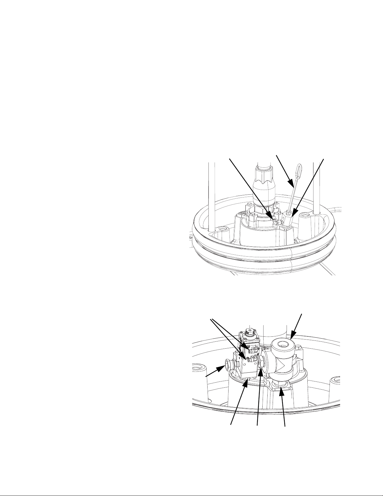
Kits and Accessories
Tandem Depressurization/Recirculation Kit, 25E618 (carbon steel), 25E619 (stainless steel)
To assemble the Tandem
Ref. Part Description Qty.
601 C20487 FITTING, nipple, hex (25E618 only) 1
190724 NIPPLE, sst (25E619 only)
602 132019 FITTING, tee, 3/4 npt (25E618
only)
15M862 FITTING, tee, pipe (25E619 only)
604 15B556 FITTING, adapter, 1/4 npt x 3/4 npt 1
605 114582 ADAPTER, swivel, straight
(25E618 only)
15M859 FITTING, adapter, male, swivel
(25E619 only)
606 054753 TUBE, nylon, black 22.5 ft
607 25R844 VALVE, 25, npt/b,000rm,amb,5k 1
609 255722 HOSE, coupled, hp (25E618 only) 1
255725 HOSE, coupled, hp, sst (25E619
only)
610 517434 FITTING, tee, 1/2 npt 1
613 15M574 VALVE, solenoid 1
614 117820 SCREW, cap, socket hd 2
615 198178 FITTING, elbow 3
616 17Z412 BRACKET, valve, solenoid 1
617 107100 SCREW, cap 2
618 18A098
PKG
619 116504 FITTING, tee 1
620 070408 SEALANT, pipe, sst 1
621 114958 STRAP, tie 4
624 114151 FITTING, elbow, male, swivel 2
HARNESS, solenoid, tandem 1
Depressurization/Recirculation Kit:
1. Disconnect the air line from the air assist body check
1
1
valve (EH)
2. Remove the bleed stick (EF) and bleed port (EG).
Save all parts for later.
3. Assemble the fittings and valve onto the platen as
shown below.
.
EH
EF
EG
624
605
607
60 3A6331G
604
602
601
Page 61

Kits and Accessories
4. Assemble the bleed port (EG) and bleed stick (EF)
to the cross fitting (602).
EF
EG
602
5. Mount the solenoid mounting plate (616) to the side
of the driver using the supplied screws (617).
7. Connect the cable (618) from the solenoid (613) to
Port 4 on the driver.
Port 4
613
618
8. Remove the adapter and pressure transducer from
the bottom of the check valve block.
Check
Valve Block
617
616
6. Mount the solenoid (613) to the solenoid mounting
plate (616) with the supplied screws (614).
616
613
614
Pressure
Transducer
9. Connect the tee fitting (614) to replace the adapter
and pressure transducer removed in the previous
step.
614
3A6331G 61
Page 62

Kits and Accessories
10. Looking at the valve check block from the front,
connect the adapter and pressure transducer that
were removed in step 8 to the connection on the
right side of the tee fitting (610). Connect a union
adapter fitting (605) to the other side of the tee
fitting.
11. Connect the hose (609) between the fitting (605)
above to the fitting (605) in the valve.
605
610
609
Adapter and
Pressure
Transducer
605
13. Install the air line (606) from the integrated air
control module (G), along the back of the ram,
through the cable track and to the solenoid (613).
G
606
606
12. Install the fittings (611, 615) on the back of the
integrated air control module (G).
606
619
G
613
615
606
62 3A6331G
Page 63

14. Install the air line (606) from the lower solenoid
outlet to the valve close fitting (615). Cut any excess
air line.
15. Install the air line (606) from the upper solenoid
outlet to the valve open fitting (615). Cut any excess
air line.
Kits and Accessories
Upper Solenoid
Outlet
Lower Solenoid
Outlet
606
606
624, Valve Open
624, Valve Close
16. See the E-Flo SP Software Instructions manual for
Depressurization/Recirculation setup.
3A6331G 63
Page 64

Kits and Accessories
Tandem Fluid Filter Kit, 25E620
Fluid Inlet from
Tandem A
714
708
712
713
722
723
706
725
Fluid Inlet from
Tandem B
715,
716,
717
724
718,
719,
720
703
702
Fluid Outlet
704
710
709
711
707
Ref. Part Description Qty.
701 247498 SUPPORT, stand 1
702 410178 CAP PLUG, vinyl 1
703 147499 BASE, mounting 1
704 C30021 BOLT, u 2
705 210658 VALVE, ball 1
706 515216 HOUSING, filter 1
707 C19652 FITTING, bushing, reducing 2
708 121189 FITTING, elbow, 1” 2
709 521477 VALVE, ball, 1” 3
710 121182 ADAPTER, pipe, female 2
711 102814 GAUGE, press, fluid 2
712 C19488 FITTING, tee 1
713 121163 FITTING, cross, 1” npt 2
714 131526 FITTING, nipple, 1” npt, cs 6
715 101044 WASHER, plain 4
716 100018 WASHER, lock, spring 4
717 C19853 SCREW, cap, socket hd 4
718 100023 WASHER, flat 4
719 100133 WASHER, lock, 3/8 4
720 100131 NUT, full hex 4
721 070408 SEALANT, pipe, sst 1
722 158586 FITTING, bushing 2
723 16U440 ADAPTER, fitting, pressure sensor 2
724 15M669 SENSOR, pressure, fluid outlet 2
725 515222 ELEMENT, filter 1
726 15Y048 CABLE, M12 2
705
701
To assemble the Tandem Fluid Filter Kit:
1. Ensure the base of the fluid filter stand (701) is level
in all directions. If necessary, use metal shims to
level the base.
2. Secure the base to the floor using anchors that are
long enough to prevent the filter stand from tipping.
3. Install the material hose from tandem A to fluid inlet
A.
4. Install the material hose from tandem B to fluid inlet
B.
5. Install the material hose from the fluid filter outlet to
the dispense valve.
6. Connect the inlet fluid filter pressure transducer to
Port 6 on the tandem A driver for fluid filter
monitoring.
64 3A6331G
Page 65

Kits and Accessories
7. Connect the inlet fluid filter pressure transducer to
port 6 on the tandem B driver for fluid filter
monitoring.
a. Available extension cables are shown in the
table below.
Part Description
122497 CABLE, M12, 5 pin, 2 m
124409 CABLE, M12, 5 pin, 3 m
124943 CABLE, M12, 5 pin, 1 m
17H363 CABLE, M12, 5 pin, 7.5 m
17H364 CABLE, M12, 5 pin, 16 m
8. See the E-Flo SP Software Instructions manual to
set up fluid filter monitoring on the ADM.
Fluid Filter Kit Dimensions
F
G
A
B
C
E
D
Key
A 52.25 in. (1327 mm)
B 11 in. (279 mm)
C 14 in. (356 mm)
D 17 in. (432 mm)
E 14 in. (356 mm)
F 1 in. npt(f)
G 1 in. npt(f)
Filter Element Mesh Sizes
Part No. Mesh
515219 60
515220 50
515221 40
515222 30 (standard)
TI11158A
3A6331G 65
Page 66

Kits and Accessories
Notes:
66 3A6331G
Page 67

Dimensions
Dimensions
D200
B
C
F
E
G
D
B
C
G
E
D200s
F
D
D60
B
C
F
G
E
3A6331G 67
D
Page 68
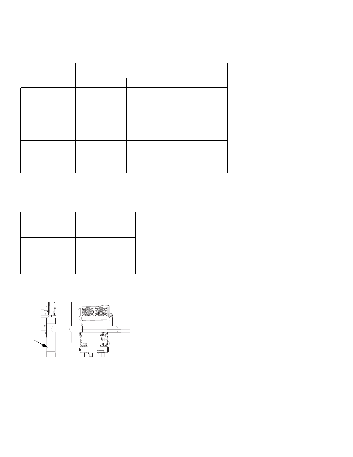
Dimensions
Dimensions
Ram Size
in. (mm)
D60 D200 D200s
Total Height (A) 70 (1778) 88 (2235) 96 (2438)
Ram Height (B) 57 (1448) 70 (1778) 69 (1753)
Extended Ram
Height (C)
Base Depth (D) 20 (508) 25 (635) 25 (635)
Machine Width (E) 45 (1143) 52 (1321) 45 (1143)
Mounting Hole
Depth (F)
Mounting Hole
Width (G)
89 (2261) 118 (2997) 125 (3175)
14 (356) 21 (533) 23 (584)
24 (610) 38 (965) 45 (1143)
Weight
Use the table below to identify the maximum weight for
each available platen size.
Platen Size
Gallons (Liters) Maximum Weight
55 (200)
30 (115)
16 (60)
8 (30)
5 (20)
See the identification plate (ID) for the weight of your
supply system.
ID
51 (23)
44 (20)
25 (11.3)
21 (9.5)
19 (8.7)
68 3A6331G
Page 69

Pump Performance
Pump Performance
Calculate Fluid Outlet Pressure
To calculate fluid outlet pressure (psi/MPa/bar) at a
specific fluid flow (gpm/lpm) and electrical power (W),
use the following instructions and pump data chart.
1. Refer to the desired flow along the bottom of the
chart.
2. Follow the vertical line up to the intersection with the
selected fluid outlet pressure curve. Follow left to
the scale to read the fluid out pressure.
Calculate Electrical Power
To calculate electrical power (W) at a specific fluid flow
(gpm/lpm), use the following instructions and pump data
chart.
1. Refer to the desired flow along the bottom of the
chart.
2. Follow the vertical line up to the intersection with the
selected electrical power curve. Follow right to the
scale to read the fluid out pressure.
NOTE: Performance is measured using 10 weight oil.
System design and material being pumped may
produce different results.
3A6331G 69
Page 70
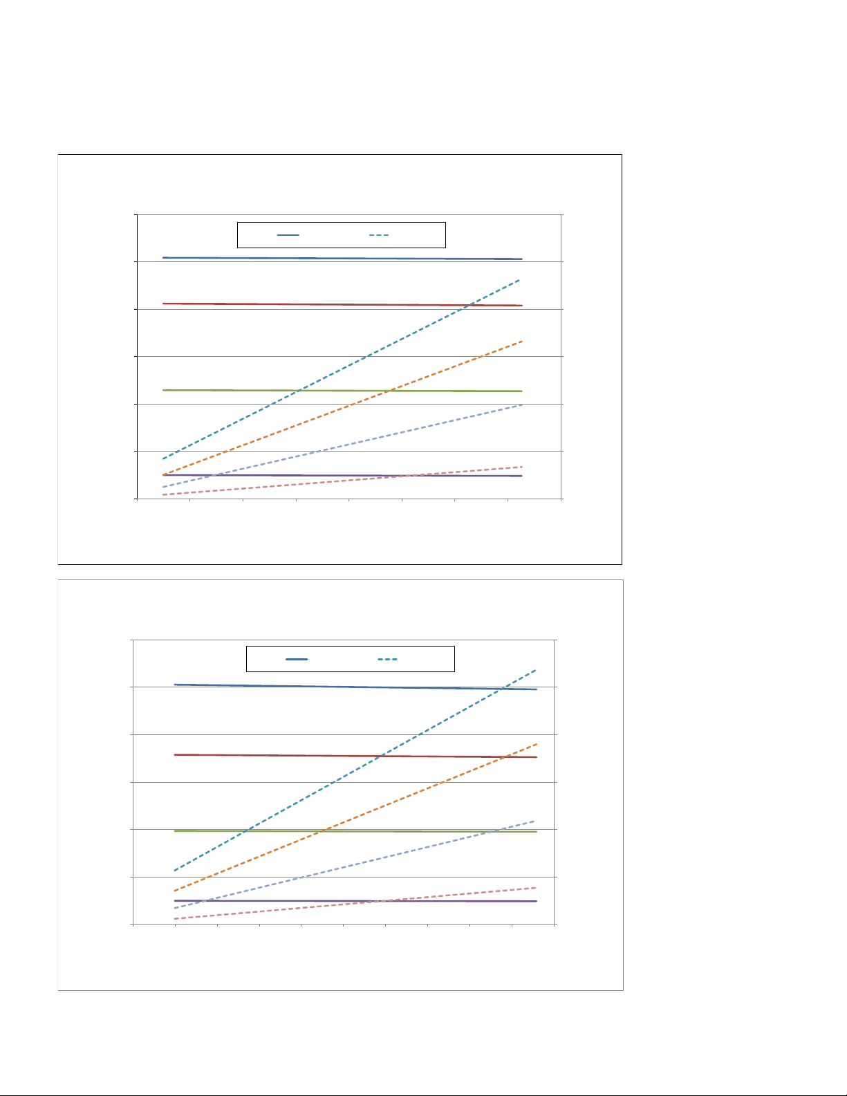
Pump Performance
E-Flo SP Performance Charts
&'MP41%SJWFSXJUI%VSB'MP-PXFS
6000
(41.4, 414)
5000
(34.5, 345)
4000
(27.6, 276)
3000
(20.7, 207)
2000
1SFTTVSFQTJ.1BCBS
(13.8, 138)
1000
(6.9, 69)
0 (0, 0)
0.0 0.1 0.2 0.3 0.4 0.5 0.6 0.7 0.8
(0.0) (3.0)(2.6)(2.3)(1.9)(1.1)(0.8)(0.4)
3000
Pressure WŽǁĞƌ
2500
2000
1500
1PXFS8BUUT
1000
500
0
(1.ϱ)
'MPXHQNMQN
&'MPX41XJUI%VSB'MP-PXFS
6000
(41.4, 414)
5000
(34.5, 345)
4000
(27.6, 276)
3000
(20.7, 207)
2000
1SFTTVSF QTJ.1BCBS
(13.8, 138)
1000
(6.9, 69)
0 (0, 0)
0.0 0.1 0.2 0.3 0.4 0.5 0.6 0.7 0.8 0.9 1.0
(0.0) (0.4) (0.8) (1.1) (1.5) (1.9) (2.3) (2.6) (3.0) (3.8)(3.4)
3000
Pressure WŽǁĞƌ
2500
2000
1500
1PXFS8BUUT
1000
500
0
'MPXHQNMQN
70 3A6331G
Page 71

Pump Performance
NOTE: Performance is measured using 10 weight oil. System design and material being pumped may produce
different results.
3A6331G 71
Page 72

Pump Performance
&'MPX41XJUI%VSB'MP-PXFS
5000
(34.5, 345)
4000
(27.6, 276)
3000
(20.7, 207)
2000
(13.8, 138)
1SFTTVSF QTJ.1BCBS
1000
(6.9, 69)
0 (0, 0)
0.0 0.2 0.4 0.6 0.8 1.0 1.2
(0.0) (0.8) (1.5) (2.3) (3.0) (3.8) (4.5)
Pressure WŽǁĞƌ
'MPXHQNMQN
3500
2800
2100
1400
700
0
1PXFS8BUUT
&'MPX41XJUI%VSB'MP-PXFS
4000
(27.6, 276)
3500
(24.1, 241)
3000
(20.7, 207)
2500
(17.2, 172)
2000
(13.8, 138)
1500
(10.3, 103)
1SFTTVSF QTJ.1BCBS
1000
(6.9, 69)
500
(3.4, 34)
0 (0, 0)
0.0 0.2 0.4 0.6 0.8 1.0 1.2
(0.0) (0.8) (1.5) (3.0) (3.8) (4.5)
Pressure WŽǁĞƌ
(Ϯϯ)
'MPXHQNMQN
3000
2625
2250
1875
1500
1PXFS8BUUT
1125
750
375
0
NOTE: Performance is measured using 10 weight oil. System design and material being pumped may produce
different results.
72 3A6331G
Page 73

&'MPX41XJUI%VSB'MP-PXFS
Pump Performance
3000
(20.7, 207)
2500
(17.2, 172)
2000
(13.8, 138)
1500
(10.3, 103)
1SFTTVSF QTJ.1BCBS
1000
(6.9, 69)
500
(3.4, 34)
0 (0, 0)
0.0 0.5 1.0 1.5 2.0
(0.0) (1.9) (5.7) (7.6)
4500
Pressure WŽǁĞƌ
3750
3000
2250
1PXFS8BUUT
1500
750
0
(ϯϴ)
'MPXHQNMQN
&'MPX41XJUI%VSB'MP-PXFS
2000
(13.8, 138)
1750
(12.1, 121)
1500
(10.3, 103)
1250
(8.6, 86)
1000
(6.9, 69)
750
(5.2, 52)
1SFTTVSF QTJ.1BCBS
500
(3.4, 34)
250
(1.7, 17)
0 (0, 0)
0.0 0.5 1.0 1.5 2.0 2.5
(0.0) (1.9) (3.8) (7.6) (9.5)
Pressure WŽǁĞƌ
(5.7)
'MPXHQNMQN
NOTE: Performance is measured using 10 weight oil. System design and material being pumped may produce
different results.
3000
2625
2250
1875
1500
1PXFS8BUUT
1125
750
375
0
3A6331G 73
Page 74

Pump Performance
&'MPX41XJUI$IFDLNBUF-PXFS
6000
(41.4, 414)
5000
(34.5, 345)
4000
(27.6, 276)
3000
(20.7, 207)
2000
1SFTTVSFQTJ.1BCBS
(13.8, 138)
1000
(6.9, 69)
0 (0, 0)
0.0 0.1 0.2 0.3 0.5 0.6 0.7 0.8
Pressure WŽǁĞƌ
0.4
(1.ϱ)
'MPXHQNMQN
2400
2000
1600
1200
1PXFS8BUUT
800
400
0
(3.0)(2.6)(2.3)(1.9)(1.1)(0.8)(0.4)(0.0)
4500
(31.0, 310)
3750
(25.9, 259)
3000
(20.7, 207)
2250
(15.5, 155)
1500
1SFTTVSFQTJ.1BCBS
(10.3, 103)
750
(5.2, 52)
0 (0, 0)
0.0 0.2 0.4 0.6 0.8 1.0 1.2
(0.0) (0.8) (1.5) (3.0) (3.8) (4.5)
&'MPX41XJUI$IFDLNBUF-PXFS
3000
Pressure WŽǁĞƌ
2500
2000
1500
1PXFS8BUUT
1000
500
0
(2.3)
'MPXHQNMQN
NOTE: Performance is measured using 10 weight oil. System design and material being pumped may produce
different results.
74 3A6331G
Page 75

&'MPX41XJUI$IFDLNBUF-PXFS
Pump Performance
3500
(24.1, 241)
3000
(20.7, 207)
2500
(17.2, 172)
2000
(13.8, 138)
1500
(10.3, 103)
1SFTTVSFQTJ.1BCBS
1000
(6.9, 69)
500
(3.4, 34)
0 (0, 0)
0.0 0.2 0.4 0.6 1.0 1.2 1.4 1.6
(0.0) (0.8) (1.5) (2.3) (3.8) (4.5) (5.3) (6.1)
Pressure WŽǁĞƌ
0.8
(3.Ϭ)
'MPXHQNMQN
2625
2250
1875
1500
1125
750
375
0
1PXFS8BUUT
1800
(12.4, 124)
1500
(10.3, 103)
1200
(8.3, 83)
900
(6.2, 62)
600
1SFTTVSF QTJ.1BCBS
(4.1, 41)
300
(2.1, 21)
0 (0, 0)
0.0 0.5 1.0 1.5 2.0 2.5 3.0
(0.0) (1.9) (3.8) (7.6) (9.5) (11.4)
&'MPX41XJUI$IFDLNBUF-PXFS
3000
Pressure WŽǁĞƌ
2500
2000
1500
1PXFS8BUUT
1000
500
0
(ϱϳ)
'MPXHQNMQN
NOTE: Performance is measured using 10 weight oil. System design and material being pumped may produce
different results.
3A6331G 75
Page 76

Technical Specifications
Technical Specifications
E-Flo SP Supply Systems
US Metric
Driver thrust 4,840 lbs 2,195 kg
Stroke length 4.75 in. 120.65 mm
Maximum fluid operating temperature 180°F 82.3°C
Maximum driver cycle rate 25 cycles per minute
Line voltage rating
Air inlet size (supply system) 3/4 npt(f)
Ambient operating temperature range (supply
system)
Displacement pump effective area See pump manual.
Wetted parts See pump manual.
Sound pressure, measured per EN ISO 11202:2010
Normal operation (dispensing) < 70 dBA
Drum change 77 dBA
Full load amperage
240V systems 20A
480V systems 10A
Maximum fluid working pressure
100cc Check-Mate - All 6000 psi 414 bar, 41.4 MPa
200cc Check-Mate - All 4200 psi 290.5 bar, 29.0 MPa
250cc Check-Mate - All 2700 psi 186.1 bar, 18.6 MPa
500cc Check-Mate - All 1600 psi 89.6 bar, 8.9 MPa
145cc Dura-Flow - SS 5600 psi 386 bar, 38.6 MPa
180cc Dura-Flow - SS 4500 psi 310 bar, 31.0 MPa
220cc Dura-Flow - SS 3700 psi 255 bar, 25.5 MPa
290cc Dura-Flow - SS 2800 psi 193 bar, 19.3 MPa
430cc Dura-Flow - SS 1900 psi 131 bar, 13.1 MPa
115cc Dura-Flow - CS 6000 psi 414 bar, 41.4 MPa
145cc Dura-Flow - CS 5600 psi 386 bar, 38.6 MPa
180cc Dura-Flow - CS 4500 psi 319 bar, 31.0 MPa
220cc Dura-Flow - CS 3700 psi 255 bar, 25.5 MPa
290cc Dura-Flow - CS 2800 psi 193 bar, 19.3 MPa
Fluid outlet size
Check-Mate 100, 200, 250 1” NPT female
Check-Mate 500 1-1/2” NPT female
Dura-Flow 115, 145, 180, 220, 290 1” NPT female
Dura-Flow 430 1-1/2” NPT female
Maximum air input pressure (supply system)
D60 - 3 in. dual post, 5 gal. (20 L) 150 psi 1.0 MPa, 10 bar
D200 - 3 in. dual post, 55 gal. (200 L) 150 psi 1.0 MPa, 10 bar
D200s - 6.5 in. dual post, 55 gal. (200 L) 125 psi 0.9 MPa, 9 bar
200-240V, 1ps, 50/60 Hz
400-480V, 1ps, 50/60 Hz
32-120°F 0-49°C
76 3A6331G
Page 77

California Proposition 65
E-Flo SP Supply Systems
US Metric
Platen wetted materials
257727, 5 gal. (20 L) Electroless nickel, polyurethane, nitrile, carbon steel,
257732, 8 gal. (30 L)
257737, 16gal. (60 L)
257728, 5 gal. (20 L) Electroless nickel, polyurethane, carbon steel, polyethylene,
257733, 8 gal. (30 L)
257740, 16gal. (60 L)
257729, 5 gal. (20 L) Stainless steel, polyurethane, PTFE coated nitrile,
257734, 8 gal. (30 L)
257738, 16gal. (60 L)
257730, 5 gal. (20 L) Electroless nickel, aramind reinforced elastomer,
257735, 8 gal. (30 L)
257739, 16gal. (60 L)
257731, 5 gal. (20 L) Electroless nickel, aramind reinforced elastomer,
257736, 8 gal. (30 L)
257741, 16gal. (60 L)
25E110, 5 gal. (20 L)
25A206, 5 gal. (20 L)
polyethylene, zinc plated carbon steel, buna, 316 sst,
17-4PH sst
nitrile, zinc plated carbon steel, buna, 316 sst 17-4PH sst
polyethylene, nitrile, PTFE, 303 sst, 304 sst, 316 sst, 17-4PH
sst
rubber-based PSA, nitrile, polyethylene, zinc plated carbon
steel, buna, 1018 carbon steel, 304 sst, 316 sst, 17-4PH sst
rubber-based PSA, polyurethane, polyethylene, nitrile, zinc
plated carbon steel, buna, 1018 carbon steel, 304 sst, 316
sst, 17-4PH sst
Electroless nickel, nitrile, carbon steel, zinc plated carbon
steel, buna, 316 sst, 17-4PH sst, aluminum, PVC
Stainless steel, polyurethane, nitrile (FDA approved),
polyethylene
California Proposition 65
CALIFORNIA RESIDENTS
WARNING: Cancer and reproductive harm – www.P65warnings.ca.gov.
3A6331G 77
Page 78

Graco Standard Warranty
Graco warrants all equipment referenced in this document which is manufactured by Graco and bearing its name to be free from defects in
material and workmanship on the date of sale to the original purchaser for use. With the exception of any special, extended, or limited warranty
published by Graco, Graco will, for a period of twelve months from the date of sale, repair or replace any part of the equipment determined by
Graco to be defective. This warranty applies only when the equipment is installed, operated and maintained in accordance with Graco’s written
recommendations.
This warranty does not cover, and Graco shall not be liable for general wear and tear, or any malfunction, damage or wear caused by faulty
installation, misapplication, abrasion, corrosion, inadequate or improper maintenance, negligence, accident, tampering, or substitution of
non-Graco component parts. Nor shall Graco be liable for malfunction, damage or wear caused by the incompatibility of Graco equipment with
structures, accessories, equipment or materials not supplied by Graco, or the improper design, manufacture, installation, operation or
maintenance of structures, accessories, equipment or materials not supplied by Graco.
This warranty is conditioned upon the prepaid return of the equipment claimed to be defective to an authorized Graco distributor for verification of
the claimed defect. If the claimed defect is verified, Graco will repair or replace free of charge any defective parts. The equipment will be returned
to the original purchaser transportation prepaid. If inspection of the equipment does not disclose any defect in material or workmanship, repairs
will be made at a reasonable charge, which charges may include the costs of parts, labor, and transportation.
THIS WARRANTY IS EXCLUSIVE, AND IS IN LIEU OF ANY OTHER WARRANTIES, EXPRESS OR IMPLIED, INCLUDING BUT NOT
LIMITED TO WARRANTY OF MERCHANTABILITY OR WARRANTY OF FITNESS FOR A PARTICULAR PURPOSE.
Graco’s sole obligation and buyer’s sole remedy for any breach of warranty shall be as set forth above. The buyer agrees that no other remedy
(including, but not limited to, incidental or consequential damages for lost profits, lost sales, injury to person or property, or any other incidental or
consequential loss) shall be available. Any action for breach of warranty must be brought within two (2) years of the date of sale.
GRACO MAKES NO WARRANTY, AND DISCLAIMS ALL IMPLIED WARRANTIES OF MERCHANTABILITY AND FITNESS FOR A
PARTICULAR PURPOSE, IN CONNECTION WITH ACCESSORIES, EQUIPMENT, MATERIALS OR COMPONENTS SOLD BUT NOT
MANUFACTURED BY GRACO. These items sold, but not manufactured by Graco (such as electric motors, switches, hose, etc.), are subject to
the warranty, if any, of their manufacturer. Graco will provide purchaser with reasonable assistance in making any claim for breach of these
warranties.
In no event will Graco be liable for indirect, incidental, special or consequential damages resulting from Graco supplying equipment hereunder, or
the furnishing, performance, or use of any products or other goods sold hereto, whether due to a breach of contract, breach of warranty, the
negligence of Graco, or otherwise.
FOR GRACO CANADA CUSTOMERS
The Parties acknowledge that they have required that the present document, as well as all documents, notices and legal proceedings entered into,
given or instituted pursuant hereto or relating directly or indirectly hereto, be drawn up in English. Les parties reconnaissent avoir convenu que la
rédaction du présente document sera en Anglais, ainsi que tous documents, avis et procédures judiciaires exécutés, donnés ou intentés, à la suite
de ou en rapport, directement ou indirectement, avec les procédures concernées.
Graco Information
Sealant and Adhesive Dispensing Equipment
For the latest information about Graco products, visit www.graco.com.
For patent information, see www.graco.com/patents.
TO PLACE AN ORDER, contact your Graco distributor, go to www.graco.com, or call to identify the nearest
distributor.
If calling from the USA: 1-800-746-1334
If calling from outside the USA: 0-1-330-966-3000
All written and visual data contained in this document reflects the latest product information available at the time of publication.
GRACO INC. AND SUBSIDIARIES • P.O. BOX 1441 • MINNEAPOLIS MN 55440-1441 • USA
Copyright 2018, Graco Inc. All Graco manufacturing locations are registered to ISO 9001.
Graco reserves the right to make changes at any time without notice.
Original instructions. This manual contains English. MM 3A6331
International Offices: Belgium, China, Japan, Korea
Graco Headquarters: Minneapolis
www.graco.com
Revision
G, February 2021
 Loading...