

Page 1
Instructions
Air–Operated
308981ZAC
Diaphragm Pumps
For fluid transfer applications. For professional use only.
Only models marked with (*) are approved for use in European explosive atmosphere
locations.
100 psi (0.7 MPa, 7 bar) Maximum Fluid Working Pressure
100 psi (0.7 MPa, 7 bar) Maximum Air Input Pressure
ACETAL, POLYPROPYLENE, AND PVDF
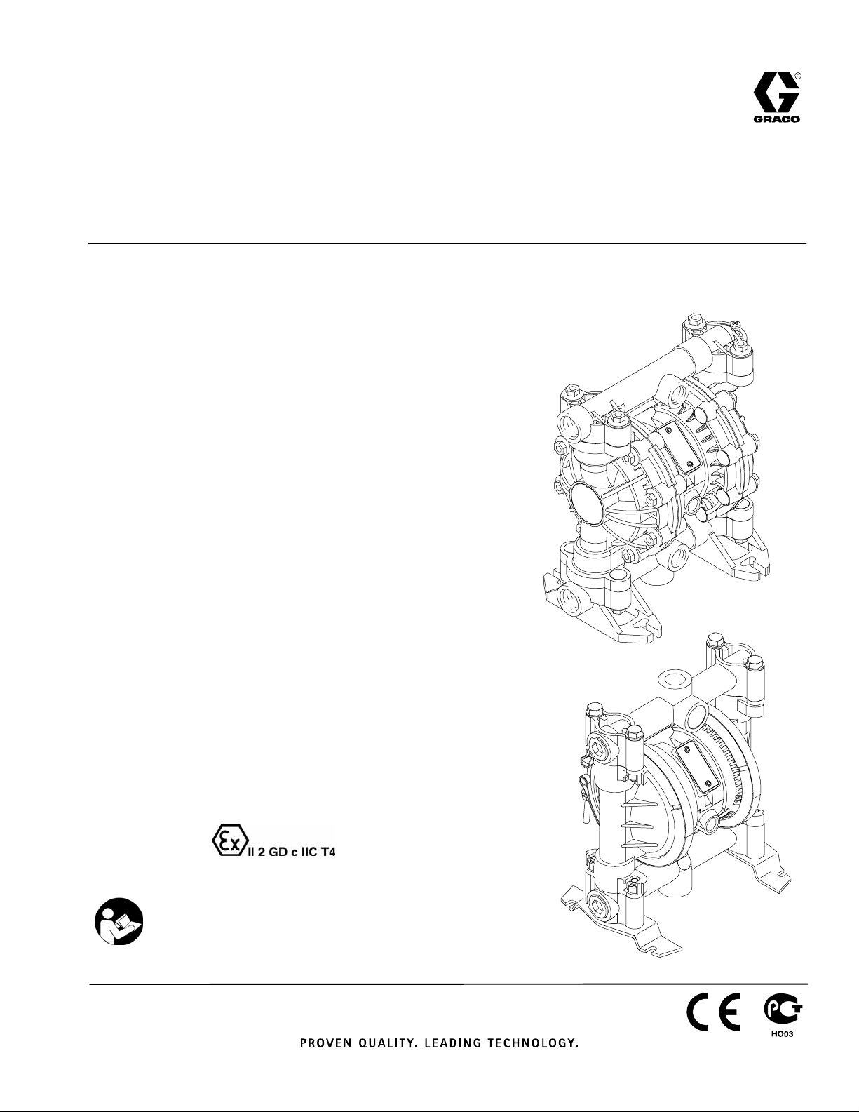
Huskyt 515
Model No. D 5 1 _ _ _ Acetal NPT Pumps*
Model No. D 5 2 _ _ _ Polypropylene Pumps
Model No. D 5 5 _ _ _ PVDF NPT Pumps
Model No. D 5 A _ _ _ Acetal BSPT Pumps*
Model No. D 5 B _ _ _ Polypropylene BSPT Pumps
Model No. D 5 E _ _ _ PVDF BSPT Pumps
For Additional Models, see Table of Contents
Husky 515
9065A
EN
ALUMINUM AND STAINLESS STEEL*
Huskyt 716
Model No. D 5 3 _ _ _ Aluminum NPT Pumps
Model No. D 5 4 _ _ _ Stainless Steel NPT Pumps
Model No. D 5 C _ _ _ Aluminum BSPT Pumps
Model No. D 5 D _ _ _ Stainless Steel BSPT Pumps
For Additional Models, see Table of Contents
*These models are certified.
Important Safety Instructions
Read all warnings and instructions in this manual.
Save these instructions.
Refer to the Pump Matrix on page 22 to determine
the model number of your pump.
9246A
Husky 716
Page 2
Table of Contents
Symbols
Safety Warnings 2. . . . . . . . . . . . . . . . . . . . . . . . . . . . . . .
Installation 4. . . . . . . . . . . . . . . . . . . . . . . . . . . . . . . . . . . . .
Operation 10. . . . . . . . . . . . . . . . . . . . . . . . . . . . . . . . . . . .
Maintenance 11. . . . . . . . . . . . . . . . . . . . . . . . . . . . . . . . . .
Troubleshooting 12. . . . . . . . . . . . . . . . . . . . . . . . . . . . . . .
Service 13. . . . . . . . . . . . . . . . . . . . . . . . . . . . . . . . . . . . . .
Husky 515 and Husky 716 Pump Matrix 22. . . . . . . . . .
Husky 515 and 715 Additional Pumps 23. . . . . . . . . . . .
Husky 515 and Husky 716 Repair Kits 22. . . . . . . . . . . .
Parts
Husky 515 and Husky 716 Common Parts 24. . . . . .
Husky 515 Parts Drawing 25. . . . . . . . . . . . . . . . . . . .
Husky 515 Fluid Section Parts List 26. . . . . . . . . . . . .
Husky 716 Parts Drawing 27. . . . . . . . . . . . . . . . . . . .
Husky 716 Fluid Section Parts List 28. . . . . . . . . . . . .
Torque Sequence 29. . . . . . . . . . . . . . . . . . . . . . . . . . . . .
Husky 515:
Technical Data 30. . . . . . . . . . . . . . . . . . . . . . . . . . . . . .
Dimensions 31. . . . . . . . . . . . . . . . . . . . . . . . . . . . . . . . .
Husky 716:
Technical Data 32. . . . . . . . . . . . . . . . . . . . . . . . . . . . . .
Dimensions 33. . . . . . . . . . . . . . . . . . . . . . . . . . . . . . . . .
Husky 515 and Husky 716 Performance Charts 34. . .
Graco Standard Warranty 36. . . . . . . . . . . . . . . . . . . . . .
Graco Information 36. . . . . . . . . . . . . . . . . . . . . . . . . . . . .
Warning Symbol
WARNING
This symbol alerts you to the possibility of serious
injury or death if you do not follow the instructions.
Caution Symbol
CAUTION
This symbol alerts you to the possibility of damage to
or destruction of equipment if you do not follow the
instructions.
INSTRUCTIONS
WARNING
EQUIPMENT MISUSE HAZARD
Equipment misuse can cause the equipment to rupture or malfunction and result in serious injury.
This equipment is for professional use only.
Read all instruction manuals, tags, and labels before operating the equipment.
Use the equipment only for its intended purpose. If you are not sure, call your Graco distributor.
Do not alter or modify this equipment. Use only genuine Graco parts and accessories.
Check equipment daily. Repair or replace worn or damaged parts immediately.
Do not exceed the maximum working pressure of the lowest rated component in your system. This
equipment has a 100 psi (0.7 MPa, 7 bar) maximum working pressure at 100 psi (0.7 MPa,
7 bar) maximum incoming air pressure.
Use fluids and solvents that are compatible with the equipment wetted parts. Refer to the Techni-
cal Data section of all equipment manuals. Read the fluid and solvent manufacturer’s warnings.
Route hoses away from traffic areas, sharp edges, moving parts, and hot surfaces. Do not expose
Graco hoses to temperatures above 82C (180F) or below –40C (–40F).
Wear hearing protection when operating this equipment.
Do not lift pressurized equipment.
Do not kink or overbend hoses or use hoses to pull equipment.
Comply with all applicable local, state, and national fire, electrical, and safety regulations.
Do not use 1.1.1–trichloroethane, methylene chloride, other halogenated hydrocarbon solvents or
2 308981
fluids containing such solvents in pressurized aluminum equipment. Such use could result in a
chemical reaction, with the possibility of explosion.
Page 3
WARNING
TOXIC FLUID HAZARD
Hazardous fluid or toxic fumes can cause serious injury or death if splashed in the eyes or on the skin,
inhaled, or swallowed.
Know the specific hazards of the fluid you are using.
Do not lift a pump under pressure. If dropped, the fluid section may rupture. Always follow the
Pressure Relief Procedure on page 10 before lifting the pump.
Store hazardous fluid in an approved container. Dispose of hazardous fluid according to all local,
state, and national guidelines.
Always wear protective eyewear, gloves, clothing, and respirator as recommended by the fluid and
solvent manufacturer.
Pipe and dispose of the exhaust air safely, away from people, animals, and food handling areas. If
the diaphragm fails, the fluid is exhausted along with the air. Read Air Exhaust Ventilation on
page 6.
Never use an acetal pump to pump acids. Take precautions to avoid acid or acid fumes from
contacting the pump housing exterior. Stainless steel parts will be damaged by exposure to acid
spills and fumes.
FIRE AND EXPLOSION HAZARD
Improper grounding, poor ventilation, open flames, or sparks can cause a hazardous condition and
result in a fire or explosion and serious injury.
Ground the equipment. Refer to Grounding on page 8.
Never use a polypropylene or PVDF pump with non-conductive flammable fluids as specified by
your local fire protection code. Refer to Grounding on page 8 for additional information. Consult
your fluid supplier to determine the conductivity or resistivity of your fluid.
If there is any static sparking or you feel an electric shock while using this equipment, stop pump-
ing immediately. Do not use the equipment until you identify and correct the problem.
Provide fresh air ventilation to avoid the buildup of flammable fumes from solvents or the fluid
being pumped.
Pipe and dispose of the exhaust air safely, away from all sources of ignition. If the diaphragm fails,
the fluid is exhausted along with the air. Read Air Exhaust Ventilation on page 6.
Keep the work area free of debris, including solvent, rags, and gasoline.
Electrically disconnect all equipment in the work area.
Extinguish all open flames or pilot lights in the work area.
Do not smoke in the work area.
Do not turn on or off any light switch in the work area while operating or if fumes are present.
Do not operate a gasoline engine in the work area.
Keep a fire extinguisher in the work area.
3308981
Page 4
General Information
Installation
CAUTION
The Typical Installations in Fig. 2 are only guides
for selecting and installing system components.
Contact your Graco distributor for assistance in
planning a system to suit your needs.
Always use Genuine Graco Parts and Accessories.
Use a compatible, liquid thread sealant on all male
threads. Tighten all connections firmly to avoid air
or fluid leaks.
Tightening Threaded Fasteners Before
First Use
Before using the pump for the first time, check and
retorque all external fasteners. See Torque Se-
quence, page 29. After the first day of operation,
retorque the fasteners. Although pump use varies, a
general guideline is to retorque fasteners every two
months.
Safe Operating Temperatures
Minimum (all pumps): 40 F (4 C)
Maximum
Acetal: 180 F (82 C)
Polypropylene: 150 F (66 C)
Aluminum, stainless steel, PVDF: 225 F (107 C)
These temperatures are based upon mechanical stress
only and may be significantly altered by pumping certain
chemicals. Consult engineering guides for chemical compatibilities and temperature limits, or contact your Graco
distributor.
Mountings
These pumps can be used in a variety of installa-
tions. Be sure the mounting surface can support the
weight of the pump, hoses, and accessories, as
well as the stress caused during operation.
Fig. 2 shows some installation examples. On all
installations, mount the pump using screws and
nuts.
Pumping High-Density Fluids
High density fluids may prevent the lighter non-metallic
check valve balls from seating properly, which reduces
pump performance significantly. Stainless steel balls
should be used for such applications.
Toxic Fluid Hazard
Read Toxic Fluid Hazard
on page 3.
Use fluids and solvents that are compatible with the
equipment wetted parts. Refer to the Technical Data
section of all equipment manuals. Read the fluid and
solvent manufacturer’s warnings.
Split Manifolds
Plastic Split Manifold Kits are available to enable you
to pump two fluids simultaneously or to mix two fluids
in the pump. To order a Split Manifold Kit, use the Part
No. from the list below:
241240 polypropylene; split inlet
241241 acetal; split inlet
241242 PVDF; split inlet
241243 polypropylene; split outlet
241244 acetal; split outlet
241245 PVDF; split outlet
4 308981
Page 5
Installation
Air Line
WARNING
A bleed-type master air valve (B) is required in your
system to relieve air trapped between this valve
and the pump. See Fig. 2. Trapped air can cause
the pump to cycle unexpectedly, which could result
in serious injury, including splashing in the eyes or
on the skin, injury from moving parts, or contamination from hazardous fluids.
CAUTION
The pump exhaust air may contain contaminants.
Ventilate to a remote area if the contaminants could
affect your fluid supply. Read Air Exhaust Ventila-
tion on page 6.
1. Install the air line accessories as shown in Fig. 2.
Mount these accessories on the wall or on a
bracket. Be sure the air line supplying the accessories is electrically conductive.
a. The fluid pressure can be controlled in either
of two ways. To control it on the air side, install
an air regulator (G). To control it on the fluid
side, install a fluid regulator (J) near the pump
fluid outlet (see Fig. 2).
b. Locate one bleed-type master air valve (B)
close to the pump and use it to relieve trapped
air. Read the WARNING above. Locate the
other master air valve (E) upstream from all air
line accessories and use it to isolate them
during cleaning and repair.
Installation of Remote Pilot Air Lines
1. Refer to Parts Drawings. Connect air line to pump
as in preceding steps.
2. Connect 1/4 in. O.D. tubing to push type connectors (16) on underside of pump.
NOTE: by replacing the push type connectors, other
sizes or types of fittings may be used. The new fittings
will require 1/8 in. npt threads.
3. Connect remaining ends of tubes to external air
signal, such as Graco’s Cycleflo (P/N 195264) or
Cycleflo II (P/N195265) controllers.
NOTE: the air pressure at the connectors must be at
least 30% of the air pressure to the air motor for the
pump to operate.
Fluid Suction Line
If using a conductive (acetal) pump, use conductive
hoses. If using a non-conductive pump, ground the
fluid system. Read Grounding on page 8. The
fluid inlet port is 1/2 in. or 3/4 in.
At inlet fluid pressures greater than 15 psi
(0.1 MPa, 1 bar), diaphragm life will be shortened.
Fluid Outlet Line
WARNING
A fluid drain valve (H) is required in your system to
relieve pressure in the hose if it is plugged. See
Fig. 2. The drain valve reduces the risk of serious
injury, including splashing in the eyes or on the
skin, or contamination from hazardous fluids when
relieving pressure. Install the valve close to the
pump fluid outlet.
c. The air line filter (F) removes harmful dirt and
moisture from the compressed air supply.
2. Install an electrically conductive, flexible air hose
(C) between the accessories and the 1/4 npt(f)
pump air inlet. Use a minimum 1/4 in. (6.3 mm) ID
air hose. Screw an air line quick disconnect coupler (D) onto the end of the air hose (C), and
screw the mating fitting into the pump air inlet
snugly. Do not connect the coupler (D) to the fitting
yet.
1. Use electrically conductive fluid hoses (K). The
pump fluid outlet is 1/2 in. or 3/4 in. Screw the fluid
fitting into the pump outlet snugly. Do not over-
tighten.
2. Install a fluid regulator (J) at the pump fluid outlet
to control fluid pressure, if desired (see Fig. 2).
See Air Line, step 1a, for another method of
controlling pressure.
3. Install a fluid drain valve (H) near the fluid outlet.
Read the WARNING above.
5308981
Page 6
Installation
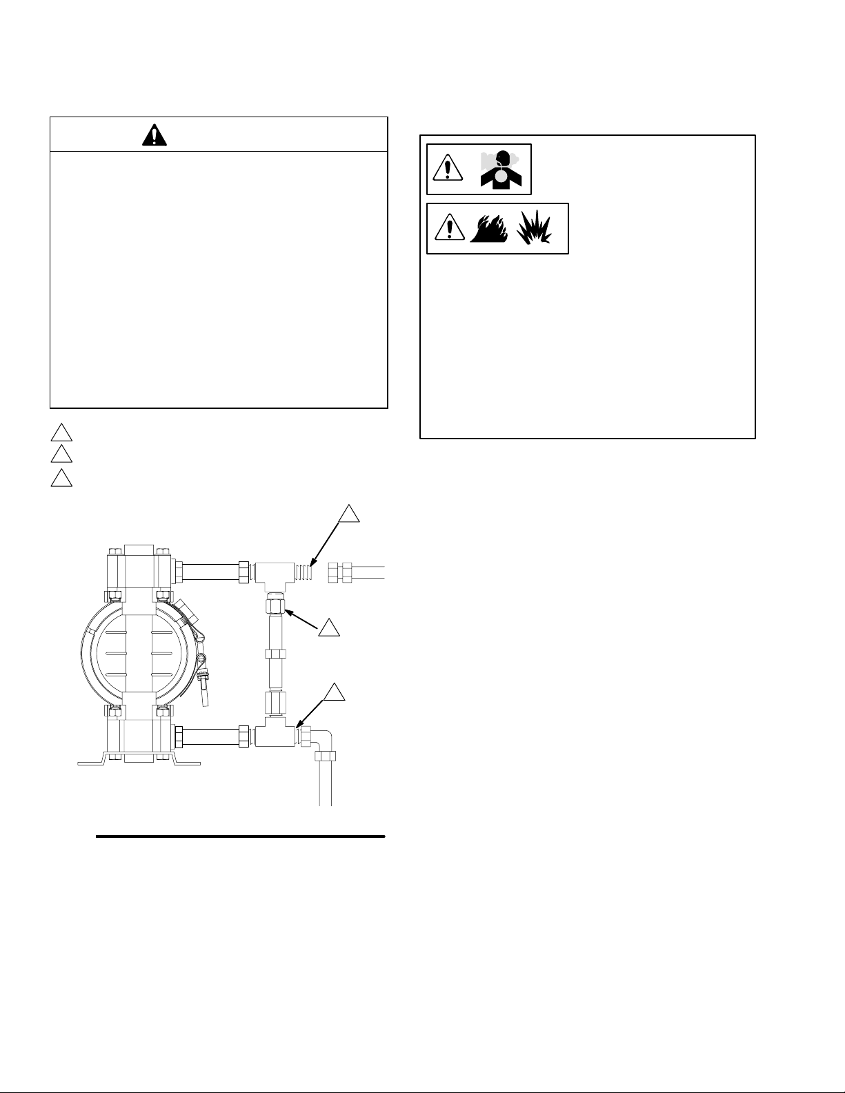
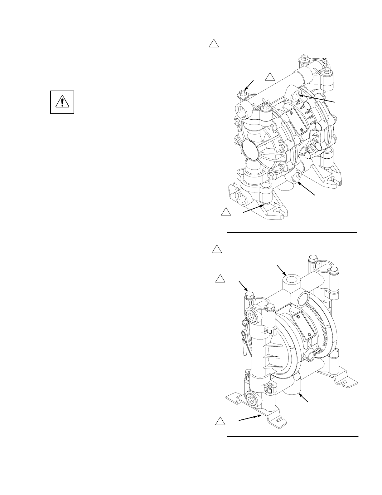
Fluid Pressure Relief Valve
CAUTION
Some systems may require installation of a pressure
relief valve at the pump outlet to prevent overpressurization and rupture of the pump or hose.
See Fig. 1.
Thermal expansion of fluid in the outlet line can
cause overpressurization. This can occur when using
long fluid lines exposed to sunlight or ambient heat,
or when pumping from a cool to a warm area (for
example, from an underground tank).
Overpressurization can also occur if the Husky pump
is being used to feed fluid to a piston pump, and the
intake valve of the piston pump does not close,
causing fluid to back up in the outlet line.
1
Install valve between fluid inlet and outlet ports.
2
Connect fluid inlet line here.
3
Connect fluid outlet line here.
3
Air Exhaust Ventilation
Read Toxic Fluid Hazard on
page 3.
Read Fire and Explosion
Hazard on page 3.
Be sure the system is properly ventilated for your
type of installation. You must vent the exhaust to a
safe place, away from people, animals, food handling areas, and all sources of ignition when pumping
flammable or hazardous fluids.
Diaphragm failure will cause the fluid being pumped
to exhaust with the air. Place an appropriate container at the end of the air exhaust line to catch the
fluid. See Fig. 2 .
The air exhaust port is 3/8 npt(f). Do not restrict the air
exhaust port. Excessive exhaust restriction can cause
erratic pump operation.
Fig. 1
See Venting Exhaust Air in Fig. 2. Exhaust to a
remote location as follows:
1
2
9073A
1. Remove the muffler (W) from the pump air exhaust
port.
2. Install an electrically conductive air exhaust hose
(X) and connect the muffler to the other end of the
hose. The minimum size for the air exhaust hose
is 3/8 in. (10 mm) ID. If a hose longer than 15 ft
(4.57 m) is required, use a larger diameter hose.
Avoid sharp bends or kinks in the hose.
3. Place a container (Z) at the end of the air exhaust
line to catch fluid in case a diaphragm ruptures.
See Fig. 2.
6 308981
Page 7
Installation
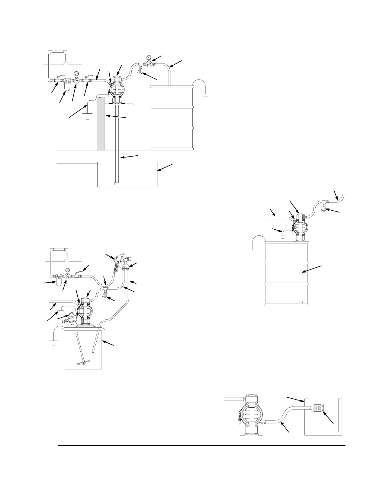
ABOVE-GROUND TRANSFER INSTALLATION
A
D
H
N
L
KEY
A Pump
C Electrically conductive air supply line
D Air line quick disconnect
H Fluid drain valve (required)
K Electrically conductive fluid supply hose
L Fluid suction line
Y Ground wire (required; see page 8
P
KEY
A Pump
C Electrically conductive air line to pump
T
E Gun air line shutoff valve
F Air line filter
K
H
U
G Gun air regulator
H Fluid drain valve (required)
K Electrically conductive fluid supply hose
P Circulating valve
R Electrically conductive air line to gun
S Air spray gun
T Electrically conductive fluid return line
U 5-gallon pail
V Agitator
Y Ground wire (required; see page 8
for installation instructions)
E
F
B
G
Y
AIR SPRAY INSTALLATION
E
F
D
G
C
V
Y
A
C
S
R
J
K
9074A
M
55-GALLON BUNG PUMP INSTALLATION
for installation instructions)
KEY
A Pump
B Bleed-type master air valve
(required for pump)
C Electrically conductive
air supply line
D Air line quick disconnect
E Master air valve (for accessories)
F Air line filter
G Pump air regulator
H Fluid drain valve (required)
J Fluid regulator (optional)
K Electrically conductive
fluid supply hose
L Fluid suction line
M Underground storage tank
N Wall mounting bracket
Y Ground wire (required; see page 8
for installation instructions)
A
C
D
Y
K
H
L
9075A
Fig. 2
9076A
KEY
W Muffler
X Electrically Conductive Air Exhaust Hose
Z Container for Remote Air Exhaust
All wetted and non-wetted pump parts must be
compatible with the fluid being pumped.
VENTING EXHAUST AIR
Z
X
W
04054
7308981
Page 8
Installation
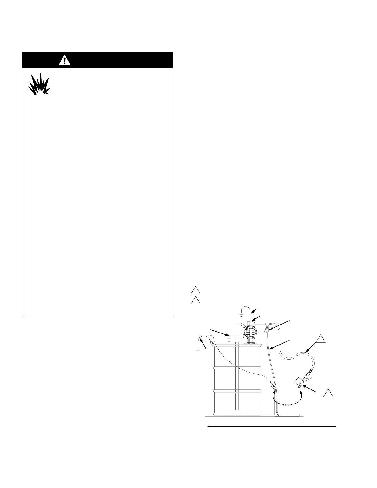
Grounding
WARNING
FIRE AND EXPLOSION HAZARD
This pump must be grounded. Before
operating the pump, ground the system
as explained below. Also read the sec-
tion Fire and Explosion Hazard on page 3.
The acetal Husky 515 pump contains stainless
steel fibers, which makes the wetted parts conductive. Attaching the ground wire to the grounding
screw (106) grounds the wetted parts. See
grounding screw on page 25.
The metal Husky 716 pumps have a grounding
strip connecting the vee clamps (109). Attach a
ground wire to the grounding strip with the screw,
lockwasher, and nut as shown in the Grounding
Detail on page 27.
The polypropylene and PVDF Husky 515 pumps
are not conductive.
When pumping conductive flammable fluids, al-
ways ground the entire fluid system by making
sure the fluid system has an electrical path to a
true earth ground (see Fig. 3). Never use a polypropylene or PVDF pump with non-conductive
flammable fluids as specified by your local fire
protection code.
US Code (NFPA 77 Static Electricity) recommends
a conductivity greater than 50 x 10
ter (mhos/meter) over your operating temperature
range to reduce the hazard of fire. Consult your
fluid supplier to determine the conductivity or
resistivity of your fluid. The resistivity must be less
than 2 x 10¹² ohm-centimeters.
To reduce the risk of static sparking, ground the pump
and all other equipment used or located in the pumping
area. Check your local electrical code for detailed
grounding instructions for your area and type of equipment.
–12
Siemans/me-
Ground all of this equipment:
Pump: The metal pump has a grounding strip in
front of the center housing. The acetal pump has a
grounding screw on the top manifold. Connect the
non-clamp end of the ground wire to the grounding
strip or grounding screw, and connect the clamp
end of the ground wire to a true earth ground. To
order a ground wire and clamp, order Part No.
222011.
Air and fluid hoses: Use only electrically conductive
hoses.
Air compressor: Follow the manufacturer’s recom-
mendations.
Solvent pails used when flushing: Follow the local
code. Use only grounded metal pails, which are
conductive. Do not place the pail on a non-conductive surface, such as paper or cardboard, which
interrupts the grounding continuity.
Fluid supply container: Follow the local code.
KEY
A Pump
H Fluid drain valve (required)
S Dispense valve
T Fluid drain line
Y Fluid section grounding via grounding strip or grounding
screw (required for metal and acetal pumps)
Z Container ground wire (required)
1
Hose must be conductive.
2
Dispense valve nozzle must be in contact with container.
Y
Z
GROUNDING A PUMP
Y
A
H
T
1
NOTE: When pumping conductive flammable fluids
with a polypropylene or PVDF pump, always ground
the fluid system. See the WARNING above. Fig. 3
shows a recommended method of grounding flammable fluid containers during filling.
8 308981
Fig. 3
2
S
9079A
Page 9
Installation
Changing the Orientation of the Fluid Inlet
and Outlet Ports (Husky 515)
You can change the orientation of the fluid inlet and
outlet ports by repositioning the manifolds. For Husky
515, see Fig. 4. For Husky 716, see Fig. 5.
1.
2. Remove the four manifold nuts (109) or bolts
(105).
3. Turn the manifold to the desired position, reinstall
the nuts or bolts, and torque to 80 to 90 in-lb
(9 to 10 Nm). See Torque Sequence, page 29.
NOTE: Make sure all manifold o-rings are positioned correctly before you fasten the manifold.
Manifold o-rings (139) are shown in Fig. 7 and Fig.
8.
NOTE: Pumps with duckbill check valves are shipped
with the inlet manifold on top and the outlet manifold
on the bottom. See page 14 for details.
Relieve the pressure. See Pressure Relief Procedure on page 10.
1
Torque to 80 to 90 in-lb (9 to 10 Nm). See
Torque Sequence, page 29.
1
109
1 109
Fig. 4
outlet
inlet
9065A
1
Torque to 80 to 90 in-lb (9 to 10 Nm). See
Torque Sequence, page 29.
outlet
1
105
1
105
Fig. 5
inlet
9071A
9308981
Page 10
Operation
Pressure Relief Procedure
WARNING
PRESSURIZED EQUIPMENT HAZARD
The equipment stays pressurized until pressure is
manually relieved. To reduce the risk of serious
injury from pressurized fluid, accidental spray, or
splashing fluid, follow this procedure whenever you
Are instructed to relieve pressure
Stop pumping
Check, clean, or service any system equipment
Install or clean fluid nozzles
1. Shut off the air to the pump.
2. Open the dispensing valve, if used.
3. Open the fluid drain valve to relieve all fluid pressure, and have a container ready to catch the
drainage.
Flush Pump Before First Use
The pump was tested with water. Prior to first use,
flush the pump thoroughly with a compatible solvent.
Reactor feed pumps, part numbers 246484, 246485,
and 257447, were tested with lightweight oil, which is
left in the fluid passages. To avoid contaminating your
fluid with oil, flush the pump with a compatible solvent
before using the equipment. Follow the steps under
Starting and Adjusting Pump.
Starting and Adjusting Pump
1.
Read Toxic Fluid Hazard
on page 3.
5. Place the suction tube (if used) in the fluid to be
pumped.
NOTE: If the inlet fluid pressure to the pump is more
than 25% of the outlet working pressure, the ball check
valves will not close fast enough, resulting in inefficient
pump operation.
6. Place the end of the fluid hose (K) into an appropriate container.
7. Close the fluid drain valve (H).
8. With the pump air regulator (G) closed, open all
bleed-type master air valves (B, E).
9. If the fluid hose has a dispensing device, hold it
open while continuing with the following step.
Slowly open the air regulator (G) until the pump
starts to cycle. Allow the pump to cycle slowly until
all air is pushed out of the lines and the pump is
primed.
If you are flushing, run the pump long enough to
thoroughly clean the pump and hoses. Close the
air regulator. Remove the suction tube from the
solvent and place it in the fluid to be pumped.
Operation of Remote Piloted Pumps
1. Fig. 2 and Parts Drawings. Follow preceding steps
1 through 8 of Starting and Adjusting Pump.
2. Open air regulator (G).
WARNING
The pump may cycle once before the external signal is applied. Injury is possible. If pump cycles,
wait until end before proceeding.
2.
3.
4. Check all fittings to be sure they are tight. Use a
compatible liquid thread sealant on all male
threads. Tighten the fluid inlet and outlet fittings
snugly. Do not overtighten the fittings into the
pump.
10 308981
If lifting the pump, follow the Pressure Relief Procedure above.
Be sure the pump is
properly grounded.
Read Fire and
Explosion Hazard
on page 3.
3. Pump will operate when air pressure is alternately
applied to push type connectors (16).
NOTE: Leaving air pressure applied to the air motor for
extended periods when the pump is not running may
shorten the diaphragm life. Using a 3–way solenoid
valve to automatically relieve the pressure on the air
motor when the metering cycle is complete prevents
this from occurring.
Pump Shutdown
At the end of the work shift, relieve
the pressure as described in Pressure Relief Procedure at left.
Page 11
Maintenance
Lubrication
The air valve is lubricated at the factory to operate
without additional lubrication. If you want to provide
additional lubrication, remove the hose from the pump
air inlet and add two drops of machine oil to the air
inlet every 500 hours of operation or every month.
CAUTION
Do not over-lubricate the pump. Oil is exhausted
through the muffler, which could contaminate your
fluid supply or other equipment. Excessive lubrication
can also cause the pump to malfunction.
Flushing and Storage
Flush the pump to prevent the fluid you are pumping
from drying or freezing in the pump and damaging it.
Use a compatible solvent.
Always flush the pump and relieve the pressure
before you store it for any length of time.
Read Pressure Relief Procedure
on page 10.
Tightening Threaded Connections
Before each use, check all hoses for wear or damage
and replace as necessary. Check to be sure all
threaded connections are tight and leak-free.
Check fasteners. Tighten or retorque as necessary.
Although pump use varies, a general guideline is to
retorque fasteners every two months. See Torque
Sequence, page 29.
Preventive Maintenance Schedule
Establish a preventive maintenance schedule, based
on the pump’s service history. This is especially important for prevention of spills or leakage due to diaphragm failure.
11308981
Page 12

Troubleshooting
Read Pressure Relief Procedure on page 10, and relieve the pressure before you check or service
the equipment. Check all possible problems and causes before disassembling the pump.
PROBLEM CAUSE SOLUTION
Pump will not cycle, or cycles once
and stops.
Pump cycles at stall or fails to hold
pressure at stall.
Pump operates erratically. Clogged suction line. Inspect; clear.
Air bubbles in fluid. Suction line is loose. Tighten.
Fluid in exhaust air. Diaphragm ruptured. Replace.
Pump exhausts air from clamps
(metal pumps).
Pump leaks fluid from check valves. Worn or damaged check valve
Air valve is stuck or dirty. Use filtered air.
Leaky check valves or o-rings. Replace.
Worn check balls or duckbill valves
or guides.
Check ball wedged in guide. Repair or replace.
Worn diaphragm shaft seals. Replace.
Sticky or leaking check valve balls. Clean or replace.
Diaphragm ruptured. Replace.
Diaphragm ruptured. Replace.
Loose manifolds or damaged man-
ifold o-rings.
Loose fluid side diaphragm plates. Tighten.
Loose fluid side diaphragm plates. Tighten.
Worn diaphragm shaft seals. Replace.
Loose clamps. Tighten clamp nuts.
Air valve o-ring is damaged. Inspect; replace.
o-rings.
Replace.
Tighten manifold bolts or nuts; replace o-rings.
Inspect; replace.
12 308981
Page 13

Service
Air Valve (Husky 515 and Husky 716 Pumps)
NOTE: Air Valve Repair Kit 241657 is available. Parts included in the kit are marked with a dagger () in Fig. 6 and
in the Parts Drawings and Lists. A tube of general purpose grease 111920 is supplied in the kit. Service the air
valve as follows. See Fig. 6.
1. Relieve the pressure. See
Pressure Relief Procedure on
page 10.
2. Remove the cover (10) and the o-ring (4).
3. Remove the carriage plungers (7), carriages (8),
carriage pins (9), and valve plate (14) from the
center housing (11).
4. Clean all the parts, and inspect them for wear or
damage.
NOTE: If you are installing the new Air Valve
Repair Kit 241657, use all the parts in the kit.
5. Grease the lapped surface of the valve plate (14),
and install the valve plate with the lapped surface
facing up.
6. Grease the bores of the center housing (11), install
the u-cup packings (2) on the carriage plungers
(7), and slide the carriage plungers into the carriage plunger bores. See the following important
installation notes:
NOTES:
When you install each u-cup packing (2) on each
carriage plunger (7), make sure the lips of the
u-cup packing face toward the clip end (the
smaller end) of the carriage plunger.
When you slide the carriage plungers (7) into the
bores, slide them in with the clip ends (the smaller
ends) facing toward the center of the center housing (11).
7. Grease the carriage pins (9), and slide the carriage
pins into the carriage pin bores.
8. Install the carriages (8). Make sure the carriages
engage the clip ends of the carriage plungers (7)
and carriage pins (9).
9. Grease the o-ring (4), and seat it in the groove
around the cover opening of the center housing (11).
10. Screw the cover (10) into the center housing, and
torque the cover to 80 to 100 in-lb (9.0 to 13.6 N-m).
NOTE: Center housing (11) is
shown separated from the air
covers, but it is not necessary to
remove the air covers for this
service. Leave the center housing
and air covers assembled for this
service.
Included in Air Valve Repair Kit 241657
Torque to 80 to 100 in-lb (9.0 to 13.6 N-m).
1
2
Apply grease.
Apply grease to lapped face.3
4
Apply grease to bores of center housing (11) before installing.
5
Seal lips face clip end (the smaller end) of carriage plunger (7).
Install with the clip ends (the smaller ends) facing toward center
6
of center housing (11).
Fig. 6
8
1
10
4
5
2
4
5
2
4 6
7
4 6
7
3
14
2
4
11
2
9
8
9
2
9069A
13308981
Page 14

Service
Ball or Duckbill Check Valves
NOTE: Fluid Section Repair Kit D05XXX is available.
See page 22 to order the correct kit for your pump.
Parts included in the kit are marked with a double
dagger () in Fig. 7 and Fig. 8 and in the Parts Drawings and Lists. General purpose grease 111920 and
Adhesive 113500 are supplied in the kit.
1. Relieve the pressure. See
Pressure Relief Procedure on
page 10.
2. Remove the top and bottom manifolds (102, 103).
3. Remove all parts shown with a dagger () in Fig. 7
and Fig. 8.
4. Clean all parts, and replace worn or damaged
parts.
5. Reassemble the pump.
NOTE: Torque the manifold nuts (109) or bolts
(105) to 80 to 90 in-lb (9 to 10 Nm). See Torque
Sequence, page 29.
Inlet and Outlet for Pumps with Duckbill
Check Valves
Pumps with duckbill check valves are shipped with the
inlet manifold on top and the outlet manifold on the
bottom. To make the inlet manifold on the bottom and
the outlet manifold on the top, rotate each of the four
duckbill assemblies vertically 180 as shown below.
139
201
202
9080A
14 308981
Page 15

Service
Husky 515
103
202
201
139
Husky 716
105
1
109
139
202
301
201
139
1
106
107
102
202
139
301
201
139
202
201
139
202
201
139
Fig. 7
139
202
301
201
139
Torque to 80 to 90 in-lb (9 to 10 N-m). See
1
Torque Sequence, page 29.
109
101
106
102
1
139
202
301
201
139
202
201
139
102
9067A
1
105
Fig. 8
Torque to 80 to 90 in-lb (9 to 10 N-m). See
1
Torque Sequence, page 29.
9081A
15308981
Page 16

Service
Diaphragms (Husky 515)
NOTE: Fluid Section Repair Kit D05XXX is available. See page 22 to order the correct kit for your pump. Parts
included in the kit are marked with a double dagger () in Fig. 9 and in the Parts Drawings and Lists. General
purpose grease 111920 and Adhesive 113500 are supplied in the kit. Service the diaphragms as follows. See Fig. 9.
Disassembly
Reassembly
1. Relieve the pressure. See
Pressure Relief Procedure on
page 10.
2. Remove manifolds (102 and 103) and fluid covers (101).
NOTE: Make sure all the check valve parts stay in
place. See Fig. 7 on page 15.
3. Remove one of the fluid-side diaphragm plates
(105) (whichever one comes loose first when you
use a wrench on the hex of each), and pull the
diaphragm shaft out of the center housing (11).
Overmolded Diaphragms: The air cover bolts
may make it difficult to remove the overmolded
diaphragms on the 515 pump. Use a flat surface
that fits within the bolt pattern to apply pressure on
one of the diaphragms to shift the diaphragm shaft
to one side. Apply pressure until the other diaphragm is separated from the air cover. Rotate the
separated diaphragm counterclockwise until the
diaphragm assembly comes free. Pull the second
diaphragm assembly and the diaphragm shaft (15)
out of the center housing. (11)
4. Use a wrench on the flats of the diaphragm shaft
(15) to remove the other fluid-side diaphragm plate
(105) from the diaphragm shaft.
1. Insert a diaphragm shaft u-cup (416) and a pilot
pin o-ring (1) into the bores of the center housing
(11).
NOTE: Make sure the lips of the u-cup face out of
the center housing.
2. Line up the holes in the gasket (12) with the holes
in the end of the center housing (11), and use six
screws (106) to fasten an air cover (113 or 114) to
the end of the center housing (11). Torque the
screws to 35 to 45 in-lb (4.0 to 5.1 N-m).
3. Position the exhaust cover (13) and o-ring (4) on
the center housing (11).
4. Repeat steps 1 and 2 for the other end of the
center housing and the remaining air cover.
5. Apply medium-strength (blue) Loctite or equivalent
to the threads of the fluid-side diaphragm plates
(105). Install on one end of the diaphragm shaft
(15) the following parts (see proper order in Fig. 9):
air-side diaphragm plate (6), backup diaphragm
(402, used only on models with PTFE diaphragms), diaphragm (401), and fluid-side diaphragm plate (105).
Overmolded Diaphragms: Use a wrench on the
flats of the diaphragm shaft (15) to remove the
second diaphragm.
5. Remove the screws (106), remove the left (114)
and right (113) air covers, and remove all old
gasket (12) material from the ends of the center
housing (11) and the surfaces of the air covers.
6. Remove the diaphragm shaft u-cups (416) and
pilot pin o-rings (1).
7. Inspect all parts for wear or damage, and replace
as necessary.
16 308981
NOTE: The words “AIR SIDE” on the diaphragm
(401), the backup diaphragm (402, used only on
models with PTFE diaphragms) and the flat side of
the air-side diaphragm plate (6) must face toward
the diaphragm shaft (15).
Overmolded Diaphragms: Assemble the air–side
plate (6) onto the diaphragm (401). The words AIR
SIDE on the air–side plate must face away from
the diaphragm. Apply medium–strength (blue)
thread locking adhesive to the threads of the
diaphragm assembly. Screw the assembly into the
diaphragm shaft (15) hand tight.
Page 17

6. Put grease on the diaphragm shaft (15), and
carefully (do not damage the shaft u-cups) run the
diaphragm shaft (15) through the center housing
(11) bore.
8. Install the muffler (3).
9. Make sure all the check valve parts are in place.
See Fig. 7 on page 15.
7. Repeat step 5 for the other end of the diaphragm
shaft (15), and torque the fluid-side diaphragm
plates (105) to 80 to 90 in-lb (9 to 10 N-m) at 100
rpm maximum.
Overmolded Diaphragms: The air cover bolts
may make it difficult to assemble the overmolded
diaphragms on the 515 pump. Two people are
needed. Use a flat surface that fits within the bolt
pattern to apply pressure on the diaphragm that
has already been assembled. Apply pressure until
the diaphragm shaft sticks out of the other end of
the center housing far enough to attach the second
diaphragm assembly. Screw the assembly into the
shaft (15) hand tight.
10. Reinstall the fluid covers (101) and manifolds (102
and 103), and torque the fluid cover and manifold
nuts (109) to 80 to 90 in-lb (9 to 10 N-m). See
Torque Sequence, page 29.
17308981
Page 18

Diaphragms (Husky 515)
Service
11
101
1
12
114
4
13
3
103
109
7
6
105
7
109
2
102
106
401
4
402
416
5
6
4
401
4
5
HD Overmolded Diaphragm
15
3
1
6
6
Fig. 9
109
Included in Fluid Section Repair Kit D05XXX
Install with lips facing out of center housing (11).
1
2
Torque to 35 to 45 in-lb (4.0 to 5.1 N-m).
Apply grease.
3
The words “AIR SIDE” on diaphragms (and on backup
4
7
diaphragms required on PTFE models) must face
toward diaphragm shaft (15).
Flat side of air-side diaphragm plate must face toward
5
diaphragm shaft (15).
Apply medium-strength (blue) Loctite or equivalent
6
to threads, and torque to 80 to 90 in-lb (9 to 10 N-m) at
100 rpm maximum.
Torque to 80 to 90 in-lb (9 to 10 N-m). See Torque Se-
7
quence, page 29.
18 308981
Page 19

Service
Diaphragms (Husky 716)
NOTE: Fluid Section Repair Kit D05XXX is available. See page 22 to order the correct kit for your pump. Parts
included in the kit are marked with a double dagger () in Fig. 10 and in the Parts Drawings and Lists. General
purpose grease 111920 and Adhesive 113500 are supplied in the kit. Service the diaphragms as follows. See
Fig. 10.
Disassembly
1. Relieve the pressure. See
Pressure Relief Procedure on
page 10.
2. Remove the manifolds (102) and fluid covers (101).
NOTE: Make sure all the check valve parts stay in
place. See Fig. 8 on page 15.
3. Remove the grounding strip from the vee clamps
(109), and remove the vee clamps.
4. Remove one of the fluid-side diaphragm plates
(133) (whichever one comes loose first when you
use a wrench on the hex of each), and pull the
diaphragm shaft out of the center housing (11).
Overmolded Diaphragms: Grip both diaphragms
securely around the outer edge and rotate counterclockwise. One diaphragm assembly will come
free and the other will remain attached to the
diaphragm shaft (15). Remove the freed diaphragm and the air side plate (6). Pull the other
diaphragm assembly and the diaphragm shaft (15)
out of the center housing (11).
5. Use a wrench on the flats of the diaphragm shaft
(15) to remove the other fluid-side diaphragm plate
(133) from the diaphragm shaft.
Reassembly
1. Insert a diaphragm shaft u-cup (416) and a pilot
pin o-ring (1) into the end of the diaphragm shaft
bore of the center housing (11).
NOTE: Make sure the lips of the u-cup face out of
the center housing.
2. Line up the holes in the gasket (12) with the holes
in the end of the center housing (11), and use six
screws (141) to fasten an air cover (136) to the
end of the center housing (11). Torque the screws
to 35 to 45 in-lb (4.0 to 5.1 N-m).
3. Position the exhaust cover (13) and o-ring (4) on
the center housing (11).
4. Repeat steps 1 and 2 for the other end of the
center housing and the remaining air cover.
5. Apply medium-strength (blue) Loctite or equivalent
to the threads of the screws (140). Install on one
end of the diaphragm shaft (15) the following parts
(see proper order in Fig. 10): air-side diaphragm
plate (6), backup diaphragm (402, used only on
models with PTFE diaphragms), diaphragm (401),
fluid-side diaphragm plate (133), o-ring (115), and
screw (140).
Overmolded Diaphragms: Use a wrench on the
flats of the diaphragm shaft (15) to remove the
second diaphragm from the diaphragm shaft.
6. Remove the screws (141) and air covers (136),
and remove all old gasket (12) material from the
ends of the center housing (11) and the surfaces of
the air covers.
7. Remove the diaphragm shaft u-cups (416) and
pilot pin o-rings (1).
8. Inspect all parts for wear or damage, and replace
as necessary.
NOTE: The words “AIR SIDE” on the diaphragm
(401), the backup diaphragm (402, used only on
models with PTFE diaphragms), and the flat side
of the air-side diaphragm plate (6) must face
toward the diaphragm shaft (15).
Overmolded Diaphragms: Assemble the air–side
plate (6) onto the diaphragm (401). The words AIR
SIDE on the air side plate must face away from the
diaphragm. Apply medium–strength (blue) thread
locking adhesive to the threads of the diaphragm
assembly. Screw the assembly into the diaphragm
shaft (15) hand tight.
19308981
Page 20

6. Put grease on the diaphragm shaft (15), and
carefully (do not damage the shaft u-cups) run the
diaphragm shaft (15) through the center housing
(11) bore.
7. Repeat step 5 for the other end of the diaphragm
shaft (15), and torque the diaphragm shaft screws
(140) to 80 to 90 in-lb (9 to 10 N-m) at 100 rpm
maximum.
Overmolded Diaphragms: Repeat Step 5 for the
other end of the diaphragm shaft (15).
8. Install the muffler (3).
When you install the vee clamps in step 10, orient the
center housing (11) so the air inlet is approximately
45 above horizontal and the muffler (3) is approximately horizontal.
9. Apply thin, even film of grease to inside of vee
clamp (109).
10. Position the fluid covers (101), install the vee
clamps (109) around the fluid and air covers,
install the grounding strip on the vee clamps, and
torque the vee clamp nuts to 80 to 90 in-lb (9 to 10
N-m). See Torque Sequence, page 29.
11. Make sure all the check valve parts are in place.
See Fig. 8 on page 15.
12. Install the manifolds (102), and torque the manifold
bolts (105) to 80 to 90 in-lb (9 to 10 N-m). See
Torque Sequence, page 29.
20 308981
Page 21

Diaphragms (Husky 716)
105
7
102
3
101
Service
11
416
1
4
13
141
2
3
12
136
109
4
402 6
5
102
105
7
Fig. 10
4
401
115
6
133
140
Included in Fluid Section Repair Kit D05XXX
Install with lips facing out of center housing (11).
1
2
Torque to 35 to 45 in-lb (4.0 to 5.1 N-m).
3
Apply grease.
The words “AIR SIDE” on diaphragms (and on backup diaphragms used
4
on PTFE models) must face toward diaphragm shaft (15).
Flat side of the air-side diaphragm plate must face
5
toward diaphragm shaft (15).
Apply medium-strength (blue) Loctite or equivalent
6
to threads, and torque to 80 to 90 in-lb (9 to 10 N-m) at
100 rpm maximum.
7
Torque to 80 to 90 in-lb (9 to 10 N-m). See
Torque Sequence, page 29.
4
401
3
15
1
416
5
6
6
HD Overmolded Diaphragm
9072A
21308981
Page 22

Husky 515 and Husky 716 Pump Matrix
Your Model No. is marked on the pump’s serial plate. To determine a pump Model No. from the following matrix,
select the six digits that describe the pump, working from left to right. The first digit is always D, designating Husky
diaphragm pumps. The remaining five digits define the air motor type and the materials of construction. For
example, a pump with a standard air motor, acetal fluid section, acetal seats, PTFE balls, and PTFE diaphragms is
Model D 5 1 2 1 1.
Column 1 Column 2 Column 3 Column 4 Column 5 Column 6
Diaphragm
Pump Air Motor Fluid Section Guides Balls Diaphragms
D (for all pumps) 4 (Husky 515/716;
remote-operated)
5 (Husky 515/716;
standard)
1 (acetal)
Husky 515, NPT
2 (polypropylene)
Husky 515, NPT
3 (aluminum)
Husky 716, NPT
4 (Stainless Steel)
Husky 716, NPT
5 (PVDF)
Husky 515, NPT
A (acetal)
Husky 515, BSPT
B (polypropylene)
Husky 515, BSPT
C (aluminum)
Husky 716, BSPT
D (stainless steel)
Husky 716, BSPT
E (PVDF)
Husky 515, BSPT
2 (acetal) 1 (PTFE) 1 (PTFE)
3 (316 sst) 3 (316 sst)
9 (polypropylene) 5 (TPE) 5 (TPE)
A (PVDF) 6 (Santoprene) 6 (Santoprene)
D (duckbill) 7 (buna-N) 7 (buna-N)
8 (fluoroelastomer) 8 (fluoroelastomer)
Note: The following models have ports that open downward. See page 23.
Husky 515: 241564, 241565, and 241484 Husky 716: 243305, 243306, 243307, 246485
Note: The following models have Heavy Duty Overmolded PTFE/EPDM Diaphragms. See page 23.
Husky 515: 24N093–24N098 Husky 716: 24N257–24N262
Husky 515 and Husky 716 Repair Kits
NOTE: Order Repair Kits separately.
To order the Air Valve Repair Kit, order Part No. 241657.
To order the Fluid Section Repair Kit, order Part No. D05 _ _ _ . For the last three digits, use the last three digits of
your pump Model No.
The guides in Part No. D_ _3_ _ pumps are powdered 316 stainless steel. Machined 316 stainless steel guides are
available separately in a kit, Part No. 24F846.
Part No. 24N320: Husky 515/716 HD Overmolded PTFE/EPDM Diaphragm Repair Kit
Part No. 24N321: Husky 515/716 HD overmolded PTFE/EPDM Diaphragm Repair Kit,
with new air side diaphragm plates.
22 308981
Page 23

Additional Husky 515 and Husky 716 Pumps
Model 241564, 515 pump
Same as the D51211 pump, but with an open
downward port.
Model 241565, 515 pump
Same as the D52911 pump, but with an open
downward port.
Model 248171, 515 pump
Same as the D51277 pump, except with split
inlets/outlets.
Model 248172, 515 pump
Same as the D51255 pump, except with split
inlets/outlets.
Model 248173, 515 pump
Same as the D52977 pump, except with split
inlets/outlets.
Model 248174, 515 pump
Same as the D52955 pump, except with split
inlets/outlets.
Model 246484, 515 pump
Same as the D51331 pump, but with an open
downward port. Use inlet manifold 241558.
Model 24G745, 515 pump
Same as the D5B981 pump, but with BSPP threads.
Model 246485, 716 pump
Same as the D53331 pump, but with an open
downward port. Use inlet manifold 190246.
Model 243305, 716 pump
Same as the D53266 pump, but with an open
downward port. Use inlet manifold 190246.
Model 243306, 716 pump
Same as the D53277 pump, but with an open
downward port. Use inlet manifold 190246.
Pumps with Overmolded Diaphragms
Model 24N093, 515 pump
Same as the D5291_ pump, but with overmolded
diaphragm parts shown in table.
Model 24N094, 515 pump
Same as the D5B91_ pump, but with overmolded
diaphragm parts shown in table.
Model 24N095, 515 pump
Same as the D55A1_ pump, but with overmolded
diaphragm parts shown in table.
Model 24N096, 515 pump
Same as the D5121_ pump, but with overmolded
diaphragm parts shown in table.
Model 24N097, 515 pump
Same as the D5133_ pump, but with overmolded
diaphragm parts shown in table.
Model 24N098, 515 pump
Same as the D5A21_ pump, but with overmolded
diaphragm parts shown in table.
Model 24N257, 716 pump
Same as the D5321_ pump, but with overmolded
diaphragm parts shown in table.
Model 24N258, 716 pump
Same as the D5331_ pump, but with overmolded
diaphragm parts shown in table.
Model 24N259, 716 pump
Same as the D5333_ pump, but with overmolded
diaphragm parts shown in table.
Model 24N260, 716 pump
Same as the D5421_ pump, but with overmolded
diaphragm parts shown in table.
Model 24N261, 716 pump
Same as the D5431_ pump, but with overmolded
diaphragm parts shown in table.
Model 24N262, 716 pump
Same as the D5433_ pump, but with overmolded
diaphragm parts shown in table.
Model 243307, 716 pump
Same as the D53211 pump, but with an open
downward port. Use inlet manifold 190246.
Model 257447, 716 pump
Same as the D54311 pump, but tested for use with
moisture–sensitive materials.
Model 24B674, 716 pump
Same as the D54311 pump
Ref. Part Description Qty.
6 16M001 PLATE, air side 2
115 ––––– not used 0
133 ––––– not used 0
140 ––––– not used 0
401 16H679 DIAPHRAGM, HD, overmolded,
PTFE/EPDM, with setscrew
402 ––––– not used 0
2
23308981
Page 24

Husky 515 and Husky 716 Common Parts
See the Pump Matrix on page 22 for an explanation of the Matrix Column and the Digit.
Air Motor Parts List (Matrix Column 2)
Ref.
Digit
No. Part No. Description Qty
5
1 114866 PACKING, o-ring 2
2 108808 PACKING, u-cup 2
3 112933 MUFFLER 1
4 162942 PACKING, o-ring 2
6 195025 PLATE, diaphragm, air
side
7 15Y825 PLUNGER, carriage 2
8 192595 CARRIAGE 2
9 192596 PIN, carriage 2
10 192597 COVER, valve chamber 1
11 192602 HOUSING, center 1
11* 194380 HOUSING, center 1
12 192765 GASKET 2
13 194247 COVER, exhaust 1
14 194269 PLATE, valve 1
15 192601 SHAFT, diaphragm 1
16* 115671 CONNECTOR, male 2
D 201 192138 SPACER 4
202 192137 VALVE, duckbill 4
Ball Parts List (Matrix Column 5)
Ref.
Digit
No. Part No. Description Qty
1 301 108639 BALL; PTFE 4
3 301 103462 BALL; sst 4
2
5 301 112945 BALL; TPE 4
6 301 112946 BALL; Santoprene 4
7 301 108944 BALL; buna-N 4
8 301 112959 BALL; fluoroelastomer 4
Diaphragm Parts List (Matrix Column 6)
Ref.
Digit
No. Part No. Description Qty
1
416 108808 PACKING, u-cup 2
401 108839 DIAPHRAGM; PTFE 2
402 183542 DIAPHRAGM, backup;
polyurethane
5
416 108808 PACKING, u-cup 2
401 189537 DIAPHRAGM; TPE 2
2
Guide Parts List (Matrix Column 4)
Ref.
Digit
No. Part No. Description Qty
2 201 186691 GUIDE; acetal 4
202 186692 STOP; acetal 4
3 201 187242 GUIDE; sst 4
202 187243 STOP; sst 4
9 201 186776 GUIDE; polypropylene 4
202 186777 STOP; polypropylene 4
A 201 192665 GUIDE; PVDF 4
202 192668 STOP; PVDF 4
6
416 108808 PACKING, u-cup 2
401 189536 DIAPHRAGM;
Santoprene
7
416 108808 PACKING, u-cup 2
401 190148 DIAPHRAGM; buna-N 2
8
416 108808 PACKING, u-cup 2
401 190149 DIAPHRAGM; fluoroelas-
tomer
2
2
Included in Air Valve Repair Kit 241657
Included in Fluid Section Repair Kit D05XXX
* These parts are unique to the remote operated air
motor.
24 308981
Page 25

Husky 515 Parts Drawing
Included in Air Valve Repair Kit 241657
202
201
139
103
101
115
109
111
139
202
301
201
139
105
106
grounding screw
(acetal pump only)
114
6
106
402
401
Included in Fluid Section Repair Kit D05XXX
* These parts are unique to the remote oper-
ated air motor.
12
10
202
201
139
104
102
109
139
202
301
201
139
117
109
16
416
9
4
17
15
1
11
14
113
8
7
2
101
116
4
13
3
9064B
25308981
Page 26

Husky 515 Fluid Section Parts List
See the Pump Matrix on page 22 for an explanation of the Matrix Column and the Digit.
See page 24 for Air Motor Parts List (Matrix Column 2)
Husky 515 Fluid Section Parts List (Matrix Column 3)
Acetal Pumps
Digit: 1 (NPT)
Digit: A (BSPT)
Ref.
Part No. Description Qty Part No. Description Qty Part No. Description Qty
No.
101 192559 COVER, fluid; acetal 2 192558 COVER, fluid;
102 192571 MANIFOLD, inlet;
acetal; NPT
102 192576 MANIFOLD, inlet;
acetal; BSPT
102* 241558 MANIFOLD, inlet;
open downspout,
acetal; NPT
102 124847 MANIFOLD, inlet;
103 192562 MANIFOLD, outlet;
acetal; NPT
103 192567 MANIFOLD, outlet;
acetal; BSPT
103 124848 MANIFOLD, outlet;
104 194362 PLUG; acetal;
3/4 NPT
104 194368 PLUG; acetal;
3/4 BSPT
105 187711 PLATE, diaphragm,
fluid; acetal
106 114882 SCREW, torx 13 114882 SCREW, torx 12 114882 SCREW, torx 12
109 114850 NUT, hex, large flng 24 114850 NUT, hex, large flng 24 114850 NUT, hex, large flng 24
111 187732 LABEL, warning 1 187732 LABEL, warning 1 187732 LABEL, warning 1
113 192599 COVER, air, right 1 192599 COVER, air, right 1 192599 COVER, air, right 1
114 192600 COVER, air, left 1 192600 COVER, air, left 1 192600 COVER, air, left 1
115 194352 LABEL, identification 2 194352 LABEL, identification 2 194352 LABEL, identification 2
116 290045 PLATE, designation 1 290045 PLATE, designation 1 290045 PLATE, designation 1
117 194359 PLUG; acetal;
1/2 NPT
117 194365 PLUG, acetal;
1/2 BSPT
119 111183 RIVET (for plate 116) 2 111183 RIVET (for plate 116) 2 111183 RIVET (for plate 116) 2
1 192570 MANIFOLD, inlet;
1 192575 MANIFOLD, inlet;
1 241557 MANIFOLD, inlet;
1 192561 MANIFOLD, outlet;
1 192566 MANIFOLD, outlet;
2 194361 PLUG; polypropy-
2 194367 PLUG; polypropy-
2 187712 PLATE, diaphragm,
2 194358 PLUG; polypropy-
2 194364 PLUG; polypropy-
Polypropylene Pumps
Digit: 2 (NPT)
Digit: B (BSPT)
polypropylene
polypropylene; NPT
polypropylene; BSPT
open downspout,
polypropylene; NPT
polypropylene; BSPP
polypropylene; NPT
polypropylene; BSPT
polypropylene; BSPP
lene; 3/4 NPT
lene; 3/4 BSPT
fluid; polypropylene
lene; 1/2 NPT
lene; 1/2 BSPT
PVDF Pumps
Digit: 5 (NPT)
Digit: E (BSPT)
2 192560 COVER, fluid; PVDF 2
1 192572 MANIFOLD, inlet;
PVDF; NPT
1 192577 MANIFOLD, inlet;
PVDF; BSPT
1 Not applicable to
PVDF pumps
1
1 192563 MANIFOLD, outlet;
PVDF; NPT
1 192568 MANIFOLD, outlet;
PVDF; BSPT
1
2 194363 PLUG; PVDF;
3/4 NPT
2 194369 PLUG; PVDF;
3/4 BSPT
2 192679 PLATE, diaphragm,
fluid; PVDF
2 194360 PLUG; PVDF;
1/2 NPT
2 194366 PLUG; PVDF;
1/2 BSPT
1
1
1
1
2
2
2
2
2
139114849 PACKING, o-ring;
encapsulated
8 114849 PACKING, o-ring;
encapsulated
8 114849 PACKING, o-ring;
encapsulated
* Inlet manifolds with downspouts are used on pump models 241564, 241565, and 246484 only.
26 308981
8
Page 27

Husky 716 Parts Drawing
Included in Air Valve Repair Kit 241657
Included in Fluid Section Repair Kit D05XXX
* These parts are unique to the remote operated air
motor.
105
107
102
103
10
4
14
9
8
7
2
106
106
112
139
202
301
201
139
101
117
139
202
301
201
202
201
139
202
201
139
109
140
136
401
133
115
16
12
402
141
17
11
1
416
134
4
13
3
15
416
6
Grounding Detail
112
102
105
139
123
122
121
110
108
9070A
27308981
Page 28

Husky 716 Fluid Section Parts List
See the Pump Matrix on page 22 for an explanation of the Matrix Column and the Digit.
See page 24 for Air Motor Parts List (Matrix Column 2)
Husky 716 Fluid Section Parts List (Matrix Column 3)
Aluminum Pumps
Digit: 3 (NPT)
Digit: C (BSPT)
Ref.
No.
101 185622 COVER, fluid; aluminum 2 187241 COVER, fluid; sst 2
102* 185624 MANIFOLD; aluminum; NPT 2 187244 MANIFOLD; sst 2
102 192061 MANIFOLD; aluminum; BSPT 2 192060 MANIFOLD; sst; BSPT 2
102 190246 MANIFOLD; aluminum; NPT 2
103 189220 LABEL, warning 1 189220 LABEL, warning 1
105 112912 SCREW; 3/8–16; 2.25 in. (57.2 mm) 8 112912 SCREW; 3/8–16; 2.25 in. (57.2 mm) 8
106 112913 NUT, hex; 3/8–16; sst 8 112913 NUT, hex; 3/8–16; sst 8
107 112914 WASHER, flat; 3/8 in.; sst 4 112914 WASHER, flat; 3/8 in.; sst 4
108 186207 BASE, feet 2 186207 BASE, feet 2
109 189540 CLAMP, vee 2 189540 CLAMP, vee 2
110 112499 NUT, clamp; 1/4–28 2 112499 NUT, clamp; 1/4–28 2
111 191079 STRIP, grounding 1 191079 STRIP, grounding 1
112 102726 PLUG, steel; NPT 2 111384 PLUG; sst; NPT 2
112 113989 PLUG, steel; BSPT 2 113990 PLUG; sst; BSPT 2
112 24H344 PLUG, sst; BSPP with seal 2
115 110004 O-RING; PTFE 2 110004 O-RING; PTFE 2
117 186205 LABEL, warning 1
121 102790 SCREW; 10–24; 0.31 in. (8 mm) 1 102790 SCREW; 10–24; 0.31 in. (8 mm) 1
122 100718 LOCKWASHER; #10 1 100718 LOCKWASHER; #10 1
123 100179 NUT, hex; 10–24 1 100179 NUT, hex; 10–24 1
133 191837 PLATE, diaphragm, fluid side; sst 2 16M908 PLATE, diaphragm, fluid side; sst
134 290045 PLATE, designation 1 290045 PLATE, designation 1
136 194246 COVER air 2 194246 COVER air 2
139 110636 O-RING; PTFE 8 110636 O-RING; PTFE 8
140 113747 SCREW, flange; hex head 2 113747 SCREW, flange; hex head 2
141 114882 SCREW, machine, torx 12 114882 SCREW, machine, torx 12
142 11118 3 RIVET (for plate 134) 2 111183 RIVET (for plate 134) 2
Part No. Description Qty Part No. Description Qty
Stainless Steel (sst) Pumps
Digit: 4 (NPT)
Digit: D (BSPT)
machined
2
Included in Fluid Section Repair Kit D05XXX
*Pump model numbers 243305, 243306, 243307, and 246485 have one 190246 inlet manifold and one 185624
outlet manifold.
28 308981
Page 29

Torque Sequence
Always follow torque sequence when instructed to torque fasteners.
Husky 515
1. Left/Right Fluid Covers
Torque bolts to 80–90 in–lb (9–10 Nm)
1111
88
6
4
SIDE VIEW
2. Inlet Manifold
Torque bolts to 80–90 in–lb (9–10 Nm)
11
3
5
7
2
10
Husky 716
1. Left/Right Fluid Covers
Torque bolts to 80–90 in–lb (9–10 Nm)
2
FRONT VIEW
2. Inlet Manifold
Torque bolts to 80–90 in–lb (9–10 Nm)
5
1
3
9
BOTTOM VIEW
12
3. Outlet Manifold
Torque bolts to 80–90 in–lb (9–10 Nm)
13
15
TOP VIEW
16
14
4
4
BOTTOM VIEW
6
6
3. Outlet Manifold
Torque Bolts to 80–90 in–lb (9–10 Nm)
9
8
TOP VIEW
7
10
29308981
Page 30

Husky 515 Technical Data
Maximum fluid working pressure 100 psi (0.7 MPa, 7 bar). . . . . . . . . . . . . . . . . . . . . . . . . . . . . . . . . . . . . . . . . . .
Air pressure operating range 30 to 100 psi (0.2 to 0.7 MPa, 2.1 to 7 bar ). . . . . . . . . . . . . . . . . . . . . . . . . . . . . .
Operating Temperature Range*
Minimum (all pumps) 40F (4C). . . . . . . . . . . . . . . . . . . . . . . . . . . . . . . . . . . . . . . . . . . . . . . . . . . . . . . . . . . . . .
Maximum
Acetal: 180F (82 C). . . . . . . . . . . . . . . . . . . . . . . . . . . . . . . . . . . . . . . . . . . . . . . . . . . . . . . . . . . . . . . . . . . . . . .
Polypropylene: 150F (66C). . . . . . . . . . . . . . . . . . . . . . . . . . . . . . . . . . . . . . . . . . . . . . . . . . . . . . . . . . . . . . . .
Aluminum, stainless steel, PVDF: 225F (107C). . . . . . . . . . . . . . . . . . . . . . . . . . . . . . . . . . . . . . . . . . . . . .
Maximum air consumption 28 scfm (0.672 cubic meters/min.). . . . . . . . . . . . . . . . . . . . . . . . . . . . . . . . . . . . . . .
Maximum free flow delivery (1/2 in. ports) 15 gpm (57 l/min). . . . . . . . . . . . . . . . . . . . . . . . . . . . . . . . . . . . . . . . .
Maximum pump speed 400 cpm. . . . . . . . . . . . . . . . . . . . . . . . . . . . . . . . . . . . . . . . . . . . . . . . . . . . . . . . . . . . . . . . .
Gallons (Liters) per cycle 0.04 (0.15). . . . . . . . . . . . . . . . . . . . . . . . . . . . . . . . . . . . . . . . . . . . . . . . . . . . . . . . . . . . . .
Maximum suction lift (water w/buna balls) 15 ft (4.5 m) dry,. . . . . . . . . . . . . . . . . . . . . . . . . . . . . . . . . . . . . . . . . .
25 ft (7.6 m) wet
Maximum size pumpable solids 3/32 in. (2.5 mm). . . . . . . . . . . . . . . . . . . . . . . . . . . . . . . . . . . . . . . . . . . . . . . . . .
Sound power level (measured per ISO standard 9614–2)
At 70 psig (0.48 MPa, 4.8 bar) at 50 cycles per minute 77 dBa. . . . . . . . . . . . . . . . . . . . . . . . . . . . . . . . . . . .
At 100 psig (0.7 MPa, 7 bar) at maximum cycles per minute 95 dBa. . . . . . . . . . . . . . . . . . . . . . . . . . . . . . .
Sound pressure level (measured 1 meter from pump)
At 70 psig (0.48 MPa, 4.8 bar) at 50 cycles per minute 67 dBa. . . . . . . . . . . . . . . . . . . . . . . . . . . . . . . . . . . . .
At 100 psig (0.7 MPa, 7 bar) at maximum cycles per minute 85 dBa. . . . . . . . . . . . . . . . . . . . . . . . . . . . . . . .
Air inlet size 1/4 npt(f). . . . . . . . . . . . . . . . . . . . . . . . . . . . . . . . . . . . . . . . . . . . . . . . . . . . . . . . . . . . . . . . . . . . . . . . . .
Air exhaust port size 3/8 npt(f). . . . . . . . . . . . . . . . . . . . . . . . . . . . . . . . . . . . . . . . . . . . . . . . . . . . . . . . . . . . . . . . . . .
Fluid inlet size. 1/2 and 3/4 in. npt(f) or bspt(f). . . . . . . . . . . . . . . . . . . . . . . . . . . . . . . . . . . . . . . . . . . . . . . . . . . . . .
Fluid outlet size. 1/2 and 3/4 in. npt(f) or bspt(f). . . . . . . . . . . . . . . . . . . . . . . . . . . . . . . . . . . . . . . . . . . . . . . . . . . .
Wetted parts (in addition to ball, seat, and diaphragm materials, which vary by pump)
Polypropylene pumps polypropylene, PTFE. . . . . . . . . . . . . . . . . . . . . . . . . . . . . . . . . . . . . . . . . . . . . . . . . . . . . .
Acetal pumps groundable acetal, PTFE. . . . . . . . . . . . . . . . . . . . . . . . . . . . . . . . . . . . . . . . . . . . . . . . . . . . . . . . .
PVDF pumps PVDF, PTFE. . . . . . . . . . . . . . . . . . . . . . . . . . . . . . . . . . . . . . . . . . . . . . . . . . . . . . . . . . . . . . . . . . . .
Non-wetted external parts polypropylene, stainless steel, polyester and aluminum (labels),. . . . . . . . . . . . . . .
nickel-plated brass
Weight (approximate)
Polypropylene pumps 6.5 lb (2.9 kg). . . . . . . . . . . . . . . . . . . . . . . . . . . . . . . . . . . . . . . . . . . . . . . . . . . . . . . . . . . .
Acetal pumps 7.8 lb (3.5 kg). . . . . . . . . . . . . . . . . . . . . . . . . . . . . . . . . . . . . . . . . . . . . . . . . . . . . . . . . . . . . . . . . . .
PVDF pumps 8.5 lb (3.9 kg). . . . . . . . . . . . . . . . . . . . . . . . . . . . . . . . . . . . . . . . . . . . . . . . . . . . . . . . . . . . . . . . . . .
*These temperatures are based on mechanical stress only and may be altered significantly by pumping certain
chemicals. Consult engineering guides for chemical compatibilities and temperature limits, or contact your
Graco distributor.
Santoprene is a registered trademark of the Monsanto Company.
Loctite is a registered trademark of the Loctite Corporation.
30 308981
Page 31

Husky 515 Dimensions
* Pumps with duckbill
check valves are shipped
with the inlet manifold on
top and the outlet manifold
on the bottom. To make
the inlet manifold on the
bottom and the outlet
manifold on the top, rotate
each of the four duckbill
assemblies vertically 180
as shown below.
139
201
202
SIDE VIEW
1/4 npt(f)
Air Inlet
7.75 in.
(196.9 mm)
3.13 in.
(79.5 mm)
4.70 in.
(119 mm)
1/2 npt(f) or
bspt(f)
Fluid Inlet *
FRONT VIEW
5.01 in.
(127 mm)
6.12 in.
(155.4 mm)
3/4 npt(f) or
bspt(f)
Fluid Inlet *
Note: Bottom port open on
241564, 241565, and 246484 only.
1/2 npt(f) or bspt(f) Fluid Outlet *
8.56 in.
(217.4
mm)
1.38 in.
(35.1 mm)
9.94 in.
(252.5
mm)
10.63 in.
(270.0 mm)
3/4 npt(f) or
bspt(f)
Fluid Outlet *
3/4 npt (f)
or bspt(f)
Fluid Inlet *
4.30 in.
(109.2 mm)
6.25 in.
(158.8 mm)
4.30 in.
(109.2 mm)
PUMP MOUNTING HOLE PATTERN
Four 0.30 in.
(7.6 mm)
Diameter Slots
6.12 in.
(155.4 mm)
9077A
31308981
Page 32

Husky 716 Technical Data
Maximum fluid working pressure 100 psi (0.7 MPa, 7 bar). . . . . . . . . . . . . . . . . . . . . . . . . . . . . . . . . . . . . . . . . . .
Air pressure operating range 30 to 100 psi (0.2 to 0.7 MPa, 2.1 to 7 bar ). . . . . . . . . . . . . . . . . . . . . . . . . . . . . .
Operating Temperature Range*
Minimum (all pumps) 40F (4C). . . . . . . . . . . . . . . . . . . . . . . . . . . . . . . . . . . . . . . . . . . . . . . . . . . . . . . . . . . . . .
Maximum
Acetal: 180F (82 C). . . . . . . . . . . . . . . . . . . . . . . . . . . . . . . . . . . . . . . . . . . . . . . . . . . . . . . . . . . . . . . . . . . . . . .
Polypropylene: 150F (66C). . . . . . . . . . . . . . . . . . . . . . . . . . . . . . . . . . . . . . . . . . . . . . . . . . . . . . . . . . . . . . . .
Aluminum, stainless steel, PVDF: 225F (107C). . . . . . . . . . . . . . . . . . . . . . . . . . . . . . . . . . . . . . . . . . . . . .
Maximum air consumption 28 scfm (0.672 cubic meters/min.). . . . . . . . . . . . . . . . . . . . . . . . . . . . . . . . . . . . . . .
Maximum free flow delivery 16 gpm (61 l/min). . . . . . . . . . . . . . . . . . . . . . . . . . . . . . . . . . . . . . . . . . . . . . . . . . . . . .
Maximum pump speed 400 cpm. . . . . . . . . . . . . . . . . . . . . . . . . . . . . . . . . . . . . . . . . . . . . . . . . . . . . . . . . . . . . . . . .
Gallons (Liters) per cycle 0.04(0.15). . . . . . . . . . . . . . . . . . . . . . . . . . . . . . . . . . . . . . . . . . . . . . . . . . . . . . . . . . . . . .
Maximum suction lift (water w/buna balls) 15 ft (4.5 m) dry,. . . . . . . . . . . . . . . . . . . . . . . . . . . . . . . . . . . . . . . . . .
25 ft (7.6 m) wet
Maximum size pumpable solids 3/32 in. (2.5 mm). . . . . . . . . . . . . . . . . . . . . . . . . . . . . . . . . . . . . . . . . . . . . . . . . .
Sound power level (measured per ISO standard 9614–2)
At 70 psig (0.48 MPa, 4.8 bar) at 50 cycles per minute 77 dBa. . . . . . . . . . . . . . . . . . . . . . . . . . . . . . . . . . . .
At 100 psig (0.7 MPa, 7 bar) at maximum cycles per minute 95 dBa. . . . . . . . . . . . . . . . . . . . . . . . . . . . . . .
Sound pressure level (measured 1 meter from pump)
At 70 psig (0.48 MPa, 4.8 bar) at 50 cycles per minute 67 dBa. . . . . . . . . . . . . . . . . . . . . . . . . . . . . . . . . . . . .
At 100 psig (0.7 MPa, 7 bar) at maximum cycles per minute 85 dBa. . . . . . . . . . . . . . . . . . . . . . . . . . . . . . .
Air inlet size 1/4 npt(f). . . . . . . . . . . . . . . . . . . . . . . . . . . . . . . . . . . . . . . . . . . . . . . . . . . . . . . . . . . . . . . . . . . . . . . . . .
Air exhaust port size 3/8 npt(f). . . . . . . . . . . . . . . . . . . . . . . . . . . . . . . . . . . . . . . . . . . . . . . . . . . . . . . . . . . . . . . . . . .
Fluid inlet size. 3/4 npt(f), bspt(f), or bspp(f). . . . . . . . . . . . . . . . . . . . . . . . . . . . . . . . . . . . . . . . . . . . . . . . . . . . . . . .
Fluid outlet size. 3/4 npt(f), bspt(f), or bspp(f). . . . . . . . . . . . . . . . . . . . . . . . . . . . . . . . . . . . . . . . . . . . . . . . . . . . . .
Wetted parts (in addition to ball, seat, and diaphragm materials, which vary by pump)
Aluminum pumps aluminum, stainless steel, PTFE, zinc-plated steel. . . . . . . . . . . . . . . . . . . . . . . . . . . . . . .
Stainless steel pumps 316 stainless steel, PTFE. . . . . . . . . . . . . . . . . . . . . . . . . . . . . . . . . . . . . . . . . . . . . . . . .
Non-wetted external parts polypropylene, stainless steel, polyester (labels),. . . . . . . . . . . . . . . . . . . . . . . . . . . .
nickel-plated brass, epoxy-coated steel (feet)
Weight (approximate)
Aluminum pumps 8.5 lb (3.9 kg). . . . . . . . . . . . . . . . . . . . . . . . . . . . . . . . . . . . . . . . . . . . . . . . . . . . . . . . . . . . . . .
Stainless steel pumps 18 lb (8.2 kg). . . . . . . . . . . . . . . . . . . . . . . . . . . . . . . . . . . . . . . . . . . . . . . . . . . . . . . . . . . .
*These temperatures are based on mechanical stress only and may be altered significantly by pumping certain
chemicals. Consult engineering guides for chemical compatibilities and temperature limits, or contact your
Graco distributor.
Santoprene is a registered trademark of the Monsanto Company.
Loctite is a registered trademark of the Loctite Corporation.
32 308981
Page 33

* Pumps with duckbill
check valves are shipped
with the inlet manifold on
top and the outlet manifold
on the bottom. To make
the inlet manifold on the
bottom and the outlet
manifold on the top, rotate
each of the four duckbill
assemblies vertically 180
as shown below.
139
201
Husky 716 Dimensions
FRONT VIEW
1/4 npt(f)
Air Inlet
7.37 in.
(187.2 mm)
4.25 in.
(108.0 mm)
4.44 in.
(112.8 mm)
3/4 npt(f), bspt(f), or bspp(f)
Fluid Outlet *
10.43 in.
(264.9
mm)
7.80 in.
(198.1
mm)
9.18 in.
(233.2
mm)
202
3/4 npt(f)
or bspt(f)
Fluid Outlets *
SIDE VIEW
2.76 in.
(62.5 mm)
6.62 in.
(168.1 mm)
3/4 npt(f)
or bspt(f)
Fluid Inlets *
Note: Bottom port open on 243305,
243306, 243307, and 246485 only.
PUMP MOUNTING HOLE PATTERN
4.29 in.
(109.0 mm)
1.38 in.
(35.1 mm)
3/4 npt(f), bspt(f), or bspp(f)
Fluid Outlet *
Four 0.28 in.
(7.1 mm)
Diameter Slots
4.29 in.
(109.0 mm)
6.04 in.
(153.4 mm)
3/4 npt(f)
or bspt(f)
Fluid Inlets *
6.62 in.
(168.1 mm)
9078A
33308981
Page 34

Husky 515 and 716 Performance Charts
Fluid Outlet Pressure
Test Conditions: Pump tested in water with inlet submerged.
100
(0.7, 7)
A
80
(0.55, 5.5)
B
60
(0.41, 4.1)
40
(0.28, 2.8)
FLUID OUTLET PRESSURE––psi (MPa, bar)
20
(0.14, 1.4)
0
0246810121416
C
(7.6) (15.2) (22.7) (30.3) (37.9) (45.4) (53.0) (60.6)
Fluid Pressure Curves
A at 100 psi (0.7 MPa, 7 bar) air pressure
B at 70 psi (0.48 MPa, 4.8 bar) air pressure
C at 40 psi (0.28 MPa, 2.8 bar) air pressure
FLUID FLOW––gpm (lpm)
To find Fluid Outlet Pressure (psi/MPa/bar) at a
specific fluid flow (gpm/lpm) and operating air
pressure (psi/MPa/bar):
1. Locate fluid flow rate along bottom of chart.
2. Follow vertical line up to intersection with selected
fluid outlet pressure curve.
3. Follow left to scale to read fluid outlet pressure.
34 308981
Page 35

Husky 515 and 716 Performance Charts
Air Consumption
Test Conditions: Pump tested in water with inlet submerged.
30
(0.84)
A at 100 psi (0.7 MPa, 7 bar) air pressure
25
(0.70)
(0.56)
(0.42)
(0.28)
AIR CONSUMPTION––scfm (cubic meters/min)
(0.14)
B at 70 psi (0.48 MPa, 4.8 bar) air pressure
C at 40 psi (0.28 MPa, 2.8 bar) air pressure
20
15
10
5
0
0246810121416
Air Consumption Curves
(7.6) (15.2) (22.7) (30.3) (37.9) (45.4) (53.0) (60.6)
A
B
C
To find Pump Air Consumption (scfm or m/min) at a
specific fluid flow (gpm/lpm) and air pressure
(psi/MPa/bar):
1. Locate fluid flow rate along bottom of chart.
2. Read vertical line up to intersection with selected air
consumption curve.
3. Follow left to scale to read air consumption.
FLUID FLOW––gpm (lpm)
35308981
Page 36

Graco Warranties
Graco Standard Husky Pump Warranty
Graco warrants all equipment manufactured by Graco and bearing its name to be free from defects in material and workmanship on the
date of sale to the original purchaser for use. With the exception of any special, extended, or limited warranty published by Graco,
Graco will, for a period of five years from the date of sale, repair or replace any part of the equipment determined by Graco to be defective. This warranty applies only when the equipment is installed, operated and maintained in accordance with Graco’s written recommendations.
This warranty does not cover, and Graco shall not be liable for general wear and tear, or any malfunction, damage or wear caused by
faulty installation, misapplication, abrasion, corrosion, inadequate or improper maintenance, negligence, accident, tampering, or substitution of non-Graco component parts. Nor shall Graco be liable for malfunction, damage or wear caused by the incompatibility of
Graco equipment with structures, accessories, equipment or materials not supplied by Graco, or the improper design, manufacture,
installation, operation or maintenance of structures, accessories, equipment or materials not supplied by Graco.
This warranty is conditioned upon the prepaid return of the equipment claimed to be defective to an authorized Graco distributor for
verification of the claimed defect. If the claimed defect is verified, Graco will repair or replace free of charge any defective parts. The
equipment will be returned to the original purchaser transportation prepaid. If inspection of the equipment does not disclose any defect
in material or workmanship, repairs will be made at a reasonable charge, which charges may include the costs of parts, labor, and
transportation.
THIS WARRANTY IS EXCLUSIVE, AND IS IN LIEU OF ANY OTHER WARRANTIES, EXPRESS OR IMPLIED, INCLUDING BUT
NOT LIMITED TO WARRANTY OF MERCHANTABILITY OR WARRANTY OF FITNESS FOR A PARTICULAR PURPOSE.
Graco’s sole obligation and buyer’s sole remedy for any breach of warranty shall be as set forth above. The buyer agrees that no other
remedy (including, but not limited to, incidental or consequential damages for lost profits, lost sales, injury to person or property, or any
other incidental or consequential loss) shall be available. Any action for breach of warranty must be brought within six years of the date
of sale.
Graco makes no warranty, and disclaims all implied warranties of merchantability and fitness for a particular purpose in connection
with accessories, equipment, materials or components sold but not manufactured by Graco. These items sold, but not manufactured
by Graco (such as electric motors, switches, hose, etc.), are subject to the warranty, if any, of their manufacturer. Graco will provide
purchaser with reasonable assistance in making any claim for breach of these warranties.
In no event will Graco be liable for indirect, incidental, special or consequential damages resulting from Graco supplying equipment
hereunder, or the furnishing, performance, or use of any products or other goods sold hereto, whether due to a breach of contract,
breach of warranty, the negligence of Graco, or otherwise.
FOR GRACO CANADA CUSTOMERS
The parties acknowledge that they have required that the present document, as well as all documents, notices and legal proceedings
entered into, given or instituted pursuant hereto or relating directly or indirectly hereto, be drawn up in English. Les parties reconnaissent avoir convenu que la rédaction du présente document sera en Anglais, ainsi que tous documents, avis et procédures judiciaires
exécutés, donnés ou intentés à la suite de ou en rapport, directement ou indirectement, avec les procedures concernées.
Extended Product Warranty
Graco warrants all Husky 205, 307, 515, 716, 1040, 1590, 2150, and 3275 air valve center sections to be free from defects in material
and workmanship for a period of fifteen years from date installed in service by the original purchaser. Normal wear of items such as
packings or seals are not considered to be defects in material and workmanship.
Five years Graco will provide parts and labor.
Six to Fifteen years Graco will replace defective parts only.
Graco Information
For the latest information about Graco products, visit www.graco.com.
TO PLACE AN ORDER, contact your Graco distributor or call to identify the distributor closest to you:
Phone: 612–623–6921 or Toll Free: 1–800–328–0211 Fax: 612–378–3505
All written and visual data contained in this document reflects the latest product information available at the time of publication.
Graco reserves the right to make changes at any time without notice.
Original instructions. This manual contains English. MM 308981
For patent information, see www.graco.com/patents.
International Offices: Belgium, China, Japan, Korea
GRACO INC. AND SUBSIDIARIES
Copyright 2000, Graco Inc. All Graco manufacturing locations are registered to ISO 9001.
36 308981
Graco Headquarters: Minneapolis
P.O. BOX 1441 MINNEAPOLIS, MN 55440-1441 USA
www.graco.com
Revised June 2012
 Loading...