


Graco D5B, D55, 716, D53, D5A User Manual
...Instructions
Air–Operated
Diaphragm Pumps
308981ZAC
EN
For fluid transfer applications. For professional use only.
Only models marked with (*) are approved for use in European explosive atmosphere locations.
100 psi (0.7 MPa, 7 bar) Maximum Fluid Working Pressure 100 psi (0.7 MPa, 7 bar) Maximum Air Input Pressure
ACETAL, POLYPROPYLENE, AND PVDF
Huskyt 515
Model No. D 5 1 _ _ _ Acetal NPT Pumps* Model No. D 5 2 _ _ _ Polypropylene Pumps Model No. D 5 5 _ _ _ PVDF NPT Pumps Model No. D 5 A _ _ _ Acetal BSPT Pumps*
Model No. D 5 B _ _ _ Polypropylene BSPT Pumps Model No. D 5 E _ _ _ PVDF BSPT Pumps
For Additional Models, see Table of Contents
Husky 515 9065A
ALUMINUM AND STAINLESS STEEL*
Huskyt 716
Model No. D 5 3 _ _ _ Aluminum NPT Pumps Model No. D 5 4 _ _ _ Stainless Steel NPT Pumps Model No. D 5 C _ _ _ Aluminum BSPT Pumps Model No. D 5 D _ _ _ Stainless Steel BSPT Pumps For Additional Models, see Table of Contents
*These models are |
certified. |
Important Safety Instructions
Read all warnings and instructions in this manual. Save these instructions.
Refer to the Pump Matrix on page 22 to determine the model number of your pump.
9246A
Husky 716
Table of Contents
Safety Warnings . . . . . . . . . . . . . . . . . . . . . . . . . . . . . . . 2
Installation . . . . . . . . . . . . . . . . . . . . . . . . . . . . . . . . . . . . . 4
Operation . . . . . . . . . . . . . . . . . . . . . . . . . . . . . . . . . . . . 10
Maintenance . . . . . . . . . . . . . . . . . . . . . . . . . . . . . . . . . . 11
Troubleshooting . . . . . . . . . . . . . . . . . . . . . . . . . . . . . . . 12
Service . . . . . . . . . . . . . . . . . . . . . . . . . . . . . . . . . . . . . . 13
Husky 515 and Husky 716 Pump Matrix . . . . . . . . . . 22
Husky 515 and 715 Additional Pumps . . . . . . . . . . . . 23
Husky 515 and Husky 716 Repair Kits . . . . . . . . . . . . 22
Parts
Husky 515 and Husky 716 Common Parts . . . . . . 24
Husky 515 Parts Drawing . . . . . . . . . . . . . . . . . . . . 25
Husky 515 Fluid Section Parts List . . . . . . . . . . . . . 26
Husky 716 Parts Drawing . . . . . . . . . . . . . . . . . . . . 27
Husky 716 Fluid Section Parts List . . . . . . . . . . . . . 28
Torque Sequence . . . . . . . . . . . . . . . . . . . . . . . . . . . . . 29
Husky 515:
Technical Data . . . . . . . . . . . . . . . . . . . . . . . . . . . . . . 30
Dimensions . . . . . . . . . . . . . . . . . . . . . . . . . . . . . . . . . 31
Husky 716:
Technical Data . . . . . . . . . . . . . . . . . . . . . . . . . . . . . . 32
Dimensions . . . . . . . . . . . . . . . . . . . . . . . . . . . . . . . . . 33
Husky 515 and Husky 716 Performance Charts . . . 34
Graco Standard Warranty . . . . . . . . . . . . . . . . . . . . . . 36
Graco Information . . . . . . . . . . . . . . . . . . . . . . . . . . . . . 36
Symbols
Warning Symbol
 WARNING
This symbol alerts you to the possibility of serious injury or death if you do not follow the instructions.
Caution Symbol
 CAUTION
This symbol alerts you to the possibility of damage to or destruction of equipment if you do not follow the instructions.
 WARNING
EQUIPMENT MISUSE HAZARD
Equipment misuse can cause the equipment to rupture or malfunction and result in serious injury.
INSTRUCTIONS D This equipment is for professional use only.
DRead all instruction manuals, tags, and labels before operating the equipment.
DUse the equipment only for its intended purpose. If you are not sure, call your Graco distributor.
DDo not alter or modify this equipment. Use only genuine Graco parts and accessories.
DCheck equipment daily. Repair or replace worn or damaged parts immediately.
DDo not exceed the maximum working pressure of the lowest rated component in your system. This equipment has a 100 psi (0.7 MPa, 7 bar) maximum working pressure at 100 psi (0.7 MPa,
7 bar) maximum incoming air pressure.
DUse fluids and solvents that are compatible with the equipment wetted parts. Refer to the Technical Data section of all equipment manuals. Read the fluid and solvent manufacturer’s warnings.
DRoute hoses away from traffic areas, sharp edges, moving parts, and hot surfaces. Do not expose Graco hoses to temperatures above 82_C (180_F) or below –40_C (–40_F).
DWear hearing protection when operating this equipment.
DDo not lift pressurized equipment.
DDo not kink or overbend hoses or use hoses to pull equipment.
DComply with all applicable local, state, and national fire, electrical, and safety regulations.
DDo not use 1.1.1–trichloroethane, methylene chloride, other halogenated hydrocarbon solvents or fluids containing such solvents in pressurized aluminum equipment. Such use could result in a chemical reaction, with the possibility of explosion.
2 308981
WARNING
TOXIC FLUID HAZARD
Hazardous fluid or toxic fumes can cause serious injury or death if splashed in the eyes or on the skin, inhaled, or swallowed.
DKnow the specific hazards of the fluid you are using.
DDo not lift a pump under pressure. If dropped, the fluid section may rupture. Always follow the Pressure Relief Procedure on page 10 before lifting the pump.
DStore hazardous fluid in an approved container. Dispose of hazardous fluid according to all local, state, and national guidelines.
DAlways wear protective eyewear, gloves, clothing, and respirator as recommended by the fluid and solvent manufacturer.
DPipe and dispose of the exhaust air safely, away from people, animals, and food handling areas. If the diaphragm fails, the fluid is exhausted along with the air. Read Air Exhaust Ventilation on page 6.
DNever use an acetal pump to pump acids. Take precautions to avoid acid or acid fumes from contacting the pump housing exterior. Stainless steel parts will be damaged by exposure to acid spills and fumes.
FIRE AND EXPLOSION HAZARD
Improper grounding, poor ventilation, open flames, or sparks can cause a hazardous condition and result in a fire or explosion and serious injury.
DGround the equipment. Refer to Grounding on page 8.
DNever use a polypropylene or PVDF pump with non-conductive flammable fluids as specified by your local fire protection code. Refer to Grounding on page 8 for additional information. Consult your fluid supplier to determine the conductivity or resistivity of your fluid.
DIf there is any static sparking or you feel an electric shock while using this equipment, stop pumping immediately. Do not use the equipment until you identify and correct the problem.
DProvide fresh air ventilation to avoid the buildup of flammable fumes from solvents or the fluid being pumped.
DPipe and dispose of the exhaust air safely, away from all sources of ignition. If the diaphragm fails, the fluid is exhausted along with the air. Read Air Exhaust Ventilation on page 6.
DKeep the work area free of debris, including solvent, rags, and gasoline.
DElectrically disconnect all equipment in the work area.
DExtinguish all open flames or pilot lights in the work area.
DDo not smoke in the work area.
DDo not turn on or off any light switch in the work area while operating or if fumes are present.
DDo not operate a gasoline engine in the work area.
DKeep a fire extinguisher in the work area.
308981 3
Installation
General Information
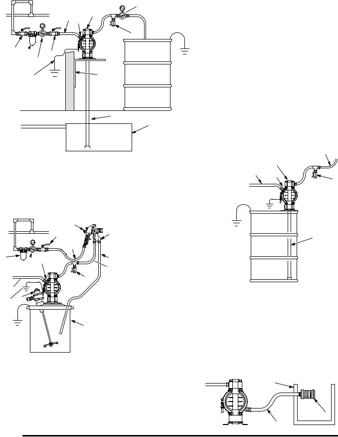
DThe Typical Installations in Fig. 2 are only guides for selecting and installing system components. Contact your Graco distributor for assistance in planning a system to suit your needs.
DAlways use Genuine Graco Parts and Accessories.
DUse a compatible, liquid thread sealant on all male threads. Tighten all connections firmly to avoid air or fluid leaks.
Tightening Threaded Fasteners Before
First Use
Before using the pump for the first time, check and retorque all external fasteners. See Torque Sequence, page 29. After the first day of operation, retorque the fasteners. Although pump use varies, a general guideline is to retorque fasteners every two months.
Toxic Fluid Hazard
Read Toxic Fluid Hazard on page 3.
Use fluids and solvents that are compatible with the equipment wetted parts. Refer to the Technical Data section of all equipment manuals. Read the fluid and solvent manufacturer’s warnings.
 CAUTION
Safe Operating Temperatures
Minimum (all pumps): 40_ F (4_ C) Maximum
Acetal: 180_ F (82_ C) Polypropylene: 150_ F (66_ C)
Aluminum, stainless steel, PVDF: 225_ F (107_ C)
These temperatures are based upon mechanical stress only and may be significantly altered by pumping certain chemicals. Consult engineering guides for chemical compatibilities and temperature limits, or contact your Graco distributor.
Mountings
DThese pumps can be used in a variety of installations. Be sure the mounting surface can support the weight of the pump, hoses, and accessories, as well as the stress caused during operation.
DFig. 2 shows some installation examples. On all installations, mount the pump using screws and nuts.
Pumping High-Density Fluids
High density fluids may prevent the lighter non-metallic check valve balls from seating properly, which reduces pump performance significantly. Stainless steel balls should be used for such applications.
Split Manifolds
Plastic Split Manifold Kits are available to enable you to pump two fluids simultaneously or to mix two fluids in the pump. To order a Split Manifold Kit, use the Part No. from the list below:
241240 polypropylene; split inlet
241241 acetal; split inlet
241242 PVDF; split inlet
241243 polypropylene; split outlet
241244 acetal; split outlet
241245 PVDF; split outlet
4 308981

Installation
Air Line
 WARNING
A bleed-type master air valve (B) is required in your system to relieve air trapped between this valve and the pump. See Fig. 2. Trapped air can cause the pump to cycle unexpectedly, which could result in serious injury, including splashing in the eyes or on the skin, injury from moving parts, or contamination from hazardous fluids.
 CAUTION
The pump exhaust air may contain contaminants. Ventilate to a remote area if the contaminants could affect your fluid supply. Read Air Exhaust Ventilation on page 6.
1.Install the air line accessories as shown in Fig. 2. Mount these accessories on the wall or on a bracket. Be sure the air line supplying the accessories is electrically conductive.
a.The fluid pressure can be controlled in either of two ways. To control it on the air side, install an air regulator (G). To control it on the fluid side, install a fluid regulator (J) near the pump fluid outlet (see Fig. 2).
b.Locate one bleed-type master air valve (B) close to the pump and use it to relieve trapped air. Read the WARNING above. Locate the other master air valve (E) upstream from all air line accessories and use it to isolate them during cleaning and repair.
c.The air line filter (F) removes harmful dirt and moisture from the compressed air supply.
2.Install an electrically conductive, flexible air hose
(C) between the accessories and the 1/4 npt(f) pump air inlet. Use a minimum 1/4 in. (6.3 mm) ID air hose. Screw an air line quick disconnect coupler (D) onto the end of the air hose (C), and screw the mating fitting into the pump air inlet snugly. Do not connect the coupler (D) to the fitting yet.
Installation of Remote Pilot Air Lines
1.Refer to Parts Drawings. Connect air line to pump as in preceding steps.
2.Connect 1/4 in. O.D. tubing to push type connectors (16) on underside of pump.
NOTE: by replacing the push type connectors, other sizes or types of fittings may be used. The new fittings will require 1/8 in. npt threads.
3.Connect remaining ends of tubes to external air signal, such as Graco’s Cycleflo (P/N 195264) or Cycleflo II (P/N195265) controllers.
NOTE: the air pressure at the connectors must be at least 30% of the air pressure to the air motor for the pump to operate.
Fluid Suction Line
DIf using a conductive (acetal) pump, use conductive hoses. If using a non-conductive pump, ground the fluid system. Read Grounding on page 8. The fluid inlet port is 1/2 in. or 3/4 in.
DAt inlet fluid pressures greater than 15 psi
(0.1 MPa, 1 bar), diaphragm life will be shortened.
Fluid Outlet Line
 WARNING
A fluid drain valve (H) is required in your system to relieve pressure in the hose if it is plugged. See Fig. 2. The drain valve reduces the risk of serious injury, including splashing in the eyes or on the skin, or contamination from hazardous fluids when relieving pressure. Install the valve close to the pump fluid outlet.
1.Use electrically conductive fluid hoses (K). The pump fluid outlet is 1/2 in. or 3/4 in. Screw the fluid fitting into the pump outlet snugly. Do not overtighten.
2.Install a fluid regulator (J) at the pump fluid outlet to control fluid pressure, if desired (see Fig. 2). See Air Line, step 1a, for another method of controlling pressure.
3.Install a fluid drain valve (H) near the fluid outlet. Read the WARNING above.
308981 5
Installation
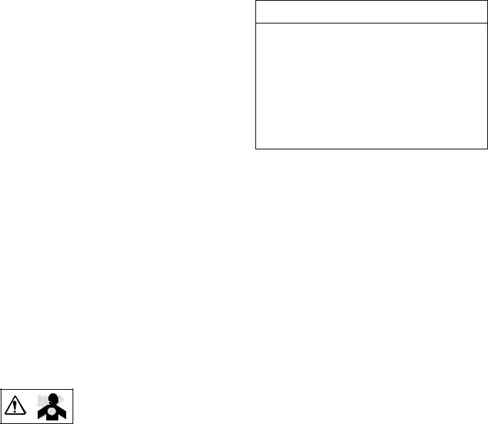
Fluid Pressure Relief Valve
 CAUTION
Some systems may require installation of a pressure relief valve at the pump outlet to prevent overpressurization and rupture of the pump or hose.
See Fig. 1.
Thermal expansion of fluid in the outlet line can cause overpressurization. This can occur when using long fluid lines exposed to sunlight or ambient heat, or when pumping from a cool to a warm area (for example, from an underground tank).
Overpressurization can also occur if the Husky pump is being used to feed fluid to a piston pump, and the intake valve of the piston pump does not close, causing fluid to back up in the outlet line.
1Install valve between fluid inlet and outlet ports.
2Connect fluid inlet line here.
3Connect fluid outlet line here.
3
1
2
|
|
|
|
|
9073A |
|
|
|
|
|
|
|
|
|
|
|
|
|
|
|
|
|
|
|
|
|
|
|
|
|
|
|
|
|
|
Fig. 1 |
|
|
|
|
|
|
|
|
|||
Air Exhaust Ventilation
Read Toxic Fluid Hazard on page 3.
Read Fire and Explosion
Hazard on page 3.
Be sure the system is properly ventilated for your type of installation. You must vent the exhaust to a safe place, away from people, animals, food handling areas, and all sources of ignition when pumping flammable or hazardous fluids.
Diaphragm failure will cause the fluid being pumped to exhaust with the air. Place an appropriate container at the end of the air exhaust line to catch the fluid. See Fig. 2 .
The air exhaust port is 3/8 npt(f). Do not restrict the air exhaust port. Excessive exhaust restriction can cause erratic pump operation.
See Venting Exhaust Air in Fig. 2. Exhaust to a remote location as follows:
1.Remove the muffler (W) from the pump air exhaust port.
2.Install an electrically conductive air exhaust hose
(X) and connect the muffler to the other end of the hose. The minimum size for the air exhaust hose is 3/8 in. (10 mm) ID. If a hose longer than 15 ft (4.57 m) is required, use a larger diameter hose. Avoid sharp bends or kinks in the hose.
3.Place a container (Z) at the end of the air exhaust line to catch fluid in case a diaphragm ruptures. See Fig. 2.
6 308981
Installation
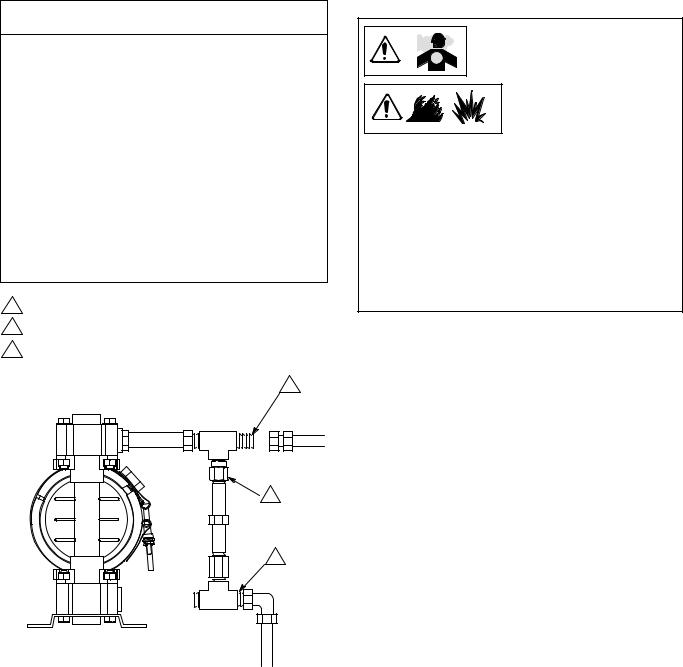
ABOVE-GROUND TRANSFER INSTALLATION
J
C D  A
A 
 K
K
H
E 
 B
B
F G
Y  N
N
L |
9074A |
|
M |
KEY
APump
BBleed-type master air valve (required for pump)
CElectrically conductive air supply line
DAir line quick disconnect
EMaster air valve (for accessories)
FAir line filter
GPump air regulator
HFluid drain valve (required)
JFluid regulator (optional)
KElectrically conductive fluid supply hose
LFluid suction line
MUnderground storage tank
NWall mounting bracket
YGround wire (required; see page 8 for installation instructions)
55-GALLON BUNG PUMP INSTALLATION
AIR SPRAY INSTALLATION
S 
E  P
P  R
R
F  D A
D A 
 T G
T G  K
K
 H C
H C 

Y V
U
KEY
A Pump
CElectrically conductive air supply line
DAir line quick disconnect
H Fluid drain valve (required)
KElectrically conductive fluid supply hose
LFluid suction line
YGround wire (required; see page 8 for installation instructions)
KEY
A Pump
C Electrically conductive air line to pump
EGun air line shutoff valve
FAir line filter
GGun air regulator
HFluid drain valve (required)
K Electrically conductive fluid supply hose
P Circulating valve
RElectrically conductive air line to gun
SAir spray gun
TElectrically conductive fluid return line
U5-gallon pail
VAgitator
YGround wire (required; see page 8 for installation instructions)
A
C D
Y
K
 H
H
L
9075A
9076A
VENTING EXHAUST AIR
KEY
W Muffler |
Z |
|
|
X Electrically Conductive Air Exhaust Hose |
|
Z Container for Remote Air Exhaust |
|
All wetted and non-wetted pump parts must be |
W |
compatible with the fluid being pumped. |
|
|
X |
Fig. 2 |
04054 |
|
308981 7
Installation
Grounding
WARNING
FIRE AND EXPLOSION HAZARD
This pump must be grounded. Before operating the pump, ground the system as explained below. Also read the sec-
tion Fire and Explosion Hazard on page 3.
The acetal Husky 515 pump contains stainless steel fibers, which makes the wetted parts conductive. Attaching the ground wire to the grounding screw (106) grounds the wetted parts. See grounding screw on page 25.
The metal Husky 716 pumps have a grounding strip connecting the vee clamps (109). Attach a ground wire to the grounding strip with the screw, lockwasher, and nut as shown in the Grounding Detail on page 27.
The polypropylene and PVDF Husky 515 pumps are not conductive.
When pumping conductive flammable fluids, always ground the entire fluid system by making sure the fluid system has an electrical path to a true earth ground (see Fig. 3). Never use a polypropylene or PVDF pump with non-conductive flammable fluids as specified by your local fire protection code.
US Code (NFPA 77 Static Electricity) recommends a conductivity greater than 50 x 10–12 Siemans/meter (mhos/meter) over your operating temperature range to reduce the hazard of fire. Consult your fluid supplier to determine the conductivity or resistivity of your fluid. The resistivity must be less than 2 x 10¹² ohm-centimeters.
To reduce the risk of static sparking, ground the pump and all other equipment used or located in the pumping area. Check your local electrical code for detailed grounding instructions for your area and type of equipment.
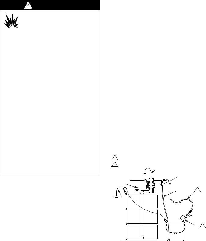
NOTE: When pumping conductive flammable fluids with a polypropylene or PVDF pump, always ground the fluid system. See the WARNING above. Fig. 3 shows a recommended method of grounding flammable fluid containers during filling.
Ground all of this equipment:
DPump: The metal pump has a grounding strip in front of the center housing. The acetal pump has a grounding screw on the top manifold. Connect the non-clamp end of the ground wire to the grounding strip or grounding screw, and connect the clamp end of the ground wire to a true earth ground. To order a ground wire and clamp, order Part No. 222011.
DAir and fluid hoses: Use only electrically conductive hoses.
DAir compressor: Follow the manufacturer’s recommendations.
DSolvent pails used when flushing: Follow the local code. Use only grounded metal pails, which are conductive. Do not place the pail on a non-conduc- tive surface, such as paper or cardboard, which interrupts the grounding continuity.
DFluid supply container: Follow the local code.
GROUNDING A PUMP
KEY
A Pump
H Fluid drain valve (required)
SDispense valve
TFluid drain line
YFluid section grounding via grounding strip or grounding screw (required for metal and acetal pumps)
ZContainer ground wire (required)
1Hose must be conductive.
2Dispense valve nozzle must be in contact with container.
Y
A
 H Y
H Y 

T 1
Z
S 2
|
9079A |
|
Fig. 3 |
||
|
||
|
|
8 308981

Installation
Changing the Orientation of the Fluid Inlet and Outlet Ports (Husky 515)
You can change the orientation of the fluid inlet and outlet ports by repositioning the manifolds. For Husky 515, see Fig. 4. For Husky 716, see Fig. 5.
1. |
Relieve the pressure. See Pres- |
|
sure Relief Procedure on page 10. |
||
|
2.Remove the four manifold nuts (109) or bolts (105).
3.Turn the manifold to the desired position, reinstall the nuts or bolts, and torque to 80 to 90 in-lb
(9 to 10 NSm). See Torque Sequence, page 29.
NOTE: Make sure all manifold o-rings are positioned correctly before you fasten the manifold. Manifold o-rings (139) are shown in Fig. 7 and Fig. 8.
NOTE: Pumps with duckbill check valves are shipped with the inlet manifold on top and the outlet manifold on the bottom. See page 14 for details.
1Torque to 80 to 90 in-lb (9 to 10 NSm). See
Torque Sequence, page 29.
109 1
outlet
inlet
1 109 
9065A
Fig. 4
1Torque to 80 to 90 in-lb (9 to 10 NSm). See
Torque Sequence, page 29.
outlet
1 105
inlet
1 105
9071A
Fig. 5
308981 9
Operation
Pressure Relief Procedure
 WARNING
PRESSURIZED EQUIPMENT HAZARD
The equipment stays pressurized until pressure is manually relieved. To reduce the risk of serious injury from pressurized fluid, accidental spray, or splashing fluid, follow this procedure whenever you
DAre instructed to relieve pressure
DStop pumping
DCheck, clean, or service any system equipment
DInstall or clean fluid nozzles
1.Shut off the air to the pump.
2.Open the dispensing valve, if used.
3.Open the fluid drain valve to relieve all fluid pressure, and have a container ready to catch the drainage.
Flush Pump Before First Use
The pump was tested with water. Prior to first use, flush the pump thoroughly with a compatible solvent.
Reactor feed pumps, part numbers 246484, 246485, and 257447, were tested with lightweight oil, which is left in the fluid passages. To avoid contaminating your fluid with oil, flush the pump with a compatible solvent before using the equipment. Follow the steps under
Starting and Adjusting Pump.
Starting and Adjusting Pump
1. |
Read Toxic Fluid Hazard |
|
on page 3. |
||
|
2.If lifting the pump, follow the Pres-
sure Relief Procedure above.
|
Be sure the pump is |
3. |
properly grounded. |
Read Fire and |
Explosion Hazard on page 3.
4.Check all fittings to be sure they are tight. Use a compatible liquid thread sealant on all male
threads. Tighten the fluid inlet and outlet fittings snugly. Do not overtighten the fittings into the pump.
10 308981
5.Place the suction tube (if used) in the fluid to be pumped.
NOTE: If the inlet fluid pressure to the pump is more than 25% of the outlet working pressure, the ball check valves will not close fast enough, resulting in inefficient pump operation.
6.Place the end of the fluid hose (K) into an appropriate container.
7.Close the fluid drain valve (H).
8.With the pump air regulator (G) closed, open all bleed-type master air valves (B, E).
9.If the fluid hose has a dispensing device, hold it open while continuing with the following step. Slowly open the air regulator (G) until the pump starts to cycle. Allow the pump to cycle slowly until all air is pushed out of the lines and the pump is primed.
If you are flushing, run the pump long enough to thoroughly clean the pump and hoses. Close the air regulator. Remove the suction tube from the solvent and place it in the fluid to be pumped.
Operation of Remote Piloted Pumps
1.Fig. 2 and Parts Drawings. Follow preceding steps 1 through 8 of Starting and Adjusting Pump.
2.Open air regulator (G).
 WARNING
The pump may cycle once before the external signal is applied. Injury is possible. If pump cycles, wait until end before proceeding.
3.Pump will operate when air pressure is alternately applied to push type connectors (16).
NOTE: Leaving air pressure applied to the air motor for extended periods when the pump is not running may shorten the diaphragm life. Using a 3–way solenoid valve to automatically relieve the pressure on the air motor when the metering cycle is complete prevents this from occurring.
Pump Shutdown
At the end of the work shift, relieve the pressure as described in Pressure Relief Procedure at left.
Maintenance
Lubrication
The air valve is lubricated at the factory to operate without additional lubrication. If you want to provide additional lubrication, remove the hose from the pump air inlet and add two drops of machine oil to the air inlet every 500 hours of operation or every month.
 CAUTION
Do not over-lubricate the pump. Oil is exhausted through the muffler, which could contaminate your fluid supply or other equipment. Excessive lubrication can also cause the pump to malfunction.
Flushing and Storage
Flush the pump to prevent the fluid you are pumping from drying or freezing in the pump and damaging it. Use a compatible solvent.
Always flush the pump and relieve the pressure before you store it for any length of time.
Read Pressure Relief Procedure on page 10.
Tightening Threaded Connections
Before each use, check all hoses for wear or damage and replace as necessary. Check to be sure all threaded connections are tight and leak-free.
Check fasteners. Tighten or retorque as necessary. Although pump use varies, a general guideline is to retorque fasteners every two months. See Torque Sequence, page 29.
Preventive Maintenance Schedule
Establish a preventive maintenance schedule, based on the pump’s service history. This is especially important for prevention of spills or leakage due to diaphragm failure.
308981 11
 Loading...