

Graco ChemSafe 515 Instructions - Parts Manual
Instructions-Parts
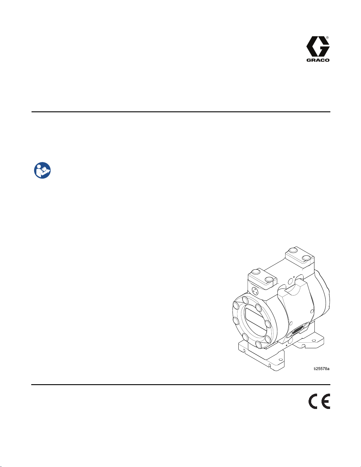
ChemSafe™ 515
Air-Operated
1/2–inch hig
Not approved for use in European explosive atmosphere locations.
100 psi (0.7 MPa, 7.0 bar) Maximum Air
Supply Pressure
100 psi (0.7 MPa, 7.0 bar) Maximum
Fluid Working Pressure
h purity pump for industrial applications. For professional use only.
Important
Read all warnings and instructions in this manual. Save these
instructions.
Safety Instructions
Diaphragm Pump
334794E
EN
PROVEN QUALITY. LEADING TECHNOLOGY.

Contents
Warnings ........................................................... 3
Configuration Number Matrix............................... 6
Installation.......................................................... 8
General Information ..................................... 8
Tighten Bolts ............................................... 8
Tips to Reduce Cavitation............................. 8
Mount The Pump ......................................... 9
Ground The System..................................... 10
Air Lines...................................................... 10
Air Exhaust Ventilation ................................. 11
Fluid Supply Line ......................................... 12
Fluid Outlet Line........................................... 12
Operation........................................................... 13
Tighten Bolts ............................................... 13
Flush the Pump Before First Use .................. 13
Start and Adjust the Pump............................ 13
Pressure Relief Procedure............................ 14
Pump Shutdown .......................................... 14
Maintena
nce ...................................................... 15
Maintenance Schedule................................. 15
Lubrication................................................... 15
Tighten Threaded Connections..................... 15
Flushing and Storage ................................... 15
Troubleshooting.................................................. 16
Repair................................................................ 18
Disassembl
Disassembl
Replace the
Reassemble
Reassemble
Torque Instructions............................................. 23
Parts.................................................................. 24
Kits.................................................................... 27
Dimensions ........................................................ 28
Performance Charts............................................ 29
Technica
l Data ................................................... 31
e the Fluid Section...................... 18
e the Center Section ................... 19
Air Motor................................... 19
the Center Section.................... 20
the Fluid Section....................... 21
2
334794E
Warnings
Warnings
The following warnings are for the setup, use, grounding, maintenance, and repair of this equipment. The
exclamation point symbol alerts you to a general warning and the hazard symbols refer to procedure-specific
risks. When these symbols appear in the body of this manual or on warning labels, refer back to these
Warnings. Product-specific hazard symbols and warnings not covered in this section may appear throughout
the body of this manual where applicable.
WARNING
FIRE AND EX
Flammable fumes, such as solvent and paint fumes, in work area can ignite or explode. To help
prevent fire and explosion:
• Use equipment only in well ventilated area.
• Eliminate all ignition sources; such as pilot lights, cigarettes, portable electric lamps, and
plastic drop cloths (potential static arc).
•Keepwork
• Do not plug or unplug power cords, or turn power or light switches on or off when flammable
fumes are present.
• Ground all equipment in the work area. See Grounding instructions.
•Useonly
• Hold gun firmly to side of grounded pail when triggering into pail. Do not use pail liners unless
they are antistatic or conductive.
• Stop operation immediately if static sparking occurs or you feel a shock. Do not use
equipment until you identify and correct the problem.
• Keepaw
• Route exhaust away from all ignition sources. If diaphragm ruptures, fluid may be exhausted
with air.
c charge may build up on plastic parts during cleaning and could discharge and ignite
Stati
flamma
• Clean plastic parts only in well ventilated area.
• Do not
• Do not operate electrostatic guns in equipment work area.
ble vapors. To help prevent fire and explosion:
PLOSION HAZARD
area free of debris, including solvent, rags and gasoline.
grounded hoses.
orking fire extinguisher in the work area.
cleanwithadrycloth.
PRESSURIZED EQUIPMENT HAZARD
Fluid from the equipment, leaks, or ruptured components can splash in the eyes or on skin
and cause serious injury.
low the Pressure Relief Procedure when you stop spraying/dispensing and before
•Fol
aning, checking, or servicing equipment.
cle
• Tighten all fluid connections before operating the equipment.
• Check hoses, tubes, and couplings daily. Replace worn or damaged parts immediately.
334794E 3
Warnings
WARNING
EQUIPMENT MISUSE HAZARD
Misuse can ca
• Do not operate the unit when fatigued or under the influence of drugs or alcohol.
• Do not exceed
system compo
• Use fluids and solvents that are compatible with equipment wetted parts. See Technical Data
in all equipment manuals. Read fluid and solvent manufacturer’s warnings. For complete
information about your material, request MSDS from distributor or retailer.
• Do not leave the work area while equipment is energized or under pressure.
•Turnoffall
• Check equipment daily. Repair or replace worn or damaged parts immediately with genuine
manufacturer’s replacement parts only.
• Do not alter or modify equipment. Alterations or modifications may void agency approvals
and create safety hazards.
•Makesure
• Use equipment only for its intended purpose. Call your distributor for information.
• Route hoses and cables away from traffic areas, sharp edges, moving parts, and hot surfaces.
• Do not kin
• Keep children and animals away from work area.
• Comply with all applicable safety regulations.
THERMAL
Fluids subjected to heat in confined spaces, including hoses, can create a rapid rise in pressure
due to the thermal expansion. Over-pressurization can result in equipment rupture and serious
injury.
use death or serious injury.
the maximum working pressure or temperature rating of the lowest rated
nent. See Technical Data in all equipment manuals.
equipment and follow the Pressure Relief Procedure when equipment is not in use.
all equipment is rated and approved for the environment in which you are using it.
k or over bend hoses or use hoses to pull equipment.
EXPANSION HAZARD
• Open a valve to relieve the fluid expansion during heating.
• Replace hoses proactively at regular intervals based on your operating conditions.
TIC PARTS CLEANING SOLVENT HAZARD
PLAS
Many solvents can degrade plastic parts and cause them to fail, which could cause serious
injury or property damage.
• Use only compatible water-based solvents to clean plastic structural or pressure-containing
parts.
•SeeTechnical Data in this and all other equipment instruction manuals. Read fluid and
solvent manufacturer’s MSDSs and recommendations.
4
334794E
WARNING
TOXIC FLUID OR FUMES HAZARD
Warnings
Toxic fluids o
inhaled, or s
• Read MSDSs to know the specific hazards of the fluids you are using.
• Route exhaus
the air.
• Store hazardous fluid in approved containers, and dispose of it according to applicable
guidelines.
BURN HAZARD
Equipment surfaces and fluid that’s heated can become very hot during operation. To avoid
severe burns:
• Do not touch hot fluid or equipment.
PERSONAL PROTECTIVE EQUIPMENT
Wear appropriate protective equipment when in the work area to help prevent serious injury,
including eye injury, hearing loss, inhalation of toxic fumes, and burns. This protective
equipment includes but is not limited to:
•Protect
• Respirators, protective clothing, and gloves as recommended by the fluid and solvent
manufacturer.
r fumes can cause serious injury or death if splashed in the eyes or on skin,
wallowed.
t away from work area. If diaphragm ruptures, fluid may be exhausted into
ive eyewear, and hearing protection.
334794E 5
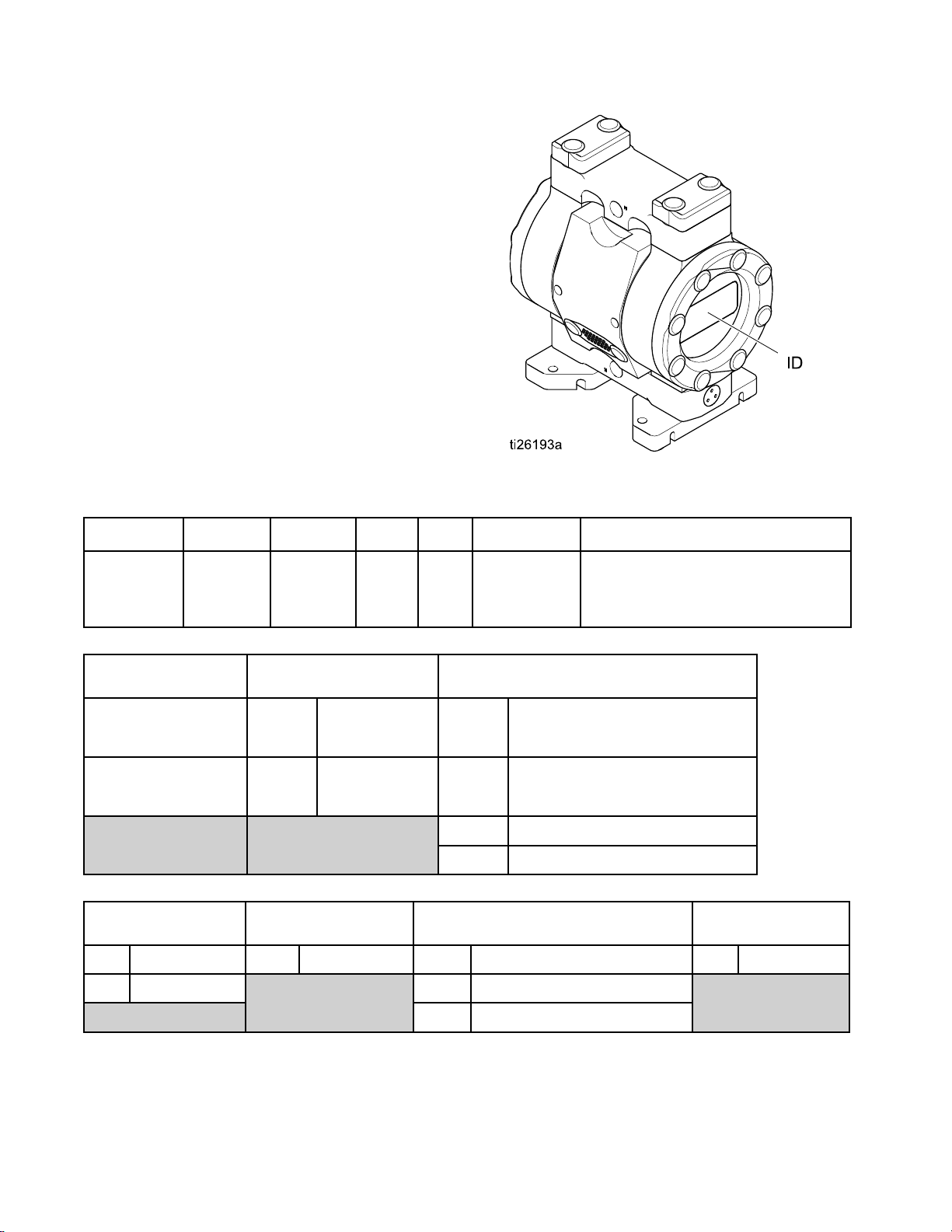
Configuration Nu
mber Matrix
Configuration
Number
Matrix
Check the iden
Configuratio
following ma
pump.
Sample Configuration Number: 515PT-P01APT3PTPTPOPT
515PT P01A PT3
Pump
Model
tification plate (ID) for the
n Number of your pump. Use the
trix to define the components of your
PT PT
Center
Section
and Air
Valve
Fluid
Covers
and
Manifolds
Seats
PO
Balls Diaphragms
PT
Manifold and Seat Seals
Pump
515 PT
1/2 in.
PTFE
515 UH
1/2 in. UHMWPE
Material
Seat
PTFE
PT
UHMWPE
UH
Center Section and Air
Valve Material
opylene
P01A
P03A
Ball Material Diaphragm Material
PT
Polypr
center
air inl
Polypropylene
center with
bspt air inlet
PTFE
with npt
et
Fluid Covers and Manifolds
PT3
PT4
UH3
UH4
BN
EP
PO
PTFE, n
PTFE, bspt
UHMW, npt
UHMW
Buna N
EPDM
PTFE/EPDM Overmolded
pt
,bspt
fold and Seat
Mani
Material
Seal
PTFE
PT
6 334794E

Models
Configuration Nu
mber Matrix
Model Pump
24X426
24X425
24X498
24X497
24X540
24X541
24X496
24X495
1/2 in. PTFE
1/2 in.
UHMWPE
Air & Fluid
Connection
Threads
bspt
npt
bspt
npt
bspt
npt
bspt
npt
Fluid Covers,
Seats, &
Manifolds
PTFE
UHMW
Balls Diaphragm
PTFE/EPDM
Overmolded
PTFE
EPDM
Buna N
Manifold Seal
PTFE
334794E
7

Installation
Installation
General Information
The Typical I
selecting an
your Graco di
system to sui
Graco Parts
are adequat
system’s re
Reference letters in the text, for example (A), refer to
the callouts in the figures.
Variations in color between the plastic components
of this pump are normal. Color variation does not
affect the performance of the pump.
Storage: P
upon deli
Flushing
nstallation shown is only a guide for
d installing system components. Contact
stributor for assistance in planning a
t your needs. Always use Genuine
and accessories. Be sure all accessories
ely sized and pressure rated to meet the
quirements.
umps that are not put into operation
very must be stored appropriately. See
and Storage, page 15.
Tighten Bolts
Before m
first tim
Remove
Torque
Replac
operat
pump ha
in ther
or if t
tempe
ounting and using the pump for the
e, check and retorque all external bolts.
all protective bolt covers (37). Follow
Instructions, page 23, to tighten all bolts.
e the bolt covers (37). After the first day of
ion, retorque the bolts. Retorque the bolts if the
s been idle for an extended time, been used
mal cycling applications, been disassembled,
here is a large difference between environmental
ratures and fluid temperatures.
Tips to Reduce Cavitation
Cavitation i
collapse of b
or excessive
including pi
balls, and s
the pump. Ca
both result
Cavitation depends on the vapor pressure of the
pumped liquid, the system suction pressure, and the
velocity pressure. It can be reduced by changing any
of these factors.
1. Reduce vapor pressure: Decrease the
temperature of the pumped liquid.
2. Increase suction pressure:
a. Lower the
b. Reduce t
c. Increas
3. Reduce
the pum
Pumped liquid viscosity is also very important but
normally is controlled by factors that are process
dependent and cannot be changed to reduce
cavitation. Viscous liquids are more difficult to pump
and more prone to cavitation.
n an AODD pump is the formation and
ubbles in the pumped liquid. Frequent
cavitation can cause serious damage,
tting and early wear of fluid chambers,
eats. It may result in reduced efficiency of
vitation damage and reduced efficiency
in increased operating costs.
installed position of the pump
relative
piping.
length t
fittings
to the liquid level in the supply.
he friction length of the suction
Remember that fittings add friction
o the piping. Reduce the number of
to reduce the friction length.
e the size of the suction piping.
liquid velocity: Slow the cyclic rate of
p.
Graco recommends taking all the above factors
into account in system design. To maintain pump
efficiency, supply only enough air pressure to the
pump to achieve the required flow.
o distributors can supply site specific
Grac
estions to improve pump performance and
sugg
ce operating costs.
redu
8 334794E
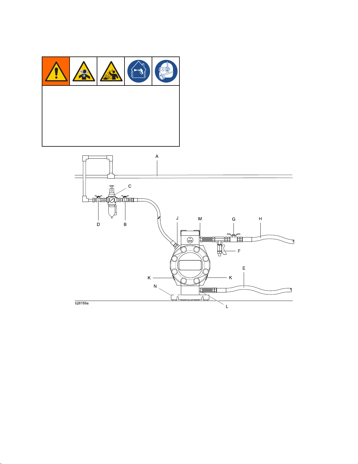
Mount The Pump
To avoid serious injury from toxic fluid or fumes:
• Ventilate to a remote area. The pump
exhaust air may contain contaminants. See
Air Exhaust Ventilation, page 11.
• Never move or lift a pump under pressure. If
dropped, the fluid section may rupture. Always
follow the Pressure Relief Procedure, page 14,
before moving or lifting the pump.
Installation
1. Be sure the mounting surface can support the
weight of the pump, hoses, and accessories, as
well as the stress caused during operation.
2. For all mountings, be sure the pump is secured
with screws through the mounting feet. Always
mount the pump upright.
3. Make sure the surface is flat and that the pump
doesn’t wobble.
4. For ease of operation and service, mount the
pump so air valve, air inlet, fluid inlet and fluid
outlet ports are easily accessible.
Accessories/Components Not Supplied System Components
A Air supply line J
B
C Air filter/regulator assembly
D
E
F
G Fluid shutoff valve
H
Bleed-type master air valve (required
for your pump)
Master air valve (to isolate the
filter/regulator for service)
Grounded flexible fluid supply line
Fluid drain valve (required for your
pump)
Grounded, flexible fluid outlet line
K
L Fluid inlet port
M Fluid outlet port
N
Air inlet port (not visible)
Exhaust port and muffler
Mounting feet
334794E 9
Installation
Ground The Sys
The equipment must be grounded to reduce the
risk of static sparking. Static sparking can cause
fumes to ignite or explode. Grounding provides an
escape wire for the electrical current.
• Always ground the entire fluid system as
described below.
• The pumps are not conductive. Any system
used to pump flammable fluids must be properly
grounded.
• Follow your local fire codes.
Before operating the pump, ground the system as
explained below.
• Pump: Always ground the entire fluid system by
making sure the fluid has an electrical path to a
true earth ground.
• Air and fluid hoses: Use only flexible grounded
hoses with a maximum of 500 ft. (150 m) combined
hose length to ensure grounding continuity.
• Air compressor: Follow manufacturer’s
recommendations.
• Fluid supply container: Follow local code.
• Solvent pails used when flushing: Follow local
code. Use only conductive metal pails, placed
on a grounded surface. Do not place the pail
on a nonconductive surface, such as paper or
cardboard, which interrupts grounding continuity.
tem
Air Lines
1. Install an air
the fluid press
thesameasthe
2. Locate a bleed
the pump and u
sure the valv
and located d
Trapped air can cause the pump to cycle
unexpectedly, which could result in serious
injury from splashing.
3. Locate ano
from all a
them duri
4. An air lin
moisture
5. Install a
the acce
pump air
ID.Ifah
use a lar
regulator and gauge (C) to control
ure. The fluid stall pressure will be
setting of the air regulator.
-typemasterairvalve(B)closeto
se it to relieve trapped air. Be
e is easily accessible from the pump
ownstream from the regulator.
ther master air valve (D) upstream
ir line accessories and use it to isolate
ng cleaning and repair.
e filter (C) removes harmful dirt and
from the compressed air supply.
grounded, flexible air hose (A) between
ssories and the 1/4 npt(f) or 1/4 bspt
inlet. Use a hose with a minimum 1/4 in.
ose longer than 10 ft. (3 m) is required,
ger diameter hose.
Check your system electrical continuity after the
initial installation, and then set up a regular schedule
for checking continuity to be sure proper grounding
is maintained.
10 334794E
 Loading...