


Graco PDW8200, PDW9200, PDW8400, PDW9700, PDW8700 User Manual
...
Instructions–Parts List
321 MM (12.625 IN.) |
308213V |
|
Premier™ Air Motor |
||
EN |
100 psi (0.7 MPa, 7 bar) Maximum Air Input Pressure
Part No. 222800, Series C
Standard Motor
United States Patent Nos. 5,189,943; Des. 345,138; 2,032,617; 5,363,739
Taiwan Patent No. 050264
Canada Patent No. D75390
Korea Patent No. 152224
Other US and Foreign Patents Pending
Important Safety Instructions
Read all warnings and instructions in this manual.
Save these instructions.
See page 2 for Table of Contents.
06818C
Table of Contents
Warnings . . . . . . . . . . . . . . . . . . . . . . . . . . . . . . . . . . . . . |
. 3 |
Air Valve Service . . . . . . . . . . . . . . . . . . . . . . . . . . |
13 |
Installation/Operation . . . . . . . . . . . . . . . . . . . . . . . . . . |
. 6 |
Subplate and Rocker Assemblies . . . . . . . . . . . . |
17 |
Troubleshooting the Air Motor . . . . . . . . . . . . . . . . . . . |
. 8 |
Piston and Piston Rod Seals . . . . . . . . . . . . . . . . |
19 |
Preventive Maintenance Schedule . . . . . . . . . . . . |
8 |
Parts Drawings and Parts Lists . . . . . . . . . . . . . . . . . . |
21 |
Checking for Leaks or Damaged Parts . . . . . . . . . |
8 |
Air Motor . . . . . . . . . . . . . . . . . . . . . . . . . . . . . . . . . |
21 |
Check Chart . . . . . . . . . . . . . . . . . . . . . . . . . . . . . . . |
8 |
Air Valve 222799 . . . . . . . . . . . . . . . . . . . . . . . . . . |
24 |
Service . . . . . . . . . . . . . . . . . . . . . . . . . . . . . . . . . . . . . . |
10 |
Technical Data . . . . . . . . . . . . . . . . . . . . . . . . . . . . . . . . |
26 |
Pressure Relief Procedure . . . . . . . . . . . . . . . . . . |
10 |
Dimensions . . . . . . . . . . . . . . . . . . . . . . . . . . . . . . . . . . . |
27 |
Required Service Tools . . . . . . . . . . . . . . . . . . . . . |
10 |
Graco Standard Warranty . . . . . . . . . . . . . . . . . . . . . . |
28 |
Air Motor Shroud . . . . . . . . . . . . . . . . . . . . . . . . . . |
11 |
Graco Information . . . . . . . . . . . . . . . . . . . . . . . . . . . . . |
28 |
Air Valve Replacement . . . . . . . . . . . . . . . . . . . . . |
11 |
|
|
2 308213
Symbols
Warning Symbol
 WARNING
This symbol alerts you to the possibility of serious injury or death if you do not follow the instructions.
Caution Symbol
 CAUTION
This symbol alerts you to the possibility of damage to or destruction of equipment if you do not follow the instructions.
 WARNING
EQUIPMENT MISUSE HAZARD
Equipment misuse can cause the equipment to rupture or malfunction and result in serious injury.
INSTRUCTIONS
DThis equipment is for professional use only.
DRead all instruction manuals, tags, and labels before operating the equipment.
DUse the equipment only for its intended purpose. If you are uncertain about usage, call your Graco distributor.
DDo not alter or modify this equipment. Use only genuine Graco parts and accessories.
DCheck equipment daily. Repair or replace worn or damaged parts immediately.
DDo not exceed the maximum working pressure of the lowest rated system component. Refer to the Technical Data on page 26 for the maximum working pressure of this equipment.
DUse fluids and solvents which are compatible with the equipment wetted parts. Refer to the Technical Data section of all equipment manuals. Read the fluid and solvent manufacturer’s warnings.
DDo not kink or overbend hoses or use hoses to pull equipment.
DRoute hoses away from traffic areas, sharp edges, moving parts, and hot surfaces. Do not expose Graco hoses to temperatures above 180_F (82_C) or below –40_F (–40_C).
DWear hearing protection when operating this equipment.
DDo not lift pressurized equipment.
DDo not lift the equipment by the Premier air motor lift ring if the total weight of the equipment exceeds 550 lb (250 kg).
DComply with all applicable local, state, and national fire, electrical, and safety regulations.
308213 3
 WARNING
SKIN INJECTION HAZARD
Spray from the gun, hose leaks, or ruptured components can inject fluid into your body and cause extremely serious injury, including the need for amputation. Fluid splashed in the eyes or on the skin can also cause serious injury.
D Fluid injected into the skin might look like just a cut, but it is a serious injury. Get immediate surgical treatment.
DDo not point the gun at anyone or at any part of the body.
DDo not put your hand or fingers over the spray tip.
DDo not stop or deflect leaks with your hand, body, glove or rag.
DDo not “blow back” fluid; this is not an air spray system.
DAlways have the tip guard and the trigger guard on the gun when spraying.
DCheck the gun diffuser operation weekly. Refer to the gun manual.
DBe sure the gun trigger safety operates before spraying.
DLock the gun trigger safety when you stop spraying.
DFollow the Pressure Relief Procedure on page 10 whenever you: are instructed to relieve pressure; stop spraying; clean, check, or service the equipment; and install or clean the spray tip.
DTighten all fluid connections before operating the equipment.
DCheck the hoses, tubes, and couplings daily. Replace worn, damaged, or loose parts immediately. Permanently coupled hoses cannot be repaired; replace the entire hose.
DUse only Graco approved hoses. Do not remove the spring guard that is used to help protect the hose from rupture caused by kinks or bends near the couplings.
MOVING PARTS HAZARD
Moving parts, such as the air motor piston, can pinch or amputate your fingers.
DKeep clear of all moving parts when starting or operating the pump.
DBefore servicing the equipment, follow the Pressure Relief Procedure on page 10 to prevent the equipment from starting unexpectedly.
4 308213

 WARNING
FIRE AND EXPLOSION HAZARD
Improper grounding, poor ventilation, open flames or sparks can cause a hazardous condition and result in a fire or explosion and serious injury.
DGround the equipment and the object being sprayed. Refer to Grounding on page 7.
DIf there is any static sparking or you feel an electric shock while using this equipment, stop spraying immediately. Do not use the equipment until you identify and correct the problem.
DProvide fresh air ventilation to avoid the buildup of flammable fumes from solvents or the fluid being sprayed.
DKeep the spray area free of debris, including solvent, rags, and gasoline.
DElectrically disconnect all equipment in the spray area.
DExtinguish all open flames or pilot lights in the spray area.
DDo not smoke in the spray area.
DDo not turn on or off any light switch in the spray area while operating or if fumes are present.
DDo not operate a gasoline engine in the spray area.
DKeep a fire extinguisher in the work area.
TOXIC FLUID HAZARD
Hazardous fluid or toxic fumes can cause serious injury or death if splashed in the eyes or on the skin, inhaled, or swallowed.
DKnow the specific hazards of the fluid you are using.
DStore hazardous fluid in an approved container. Dispose of hazardous fluid according to all local, state and national guidelines.
DAlways wear protective eyewear, gloves, clothing and respirator as recommended by the fluid and solvent manufacturer.
308213 5

Installation/Operation
 CAUTION
The Premier air motor is designed for intermittent duty cycle applications, such as spraying of corrosion control materials, or adhesive and sealant applications. It is not recommended for continuous duty circulating systems. Contact your Graco distributor for further application information.
NOTE: Reference numbers and letters in parentheses in the text refer to the callouts in the figures and the parts drawings.
NOTE: Always use Genuine Graco Parts and Accessories, available from your Graco distributor. If you supply your own accessories, be sure they are adequately sized and pressure rated for your system.
System Accessories
 WARNING
A bleed-type master air valve and a fluid drain valve are required in your system. These accessories help reduce the risk of serious injury, including fluid injection and splashing of fluid in the eyes or on the skin, and injury from moving parts if you are adjusting or repairing the pump.
The bleed-type master air valve relieves air trapped between this valve and the pump after the air is shut off. Trapped air can cause the pump to cycle unexpectedly. Locate the valve close to the pump.
The fluid drain valve assists in relieving fluid pressure in the displacement pump, hose, and gun. Triggering the gun to relieve pressure may not be sufficient.
Mounting Accessories
Mount the motor to suit the type of installation planned. Motor dimensions and the mounting hole layout are shown on page 27.
If you are mounting the motor on an elevator or a cart, refer to the separate manuals supplied with those components for installation and operation instructions.
Air Line Accessories
The following air line accessories are available from Graco. Contact your Graco distributor for help in designing a system to suit your particular needs.
DA bleed-type master air valve is required in your
system to relieve air trapped between it and the air motor when the valve is closed (see the WARNING
at left). Be sure the bleed valve is easily accessible from the motor, and is located downstream from the air regulator. Order Part No. 113163.
DAn air regulator controls pump speed and outlet
pressure by adjusting the air pressure to the motor. Locate the regulator close to the motor, but upstream from the bleed-type master air valve.
DAn air line filter removes harmful dirt and moisture from the compressed air supply.
DAn air line lubricator adds oil to the compressed air supply at an adjustable rate, to automatically lubricate the air motor.
DA pump runaway valve senses when the pump is running too fast and automatically shuts off the air to the motor. A pump which runs too fast can be seriously damaged. Install closest to the motor air inlet.
6 308213
Installation/Operation
Grounding
WARNING
FIRE AND EXPLOSION HAZARD
Before operating the pump, ground the
system as explained below. Also read the section FIRE AND EXPLOSION HAZARD on page 5.
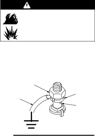
1.Pump: use a ground wire and clamp (supplied). See Fig. 1. Loosen the grounding lug locknut (W) and washer (X). Insert one end of a 1.5 mm@ (12 ga) minimum ground wire (Y) into the slot in lug (Z) and tighten the locknut securely. Connect the other end of the wire to a true earth ground. Order Part No. 237569 Ground Wire and Clamp.
W
X
Y
Z
0864
Fig. 1
2.Air and fluid hoses: use only electrically conductive hoses.
3.Air compressor: follow manufacturer’s recommendations.
4.Spray gun: ground through connection to a properly grounded fluid hose and pump.
5.Fluid supply container: follow your local code.
6.Object being sprayed: follow your local code.
7.Solvent pails used when flushing: follow your local code. Use only metal pails, which are conductive, placed on a grounded surface. Do not place the pail on a nonconductive surface, such as paper or cardboard, which interrupts the grounding continuity.
8.To maintain grounding continuity when flushing or relieving pressure, hold a metal part of the spray gun firmly to the side of a grounded metal pail, then trigger the gun.
308213 7

Troubleshooting the Air Motor
Preventive Maintenance Schedule
The operating conditions of your particular system determine how often maintenance is required. Establish a preventive maintenance schedule by recording when and what kind of maintenance is needed, and then determine a regular schedule for checking your system.
Air Motor Cylinder
Premier motors require lubrication and continuous maintenance including the replacement of the air motor cylinder casting at least every 15,000,000 cycles of use. Use Premier cylinder repair kit 16P239.
Repair or replace the Air Valve assembly (222799) whenever motor stalling or hesitation occurs. This ensures the motor does not overtravel and cause added stress to the cylinder casting.
 WARNING
EXPLOSION HAZARD
Without proper maintenance, the cylinder casting (120026) may fracture unexpectedly due to metal fatigue. This is a potentially hazardous condition and may result in serious injury. The precise life of this casting is difficult to predict
and is affected by the operating pressure, number of cycles, lubrication and air valve maintenance.
Checking the Air Motor for Leaks or Damaged Parts
If the pump is not performing well, the problem could be in the air motor. To check the air motor, perform the following steps.
1.Close the bleed-type master air valve. Disconnect the air line.
2.Remove the shroud. Refer to page 11.
3.Reinstall the air inlet fitting (22). Reconnect the air line.
4.Open the bleed-type master air valve and set the air regulator to about 0.1 MPa, 1 bar (14 psi). Observe the rocker arms and trip rods for smooth operation. Check at points A through E in Fig. 2 by listening or feeling for escaping air, or squirting a small amount of oil around the suspected leak. The oil will bubble if air is leaking. Refer to the sections noted in the Check Chart for detailed service procedures.
Check Chart
NOTE: Service the air valve every 3 million cycles. If the air motor stalls, service the air valve immediately.
Ref. |
Problem |
|
Refer to: |
|
|
Letter |
|
|
|
|
|
|
|
|
|
|
|
A |
Rocker assemblies |
Service |
rocker |
arms |
|
|
(29) not operating. |
(see pages 17 |
and |
||
|
|
|
18). |
|
|
|
|
|
|
|
|
B |
Air escaping |
around |
Service trip rod |
|
|
|
trip rod or push rods. |
and air valve |
|
||
|
|
|
(see pages 11–16). |
||
|
|
|
Service |
push |
rod |
|
|
|
seals (see pages 17 |
||
|
|
|
and 18). |
|
|
|
|
|
|
||
C |
Air escaping |
around |
Service air valve |
||
|
air valve (25). |
|
and air valve gaskets |
||
|
|
|
(see pages 11–16). |
||
|
|
|
|
|
|
D |
Air escaping |
around |
Service |
slide blocks |
|
|
or out of exhaust |
and air |
valve |
seals |
|
|
manifold (45). |
|
(see pages 11–16). |
||
|
|
|
|
||
E |
Air escaping |
around |
Service piston and |
||
|
piston rod (4). |
|
rod seals (see pages |
||
|
|
|
19 and 20). |
|
|
|
|
|
|||
F |
Air motor stalls. |
Service air valve (see |
|||
|
|
|
the NOTE above, and |
||
|
|
|
refer to pages 11–16). |
||
|
|
|
Install the detent, trip |
||
|
|
|
rod, and air valve kits |
||
|
|
|
(see pages 21–24). |
||
|
|
|
|
|
|
8 308213
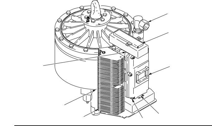
22
29 (under the cover)
A, B |
C (25), F |
|
|
(4) E |
|
|
(45) D |
29 |
|
|
|
Fig. 2 |
A, B |
06547A |
|
|
308213 9
 Loading...