

Graco BULLDOG 222526, BULLDOG 223991, BULLDOG 222539, BULLDOG 223984, BULLDOG 222248 User Manual
...Page 1
INSTRUCTIONS–P
This
manual contains IMPORT
WARNINGS AND INSTRUCTIONS
READ AND RETAIN FOR REFERENCE
ARTS LIST
ANT
306–646
Rev R
Supersedes P
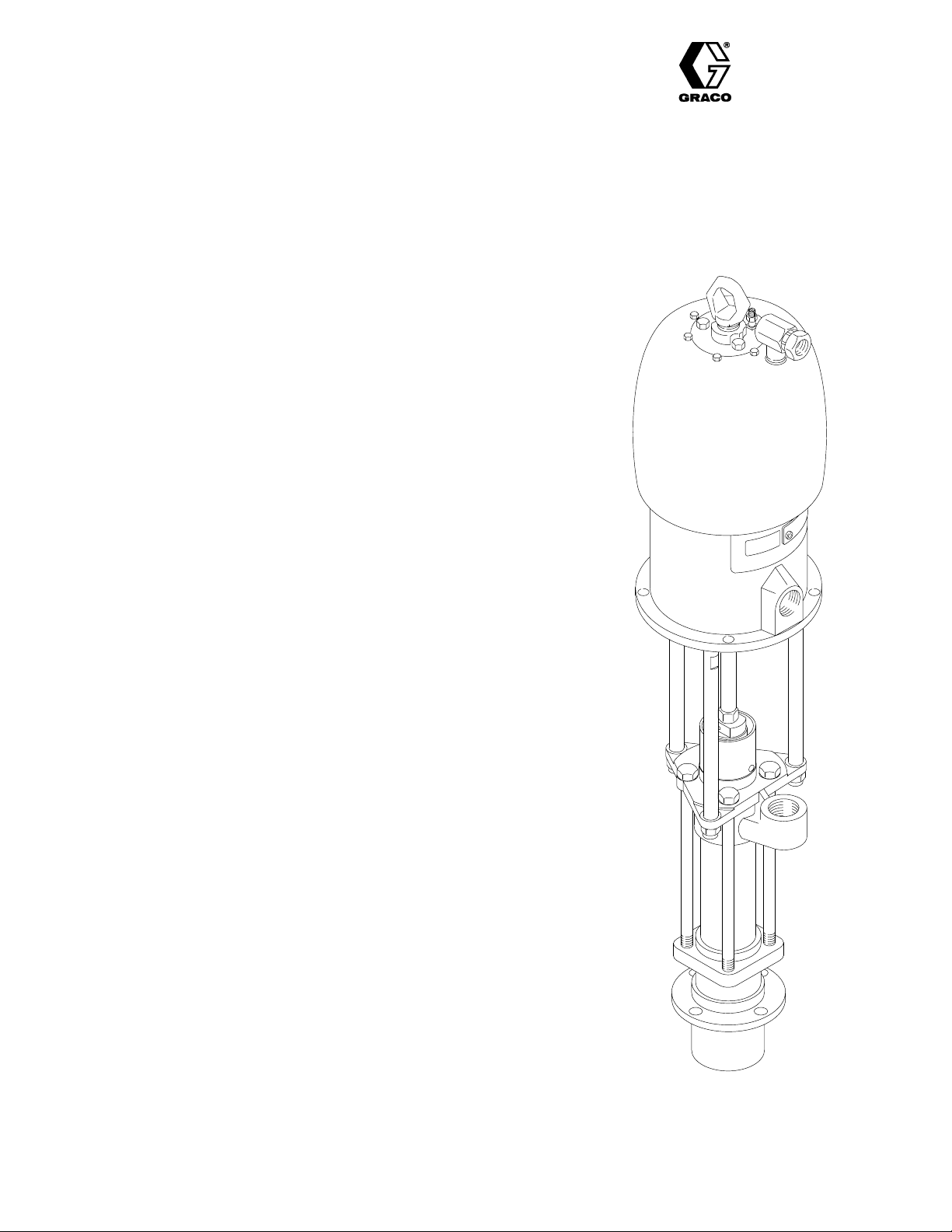
BULLDOG
and KING PUMPS
DRUM LENGTH, WITH PRIMING PISTON
10:1 RATIO BULLDOG PUMPS
100
psi (7 bar) MAXIMUM AIR WORKING PRESSURE
1000 psi (70 bar) MAXIMUM FLUID WORKING PRESSURE
Model 204–287, Series K
With
Standard Air Motor
Model 215–873, Series B
With
Quiet Air Motor
Model 222–526, Series A
With
Standard Air Motor and Severe–Duty Displacement Pump
Model 223–984, Series A
With
Quiet Air Motor and Severe–Duty Displacement Pump
20:1 RATIO KING PUMPS
90
psi (6 bar) MAXIMUM AIR WORKING PRESSURE
1800 psi (124 bar) MAXIMUM FLUID WORKING PRESSURE
Model 222–248, Series A
With
Standard Air Motor
Model 222–539, Series A
With
Standard Air Motor and Severe–Duty Displacement Pump
Model 223–991, Series A
With
Quiet Air Motor and Severe–Duty Displacement Pump
TABLE OF CONTENTS
Warnings 2,
Typical
Installation 4
Operation 5
Maintenance 6
Troubleshooting
Displacement
Parts
Parts
Parts
Parts
How T
Accessories 16–18
Dimensional
Mounting
Technical
Warranty Back
.
. . . . . . . . . . . . . . . . . . . . . . . . . . . . . . . . . . . .
Installation4. . . . . . . . . . . . . . . . . . . . . . . . . . . . . . .
. . . . . . . . . . . . . . . . . . . . . . . . . . . . . . . . . . . . .
. . . . . . . . . . . . . . . . . . . . . . . . . . . . . . . . . . . . . .
. . . . . . . . . . . . . . . . . . . . . . . . . . . . . . . . . . . .
Guide7. . . . . . . . . . . . . . . . . . . . . . . . . . .
Pump Service
Drawing – Standard Pumps
List – Standard Pumps
Drawing – Severe–Duty Pumps
List – Severe–Duty Pumps
o Order Replacement Parts
. . . . . . . . . . . . . . . . . . . . . . . . . . . . . . . .
Drawing
Hole Layout
Data
.
. . . . . . . . . . . . . . . . . . . . . . . .
.
. . . . . . . . . . . . . . . . . . . . . . . . . . . . .
. . . . . . . . . . . . . . . . . .
. . . . . . . . . . . . . . .
. . . . . . . . . . . . . . . . . . . .
. . . . . . . . . . . . . . . .
.
. . . . . . . . . . . .
. . . . . . . . . . . . . . . . . . . . . . . . . .
. . . . . . . . . . . . . . . . . . . . . . . . . .
. . . . . . . . . . . .
Back Cover
8–11.
13, 15
Cover
12.
13.
14.
15.
19.
19.
3
Model
204–287 Shown
GRACO INC. P.O. BOX 1441 MINNEAPOLIS, MN 55440–1441
Page 2

OBSER
SAFETY
HIGH
PRESSURE FLUID CAN CAUSE SERIOUS INJURY. FOR PROFESSIONAL USE ONL
VE ALL W
ARNINGS. Read And Understand All Instruction Manuals Before Operating Equipment.
W
MOVING PARTS HAZARD
KEEP
HANDS AND FINGERS AWAY FROM THE PRIMING PIST
DURING OPERA
WITH
AIR to reduce the risk of injury!
priming
piston extends beyond the intake cylinder
the
pump. The priming
and whenever the pump is charged with air
tion
severely
injure or amputate a hand or finger
it and the intake cylinder
tween
below
cedure,
any
part of the pump.
TION AND WHENEVER THE PUMP IS CHARGED
piston works under extreme force. During opera
. Always
, before checking, clearing, cleaning, flushing or
On the pump downstroke the
to pull the material into
, the priming piston can
, or break a tool, caught be
follow the
Pressure Relief Pro
ON
servicing
FLUID INJECTION HAZARD
General
This
valve,
and
the
on
NEVER
put
hole.
ALWAYS
or
removing the spray tip/nozzle or servicing any system equipment.
NEVER try to stop or deflect leaks with your hand or body
Be sure equipment safety devices are
use.
Medical
If
any fluid appears
CARE AT
exactly
Note
portant
delay
otic
plastic
Spray
Be
use.
malfunction
Safety
Whenever
the
valve
triggering
Trigger
Never
helps
bumped.
Diffuser
The
tion
Follow the Pressure Relief Procedure, to the right, then remove the
spray
gun firmly to the pail. Using the lowest possible pressure, trigger the
spray
place
Safety
equipment generates very high fluid
leaks or ruptured components can inject fluid through your skin
into your body and cause
need for amputation. Also, fluid injected or splashed into the eyes or
the skin can cause serious damage.
point the gun/valve at anyone or
hand or fingers over the spray tip/nozzle, or over the bleeder valve
follow the
Pressure Relief Procedure
extremely serious bodily injury
Alert––Airless Spray W
to penetrate your skin, get
ONCE. DO NOT TREA
what fluid was injected.
to Physician:
to treat the injury surgically as soon as possible
treatment to research toxicity
coatings injected directly into the blood stream. Consultation with a
surgeon or reconstructive hand surgeon may be advisable.
Injection in the skin
Gun/Dispensing V
sure
all gun/valve safety devices are operating properly before each
Do not remove or modify
and result in serious bodily injury
any part of the gun/valve; this can cause a
pressure. Spray from the gun/
, including
at any part of the body
, right, before
.
operating
properly before each
ounds
T AS A SIMPLE CUT
EMERGENCY MEDICAL
is a traumatic injury
. T
oxicity is a concern with some ex
. T
ell the doctor
alve Safety Devices
.
. NEVER
cleaning
.
It is im
. Do
not
Latch
you stop spraying/dispensing, even for a moment, always
gun/valve safety latch in the closed or “safe” position, making the gun/
inoperative. Failure to set the safety latch can result in accidental
of the gun/valve.
set
Guard (only on spray guns)
operate the spray gun with the trigger guard removed. This guard
prevent the spray gun from triggering accidentally if it is dropped or
(only on spray guns)
spray gun dif
when the tip is not installed. Check the dif
tip. Aim the spray gun into a grounded metal pail, holding the spray
gun. If
the dif
fuser breaks up spray and reduces the risk of fluid injec
the fluid emitted is not dif
fuser immediately
.
fuser operation regularly
fused into an irregular stream, re
ARNINGS
The air motor piston (located behind the air motor shield) also moves
when
air is supplied to the motor
motor
shield removed.
Relief
-
-
-
Procedure
Tip
Guard (only on spray guns)
ALWAYS
tip
does
of
Spray T
Use
spray
safety
dure
NEVER
fully relieved and the gun/valve safety latch is engaged.
have the tip guard in place on the spray gun while spraying. The
guard alerts you to the fluid injection hazard and
not prevent,
your body close to the spray tip.
ip/Nozzle Safety
extreme caution when cleaning or
tip/nozzle clogs while spraying/dispensing, engage the
latch immediately
and then remove the spray tip/nozzle to clean it.
wipe of
Pressure
To
reduce the risk of serious bodily injury
splashing
-
-
.
-
always follow this procedure whenever you shut of f the pump,
when
tem,
whenever
1.
2.
3. Close
4. Disengage
5. Hold a metal part of the gun/valve firmly to the side of a
6. Engage
7. Open
8. Leave
If you suspect that the spray tip/nozzle or hose is completely
clogged,
the steps above, VERY SLOWL
nut,
then
in the eyes or on the skin, or injury from moving parts,
checking or servicing any part of the spray/dispensing sys
when installing, cleaning
you stop spraying/dispensing.
Engage the gun/valve safety latch.
Shut of
the bleed–type master air valve (required in your sys
tem).
grounded
sure.
the drain
in
your system), having a container ready to catch the drain
age.
the drain valve open until you are ready to
pense
again.
or that pressure has not been fully relieved after following
nozzle, or hose end coupling and relieve pressure
loosen completely
Before servicing the pump, follow the
below to prevent the pump
the risk of accidentally placing your fingers or any part
f build–up around the spray tip/nozzle until pressure is
Relief Procedure
f the air to the pump.
the safety latch.
metal pail,
the gun/valve safety latch.
valve and/or the pump bleeder valve (required
. NEVER operate the pump
from starting accidentally
helps reduce,
changing spray tips/nozzles. If the
. ALWAYS follow the
or changing spray tips/nozzles, and
and trigger the gun/valve to relieve pres
Y loosen the tip guard retaining
. Now clear the tip/nozzle or hose.
Pressure Relief Proce
, including fluid injection,
Y.
with the air
Pressure
gun/valve
spray/dis
gradually
.
but
-
-
-
-
-
-
,
306–646
Page 3

EQUIPMENT MISUSE HAZARD
General
Any
overpressurizing,
ids, or using worn or damaged parts, can cause them to rupture and result
in
fluid injection, splashing in the eyes or on the skin, or other serious bod
ily
NEVER
to
malfunction.
CHECK
worn
Always
ommended
Safety
misuse of
injury
or damaged parts immediately
the spray/dispensing equipment or accessories, such as
modifying parts, using incompatible chemicals and flu
, or fire, explosion or property damage.
alter or modify any part of this equipment; doing so
all spray/dispensing equipment
wear protective eyewear
by the fluid and solvent manufacturer
regularly and repair or replace
.
, gloves, clothing and
could cause it
respirator as rec
.
-
-
-
HOSE SAFETY
High
pressure fluid
ops
a leak,
high
pressure spray emitted from it can cause a fluid injection injury or
other
serious bodily injury or property damage.
ALL
FLUID HOSES USED WITH A FLEXING MOTION MUST
SPRING GUARDS ON BOTH ENDS!
the
hose from kinks or bends at or close to the coupling which can result
in
hose rupture.
TIGHTEN
fluid can dislodge a loose coupling or allow high pressure spray to be
emitted
from the coupling.
NEVER
use a damaged hose. Before each use, check the entire hose
cuts, leaks,
couplings.
DO
NOT try to recouple high pressure hose or mend it with tape or any
other
device.
fluid.
in the hoses can be very dangerous. If the hose devel
split or rupture due to any kind of wear
The spring guards help protect
all fluid connections securely before each use. High pressure
abrasion,
If any of
bulging cover
these conditions exist, replace the hose immediately
A repaired hose cannot safely contain the high pressure
, or damage or movement of the hose
, damage or misuse, the
HA
-
VE
for
.
FIRE OR EXPLOSION HAZARD
Static
electricity is created by the flow of fluid through the pump and hose.
If every part of the spray/dispensing equipment is not
sparking
may also occur when plugging in or unplugging a power supply cord.
Sparks
particles
pensing
ous bodily injury and property damage. Do not plug in or unplug any
power supply cords in the spray/dispensing area when there is any
chance
If
this
tem
has
may occur
can ignite fumes from solvents and the fluid being sprayed, dust
and other flammable substances, whether you are
indoors or outdoors, and can cause a fire or explosion and seri
of igniting fumes still in the air
you experience any static sparking or even a slight shock while using
equipment, STOP SPRA
for proper grounding. Do not use the system again until the problem
been identified and corrected.
, and the
system may become hazardous. Sparking
.
YING IMMEDIA
To ground the pump:
To ground the pump, loosen the grounding lug locknut (W) and
washer
(X). Insert one end of a 1.5 mm@ (12 ga) minimum ground
wire
(Y) into the slot in lug (Z) and tighten the locknut securely
Fig 1. Connect the other end of the wire to a true earth ground. See
ACCESSORIES
on page 16 to order a ground wire and clamp.
Y
W
Fig
1
X
properly
spraying/dis
TELY.
Check the entire sys
Z
grounded,
-
-
-
. See
System
The
ING
velops
(6
Be
withstand
the
the
Fluid
BE
the
ways
this
HANDLE
move
ner
peratures
Pressure
10:1 Bulldog Pump develops
PRESSURE
1800 psi (124 bar) MAXIMUM
bar) air pressure. Never exceed these pressures.
sure that all
maximum
system.
at 100 psi (7 bar) air pressure. The 20:1 King Pump de
spray/dispensing equipment and accessories are rated to
the maximum working pressure of the pump. DO NOT
working pressure of any component or accessory used in
1000 psi (70 bar) MAXIMUM WORK
WORKING PRESSURE
at 90 psi
exceed
Compatibility
SURE that all fluids and solvents used are chemically compatible with
wetted parts shown in the
read the manufacturer’s literature before using fluid or solvent
pump.
AND ROUTE HOSES CAREFULLY. Do not pull on hoses to
equipment. Do not use fluids which are not compatible
tube and cover of the hose. DO NOT expose Graco hoses to tem
above 82
_ C
TECHNICAL DATA on the back cover. Al
(180
_ F)
or below –40
_ C
(–40
with the in
_ F).
Hose Grounding Continuity
Proper
hose grounding continuity is essential to maintaining a grounded
spray
system. Check the electrical resistance of your air and fluid hoses
at
least once a week. If your hose does not have a tag on it which speci
fies the maximum electrical resistance, contact the hose supplier or
manufacturer
in
the appropriate range for your hose to check the resistance. If the
tance
grounded
Also,
for the maximum resistance limits. Use a resistance meter
exceeds the
or poorly
read
recommended limits, replace it immediately
grounded hose can make your system hazardous.
FIRE OR EXPLOSION HAZARD
, below
.
resis
. An un
Grounding
To reduce the risk of static sparking, ground the pump, object being
sprayed,
spray/dispensing area. CHECK your local electrical code for detailed
grounding
ground
1.
2.
3.
4.
5.
6.
7.
8.
9.
Flushing
Before
grounded. Refer to Grounding, above. Follow the Pressure Relief
Procedure on page 2, and remove the spray tip/nozzle from the
gun/valve.
firm
flushing to reduce the risk of fluid injection injury , static sparking and
splashing.
and all other spray/dispensing equipment used or located in the
instructions for your area and type of equipment. BE SURE to
all of this spray/dispensing equipment:
Pump:
use a ground wire and clamp. See Fig 1.
Air hoses:
Fluid hoses:
Air compressor:
Spray gun/dispensing valve:
nection
Fluid supply container:
Object being sprayed:
All
Use only metal pails, which are conductive, placed on a grounded
surface.
paper
T
o maintain grounding continuity when flushing
sure
grounded
use only grounded air hoses.
use only grounded fluid hoses.
follow manufacturer’s recommendations.
to a properly grounded fluid hose and pump.
solvent pails used when flushing,
Do not place the pail on a nonconductive
or cardboard, which interrupts the grounding continuity
,
always hold a metal part of the gun/valve firmly to the side of a
metal
pail, then trigger the gun/valve.
grounding is obtained through con-
according to your local code.
according to your local code.
according to your local
surface, such as
or relieving pres
code.
.
Safety
flushing, be sure the
Always use the lowest possible fluid pressure, and maintain
metal–to–metal contact between the gun/valve and
entire system and flushing pails are properly
the pail during
-
-
-
in
-
-
-
-
-
-
IMPORTANT
United
States Government safety standards have been adopted under the Occupational Safety and Health Act. These standards – particularly the Gen
eral
Standards, Part 1910, and the Construction Standards, Part 1926 – should be consulted.
306–646
-
3
Page 4

INSTALLATION
M
TYPICAL
Y
INST
ALLATION
F
E
K
D
J
A
C
G
B
L
H
4
N
KEY
A
Air Supply Hose to Pump
B
Air Line Filter
C
Air Regulator and Gauge
D Bleed–T
E
F
G Bleed–T
H
J
K
L
M
N
Y
4
ype Master Air V
Air Line Lubricator
Pump Runaway V
ype Master Air V
Fluid Drain V
Air–Powered Ram
Gun/Dispensing V
Grounded Fluid Supply Hose
Whip Hose
Air Supply Hose to Ram
Pump Ground Wire
Pump Bleeder V
alve
alve
alve
alve
alve
alve
The
reference numbers and
callouts
See
in Figures 1–3 and the Parts Drawings.
pages 16–18 for accessories
letters in the text refer to the
available from Graco.
Be sure all accessories are properly sized to withstand
the
pressures in the system.
The Typical Installation shown above is only a guide to
selecting and installing required and optional accessories. For assistance in designing a system to suit your
particular
needs, contact your Graco representative.
The Dimensional Drawing on page 19 provides necessary
measurements for mounting the pump. If you use an
accessory ram (J), as shown in the T ypical Installation,
refer
to the separate ram manual for mounting dimension
requirements.
System
Accessories
Install the air line accessories in the order shown in the
Typical
inlet, install a pump
Installation. W
runaway valve (F) to shut of
orking upstream from the pump air
f the air to
the pump if the pump accelerates beyond the preadjusted setting. A pump which runs too fast can be seriously
damaged.
Next,
install an air line lubricator (E) for automatic air
mo
tor lubrication, a bleed–type master air valve (D) to relieve
air trapped between the valve
regulator
(C) to control pump
and the pump, an air
speed, and an air line filter
(B) to remove harmful dirt and moisture from the compressed air supply. Install a second bleed valve (G) on
the
pump air line to isolate the accessories for servicing.
Be
sure the pump air line (A) is properly grounded, and is
large
enough to supply
an adequate volume of air to the
motor. An air–powered ram (J) requires a separate
grounded
4
air supply line (N).
306–646
WARNING
Two accessories are required in your system: a
bleed–type master air valve (D) and a fluid drain
valve
(H).
These accessories help reduce the risk of
serious bodily injury including fluid injection, splash
ing
in the eyes or on the skin, and injury from moving
parts
if you are adjusting or repairing the pump.
The
bleed–type master air valve
between
this valve and
the pump after the air is shut
relieves air trapped
off. Trapped air can cause the pump to cycle unex
pectedly.
The
sure
triggering
be
Install
Locate the valve close to the pump.
fluid drain valve
in
the displacement pump, hose and spray gun;
assists in relieving fluid pres-
the spray gun to relieve pressure may not
suf
ficient.
a fluid drain valve (H) close to the pump fluid
Then connect a grounded fluid supply hose (L). Between the fluid supply hose (L) and the gun/dispensing
valve
(K), install a whip hose (M) for greater flexibility
-
NOTE: To
use the optional fluid outlet at the base of
air
motor
, connect a riser tube between the stan
dard
outlet and the optional outlet.
GROUNDING
WARNING
Before operating the pump, ground the system as
explained under FIRE OR EXPLOSION HAZARD
and
Grounding
on page 3.
-
-
outlet.
.
the
-
Page 5

OPERATION
WARNING
Pressure Relief Procedure
To
reduce the risk of serious bodily injury
fluid
injection, splashing in the eyes or on the skin,
or injury from moving parts, always follow this pro
cedure whenever you shut of f the pump, when
checking or servicing any part of the spray/dispensing system, when installing, cleaning or
changing spray tips/nozzles, and whenever you
stop
spraying/dispensing.
1.
Engage the gun/valve safety latch.
2.
Shut of
3. Close the bleed–type master air valve (re-
quired
4.
Disengage the gun/valve safety latch.
5. Hold
side of a grounded metal pail, and trigger the
gun/valve
6.
Engage the gun/valve safety latch.
7. Open
valve (required in your system), having a container
8. Leave
to
f the air to the pump.
in your system).
a metal part of the gun/valve
to relieve pressure.
the drain valve and/or the pump bleeder
ready to catch the drainage.
the drain valve open until you are ready
dispense again.
, including
-
firmly to the
If you suspect that the spray tip/nozzle or hose is
completely
clogged, or
that pressure has not been
fully relieved after following the steps above,
VERY
SLOWL
nozzle
or hose end coupling and relieve pressure
gradually, then loosen completely. Now clear the
tip/nozzle
Moving
other body parts. When the pump is operating, the
priming
air
move. Therefore, NEVER operate the pump with
the
and
Before attempting to clear an obstruction from the
priming
sure
the pump from starting accidentally
Flush the Pump Before Using
This pump was tested with lightweight motor oil which
was
nation of the fluid being pumped, flush the pump with a
compatible solvent before using it. If the pump is being
used
circulate
Keep the packing nut/wet–cup (21) one–half full with
Graco
being
damaging the packings.
parts can pinch or amputate your fingers or
piston (located at the pump intake) and the
motor piston (located behind the air motor
air motor shield removed, and keep your fingers
hands away from the priming piston.
piston or service the pump, follow the
Relief Procedure W
left in to protect the pump parts. To prevent contami
to supply a circulating
until
Throat Seal Liquid (TSL), to help prevent the fluid
pumped from drying on the displacement rod and
Y loosen
or hose.
the pump and lines are thoroughly flushed.
the tip guard retaining nut,
WARNING
arning
system, allow the solvent to
above to prevent
.
shield)
Pres
-
Starting and Adjusting the Pump
1. Make
2.
3.
4. Slowly
5. If
To reduce the risk of fluid injection, DO NOT use
your
priming
6. Release
7. In
To
fluid injection and splashing in the eyes or on the
skin,
mum air and fluid working pressure of the lowest
rated
MISUSE
Never allow the pump to run dry of the fluid being
pumped. A dry pump will quickly accelerate to a high
speed, possibly damaging itself. If your pump accelerates
check the fluid supply. If the supply container is empty
and
and
with
the
NOTE: A pump runaway valve (F) can be installed on
sure the air regulator
pump
bleeder valve (4) are closed.
Open the bleed–type master air valve (D).
Hold a metal part of the gun/valve firmly to the side of
a
grounded metal pail, and trigger the gun/valve.
open the air regulator
running
Cycle
the
valve
dle can come
something other than your hand or fingers and
use
bleeder
pump
as
ing system, it will run continuously and speed up or
slow
lowest
sults.
reduce the risk of serious bodily injury
quickly
air has been
the lines with fluid, or flush the pump and leave it filled
a compatible solvent. Be sure to eliminate all air from
fluid system.
slowly and smoothly (about 20 psi [1.4 bar]).
the pump slowly until all the air is purged from
pump and lines.
the pump is not
(4) slightly
it as a priming valve until the fluid appears at the
hole. Close the bleeder valve.
hand or fingers to cover the bleeder hole when
the pump.
the trigger and
will stall against pressure.
a direct supply system, the pump will start and stop
the gun/valve is opened
down as the system demands. Always use the
pressure necessary to obtain the desired re
and property damage, never
component in your system.
HAZARD, System Pressure,
, or is running too fast, stop it immediately and
the
air line to automatically shut of
starts
to run too fast.
priming properly
. Do not open it all the way; the han
of
f. Cover the bleeder valve hole with
WARNING
WARNING
pumped into the lines, prime the pump
(C), drain valve (H), and
(C) until the pump starts
, open the bleeder
engage the safety latch. The
and closed. In a circulat
exceed the maxi
See EQUIPMENT
-
-
-
, including
-
on page 3.
f the pump if it
306–646
5
Page 6

MAINTENANCE
Shutdown and Care of the Pump
Always
on page 7 whenever you shut of f the pump. Stop the
pump
on the exposed displacement rod and damaging the
throat
Every
wet–cup
dure
overtighten
Always
and hoses. If the pump is to be stored for any period of
time,
the pump with water, then with mineral spirits to protect
the
Flushing
To
or splashing in the eyes or on the skin, follow the Pres-
sure
the spray tip (spray guns only) before flushing
follow the
at the bottom of its stroke to keep fluid from drying
packings.
40 hours of operation, check that the packing nut/
(21) is tight. Follow the Pressure Relief Proce
W
arning
flush the pump before the fluid dries
and
you are pumping water–based fluid, first flush
pump parts.
reduce the risk of fluid injection injury
Relief Procedure W
Pressure
on page 7 first. T
or the packings may be damaged.
Relief Procedure W
ighten just snug – do not
, static sparking,
arning
on page
7, and
in the pump
arning
remove
. Hold a
metal part of the gun/valve firmly to the side of a
grounded
pressure
Lubrication
The accessory air line lubricator (E) provides automatic
air motor lubrication. For daily , manual lubrication, disconnect
machine
-
and
Corrosion Protection
Water, or even moist air , can cause your pump to
corrode.
pump
flush the pump again with mineral spirits or oil–
based
eral spirits in the pump. Be sure to follow all steps
of the Pressure Relief Procedure W arning on
page
metal
pail and use the lowest possible fluid
during flushing.
the air regulator (C), place about 15 drops of
oil in the pump air inlet, reconnect the
turn on the air supply to blow oil into the motor
WARNING
T
o help prevent corrosion, never leave the
filled with water or air
solvent, relieve pressure, and leave the min
7.
. After normal
light
regulator
.
flushing,
-
6
306–646
Page 7

TROUBLESHOOTING GUIDE
WARNING
Pressure
To
tion,
parts,
pump,
pensing
tips/nozzles,
1.
2.
3. Close the bleed–type master air valve (required in your
4. Disengage
5. Hold a metal part of the gun/valve firmly to the side of a
Relief Procedure
reduce the risk of serious bodily injury, including fluid injec
splashing in the eyes or on the skin, or injury from moving
always follow this procedure whenever you shut of
when checking or servicing any part
of the spray/dis
f the
system, when installing, cleaning or changing spray
and whenever you stop spraying/dispensing.
Engage the gun/valve safety latch.
Shut of
f the air to the pump.
system).
the safety latch.
grounded
metal
pail, and trigger the gun/valve to relieve
pressure.
-
-
6. Engage
7. Open
quired
the
8. Leave
system
If
you suspect that the spray tip/nozzle or
clogged,
the gun/valve safety latch.
the drain valve and/or the pump bleeder valve (re
in your system), having a container ready to catch
drainage.
the drain valve open until you are ready to use the
again.
or that pressure has not
lowing the steps above, VER
retaining
sure
zle
nut, nozzle, or hose end coupling and relieve pres
gradually
or hose.
been fully relieved after fol
Y SLOWL
, then loosen completely
hose is completely
Y loosen the tip
guard
. Now clear the tip/noz
-
-
-
-
NOTE: Check
PROBLEM SOLUTION
Pump fails to operate
Pump operates but output
low on both strokes
everything in the troubleshooting guide below before disassembling the pump.
CAUSE
Exhausted
Restricted line or inadequate air supply
Insufficient air pressure, closed or clogged air
valves,
Obstructed fluid hose or gun/valve
Fluid dried on the displacement rod
Dirty or worn air motor parts
Exhausted fluid supply
Restricted line or inadequate air supply
Insufficient air pressure, closed or clogged air
valves,
Obstructed fluid hose or gun/valve
Bleeder valve open or worn
Air leaking into supply drum
Fluid too heavy for pump priming
W
fluid supply
etc.
etc.
orn throat packings in displacement pump
Refill and reprime or flush.
Clear; see
Open, clear
Clear.*
Clean. See
Clean, service. See air motor manual, supplied.
Refill and reprime or flush.
Clear
. See
Open, clear
Clear.*
Close; replace.
Check inductor or ram plate seal.
Use
pump bleeder valve (see page 5). Use inductor or
ram
unit.
Replace gland/packing stack.
TECHNICAL DATA on back cover
.
SERVICE.
TECHNICAL DATA on back cover
.
.
.
Pump
operates but output
low on downstroke
Pump operates but output
low on upstroke
Erratic or accelerated
pump speed
*To
clear the pump, follow the
air
is turn on, then the fluid hose or gun/valve is obstructed.
Fluid too heavy for pump priming
Held open or worn intake valve or packings
Held open or worn piston valve or packings
Exhausted fluid supply
Fluid too heavy for pump priming
Held open or worn piston valve or packings
Held open or worn intake valve or packings
W
orn throat packings in displacement pump
Pressure Relief Procedure W
arning,
Use
pump bleeder valve (see page 5). Use inductor or
ram
unit.
Clear valve; replace gland/packing stack.
Clear valve; replace gland/packing stack.
Refill and reprime or flush.
Use
pump bleeder valve (see page 5). Use inductor or
ram
unit.
Clear valve; replace packings.
Clear valve; replace gland/packing stack.
Replace gland/packing stack.
above. Disconnect the fluid line. If the pump starts when the
306–646
7
Page 8

DISPLACEMENT PUMP SERVICE
WARNING
Moving
other
priming
air motor piston (located behind the air motor
shield)
with the air motor shield removed, and keep your
fingers
Before attempting to clear an obstruction from the
priming
sure
vent
parts can pinch or amputate your fingers
body parts. When the pump is operating, the
piston (located at the pump intake) and the
move.
Therefore, NEVER operate the pump
and hands away from the priming piston.
piston or service the pump, follow the
Relief Procedure W
the pump from starting accidentally
arning
on page 7 to pre
Pres-
.
or
-
Before You Start (All Models)
1. Repair Kit 220–861 is available. See pages 13 and
15.
For the best results, use all the new parts in the
kit,
even if the old ones look good. Repair kit parts are
indicated
for
2. To reduce down time, keep spare parts on hand.
Recommended
list
3. The gland/packing stacks (64*, 65*) are preassembled.
stalling
4. For air motor service and parts information, refer to
manual
306–968
for motor Model 215–255, or manual 307–741 for
motor
5. If
possible, flush the pump before service
patible solvent. Follow the Pressure Relief Proce-
dure
tom
6. Disconnect
mounting
in the text
example (27*).
with a double asterisk, for example (41**).
Do not disassemble the stacks when in
them in the pump.
307–049 for motor Model 208–356, manual
for motor Model 206–647, manual 307–304
Model 220–106.
W
arning
of its stroke.
all
and clamp it in a vise.
and the parts list with an asterisk,
spare parts are indicated
on page 7. Stop the pump at the
the hoses. Remove the pump from its
in the parts
with a com
bot
Model 204–641 Displacement Pump (Used on
Models 204–287, 215–873 and 222–248)
Disassembly
NOTE: Refer
1. Remove the cotter pin (41). Unscrew the coupling
nut (50) and the three tie rod locknuts (44). Pull the
displacement pump (2) off the air motor (1).
2. Remove
Unscrew the connecting rod (53) from the upper cap
(33).
3. Insert
packing nut/wet–cup (21), and loosen it. Push the
displacement rod (18) down until the priming piston
(37) clears the intake valve housing (28). Remove
the
plate
4. Unscrew
housing (28) off the pump. Pull the priming rod (32)
and displacement rod (18) out of the bottom of the
cylinder (39). Remove the pin (7) and unscrew the
priming
306–646
8
to Fig 2 and the parts drawing.
the cotter pin (42). Loosen the locknut (45).
a 1/4 in. (6 mm) diameter rod in the
nut (6), priming piston (37), valve plate (36)
guide (31).
the four tie
rod (32) from the connecting rod (20).
bolts (8) and pull the intake valve
holes of the
and
5. Pull
6. Disassemble
7. Unscrew
8. Unscrew
9. Clean
the cylinder (39) down out of the outlet housing
(26).
Inspect the inner surface of the cylinder and
outer surface of the displacement rod (18) for
scratches or scoring, which can cause premature
packing
the
all parts, replacing as necessary . Check the intake
valve
(20). Pull the
(19),
necting
wiper
outlet
wear and leaking. To check, run a finger over
surface
or hold the part up to the light at an angle.
the intake valve (3). Clean and inspect
seat (30) for nicks or damage.
the upper cap (33) from the connecting rod
displacement rod (18) of
and remove the piston assembly from the con
rod. Disassemble the piston.
the packing nut/wet–cup (21). Remove the
seal (66). Remove the throat
housing (26).
and inspect all parts, replacing as necessary
packings from the
Reassembly
NOTE: Refer to Fig 2 and the parts drawing during the
following
1. See
-
2. See Detail B of Fig 2. Install the two bearings (35*)
-
-
3. Install
4. Insert
5. Install
6. Install
7. See Detail C of Fig 2. Slide the intake valve gland/
8. Install two copper gaskets (27*) on the intake valve
Detail A of Fig 2. The gland/packing stack
for
the throat is preassembled.
the
stack.
stall it into the outlet housing
the v–packings are facing down.
seal (66) in the groove of the wet–cup (21)
lips
facing down
cup (21).
and the u–cup packing (56*) on the piston (38).
sure
the lips of the packing are facing up.
small
o–ring (15) in the lower cap (19) and the larger
o–ring
the piston (38), valve plate (34), and lower
(19)
on the connecting rod (20).
the connecting rod (20) into the displacement
rod
(18) so the lower cap (19) fits into the bottom of
the displacement rod. Screw the top cap (33) onto
the
connecting rod (20) until it is tight against the top
of
the displacement rod (18).
one copper gasket (27*) in
(26). Screw the priming rod (32) into the connecting
rod (20) and secure with the pin (7). Push the displacement rod (18) and priming rod (32) up into the
outlet
housing (26)
just protrudes from the packing nut/wet–cup (21).
Lubricate the priming rod (32).
the cylinder (39) in the outlet housing (26), be
ing careful not to scratch the polished inner surface
of
the cylinder
packing
(3). Do not disassemble the stack.
of
the v–packings are facing up.
nut
(1
1). Install the valve seat
housing (28). Place the intake valve seal housing (3)
on
the seat (30).
stop
(29). Install the stop
(28).
procedure.
Do not disassemble
Lubricate the gland/packing stack and in
(26).
Be sure the lips of
Install the wiper
. Loosely install the packing nut/wet–
(17) on the outside of the lower cap.
the outlet housing
so the top of the displacement rod
.
stack (65*) into the intake valve seal housing
Be sure the lips
T
ighten the packing
(30) in the intake valve
in the intake valve housing
the
f the lower cap
-
.
(64*)
-
with the
Be
Install the
cap
-
Page 9

guide
9. Carefully
the
priming rod (32) and install it on the cylinder (39).
Insert
the four tie bolts (8) through the outlet housing
(26)
and engage the holes in the intake valve hous
ing. T
orque the tie bolts oppositely and evenly to 60
the intake valve housing (28) up over
ft–lb (82 N.m).
10. Install
(37)
the
plate guide (31), plate (36), priming piston
and
nut (6) on the priming rod (32). If necessary
push down on the displacement rod (18) to provide
sufficient clearance from the intake valve housing
(28).
11.
T
ighten the packing nut/wet–cup (21) just enough to
prevent
12. Check
inserting
leakage – no tighter
.
the alignment of the displacement rod (18) by
a size
E (0.254 in. diameter) drill shank be
tween the packing nut/wet–cup (21) and the rod. If
the drill shank cannot be passed freely around the
DISPLACEMENT
REF.
NO. 2
DISPLACEMENT
PUMP INCLUDES
ITEMS 3–39, 56–66
PUMP 204–641
41
52
42
4
20
50
53
45
33
21
18
66
rod,
tighten the
tie bolt (8) on the side which is bind
ing.
13. Screw the connecting rod (53) into the upper cap
(33).
Insert the cotter pin (42) and tighten the locknut
(45).
,
14. Align
the pump
the optional outlet at the base of the air motor (1).
Loosely screw the tie rod locknuts (44) onto the tie
outlet on the outlet housing (26) with
rods (52). Lubricate the o–ring (47) and the top
thread of the connecting rod (53). TIghten the coupling
nut (50) to attach the displacement pump to the
motor.
Insert the cotter pin (41).
15. Start
the pump and run it slowly to check for binding.
Adjust the tie rods as necessary , then torque the
-
locknuts
(44) to 40–50 ft–lb (54–68 N.m).
16. Reconnect the fluid and air lines. Reconnect the
ground
wire if it was disconnected during service.
DET
AIL A
21
REF
LIPS
V–PACKINGS
26
OF
MUST
FACE
DOWN
26
REF
-
18
REF
64*
THROAT
GLAND/
PACKING
STACK
TORQUE T
40–50 ft–lb
(54–68 N.m)
Fig 2
44
*15
34
38
29
*27
11
32
31
28
O
DET
AIL B
*56
8
TORQUE TO
60 ft–lb
(82 N.m)
SEE
DET
AIL A
27*
7
17*
19
SEE DET
AIL B
39
LIPS OF
P
ACKING
MUST
F
ACE UP
*35
38
REF
DETAIL
C
11
REF
37
28
3
SEE DET
AIL C
30
36
6
*65
INTAKE
VALV E
GLAND/
PACKING
STACK
REF
3
LIPS OF
V–PACKINGS
MUST
F
ACE UP
306–646
9
Page 10

Model 222–638 Displacement Pump
(Used on Models 222–526, 222–539, 223–984
and 223–991)
NOTE: Before beginning, read “Before Y ou Start” on
page
8.
Disassembly
NOTE: Refer to Fig 3 and the parts drawing during the
following
1. Remove the cotter pin (41). Unscrew the coupling
nut (50) and the three tie rod locknuts (44). Pull the
displacement pump (2) off the air motor (1).
2. Remove
Unscrew
ment rod (60).
3. Insert
4. Unscrew
5. Pull
6. Disassemble
7. Unscrew
8. Unscrew
a 1/4 in. (6 mm) diameter rod in the
packing nut/wet–cup (21), and loosen it. Push the
displacement rod (60) down until the priming piston
(37) clears the intake valve housing (28). Remove
the
nut (6), priming piston (37), valve plate (36)
plate
guide (31).
housing (28) off the pump. Pull the priming rod (62)
and displacement rod (60) out of the bottom of the
cylinder (59). Remove the pin (7) and unscrew the
priming rod (62) from the adapter (61).
the cylinder (59) down out of the outlet housing
(26).
Inspect the inner surface of the cylinder and
outer surface of the displacement rod (18) for
scratches or scoring, which can cause premature
packing
the
surface
all parts, replacing as necessary . Check the intake
valve
seat (30) for nicks or damage.
(60). Remove and inspect the piston (38). Disassemble
wiper
seal (66). Remove the throat
outlet
housing (26).
procedure.
the cotter pin (42). Loosen the locknut (45).
the connecting rod (53) from the displace
holes of the
and
the four tie
wear and leaking. To check, run a finger over
or hold the part up to the light at an angle.
the adapter (61) from the displacement
the piston.
the packing nut/wet–cup (21). Remove the
bolts (8) and pull the intake valve
the
the intake valve (3). Clean and inspect
rod
packings from the
3. Install the piston (38), valve plate (34), and adapter
(61)
on the displacement rod (60).
4. Thread
and
5. Install
(26).
(62)
displacement rod just protrudes from the packing
nut/wet–cup
6. Install
ing careful not to scratch the polished inner surface
of
7. See Detail C of Fig 3. Slide the intake valve gland/
packing
(3). Do not disassemble the stack.
of
nut
housing (28). Place the intake valve seal housing (3)
on
8. Install two copper gaskets (27*) on the intake valve
stop
(28).
9. Carefully
the
Insert
(26)
ing. T
ft–lb (82 N.m).
10. Install
(37)
push down on the displacement rod (60) to provide
sufficient clearance from the intake valve housing
(28).
11.
T
prevent
12. Check
inserting
tween the packing nut/wet–cup (21) and the rod. If
the drill shank cannot be passed freely around the
rod,
ing.
the
connecting rod (62) into the adapter (61)
secure with the pin (7).
one copper gasket (27*) in
Push the displacement rod (60) and priming
up into the outlet housing (26) so the top of the
(21). Lubricate the priming rod (62).
the cylinder (59) in the outlet housing (26), be
the cylinder
.
stack (65*) into the intake valve seal housing
the v–packings are facing up.
(1
1). Install the valve seat
the seat (30).
(29). Install the stop
guide
the intake valve housing (28) up over
priming rod (62) and install it on the cylinder (59).
the four tie bolts (8) through the outlet housing
and engage the holes in the intake valve hous
orque the tie bolts oppositely and evenly to 60
the
plate guide (31), plate (36), priming piston
and
nut (6) on the priming rod (62). If necessary
ighten the packing nut/wet–cup (21) just enough to
leakage – no tighter
the alignment of the displacement rod (60) by
a size
E (0.254 in. diameter) drill shank be
tighten the
tie bolt (8) on the side which is bind
in the intake valve housing
the outlet housing
Be sure the lips
T
ighten the packing
(30) in the intake valve
.
rod
-
-
,
-
-
9. Clean
and inspect all parts, replacing as necessary
Reassembly
NOTE: Refer to Fig 3 and the parts drawing during the
following
1. See
Detail A of Fig 3. The gland/packing stack
for
the throat is preassembled.
the
stack.
stall it into the outlet housing
the v–packings are facing down.
seal (66) in the groove of the wet–cup (21)
lips
facing down
cup (21).
2. See Detail B of Fig 3. Install the two bearings (35*)
and the u–cup packing (56*) on the piston (38).
sure
the lips of the packing are facing up.
306–646
10
procedure.
(64*)
Do not disassemble
Lubricate the gland/packing stack and in
(26).
Be sure the lips of
Install the wiper
with the
. Loosely install the packing nut/wet–
Be
13. Screw
.
14. Align
-
15. Start
16. Reconnect the fluid and air lines. Reconnect the
the connecting rod (53) into the top of the dis
placement rod (60). Insert the cotter pin (42) and
tighten
the optional outlet at the base of the air motor (1).
Loosely screw the tie rod locknuts (44) onto the tie
rods (52). Lubricate the o–ring (47) and the top
thread of the connecting rod (53). TIghten the coupling
motor.
Adjust the tie rods as necessary , then torque the
locknuts
ground
the locknut (45).
the pump
nut (50) to attach the displacement pump to the
Insert the cotter pin (41).
the pump and run it slowly to check for binding.
wire if it was disconnected during service.
outlet on the outlet housing (26) with
(44) to 40–50 ft–lb (54–68 N.m).
-
Page 11

DISPLACEMENT
REF.
NO. 2
DISPLACEMENT
PUMP INCLUDES
ITEMS 3–38, 56–66
52
4
44
TORQUE TO
40–50 ft–lb
(54–68 N.m)
PUMP 222–638
41
42
21
50
53
45
60
66
26
8
TORQUE TO
60 ft–lb (82 N.m)
SEE
DET
AIL A
DETAIL
A
REF
LIPS
V–PACKINGS
MUST
FACE
DOWN
26
REF
DETAIL
B
*56
LIPS OF
P
ACKING
MUST
F
ACE UP
*35
21
OF
60
REF
64*
THROAT
GLAND/
PACKING
STACK
Fig 3
34
61
29
*27
11
62
31
28
38
27*
7
38
SEE DET
AIL B
59
REF
DET
AIL C
11
REF
28
3
SEE DET
AIL C
*65
INTAKE
VALV E
GLAND/
PACKING
STACK
LIPS OF
V–PACKINGS
MUST
F
ACE UP
3
30
REF
36
37
6
306–646
11
Page 12

PARTS
PTFE
PTFE
PTFE
PTFE
PTFE
PTFE
PTFE
PTFE
PTFE
PTFE
PTFE
PTFE
DRA
WING – ST
ANDARD PUMPS
Model 222–248, Series A
20:1 Ratio King Pump
Includes items 1–66
with
Model 204–287, Series K
10:1 Ratio Bulldog Pump
Includes items 1–66
1
(MODEL
208–356
SHOWN)
Standard Air Motor
with
Standard Air Motor
8
TORQUE TO
60 ft–lb
(82 N.m)
4
Model 215–873, Series B
Ratio Bulldog Pump
10:1
Includes
LIPS OF
V–P
FACE DOWN
items 1–66
ACKINGS MUST
UHMWPE
UHMWPE
64*
UHMWPE
MALE
GLAND
26
7
with
Quiet Air
Motor
20
27*
29
27*
52
TORQUE TO
40–50 ft–lb
(54–68 N.m)
LUBRICATE
LUBRICA
TE T
THREAD
LIPS MUST
FACE DOWN
**41
**47
53
OP
45
66
**21
49
50
P
ACKING MUST
TORQUE TO
40–50 ft–lb
(54–68 N.m)
**42
18
*17
*15
19
34
*56
LIPS OF
F
ACE UP
*35
44
27*
39
33
LIPS
V–PACKINGS
MUST F
ACE UP
*65
OF
**32
11
**30
MALE
GLAND
UHMWPE
UHMWPE
UHMWPE
FEMALE
GLAND
SHIM
(AS
REQ’D)
3
28
31
36
37
6
12
38
306–646
Page 13

PARTS LIST – ST
ANDARD PUMPS
Model 222–248, Series A
with
20:1 Ratio King Pump
Standard Air Motor
Includes items 1–66
Model 204–287, Series K
10:1
Ratio Bulldog
Includes
REF
NO. PART NO. DESCRIPTION QTY
1 207–647 KING, STANDARD AIR MOTOR,
2 204–641 DISPLACEMENT PUMP ASSEMBLY
3 205–161 .HOUSING, intake valve seal
4 206–256 .VAL
6 100–155 .NUT
7 101–354
8 102–420 .BOLT
11 158–440 .NUT
15 108–833* .O–RING, Viton
17 108–832* .O–RING, Viton 1
18 162–887
19 162–888 .CAP
20 162–891 .ROD, connecting 1
21 186–058** .PACKING NUT/WET–CUP 1
26 181–896 .HOUSING, outlet 1
27 162–898* .GASKET
28 162–900 .HOUSING, intake valve 1
29 162–901 .STOP
30 162–902** .SEAT
31 162–903 .GUIDE, valve plate 1
32 162–906**
33 164–442 .CAP
1
34 165–888 .PLATE, valve 1
35 181–897* .BEARING, piston 2
36 165–890 .PLATE, valve 1
37 172–199 .PIST
38 181–893 .PISTON, cylinder 1
39 180–936
41
42 100–104**
44 101–712 NUT
45 101–936 NUT
47 158–674**
49 168–211 COUPLING, connecting rod
50 168–210 NUT
52 168–824
items 1–66
215–255 BULLDOG, QUIET AIR MOTOR
208–356 BULLDOG, STANDARD AIR MOTOR
Series K
100–103**
161–543 COUPLING, connecting rod
161–544 NUT
Pump
Model 222–248 only
see 306–968 for parts
Model 215–873 only
see 307–304 for parts
Model 204–287 only
See 307–049 for parts
Includes items 3–39, 56–66
Includes item 30
VE, bleeder
.PIN, roll; 0.188” (4.8 mm) dia;
1.125” (28.6 mm) long
.ROD, displacement
.ROD, priming
.CYLINDER, pump 1
PIN, cotter; 0.125” (3.2 mm) dia. x
1.5” (38 mm) long
PIN, cotter; 0.125” (3.2 mm) dia. x
1.75” (45 mm) long
, lock; 5/8–1
, hex, jam; 3/4”
O–RING, nitrile rubber
Model 222–248 only
Models 215–873 & 204–287 only
, shouldered
Model 222–248 only
, shouldered
Models 215–873 & 204–287 only
ROD, tie; 13–7/8” (352.4 mm) long,
shoulder to shoulder
with
Standard Air Motor
, hex, jam; 5/8–18
, hex hd cap; 5/8–1
, packing, intake valve
1
, lower
, copper
, intake valve
, intake valve (part of item 3)
, upper
ON, priming
1; w/nylon insert
1 x 12”
Model 215–873, Series B
with
10:1 Ratio Bulldog Pump
Includes items 1–66
REF
NO. PART NO. DESCRIPTION QTY
53 168–253
1
1
1
1
1
1
1
4
1
1
1
164–443
56 108–543* PACKING, u–cup; UHMWPE 1
58 172–477*** T
64 223–369* GLAND/PACKING ST
65 223–368* GLAND/PACKING STACK,
1
66 110–769
*Included
in repair kit 220–861.
**Recommended
reduce
down time.
***Extra warning labels and tags are available free.
306
and 307 numbers in descriptions refer to separate in
struction
manuals, supplied.
Displacement Pump Repair Kit 220–861
Must be purchased separately
Includes:
3
1
1
1
NOTE:
with
1
1
1
3
1
1
1
1
1
1
3
1 To be sure you receive the correct replacement parts, kits or
2.
3.
O–ring 104–445 included in the kit
these models.
accessories, always give all of the information requested in the
chart
below
Check
the parts list
the
ref. no. when ordering.
Order all parts from your nearest Graco distributor
6 digit
Part Number
ROD, connecting; 9–5/16” (236.5 mm)
Model 222–248 only
ROD, connecting; 9–3/8” (238.1 mm)
Models 215–873 & 204–287 only
AG, warning (not shown)
intake valve
SEAL, wiper; polyurethane
“tool box” spare parts. Keep on hand
Ref No.
Qty
27 3
35 2
56 1
64 1
65 1
HOW T
.
O ORDER P
to identify the correct part number; do not use
Qty
Part Description
Quiet Air Motor
ACK, throat
ARTS
1
1
1
1
1
to
-
is not used
.
306–646
13
Page 14

PARTS
PTFE
PTFE
PTFE
PTFE
PTFE
PTFE
PTFE
PTFE
PTFE
PTFE
PTFE
PTFE
DRA
WING – SEVERE–DUTY PUMPS
Model 222–539, Series A
with
20:1 Ratio King Pump
Standard Air Motor
and Severe–Duty Displacement Pump
Includes items 1–66
Model 223–991, Series A
with
20:1 Ratio King Pump
and Severe–Duty Displacement Pump
Includes items 1–66
1
(MODEL
208–356
SHOWN)
Quiet Air Motor
TORQUE TO
60 ft–lb
(82 N.m)
Model 222–526, Series A
Ratio Bulldog Pump
10:1
and
Severe–Duty Displacement Pump
Includes items 1–66
with
Standard Air Motor
Model 223–984, Series A
with
10:1 Ratio Bulldog Pump
and Severe–Duty Displacement Pump
Includes items 1–66
21**
8
LIPS OF
V–P
ACKINGS MUST
FACE DOWN
UHMWPE
UHMWPE
UHMWPE
MALE
GLAND
64*
Quiet Air Motor
38
56*
LIPS OF
PACKING
MUST F
UP
35*
27*
29
27*
62**
ACE
52
TORQUE TO
40–50 ft–lb
(54–68 N.m)
LUBRICATE
LUBRICA
TE T
THREAD
**41
**47
53
OP
45
49
50
4
TORQUE TO
40–50 ft–lb
(54–68 N.m)
**42
60
34
44
26
27*
59
LIPS OF
V–PACKINGS
MUST F
ACE UP
*65
11
**30
7
MALE
GLAND
UHMWPE
UHMWPE
UHMWPE
FEMALE
GLAND
3
SHIM
(AS REQ’D)
28
31
36
LIPS MUST
FACE DOWN
306–646
14
66
61
37
6
Page 15

PARTS
LIST – SEVERE–DUTY PUMPS
Model 222–539, Series A
with
20:1 Ratio King Pump
Standard Air Motor
and Severe–Duty Displacement Pump
Includes items 1–66
Model 223–991, Series A
20:1 Ratio King Pump
and Severe–Duty Displacement Pump
Includes items 1–66
REF
NO. PART NO. DESCRIPTION QTY
1 207–647 KING, STANDARD AIR MOTOR,
220–106 KING, QUIET AIR MOTOR,
208–356 BULLDOG, STANDARD AIR MOTOR
215–255 BULLDOG, QUIET AIR MOTOR
2 222–638 DISPLACEMENT PUMP ASSEMBLY
Series B
3 205–161 .HOUSING, intake valve seal
4 206–256 .VAL
6 100–155 .NUT
7 101–354
8 102–420 .BOLT
11 158–440 .NUT
21 186–058** .PACKING NUT/WET–CUP 1
26 181–896 .HOUSING, outlet 1
27 162–898* .GASKET
28 162–900 .HOUSING, intake valve 1
29 162–901 .STOP
30 162–902** .SEAT
31 162–903 .GUIDE, valve plate 1
34 165–888 .PLATE, valve 1
35 181–897* .BEARING, piston 2
36 165–890 .PLATE, valve 1
37 172–199 .PIST
38 181–893 .PISTON, cylinder 1
41 100–103**
42 100–104**
44 101–712 NUT
45 101–936 NUT
47 158–674**
49 168–211 COUPLING, connecting rod
161–543 COUPLING, connecting rod
50 168–210 NUT
161–544 NUT
52 168–824
53 168–253
164–443
56 108–543* PACKING, u–cup; UHMWPE 1
58 172–477*** T
Model 222–539 only
see 306–968 for parts
Model 223–991 only
see 307–741 for parts
Model 222–526 only
See 307–049 for parts
Model 223–984 only
See 307–304 for parts
Includes items 3–38, 56–66
Includes item 30
.PIN, roll; 0.188” (4.8 mm) dia;
1.125” (28.6 mm) long
PIN, cotter; 0.125” (3.2 mm) dia. x
1.5” (38 mm) long
PIN, cotter; 0.125” (3.2 mm) dia. x
1.75” (45 mm) long
O–RING; nitrile rubber
Models 222–539 and 223–991 only
Models 222–526 and 223–984 only
Models 222–539 and 223–991 only
Models 222–526 and 223–984 only
ROD, tie; 13–7/8” (352.4 mm) long,
shoulder to shoulder
ROD, connecting; 9–5/16” (236.5 mm)
Models 222–539 and 223–991 only
ROD, connecting; 9–3/8” (238.1 mm)
Models 222–526 and 223–984 only
with
Quiet Air Motor
VE, bleeder
, hex, jam; 5/8–18
, hex hd cap; 5/8–1
, packing, intake valve
; copper
, intake valve
, intake valve (part of item 3)
ON, priming
, lock; 5/8–1
, hex, jam; 3/4”
, shouldered
, shouldered
AG, warning (not shown)
1; w/nylon insert
1 x 12”
Model 222–526, Series A
Ratio Bulldog
10:1
and
Severe–Duty Displacement Pump
Includes items 1–66
Pump
with
Standard Air Motor
Model 223–984, Series A
10:1 Ratio Bulldog Pump
and Severe–Duty Displacement Pump
Includes items 1–66
REF
NO. PART NO. DESCRIPTION QTY
59 186–063 CYLINDER, pump 1
60 186–095
61 167–490 ADAPTER 1
1
62 167–476
64 223–369* GLAND/PACKING ST
65 223–368* GLAND/PACKING STACK,
1
1
66 110–769
1
1
*Included
1
**Recommended
reduce
1
1
***Extra warning labels and tags are available free.
1
306
1
struction
4
1
Displacement Pump Repair Kit 220–861
in repair kit 220–861.
down time.
and 307 numbers in descriptions refer to separate in
manuals, supplied.
Must be purchased separately
Includes:
3
1
1
1
1
1
3
1
1
1
1
1
1
3
1
1
1
NOTE: O–rings 108–832, 108–833, and 104–445 included
in the kit are not used with these models.
1 To be sure you receive the correct replacement parts, kits or
accessories, always give all of the information requested in the
chart
2.
3.
below
Check
the parts list
the
ref. no. when ordering.
Order all parts from your nearest Graco distributor
6 digit
Part Number
ROD, displacement
ROD, priming
intake valve
SEAL, wiper; polyurethane
“tool box” spare parts. Keep on hand
Ref No.
27 3
35 2
56 1
64 1
65 1
HOW T
.
O ORDER P
to identify the correct part number; do not use
Qty
with
Quiet Air Motor
Qty
ARTS
Part Description
ACK, throat
1
1
1
1
to
-
.
306–646
15
Page 16

Must
be purchased separately
ACCESSORIES
USE GENUINE GRACO PARTS AND ACCESSORIES
.
GROUNDING CLAMP 103–538
GROUND WIRE 208–950
7.6 m (25 ft) long,
1.5 mm (12 gauge)
AIR PRESSURE REGULATOR KIT 205–712
200 psi (14 bar) MAXIMUM WORKING PRESSURE
Includes bleed–type master air valve
3/4 npt
BLEED–TYPE
MASTER AIR V
ALVE
300 psi (21 bar) MAXIMUM WORKING PRESSURE
Relieves
inlet
107–141
107–142
AIR LINE FIL
air trapped in the air
line between the pump air
and this valve when closed.
3/4 npt(mxf) inlet and outlet
1/2 npt(mxf) inlet and outlet
TER
250 psi (17.5 bar) MAXIMUM WORKING PRESSURE
106–149
106–150
1/2 npt inlet and outlet
3/4 npt inlet and outlet
3/4
npsm(f) SWIVEL
AIR INLET UNION
AIR
PRESSURE REGULATOR 207–755
10–125 ps
3/4
i (
1–
9 b
ar
) M
npt inlet and outlet
AXIMU
M W
ORKIN
AIR PRESSURE GAUGE 101–180
0–200 psi (0–14 bar) RANGE
3/4
NPT INLET
AND OUTLET
G P
RESSURE
AIR LINE LUBRICA
250
psi
(17.5 bar) MAXIMUM WORKING PRESSURE
214–848 1/2
214–849
3/4 npt inlet and outlet
TOR
npt inlet and outlet
PUMP RUNAWAY VALVE 215–362
180 psi (12 bar) MAXIMUM WORKING PRESSURE
Shuts
of
f air supply to the pump if the pump accelerates
beyond
container,
sive
the pre–adjusted setting due to an empty supply
interrupted fluid supply to the pump, or
cavitation. 3/4 npt(f) inlet and outlet.
exces
-
16
306–646
ACCESSORIES CONTINUED ON THE NEXT P
AGE
Page 17

Must
be purchased separately
ACCESSORIES
USE GENUINE GRACO PARTS AND ACCESSORIES
.
GRACO THROA
Non–evaporating liquid for wet cup
206–995 1 quart (0.95 liter)
206–996
FLUID DRAIN VALVE 210–658
T SEAL LIQUID
1 gallon (3.8 liter)
350 bar (5000 psi) MAXIMUM WORKING PRESSURE
3/8 npt(f) mbe; V
200 LITER (55 gal.) ELEV
For
highly viscous fluids that require the weight of a pump
on
an inductor plate to assist in pump priming.
iton seals
ATOR/INDUCT
OR 222–635
FLOOR ST
Provides
bulk fluid containers. 3” npt fluid inlet. Includes instructions. (Part nos. 185–443 Ring and 185–445 Plate, included
AND KIT 222–699
secure floor mounting for pump when used
in the kit, are not used with these pumps.)
PUMP
INTAKE
with
ACCESSORIES CONTINUED ON THE NEXT P
AGE
306–646
17
Page 18

Must
be purchased separately
ACCESSORIES
USE GENUINE GRACO PARTS AND ACCESSORIES
.
HYDRA–MASTIC AUT
OMA
TIC AIRLESS SPRA
Y
GUN 206–660
3000 psi (210 bar) MAXIMUM WORKING PRESSURE
Has
a 0.180 in. (4.57 mm) fluid valve
orifice and internal
3–pin safety diffuser for spraying highly viscous, semi–
solid
fluids. Requires installing a 3 way air solenoid con
trol
valve with a timer to operate the gun.
PIST
OL GRIP FLO–GUN 207–945
6000 psi (420 bar) MAXIMUM WORKING PRESSURE
EXTRUSION FLO–GUN 204–355
3000 psi (210 bar) MAXIMUM WORKING PRESSURE
GROUNDED
BUNA–N FLUID HOSE
3500 psi (240 bar) MAXIMUM WORKING PRESSURE
Part
-
No.
214–962
214–963
214–964
GROUNDED
1/2” (12.7 mm)
1/2” (12.7 mm)
1/2” (12.7 mm)
ID Length
15 ft (4.6 m)
25 ft (7.6 m)
50 ft (15.2 m)
NYLON FLUID HOSE
3000 psi (210 bar) MAXIMUM WORKING PRESSURE
Part
No.
214–700
214–701
210–540
210–541
214–703
214–705
214–920
3/16” (4.8 mm)
3/16” (4.8 mm)
x 1/4
npsm(f)
swivel
1/4” (6.4 mm)
1/4” (6.4 mm)
3/8” (9.5 mm)
3/8” (9.5 mm)
3/8” (9.5 mm)
ID Length
2 ft (610 mm)
(fbe) swivel
3 ft (914 mm)
25 ft (7.6 m)
50 ft (15.2 m)
(fbe) swivel
25 ft (7.6 m)
50 ft (15.2 m)
100 ft (30.4 m)
Thd. Size
1/2 npt(m)
1/2 npt(m)
1/2 npt(m)
Thd. Size
1/4 npsm
1/4 npt(m)
1/4 npsm
(fbe) swivel
1/4 npsm
3/8 npt
(mbe)
3/8 npt
(mbe)
3/8 npt
(mbe)
JOINT SEALER POLE GUN 203–810
(Less Nozzle)
3000 psi (210 bar) MAXIMUM WORKING PRESSURE
For sealing joints in concrete.
3/4 npt
GROUNDED BUNA–N AIR SUPPL
Y HOSE
175 psi (12 bar) MAXIMUM WORKING PRESSURE
Part
No.
208–610
205–548
208–611
208–612
3/4” (19 mm)
3/4” (19 mm)
3/4” (19 mm)
3/4” (19 mm)
ID Length
6 ft (1.8 m)
15 ft (4.5 m)
25 ft (7.6 m)
50 ft (15 m)
Thd. Size
3/4 npt(m)
3/4 npt(m)
3/4 npt(m)
3/4 npt(m)
GROUNDED
BUNA–N FLUID HOSE
5000 psi (345 bar) MAXIMUM WORKING PRESSURE
Part
No.
215–445
215–441
215–443
215–444
GROUNDED
1/2” (12.7 mm)
1/2” (12.7 mm)
1/2” (12.7 mm)
1/2” (12.7 mm)
ID Length
5 ft (1.5 m)
10 ft (3.1 m)
25 ft (7.6 m)
50 ft (15.2 m)
NEOPRENE FLUID HOSE
Thd. Size
1/2 npt
( mbe)
1/2 npt
(mbe)
1/2 npt
(mbe)
1/2 npt
(mbe)
5000 psi (345 bar) MAXIMUM WORKING PRESSURE
Part
No.
215–241
215–238
215–239
215–240
3/4” (19.1 mm)
3/4” (19.1 mm)
3/4” (19.1 mm)
3/4” (19.1 mm)
ID Length
6 ft (1.8 m)
10 ft (3.1 m)
15 ft (7.6 m)
25 ft (7.6 m)
Thd. Size
3/4 npt
(mbe)
3/4 npt
(mbe)
3/4 npt
(mbe)
3/4 npt
(mbe)
18
306–646
Page 19

54.75”
(1391 mm)
21.25”
(540 mm)
19.625”
(499 mm)
ON
DOWN
STROKE
DIMENSIONS
3/4 NPSM(F)
AIR INLET
OPTIONAL
FLUID
OUTLET
13.875”
(352 mm)
1–1/2”
NPT(F)
FLUID OUTLET
MOUNTING HOLE LAYOUT
4.0”
(102 mm)
1.375”
(35 mm)
45
90
45
90
SERVICE INFORMATION
11.25”
(286 mm) DIA.
AIR MOT
FLANGE
USE GASKET 161–806
(ORDER SEP
FOUR 0.44” (1
HOLES ON 10.5” (267 mm)
BOL
9.75” (248 mm) DIA.
6.5” (165 mm) DIA.
DISPLACEMENT
PUMP FLANGE
USE GASKET 162–788
FOUR 0.41” (10.3 mm)
HOLES ON 5.5” (140 mm)
BOL
4.375” (111 mm) DIA.
OR BASE
ARATELY)
1.1 mm)
T CIRCLE
T CIRCLE
4.25” (108 mm) DIA.
SERIES CHANGE NOTE: Model 222–638 Displace-
ment
Pump is advanced to Series B.
ADDED
and
MODELS NOTE:
Model 223–984 Quiet Bulldog
223–991 Quiet King are added to the manual.
306–646
19
Page 20

Air
PTFE
PTFE
PTFE
PTFE
PTFE
PTFE
Operating Range
Bulldog Models 204–287, 215–873,
222–526, and 223–984
King
Models 222–248, 222–539,
and 223–991
Air
consumption
Bulldog Models 204–287, 215–873,
222–526, and 223–984
King Models 222–248, 222–539,
and 223–991
Pump Cycles Per Gallon (liter)
.
. . . . . . . . . . . . . . . . . . .
(0.10
m#/min/liter) at 100 psi (7 bar) air pressure;
up to 120 cfm (3.4 m#/min/liter) with pump
.
. . . . . . . . . . . . . .
(0.31
m#/min/liter) at 70 psi (5 bar) air pressure;
up to 80 cfm (2.26 m#/min/liter) with pump
.
. . . . . . . . .
.
. . . .
operated within recommended range
operated within recommended range
THE
TECHNICAL
40–100 psi (3–7 bar)
40–90 psi (3–6 bar)
13 cfm per gallon pumped
1
1 cfm per gallon pumped
.
. . . . . . . . . . . . . . . . . .
GRACO W
7 (26.5)
ARRANTY AND DISCLAIMERS
DA
TA
Maximum
Pump Speed
Maximum Pump Discharge Pressure
Wetted Parts
Weight
Delrinr,
DuPont Co.
Thiokolr is
Recommended
. . . . . . . . . . . . . . . . . . . . . . . . . .
8.5
gpm (32 liter/min) delivery
Bulldog Models 204–287, 215–873,
222–526, and 223–984
King
Models 222–248, 222–539,
and 223–991
.
. . . . . . . . . . . . . . . . . . . . . .
.
. . . . . . . . . . . . . . . . . . . .
Carbon Steel, Zinc Plating, Nitralloy
.
.
Ultra–High Molecular W
r
, and V
a registered trademark of the Thiokol Chemical Corp.
.
. . . . . . . . . . . .
itonr are
r
101 lb (46 kg) approximate
registered trademarks of the
1000 psi (70 bar)
1800 psi (124 bar)
eight Polyethylene,
, Delrinr, V
60 cycles/min;.
itonr
WARRANTY
Graco
warrants all equipment manufactured by it and bearing its name
manship
remedy
any
maintained
on the
date of sale by an authorized Graco distributor to the original purchaser for use. As purchaser’s sole
for breach of this warranty
, Graco will, for
a period of twelve months from the date of sale, repair or replace
part of the equipment proven defective. This warranty applies only when the equipment is installed, operated and
in accordance with Graco’
s written recommendations.
to be free from defects in material and work
, Bronze,
, Thiokol
r
-
This
warranty does not cover
, and Graco shall not be liable for
, any malfunction, damage or wear caused by faulty
installation, misapplication, abrasion, corrosion, inadequate or improper maintenance, negligence, accident, tampering, or substitution of non–Graco component parts. Nor shall Graco be liable for malfunction, damage or wear
caused
by the incompatibility with Graco equipment of structures, accessories, equipment or materials not supplied
by Graco, or the improper design, manufacture, installation, operation or maintenance of structures, accessories,
equipment
This
distributor
defective
equipment
or materials not supplied by Graco.
warranty is conditioned upon the prepaid return of the equipment claimed to be defective to an authorized Graco
for verification of the claim. If the claimed defect is verified, Graco will repair or replace free of charge any
parts. The equipment will be returned to the original purchaser transportation prepaid. If inspection of
the
does not disclose any defect in material or workmanship, repairs will be made at a reasonable charge,
which charges may include the costs of parts, labor and transportation.
DISCLAIMERS AND LIMIT
THE
TERMS OF THIS W
RANTIES
PURPOSE,
LIABILITY.
AND
WARRANTY
(EXPRESS OR IMPLIED), INCLUDING W
AND OF ANY NON–CONTRACTUAL LIABILITIES, INCLUDING PRODUCT LIABILITIES,
EVER
DENIED. IN
MUST BE BROUGHT WITHIN TWO (2) YEARS OF THE DA
EQUIPMENT
GRACO
MAKES NO W
PURPOSE, WITH RESPECT TO ACCESSORIES, EQUIPMENT, MATERIALS, OR COMPONENTS SOLD BUT NOT MANUFACTURED BY
GRACO.
the
These
warranty
ARRANTY CONSTITUTE PURCHASER’S SOLE AND EXCLUSIVE REMEDY AND ARE IN LIEU OF ANY OTHER W
Y FORM OF LIABILITY FOR DIRECT
NO CASE SHALL GRACO’S LIABILITY EXCEED THE AMOUNT OF THE PURCHASE PRICE. ANY ACTION FOR BREACH OF
NOT COVERED BY GRACO W
ARRANTY
items sold, but not manufactured by Graco (such as electric motor
, if any
, of their manufacturer
ATIONS
ARRANTY OF MERCHANT
, SPECIAL OR CONSEQUENTIAL DAMAGES OR LOSS IS EXPRESSL
ARRANTY
, AND DISCLAIMS ALL IMPLIED W
. Graco will provide purchaser with reasonable assistance in making any
ABILITY OR W
TE OF SALE.
ARRANTIES OF MERCHANT
ARRANTY OF FITNESS FOR A P
ARTICULAR
BASED ON NEGLIGENCE OR STRICT
Y EXCLUDED
ABILITY AND FITNESS FOR A P
, switches,
hose, etc.) are subject to
ARTICULAR
AR-
claim for breach of these warranties.
IMPORTANT
TO
PLACE AN ORDER
or call this number to identify the distributor closest to
you:
1–800–328–0211 T
Factory Branches:
Subsidiary and Affiliate Companies:
306–646
20
, contact your Graco distributor
oll Free
Atlanta, Chicago, Dallas, Detroit, Los Angeles, W
GRACO INC.P.O. BOX 1441
PRINTED
PHONE NUMBERS
,
FOR TECHNICAL ASSISTANCE
mation
or assistance
regarding the application of Graco
equipment: 1–800–543–0339 T
est Caldwell (N.J.)
Canada; England; Switzerland; France; Germany; Hong Kong; Japan
IN U.S.A.
MINNEAPOLIS, MN
306–646
12–58
Revised 10–90
55440–1441
, service repair infor-
oll Free
 Loading...