

Graco AquaMax 3540GHW Instructions Manual
Instructions
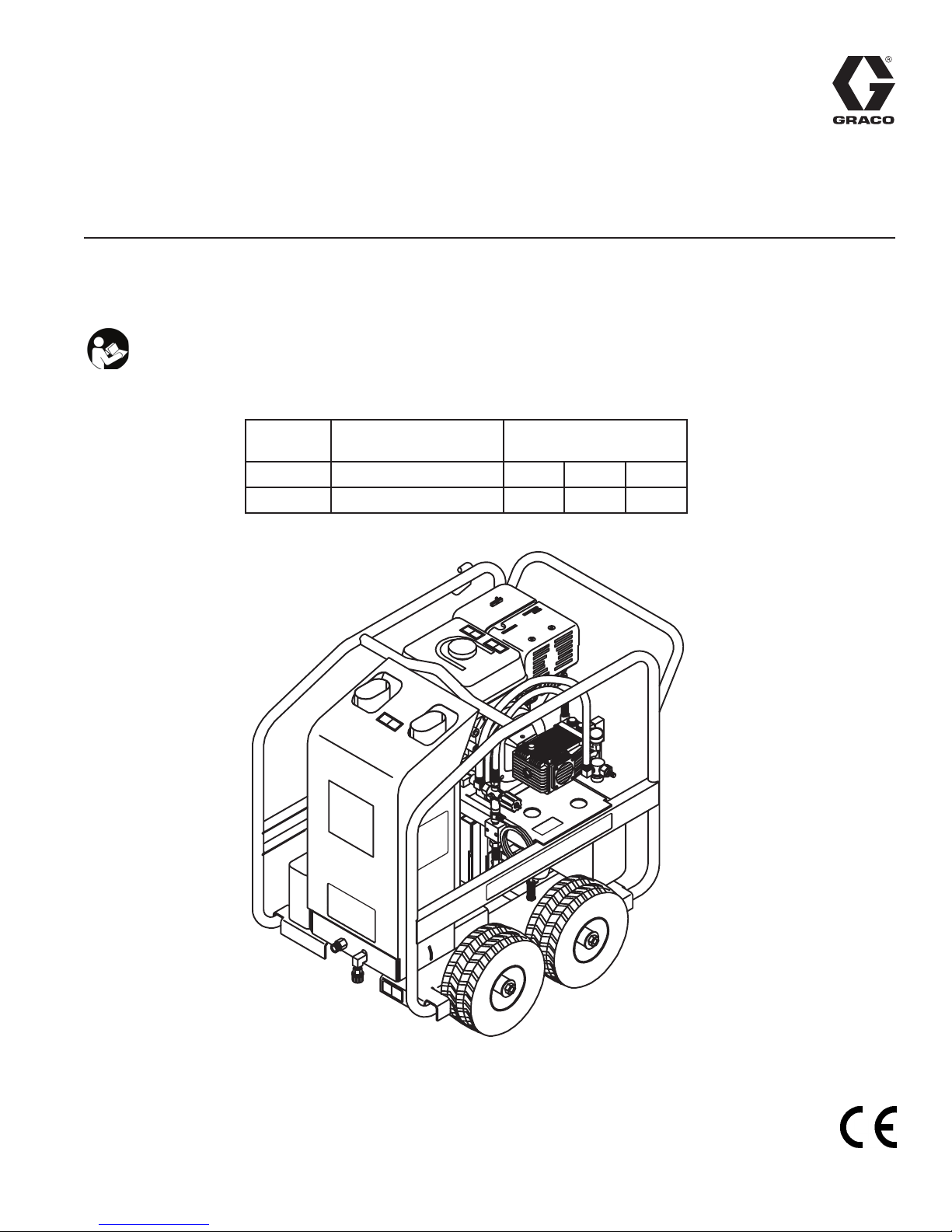
AquaMax Hot Water Pressure Washer 3A0784C
EN
-For high pressure, hot water cleaning-
-For outdoor use only-
IMPORTANT SAFETY INSTRUCTIONS
Read all warnings and instructions in this manual.
SAVE THESE INSTRUCTIONS.
Model Horse Power and
Motor Brand
3540GHW
390 cc Honda 3500 24.13 241.3
Maximum Working
Pressure
PSI MPa bar
PROVEN Q U A L I T Y. LEADI N G TECHN O L O G Y.
37-1113E 012213

CONTENTS
CONFORME À LA NORME NMB-002 DU CANADA.
Important ........................................................................ 3
Spray Precautions ......................................................... 3
Fire & Ventilation Precautions ...................................... 4
Carbon Monoxide Hazard ............................................. 4
Detergent Cleaning Precautions .................................. 4
Burn Hazard ................................................................... 4
Miscellaneous Safety Precautions ............................... 5
Adjustment Precautions ............................................... 5
Personal Protective Equipment ................................... 5
Component Identication ............................................. 6
Installation & Preparation instructions ........................ 7
Attire ................................................................................ 7
Setup ............................................................................... 7
Engine/burner Fuel Tank .................................................. 8
Nozzle Review ................................................................. 8
Dual Lance Assembly With Adjustable Pressure............. 9
Dual Lance Connection ................................................... 9
Water Supply ................................................................. 10
Unloader ........................................................................ 11
Thermal Relief Valve ...................................................... 11
Pre-start Inspection Procedures ................................... 11
Operating Instructions ................................................ 12
Priming The Pump ......................................................... 12
Direct Feed: ................................................................... 12
Start-up/cold Water Operation ...................................... 13
Start-up/hot Water Operation ........................................ 14
Cleaning With Detergents .............................................. 15
Shutdown ...................................................................... 15
Storage & Maintenance instructions ......................... 16
Engine ............................................................................ 16
Pump ............................................................................. 16
Nozzles .......................................................................... 16
Couplers ........................................................................ 16
Fuel Water Separator .................................................... 16
Burner Air Adjustment ................................................... 16
Leaks ............................................................................. 16
Winterizing ..................................................................... 17
Troubleshooting ........................................................... 18
Pump Service: 3540 GHW Model Pressure Washers 20
Valves ............................................................................ 20
Pumping Section ........................................................... 20
Servicing Plungers ......................................................... 20
Servicing V-packings ..................................................... 20
Notes ............................................................................ 21
Pressure Washer - Parts ............................................. 22
262314- Model 3540 GHW ........................................... 22
Engine/Pump Assembly - Parts ................................. 24
Item 17 (For Use With Model 3540 GHW) ..................... 24
Pump Assembly - Parts .............................................. 26
16E609 (For Use With Model 3540 GHW) ..................... 26
Unloader/Manifold Assembly - Parts ........................ 28
Item 8 (For Use With Model 3540 GHW) ....................... 28
Heat Exchanger/EMF Assembly - Parts .................... 30
Item 31 (For Use With Model 3540 GHW) ..................... 30
Bracket/Electrical Box Assembly - Parts .................. 32
Item 28 (For Use With Model 3540 GHW) ..................... 32
Decal Placement - Parts ............................................. 35
262314 - Model 3540 GHW .......................................... 35
Notes ............................................................................ 36
Technical Data ............................................................. 37
Graco Standard Warranty ........................................... 38
THIS SPARK IGNITION SYSTEM COMPLIES WITH
CANADIAN ICES-002.
CE SYSTÈME D’ALLUMAGE PAR ÈTINCELLE EST
2
The following warnings are for the setup, use, grounding, maintenance, and repair of this equipment. The
exclamation point symbol alerts you to a general warning and the hazard symbols refer to procedure-spe-
cic risks. When these symbols appear in the body of this manual, refer back to these Warnings. Productspecic hazard symbols and warnings not covered in this section may appear throughout the body of this
manual where applicable.
WARNING
IMPORTANT
The engine exhaust from this product contains chemicals known to the State of California to cause cancer,
birth defects or other reproductive harm.
This product contains one or more chemicals known to the State of California to cause cancer and birth
defects or other reproductive harm.
The following is required by California State law, Section 4442 of the California Public Resources Code.
Other states may have similar laws. Federal laws apply on federal lands.
• A spark arrester must be added to the mufer of this engine if it is to be used on any forest covered,
brush covered or grass covered unimproved land. The arrester must be maintained in effective working
order by the operator.
• See your engine or equipment dealer for spark arrester mufer options.
SPRAY PRECAUTIONS
Risk of injection or severe cutting injury. If an accident does occur and the spray appears to have penetrated the skin, seek emergency medical care. Do not treat as a simple cut. If you are using cleaning
agents, be prepared to tell a physician exactly what kind.
• Keep clear of nozzle.
• Do not direct discharge stream at persons or pets.
• Only trained operators should use this product. When operating this unit, basic precautions should
always be observed.
• Keep away from the spray. Because of the high pressure and velocity of the spray, uids can penetrate
the skin, causing serious injury.
• Never point the gun at yourself or anyone else. Never put your hand, ngers or body directly over the
spray nozzle. Always keep operating area clear of all persons. Use extreme caution when operating
near children.
• Always wear protective goggles when operating the unit to shield the eyes from ying debris and detergents. Protective equipment such as rubber suits gloves and respirators are advisable, especially when
using cleaning detergents. Use extreme caution when operating near children.
• Stay alert-watch what you are doing. Do not operate the unit when fatigued or under the inuence of
alcohol or drugs.
• Never squeeze the trigger unless securely braced. The thrust from the water traveling through the
nozzle may be powerful enough to cause the operator to lose balance if unprepared. Do not overreach
or stand on unstable support. Wet surfaces can be slippery, wear protective foot gear and keep good
footing and balance at all times. Never trigger the gun while on a ladder or roof.
• Caution should be used when directing spray toward fragile materials such as glass. Shattering could
result in serious injury.
• Always hold on rmly to the gun/wand assembly when starting and operating the unit. Failure to do so
can cause the wand to fall and whip dangerously. Never operate the gun with the trigger wired in the open
position. To prevent accidental discharge, the trigger gun should be securely locked when not in use.
3
WARNING
• Do not direct spray on or into electrical installations of any kind! This includes electrical outlets, light
bulbs, fuse boxes, transformers, etc. Severe electrical shock may occur.
• Even after you shut off the unit, there is high pressure water left in the pump, hose and gun until you
release it by triggering the gun. Before removing the spray nozzle or servicing the unit, always shut off
the unit and trigger the gun to release trapped pressure.
FIRE & VENTILATION PRECAUTIONS
• This unit was designed for outdoor use only. Never operate this unit in an enclosed area. Always make
certain there is adequate air (oxygen) for combustion as well as ventilation to prevent the presence of
poisonous carbon monoxide gases. Beware of poorly ventilated areas or exhaust fans which can cause
inadequate combustion or engine overheating.
• Never operate this unit in the presence of ammable vapors or combustible dust, gases or other combustible materials. (A spark may cause an explosion or re.) When servicing this machine, be especially careful to properly dispose of any ammable materials. Do not spray ammable liquids.
• Do not smoke while lling engine fuel tank
• Never ll the engine fuel tank while the unit is running or hot. Allow the engine to cool two minutes
before refueling.
• Do not refuel indoors or in a poorly ventilated area.
• Always refuel slowly to avoid the possibility of spilled fuel which may cause a risk of re.
• Do not operate the unit if gasoline is spilled. Wipe unit clean and move the unit away from the spill.
Avoid creating any ignition until the gasoline has evaporated.
• Do not store the unit near an open ame or any equipment such as a stove, furnace, water heater, etc.,
which utilizes a pilot light or devices which can create a spark.
• This pressure washer has a safety relief device which should never be altered, modied, removed or made
inoperative. If the device fails, replace immediately with only genuine manufacturer replacement part.
CARBON MONOXIDE HAZARD
Exhaust contains poisonous carbon monoxide, which is colorless and odorless. Breathing carbon monoxide can cause death.
• Do not operate in an enclosed area.
DETERGENT CLEANING PRECAUTIONS
• Do not use solvents or highly corrosive detergents or acid type cleaners with this pressure washer.
• Know your detergent. Be prepared to tell a physician exactly what you are using in the event of an
emergency. Read the Material Safety Data Sheet (MSDS) provided with your detergent and all detergent labels. Follow all appropriate instructions regarding preparation use, safety and transportation.
Keep all detergents out of the reach of children.
• Do not use this pressure washer to dispense hazardous detergents.
• Do not alter the detergent injection feature in any manner not prescribed in this manual. Use only genu-
ine replacement parts for necessary repairs.
BURN HAZARD
Equipment surfaces and uid that’s heated can become very hot during operation. To avoid severe burns:
• Do not touch hot uid or equipment.
4
WARNING
MISCELLANEOUS SAFETY PRECAUTIONS
• Never allow children or adolescents to operate this unit.
• Read and follow all handling, operations, maintenance and safety instructions listed in this manual and
the engine operator’s manual that accompanies this unit, and provide such information to anyone who
will be operating this unit.
• In freezing temperatures, the unit must always be warm enough to ensure there is no ice formation in
the pump. Do not start this unit if it has been transported in an open or under heated vehicle without
rst allowing the pump to thaw.
• When connecting the water inlet to the water supply mains, local regulations of your water company
must be observed. In some areas the unit must not be connected directly to the public drinking water
supply. This is to ensure that there is no feedback of the detergents into the water supply. (Direct con-
nection is permitted if a back ow preventer is installed.)
• Do not allow any part of your body or the high pressure hose to make contact with the mufer. Avoid
dragging the hose over an abrasive surface such as cement. This causes wear and eventual rupturing.
• High pressure hoses should be inspected daily for signs of wear. If evidence of failure exists, promptly
replace all suspect hoses to prevent the possibility of injury from the high pressure spray. If a hose or
tting is leaking , never place your hand directly on the leak.
• Do not operate the unit without all protective covers in place.
• Never run the unit with the governor disconnected or operate at excessive speeds.
• To reduce the risk of injury, maintain a safe distance for persons while operating this unit. Close super-
vision is necessary when operating the unit near children.
• Do not leave pressurized unit unattended. Shut off the unit and release trapped pressure before leaving.
• Do not move the unit by pulling on the hose.
ADJUSTMENT PRECAUTIONS
• Never alter or modify the equipment, be sure any accessory items and system components being used
will withstand the pressure developed. Use only genuine parts for repair of your pressure washer. Failure to do so can cause hazardous operating conditions and will void warranty.
• Never make adjustments to the machinery while it is connected to the engine without rst removing the
ignition cable from spark plug. Turning the machinery over by hand during adjustment or cleaning might
start the engine and machinery with it, causing serious injury to the operator.
• Know how to stop the pressure washer and bleed pressures quickly. Be thoroughly familiar with controls.
• Before servicing the unit; turn the unit off, relieve the water pressure, and allow the unit to cool down.
Do not make repairs while unit is running. Service in a clean, dry, at area. Block the wheels to prevent
the unit from moving.
• Follow the maintenance instructions specied in this manual.
PERSONAL PROTECTIVE EQUIPMENT
You must wear appropriate protective equipment when operating, servicing, or when in the operating area
of the equipment to help protect you from serious injury, including eye injury, hearing loss, inhalation of
toxic fumes, and burns. This equipment includes but is not limited to:
• Protective eye wear, and hearing protection.
• Respirators, protective clothing, and gloves as recommended by the detergent manufacturer.
5
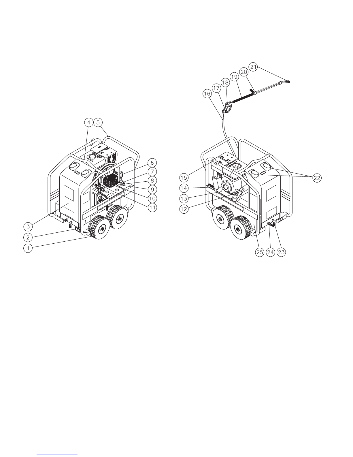
Component Identication
Item Description
1 Pnuematic Wheels
2 Protective Roll Cage
3 Protective Cover
4 Center Balanced Lift Eye
5 Convenient Push/Pull Handle
6 Pressure Gauge
7 Water Inlet
8 Water Inlet Quick Connect Adapter
9 Water Strainer
10 High Pressure Pump
11 Beltguard
12 Burner On/Off Switch
6
Item Description
13 Engine Gasoline Tank
14 Nozzle Holder
15 Wand Holder
16 High Pressure Hose
17 Trigger Safety Lock
18 Trigger Gun
19 Insulated Lance
20 Adjustable Pressure Dual Lance
21 Nozzle
22 Heat Exchanger Exhaust
23 Coil Drain Assy
24 High Pressure Outlet
25 Burner Fuel Tank

INSTALLATION & PREPARATION
INSTRUCTIONS
Attire
Proper attire is essential to your safety. It is advised to
utilize whatever means necessary to protect eyes, ears,
and skin. Additional safety attire (such as respiratory
mask) may be required when using detergent cleaning
agents with this washer.
Setup
This unit should only be placed on a level surface to ensure proper lubrication for the engine and water pump
while operating.
Do not use unit in an area:
• with insufcient ventilation.
• where there is evidence of oil or gas leaks.
• where ammable gas vapors may be present.
Do not allow the unit to be exposed to rain, snow or
freezing temperatures. If any part of the unit becomes
frozen, excessive pressure may build up in the unit
which could cause it to burst resulting in possible serious injury to the operator or bystanders.
Pump oil level should be checked before each use.
Check the oil level indicator on the pump crankcase.
Make certain the oil is in the center of the oil sight glass.
If the level appears to be low, ll with recommended
pump oil.
This unit has multiple ignition sources that could cause
an explosion or re.
Be certain to block the wheels to prevent the unit from
moving while operating.
7
INSTALLATION & PREPARATION
INSTRUCTIONS
Engine/Burner Fuel Tank
Review “Fire & Ventilation Precautions” pg. 4, before
fueling.
Locate the Safety Decals on your unit and heed their
warnings.
Gasoline Engines: When lling tank, gasoline fuel
should be a minimum of 85 octane. Do Not mix oil with
gasoline. Gasoline fuel should be purchased in quantities that maybe be used within 30 days. Use of clean
fresh lead-free gasoline is recommended. Leaded gasoline may be used if lead-free is unavailable. Do Not use
gasoline containing methanol or alcohol.
Burner Fuel: When lling tank, use No. 1 or No. 2 fuel
oil/diesel or kerosene.
Check the engine oil level before starting the engine.
(See engine manual.)
Refer to the engine manual supplied with this unit for
proper engine adjustment procedures.
Review the engine manual accompanying this pressure
washer for correct engine start-up and maintenance
procedures.
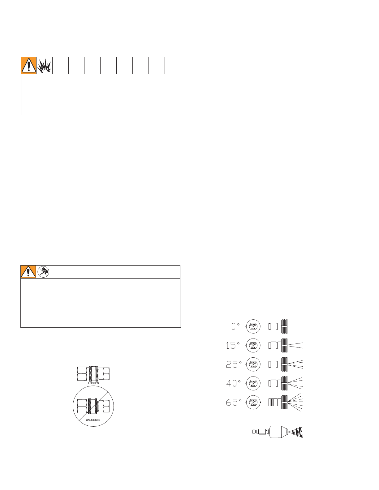
Nozzle Review
Various nozzles may be quick-connected into the end
of the wand to change the spray pattern or use the
detergent feature. When using Quick Connects (Q.C.),
be certain the connection is securely locked. If not,
the high pressure water may shoot the nozzle from the
wand, causing severe injury or serious damage.
The 0° nozzle (RED): This is a blasting nozzle. It delivers a very concentrated stream of water. Be cautious
when using the straight narrow stream. It is not recommended for use on painted or wood surfaces, or items
attached with adhesive backings. Uses: Removing
weeds from sidewalk cracks, stubborn stains from concrete, masonry, aluminum and steel, caked mud from
equipment, and cleaning lawn mower undersides.
The 15° nozzle (YELLOW): This is a chiseling nozzle.
The spray should be directed at a 45° angle to the
surface and used like a scraper to remove paint, grease
and dirt. Uses: Surface preparation (removing mildew
stains and paint chips).
The 25° nozzle (GREEN): This is a ushing nozzle.
This pattern is best suited for ushing dirt, mud, and
grime. Uses: Wet sweeping leaves from walks, curbs
and driveways, cleaning stable oors, washing swimming pool bottoms, degreasing engines.
The 40° nozzle (WHITE): This is a wash nozzle. This
wide spray pattern disperses the water pressure over a
large area and is recommended for moderate washing.
Uses: Washing down aluminum siding, cleaning windows, washing vehicles, spraying sidewalks, driveways
and patios.
The 65° nozzle (BRASS 1/4” NPT): This is a low pressure detergent application nozzle. This broad spray
pattern distributes solution over vast areas under low
pressure. Uses: Detergent application, misting or rinsing. Factory Installed.
The Rotoblast nozzle: Rotating nozzles increase your
cleaning power and decrease your cleaning time.
They offer 0° spray impact with 25° coverage. Nozzles
include lter with quick connect and offer heavy-duty
components for long life and reliability. Uses: Sidewalks,
driveways, track vehicles, muddy areas, old peeling
paints and concrete surfaces.
To determine spray fan, refer to the actual number
stamped on the nozzle. The rst two digits indicate the
spray fan in degrees, i.e.; 0=0°, 15=15°, 25=25°, 40 =
40°, 65=detergent/low pressure.
8
INSTALLATION & PREPARATION
INSTRUCTIONS
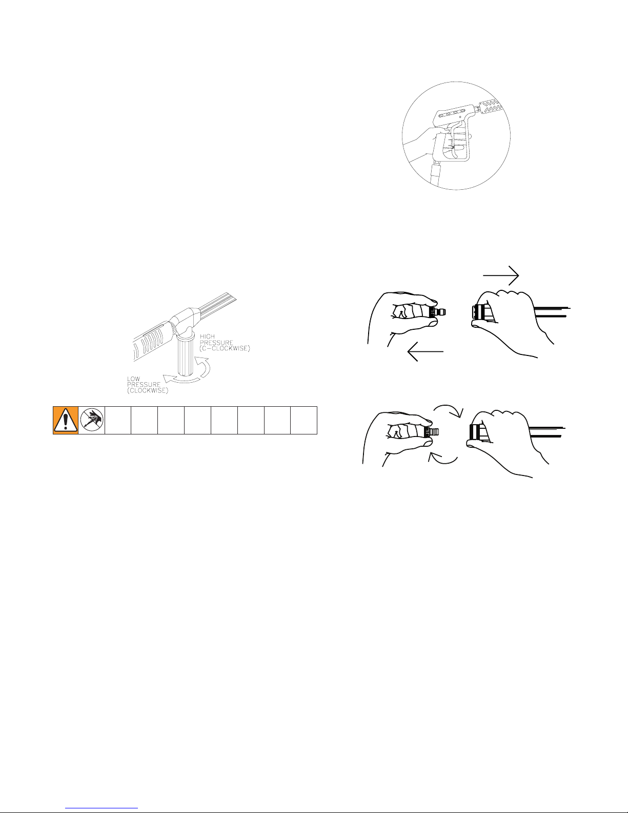
Dual Lance Assembly with Adjustable Pressure
This unit features a Dual Lance Assembly with adjustable pressure which allows the user to select a high or
low pressure “fan” spray. Simply rotate the adjustable
grip on the dual lance to achieve the desired pressure
selection.
1. Selection of high pressure can be achieved by turning
the adjustable grip on the Dual Lance assembly
counterclockwise as shown in the gure below.
2. Selection of low pressure detergent application can
be achieved by turning the adjustable grip on the Dual
Lance clockwise as shown in the gure below. Once
the pressure is low enough, the detergent injector
on the pressure washer will draw detergent into the
system. A water/detergent mixture exits from both the
spray nozzle and detergent nozzle.
Nozzle connection
Be certain the trigger gun is locked in the “OFF” position.
The quick connect nozzle assembly should be disconnected from the gun/wand assembly at this time by
retracting the locking ring on the quick-connect tting
to remove the nozzle.
Dual Lance Connection
• Be certain the trigger gun is locked in the "OFF"
position.
• Connect the dual lance assembly to the trigger gun
assembly at this time. Be certain the connection is
securely tightened.
The detergent nozzle is factory installed.
9
INSTALLATION & PREPARATION
INSTRUCTIONS
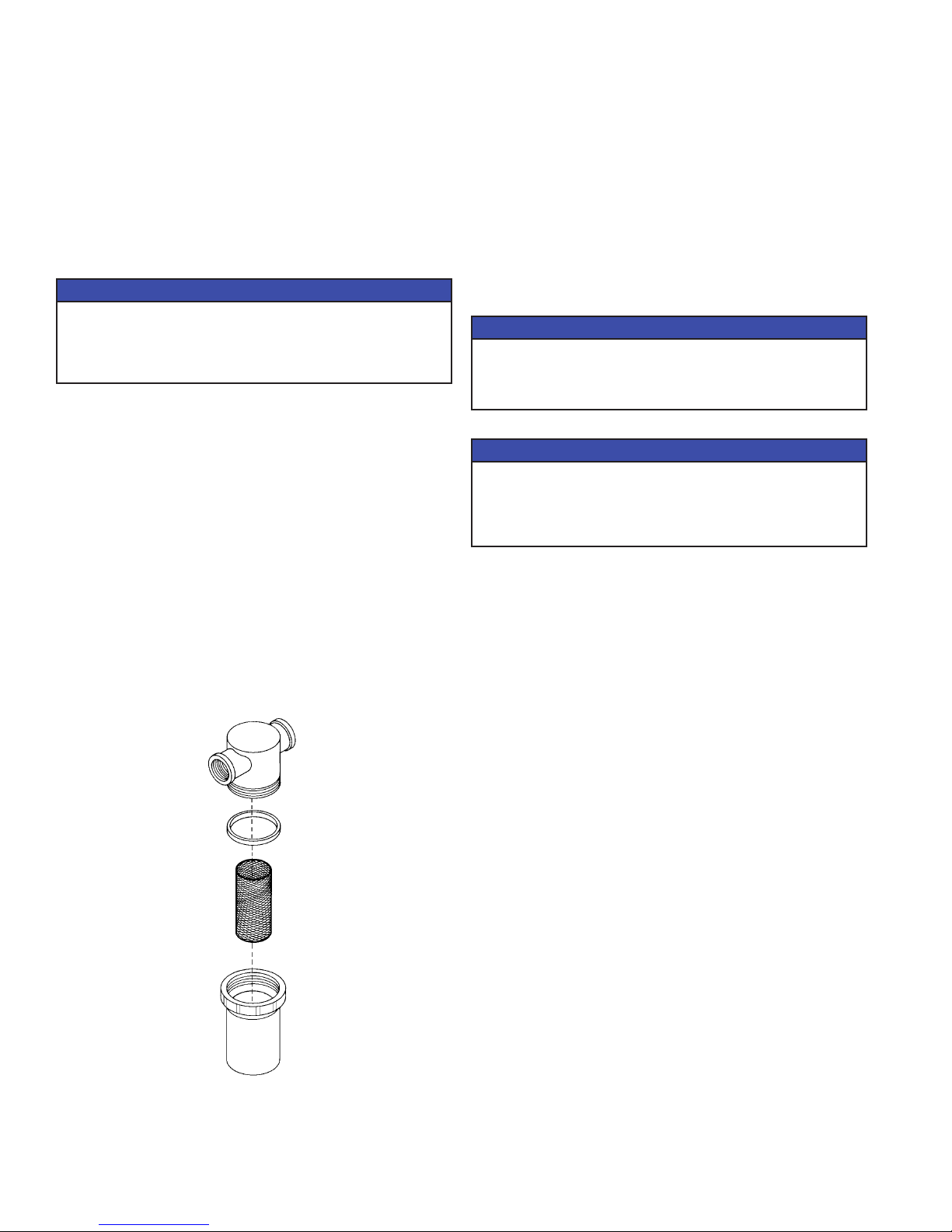
Water Supply
Select a water supply hose which is a quality grade of
garden hose measuring at least 3/4” ID and no longer
than 50 feet.
Check the water inlet strainer to ensure it is clean and
free of any obstructions. Periodic cleaning of the water
strainer will help prevent pump problems.
As a strainer becomes obstructed, it restricts proper
ow of water to the pump. This can result in cavitations which will cause premature failure of pump
packings.
1. Unscrew the strainer cap from the unit.
2. Rem o v e str a in e r scre e n, cl e a n or rep l ace i f
necessary.
Connect the hoses.
1. Connect one end of the water supply hose to the water
inlet of the unit.
2. Connect the other end of the hose to your pressurized
water supply.
NOTICE
Note: If the mineral content of the water in your area is
extremely high, the use of a water softener is recommended to prevent the possibility of excessive scale
buildup inside the heat exchanger coil.
Follow the incoming water requirements listed below:
1. Water pressure must be a minimum of 20 pounds per
square inch (PSI) and a maximum of 125 PSI. (A typical
outdoor faucet will generally supply this PSI if turned
completely “ON”.)
2. Incoming GPM must be approximately one gallon more
than the outgoing GPM stated on the pressure washer
nameplate. (You can check GPM by timing how long
it takes to ll a 5 gallon container.)
Incoming water temperature must not exceed
125°F. Excessive pump damage may result if the
water temperature exceeds this acceptable level.
Damage to the equipment could occur. Never allow
the unit to operate without the incoming water line
attached and the water supply completely turned
on.
NOTICE
NOTICE
Note: When connecting the water inlet to the water
supply mains, local regulations of your water company
must be observed. In some areas, the unit must not be
connected directly to the public drinking water supply.
This is to ensure there is no feedback of detergents
into the water supply. (Direct connection is permitted
if the backow preventer is installed. Check with local
authorities for approval.)
10

INSTALLATION & PREPARATION
INSTRUCTIONS
Unloader
Adjustable
The unloader valve on your machine is equipped with
an adjustment knob to adjust the pressure. Should
less pressure be required, simply turn the adjustment
knob counterclockwise. To set back to maximum, turn
adjustment knob completely clockwise. Do not overtighten.
Do not overtighten the unloader. Breakage could
result in immediate loss of water pressure and
costly repairs.
NOTICE
A “thermal relief valve” has been added to this unit to
protect the pump. It may begin to open and release
water if the water temperature in the pump has exceeded 140°F. This will allow fresh, cool water to enter
the system.
Pre-Start Inspection Procedures
Before starting the unit, perform the following procedures:
1. Check the oil level in the pump and engine.
2. Inspect the water inlet strainer. Clean or replace if
necessary. See “Water Supply” pg. 9.
3. Check all hose connections to ensure they are securely
tightened. See “Water Supply” pg. 9.
Inspect for system fuel leaks. If a fuel leak is found, do
not start unit. See “Fire & Ventilation Precautions” pg.
4. Be sure that all damaged parts are replaced and that
the mechanical problems are corrected prior to operation of the unit. If you require service, contact Graco
Customer Service.
Thermal Relief Valve
To ensure the water temperature does not exceed
acceptable levels, never allow the pressure washer to
operate in the bypass mode (with the unit running and
the trigger gun closed) for more than three minutes.
Inspect high pressure hoses for kinking, cuts and leaks.
If a cut or leak is found, do not use hose. Replace hose
before starting unit. See “Miscellaneous Safety Precautions” pg. 5. Be sure that all damaged parts are replaced and that the mechanical problems are corrected
prior to operation of the unit. If you require service,
contact Graco Customer Service.
11

OPERATING INSTRUCTIONS
Priming the Pump
It is essential to prime the pump and ush the unit each
time the water supply has been disconnected from the
unit OR whenever the unit has set for any period of
time. This unit has a steel coil which, after setting, will
cause the water remaining in the coil from the previous
usage to turn brown or black. This contaminated water
must be ushed from the system before start-up. This
procedure should be performed without the high pressure hose, gun and dual lance assembly installed.
Direct Feed:
1. Turn on the water supply.
2. Low pressure water will begin owing from the water
outlet. This allows the unit to prime and purge any air
from the system. The unit is primed when water ow
is uninterrupted by air.
3. Once the unit is primed, turn off the water supply and
connect the high pressure discharge hose to the water
outlet of the unit. (Note: The trigger gun and dual
lance assembly should already be connected to the
high pressure discharge hose at this time.)
4. Turn on the water supply.
Be certain the nozzle is not connected to the unit
while priming the pump. Priming allows mineral deposits to be released from the system which would
obstruct or damage the nozzle assembly resulting in
costly repairs.
NOTICE
12
 Loading...