

Page 1

WARNING
WARNING
Repair Kit Instructions
Control and Pump Kits for SaniSpray
™
HP
65 Portable Hopper Sprayer
Use these instructions when replacing the control board or pump components for the
SaniSpray HP 65 Portable Hopper Sprayer.
Important Safety Instructions
Read all warnings and instructions in this manual and in Operations manual before using
the equipment. Be familiar with the controls and the proper usage of the equipment. Save
all instructions.
Includes:
Control Board Replacement, page 8
Pump Cartridge Replacement, page 10
Pump Inlet Valve Replacement, page 11
Prime Valve and Knob Replacement, page 11
Pressure Control Replacement, page 13
ELECTRIC SHOCK HAZARD: To avoid
serious injury, turn off and disconnect
power cord before servicing the
equipment.
Pressure Relief Procedure
Before servicing the sprayer, pump pressure
must be relieved.
SKIN INJECTION HAZARD: This
equipment stays pressurized until
pressure is manually relieved. To help
prevent serious injury from pressurized
fluid, such as skin injection or splashing
fluid, follow the Pressure Relief
Procedure whenever sprayer is stopped
and before sprayer is cleaned or
checked, and before equipment is
serviced.
1. Turn ON/OFF switch to the OFF position.
25T416, 25T417
25T418
25T403
25T415
25T402
2. Engage the trigger lock. Always engage
the trigger lock when sprayer is stopped to
prevent the gun from being triggered
accidentally.
3. Turn Pressure Control Knob to the lowest
setting.
4. Put drain tube into a pail and turn
Prime/Spray Valve to PRIME position to
relieve pressure.
Hold a metal part of the Spray Gun firmly to a
5.
grounded metal pail. Point Spray Gun into
pail. Disengage the Trigger Lock and trigger
the Spray Gun to relieve pressure
6. Engage the trigger lock.
7. If you suspect the spray tip or hose is
clogged or that pressure had not been fully
relieved:
a. VERY SLOWLY loosen the spray tip
guard retaining nut or the airless
hose end coupling to relieve pressure
gradually.
b. Loosen the nut or coupling
completely
c. Clear airless hose or spray tip
obstruction.
3A7936A
.
EN
Use only genuine Graco replacement parts.
The use of non-Graco replacement parts may void warranty.
Page 2
Torque to 110-120 in-lb
(12.5-13.6 N•m)
Torque to 30-36 in-lb
(3.4-4.0 N•m)
1
2
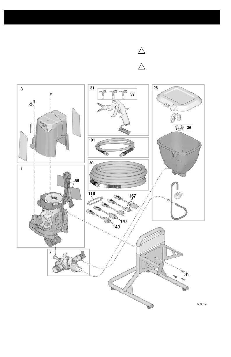
Parts - SaniSpray HP 65 (Quick Repair)
2 3A7936A
Page 3
Parts List - SaniSpray HP 65 (Quick Repair)
Ref. Sprayer Model Part Description Qty.
25R972, 25R962 25R921 KIT, motor, drive, HP65, 120V, includes 56
1
25R948, 25R954 25T292 KIT, motor, drive, 230V, multi, includes 56
7 All 25R920 KIT, pump 1
8 All 25R922 KIT, enclosure 1
26 All 25R923 KIT, hopper 1
25R792 25R874 GUN, SaniSpray, HP, NA
31†
25R954, 25R962 25T290 GUN, SaniSpray, HP, AP
LP617 TIP, LP617
32 All
LP621 TIP, LP621
36 All 112133 SCREEN, hopper 1
56 All 25T410 KIT, warning labels, cord 1
CARD, medical alert (not shown)
222385 English, Spanish, French
17F690 Dutch, German, Italian
60 All
98 All 25T282 EXTENSION, 15 in. (not shown) 1
99* All 25R872 TIPSEAL, 5-pack (not shown) 1
101 All 25C828 HOSE, 1/8 in. x 4-1/2 ft. 1
118 25R948, 25R954 195551 PLUG, retaining 1
144 25R962 244285 CORDSET, Japan (not shown) 1
146 25R954 17N232 CORDSET, India (not shown) 1
147 25R948, 25R954 242001 CORDSET, EU Schuko 1
149 25R954 242005 CORDSET, ANZ 1
157 25R948 287121 CORDSET, Italy, Denmark, Switzerland 1
158 25R948 17J242 CORDSET, UK (not shown) 1
Motor/Drive Kit 25R921 does not include cordset adapter for Japan. Cordset adapter must
be ordered separate (see Ref. 144). Control Kit 25T292 does not include cordset adapter.
Cordset adapter must be ordered separate (see Ref. 146-158).
* Two extra TipSeals (polymer spray tip seals) are included with the sprayer. For disinfectant
applications, use TipSeal (polymer spray tip seal) instead of the OneSeal (metal seal) that
is included with the replacement spray tips.
† SaniSpray HP Gun includes LP619 Spray Tip.
Replacement safety labels, tags, and cards are available at no cost.
17A134 English, Chinese, Korean
17R476 English, Spanish, Portuguese (Brazil)
26A997 English, Indonesian, Hindi
26A998 English, Chinese, Japanese
125R946 25T291 KIT, motor, drive, 230V, CEE, includes 56
125R946, 25R948 25T289 GUN, SaniSpray, HP, EU
1LP619 † TIP, LP619
1
3A7936A 3
Page 4

Torque to 110-120 in-lb
(12.5-13.6 N•m)
Torque to 30-36 in-lb
(3.4-4.0 N•m)
1
2
5
Parts - SaniSpray HP 65 (Extended Repair)
Ref. Sprayer Model Part Description Qty.
25R792, 25R962 17J173 CORD, power, USA
3
25R948, 25R954 17L301 CORD, power, Multicord
15
15a
39 All 17K336 TUBE, drain, assembly 1
56 All 25T410 KIT, warning labels, cord 1
Replacement safety labels, tags, and cards are available at no cost.
4 3A7936A
25R792, 25R962 25T416 BOARD, control, 100-120V, includes 15a
25R946, 25R948,
25R954
25R792, 25R962 119276 FUSE, 12.5A slow blow, 100-120V
25R946, 25R948,
25R954
25T417 BOARD, control, 220-240V, includes 15a
129882 FUSE, 6.3A slow blow, 220-240V
125R946 17J175 CORD, power, EU Schuko
1
1
Page 5
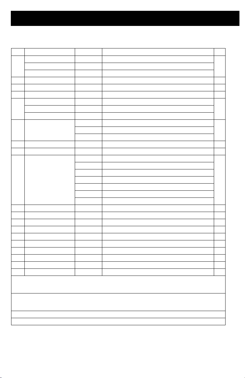
Parts - SaniSpray HP 65 (Pump Repair)
Torque to 140-160 in-lb
(16-18 N•m)
Torque to 270-330 in-lb
(30-37 N•m)
Torque to 30-35 ft-lb
(40-48 N•m)
Torque to 220-250 in-lb
(25-28 N•m)
123
4
Ref. Sprayer Model Part Description Qty.
6 All 25T403 KIT, inlet valve assembly 1
8 All 25T415 KIT, prime valve 1
25 All 25T418 KIT, pump cartridge 1
28 All 25T402 KIT, control, pressure 1
3A7936A 5
Page 6

1
3
ti27463a
2
Motor Shield Removal/Installation
Disassembly
1. Perform Pressure Relief Procedure,
page 1.
2. Disconnect power cord.
Remove Motor Shield
3. Remove two machine screws and motor
shield (8).
Install Motor Shield
1. Install motor shield (8) using the two
screws removed earlier. Make sure the
motor shield slides into the switch bracket.
Be careful not to pinch cable when
installing the motor shield.
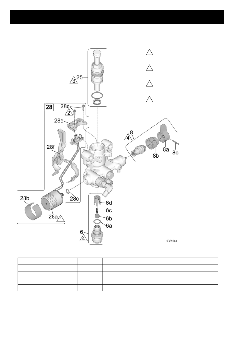
Pump Removal/ Installation
Remove Pump
1. Perform Pressure Relief Procedure,
page 1.
2. Disconnect power cord.
3. Remove the hopper.
4. Remove airless hose, if attached.
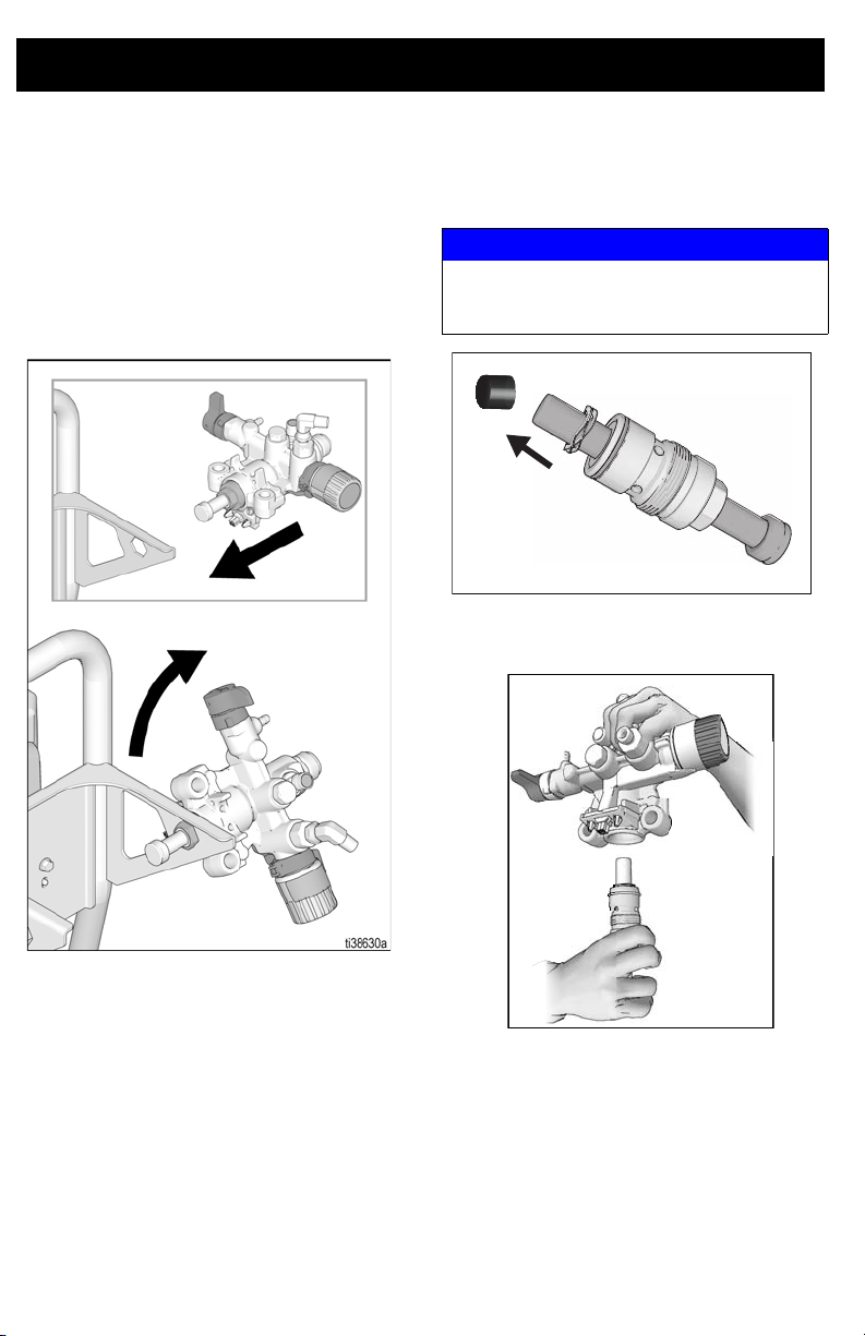
5. Re-position sprayer to access the easy
access door.
Open Easy Access Door
6. Pull tabs on sides of the easy access door
towards you while pushing the entire door
away from the inlet end of the pump.
7. Now lift the easy access door so it swivels
out of the way.
6 3A7936A
Page 7
8. Slide pump assembly off the mounting
1
ti27478a
2
3
pins.
2. Move pump displacement rod up or down
until cap is level with the opening in the
yoke.
ti27037a
Install Pump
1. Slide pump assembly onto the mounting
pins.
Close Easy Access Door
3. Swing easy access door closed and push
down to latch into pump.
NOTE: Door must be fully closed and latched
before sprayer will operate.
4. Install hopper and the hoses removed
earlier.
5. Perform Assembly Verification, page 13.
3A7936A 7
Page 8

Control Board Replacement
Refer to Wiring Diagrams, pages 14 and 15.
Note color and location of all wires connected to
the control board before you start the control
board replacement.
Removal
1. Perform Pressure Relief Procedure,
page 1.
2. Disconnect power cord.
3. Remove Motor Shield, page 6.
4. Disconnect pressure switch and motor
connector from control board (15).
5. Disconnect ON/OFF switch and power
cord (3) connectors from control board (15)
leads.
6. Remove screw securing control board (15)
to drive housing.
Installation
1. Carefully slide new control board (15) into
place on the side of the driving housing.
Secure the screw and torque. See Parts -
SaniSpray HP 65 (Extended Repair),
page 4.
8 3A7936A
Page 9

2. Reconnect ON/OFF Switch and power
cord (3) connectors to the control board
(15) leads.
3. Reattach pressure switch and motor
connector to control board (15).
Fuse Replacement
If fuse is blown, check for:
• Pinched or shorted wires
• A defective motor
• A locked or frozen pump
1. Perform Pressure Relief Procedure,
page 1.
2. Disconnect power cord.
3. Remove Motor Shield, page 6.
4. Remove fuse (15a) from control board
(15).
5. Install new fuse (15a) on control board
(15).
6. Install Motor Shield, page 6.
7. Perform Assembly Verification, page 13.
4. Install Motor Shield, page 6.
5. Perform Assembly Verification, page 13.
3A7936A 9
Page 10
ti26947a
ti26954a
Pump Cartridge Replacement
Disassembly
1. Remove Hopper and Pump from sprayer.
See Remove Pump, page 6.
2. Insert hex end of pump into hex tool in the
sprayer frame and turn counterclockwise
to loosen assembly.
Assembly
1. On the new pump cartridge, remove
protective cap from the end of the piston
rod.
NOTICE
Be careful not to lose the packing spring that is
installed on the pump rod. Operation without the
packing spring will cause early pump failure.
2. While holding the pump body upside down,
start threading the new packing assembly
in by hand.
3. Remove entire packing assembly from
pump housing including the packing
spring.
3. Insert hex end of pump into hex tool in the
sprayer frame and tighten. Recommended
torque is 300 in-lb (35 N•m).
4. Install Pump onto sprayer, see page 7.
5. Perform Assembly Verification, page 13.
10 3A7936A
Page 11
Pump Inlet Valve
Prime Valve and Knob
Replacement
See Parts - SaniSpray HP 65 (Pump Repair),
page 5, for pump assembly diagram.
Disassembly
1. Perform Pressure Relief Procedure,
page 1.
2. Disconnect power cord.
3. Remove the hopper.
4. Remove inlet valve fitting (6) from pump
housing and discard. Make certain inlet ball
(6b), spring (6c), and ball guide (6d) are
removed from pump housing.
5. Clean all dried residue from around pump
inlet sealing area in pump housing.
Assembly
1. Assemble ball guide (6d), spring (6c), and
ball (6b) into pump housing (1).
a. The ball guide (6d) is keyed for
proper alignment.
b. Make certain the bump on the ball
guide (6d) is aligned with the slot in
the pump housing. Slide ball guide
(6d) into pump housing.
c. Install spring (6c) over ball stop pin in
the ball guide (6d).
d. Install ball (6b) into ball guide (6d).
2. Make certain o-ring (6a) is installed on inlet
valve housing (6).
3. Thread new inlet valve housing into pump
housing and torque. See Parts -
SaniSpray HP 65 (Pump Repair), page 5,
for torque.
4. Use a pencil or similar object to push on the
ball (6b) through the inlet valve intake to
make sure the ball moves freely.
5. Re-install the hopper.
6. Perform Assembly Verification, page 13.
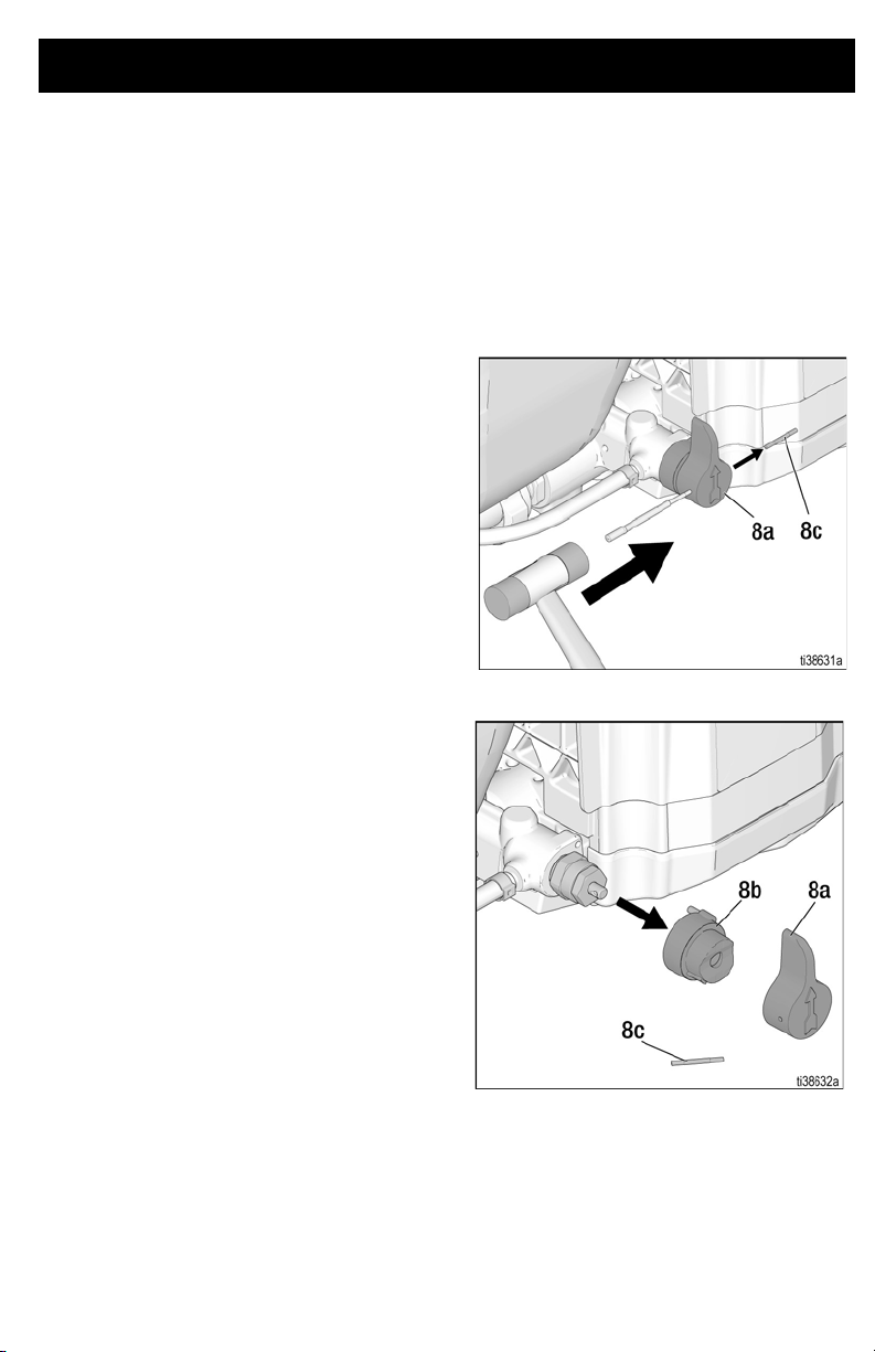
Replacement
1. Perform Pressure Relief Procedure,
page 1.
2. Disconnect power cord.
3. Turn knob (8a) up to SPRAY position.
4. Remove pin (8c) with pin punch and
hammer.
5. Remove knob (8a) and base (8b).
3A7936A 11
Page 12

6. Remove valve stem assembly (8) from
pump housing. Make certain gasket (X)
and seat (Z) do not stay in pump housing.
Assembly
7. Apply sealant (provided in kit) to valve
threads. Install valve stem assembly in
pump manifold and torque. See Parts -
SaniSpray HP 65 (Pump Repair), page 5,
for torque.
8. Install base (8b) on valve, aligning pin (E)
in base (8b) with hole on pump housing.
9. Rotate valve stem with a pin punch until
hole is horizontal.
10. Install knob (8a) over base (8b).
11. Place knob in SPRAY position.
12. Insert end of pin punch through hole in
knob (8a), to make sure knob and valve
stem are aligned.
13. Apply small amount of grease to pin. Install
pin (8c) through hole in knob (8a). Tap pin
through knob with hammer. End of pin will
be flush with knob when correctly installed.
14. Perform Assembly Verification, page 13.
12 3A7936A
Page 13

Pressure Control Replacement
See Parts - SaniSpray HP 65 (Pump Repair),
page 5, for pump assembly diagram.
Disassembly
1. Remove Pump from sprayer, see page 6.
2. Remove wire shield (28f).
• Unsnap the wire shield.
• Remove retaining screw from pump
housing.
• Note wire routing, wires on new
pressure control will be routed the
same way.
• Save wire shield.
3. Remove the two screws (28d) from
electrical connector bracket (28e). Save
the screws.
4. Turn Pressure Control Knob fully
counterclockwise to expose the wrench
flats. Remove pressure control (28a) with
wire and electrical connector bracket
(28e). Verify the o-ring (28c) has been
removed from the pump housing.
Assembly
1. Examine pressure control (28a) to verify
the o-ring (28c) is on the pressure control.
If o-ring is not installed on pressure control,
install o-ring.
2. Apply one or two drops of thread locking
adhesive (included in kit) to threads of
pressure control (28a). Assemble pressure
control (28a) into pump housing and
torque. See Parts - SaniSpray HP 65
(Pump Repair), page 5, for torque.
3. Route wire from pressure control (28a) with
electrical connector bracket (28e) along
pump housing to mounting location.
4. Secure electrical connector bracket (28e)
to pump housing with two screws removed
earlier and torque. See Parts - SaniSpray
HP 65 (Pump Repair), page 5, for torque.
5. Install wire shield (28f).
• Make certain wire is under wire shield
(28f).
• Snap the wire shield around the pump
housing.
• Install retaining screw for wire shield
into pump housing.
6. Turn Pressure Control Knob clockwise as
far as it will go. Apply pressure control label
(28b) to knob. To position label correctly,
see note below:
NOTE: When properly positioned, the function
indicator (fi) and (+) position symbol on the
pressure control label (28b) are aligned.
7. Install Pump onto sprayer, see page 7.
8. Perform Assembly Verification, page 13.
Assembly Verification
After assembly is complete, perform the
following steps to verify proper operation. If
sprayer fails one of the steps, repeat sprayer
repair procedures.
• Rotate Prime/Spray Valve to make sure
it rotates forward to the spray position
and down to the prime pump position.
• Fill cup assembly with water and verify
sprayer primes and sprays. Follow setup
instructions in sprayer operation manual
for proper priming and spraying
procedure.
3A7936A 13
Page 14
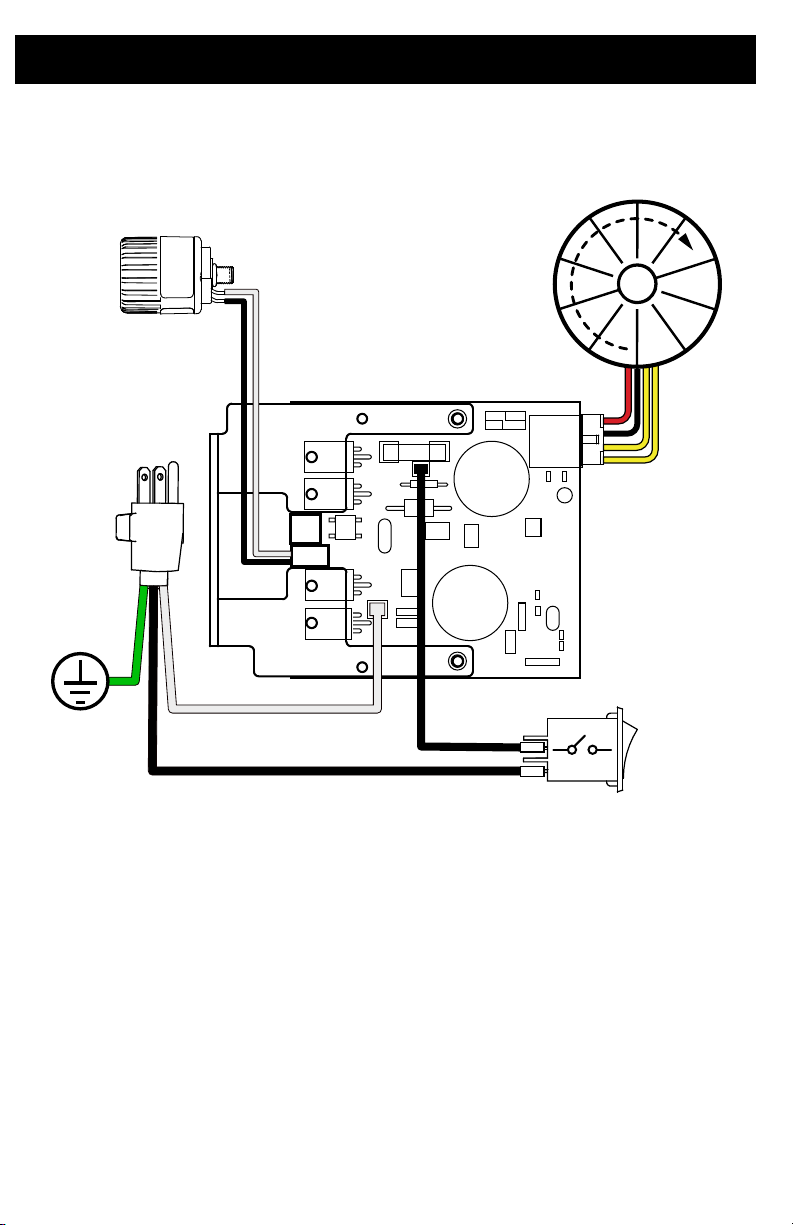
Wiring Diagrams
ti27233a
M
Wiring Diagrams
100-120V
14 3A7936A
Page 15
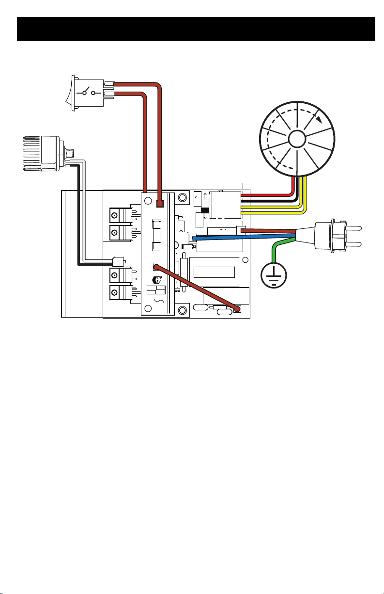
220-240V
ti27485a
M
Wiring Diagrams
3A7936A 15
Page 16

www.graco.com/techsupport
?? ??
Graco Information
For the latest information about Graco products, visit www.graco.com.
For patent information, see www.graco.com/patents.
TO PLACE AN ORDER, contact your Graco distributor or call
distributor.
1-800-690-2894 to identify the nearest
All written and visual data contained in this document reflects the latest product information available at
the time of publication. Graco reserves the right to make changes at any time without notice.
Original instructions. This manual contains English. MM 3A7936
International Offices: Belgium, China, Japan, Korea
GRACO INC. AND SUBSIDIARIES • P.O. BOX 1441 • MINNEAPOLIS MN 55440-1441 • USA
Copyright 2020, Graco Inc. All Graco manufacturing locations are registered to ISO 9001.
Graco Headquarters: Minneapolis
www.graco.com
Revision A, July 2020
 Loading...