

Page 1
Instructions-Parts
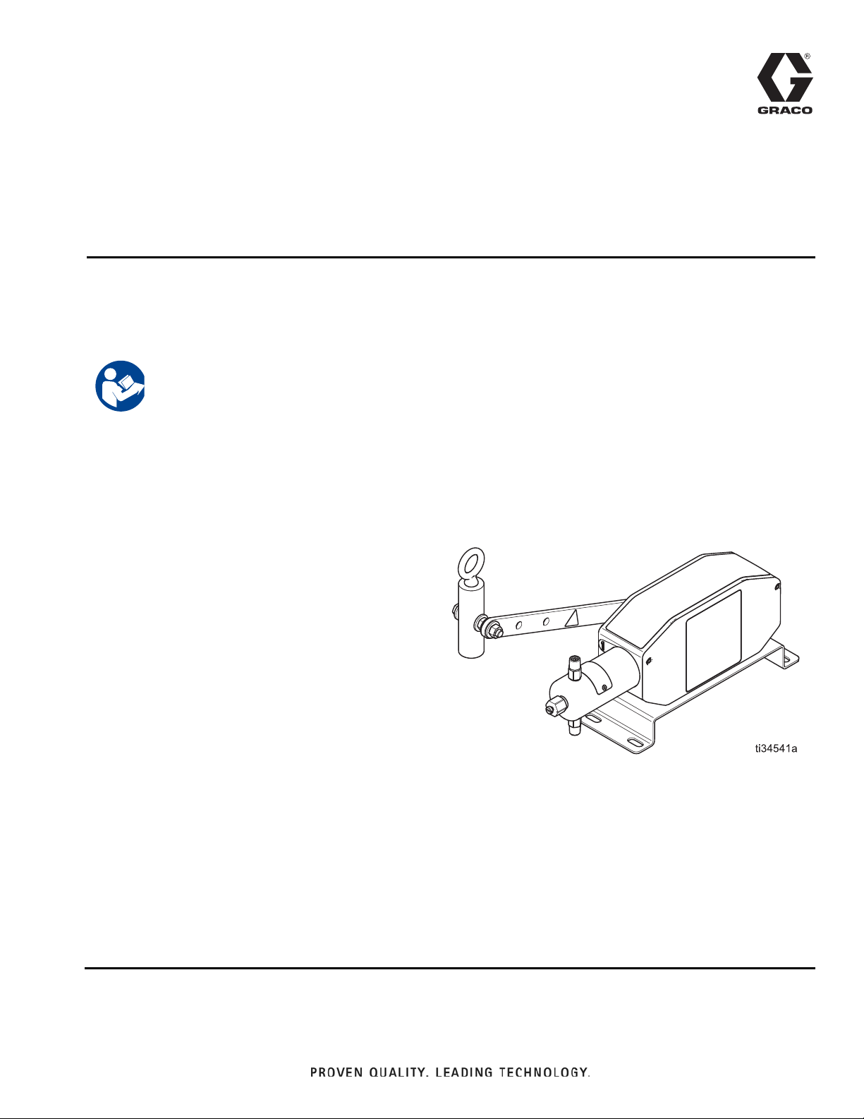
G-Chem Beam
3A6349C
Pump
Lever-driven pump for injecting chemicals at well sites. For professional use only.
See page 3 for model information, including maximum working pressure.
Important Safety Instructions
Read all warnings and instructions in this manual
before using the equipment. Save all instructions.
EN
Page 2

Contents
Models and Approvals . . . . . . . . . . . . . . . . . . . . . . 3
G-Chem Beam Pumps . . . . . . . . . . . . . . . . . . . . 3
Fluid Modules . . . . . . . . . . . . . . . . . . . . . . . . . . . 3
Configuration Number Matrix . . . . . . . . . . . . . . . . . 4
G-Chem Beam Pump Assembly Configuration Code
4
Fluid Module Configuration Code . . . . . . . . . . . . 5
Warnings . . . . . . . . . . . . . . . . . . . . . . . . . . . . . . . . . 6
Installation . . . . . . . . . . . . . . . . . . . . . . . . . . . . . . . . 8
Grounding . . . . . . . . . . . . . . . . . . . . . . . . . . . . . . 8
Accessories . . . . . . . . . . . . . . . . . . . . . . . . . . . . . 8
Flush Before Using Equipment . . . . . . . . . . . . . . 8
Typical Installation . . . . . . . . . . . . . . . . . . . . . . . 8
Pumpjack Connections . . . . . . . . . . . . . . . . . . . 10
Fluid Connections . . . . . . . . . . . . . . . . . . . . . . . 11
Operation . . . . . . . . . . . . . . . . . . . . . . . . . . . . . . . . 12
Pressure Relief Procedure . . . . . . . . . . . . . . . . 12
Flush the Equipment . . . . . . . . . . . . . . . . . . . . . 12
Prime the Pump . . . . . . . . . . . . . . . . . . . . . . . . 13
Calibrate Chemical Dosage . . . . . . . . . . . . . . . 13
Adjust the Pump Stroke . . . . . . . . . . . . . . . . . . 14
Preventive Maintenance Schedule . . . . . . . . . . 17
Tighten Threaded Connections . . . . . . . . . . . . . 17
Tighten Packings . . . . . . . . . . . . . . . . . . . . . . . 17
Storage . . . . . . . . . . . . . . . . . . . . . . . . . . . . . . . 17
Troubleshooting . . . . . . . . . . . . . . . . . . . . . . . . . . 18
Repair . . . . . . . . . . . . . . . . . . . . . . . . . . . . . . . . . . . 19
Pump Repair . . . . . . . . . . . . . . . . . . . . . . . . . . . 19
Parts . . . . . . . . . . . . . . . . . . . . . . . . . . . . . . . . . . . . 21
G-Chem Beam Drive Module . . . . . . . . . . . . . . 21
G-Chem Beam Fluid Module . . . . . . . . . . . . . . 23
Kits and Accessories . . . . . . . . . . . . . . . . . . . . . . 25
G-Chem Beam Pump . . . . . . . . . . . . . . . . . . . . 25
Dimensions . . . . . . . . . . . . . . . . . . . . . . . . . . . . . . 26
G-Chem Beam Pump Dimensions . . . . . . . . . . 26
Technical Specifications . . . . . . . . . . . . . . . . . . . . 27
. . . . . . . . . . . . . . . . . . . . . . . . . . . . . . . . . . . . . . . . . 27
California Proposition 65 . . . . . . . . . . . . . . . . . . . 27
Graco Standard Warranty . . . . . . . . . . . . . . . . . . . 28
2 3A6349C
Page 3
Models and Approvals
G-Chem Beam Pumps
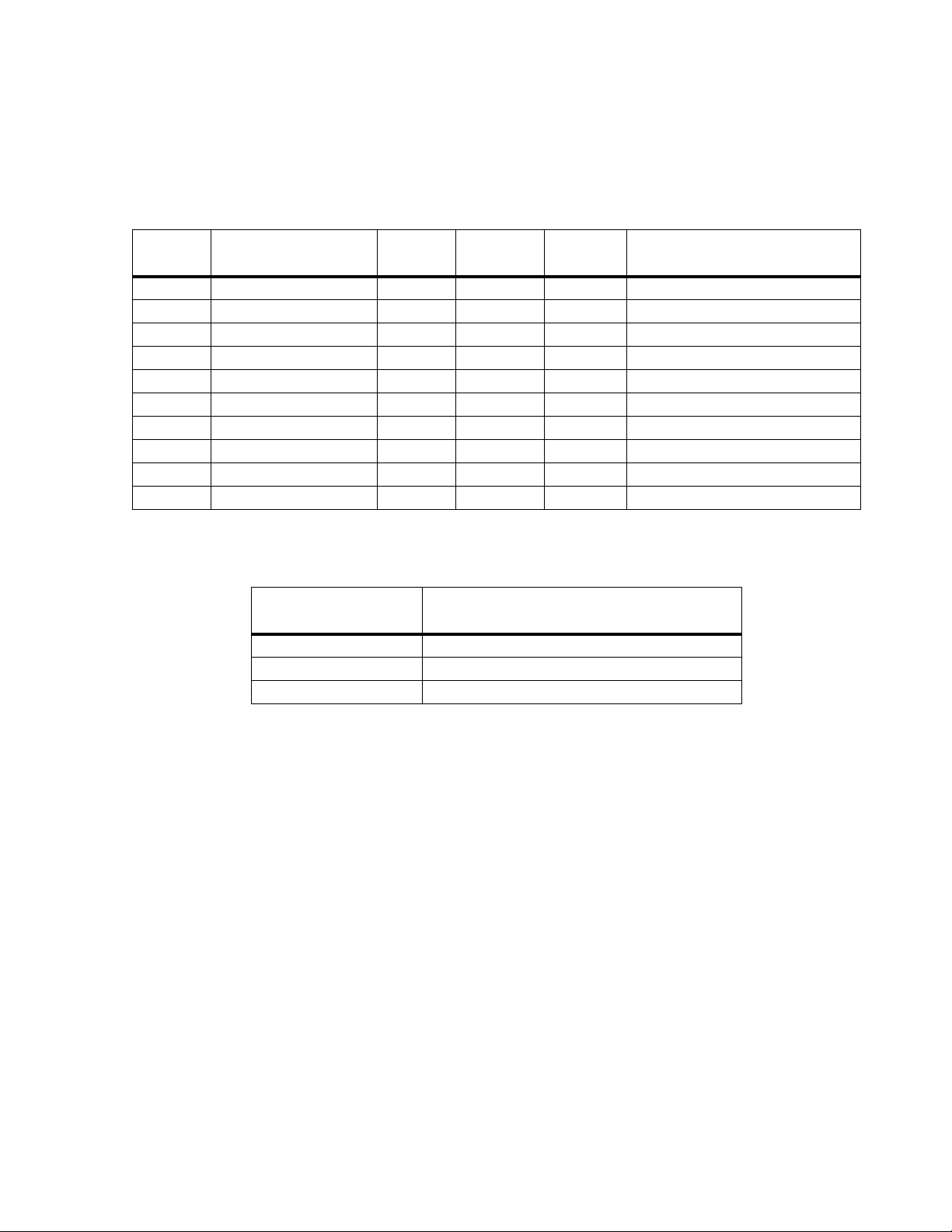
Models and Approvals
Models Configuration Number
A23000 CI-NAO-2XF-000-0 1/4 in. Simplex FKM 2500 (17.2, 172)
A23001 CI-NAO-3XF-000-0 3/8 in. Simplex FKM 1500 (10.3, 103)
A23002 CI-NAO-5XF-000-0 1/2 in. Simplex FKM 800 (5.5, 55)
A23003 CI-NAO-2XG-000-0 1/4 in. Simplex HNBR 2500 (17.2, 172)
A23004 CI-NAO-3XG-000-0 3/8 in. Simplex HNBR 1500 (10.3, 103)
A23005 CI-NAO-5XG-000-0 1/2 in. Simplex HNBR 800 (5.5, 55)
A23006 CI-NAO-2XH-000-0 1/4 in. Simplex TFE/P 2500 (17.2, 172)
A23007 CI-NAO-3XH-000-0 3/8 in. Simplex TFE/P 1500 (10.3, 103)
A23008 CI-NAO-5XH-000-0 1/2 in. Simplex TFE/P 800 (5.5, 55)
A23009 CI-NAO-2XJ-000-0 1/4 in. Simplex PTFE 500 (3.4, 34)
Fluid Modules
Plunger
Size
Plunger Size
1/4 in. 2500 (17.2, 172)
3/8 in. 1500 (10.3, 103)
1/2 in. 800 (5.5, 55)
Number of
Pumps
Maximum Working Pressure
Seal
Material
psi (MPa, bar)
Maximum Working Pressure
psi (MPa, bar)
3A6349C 3
Page 4
Configuration Number Matrix
A23000 CI-2XF-000-0 ########
A 2500(17
)
# ####
Graco Inc., P.O. Box 1441
Mpls, MN 55440 USA
Model Number
Configuration Number
Date Code
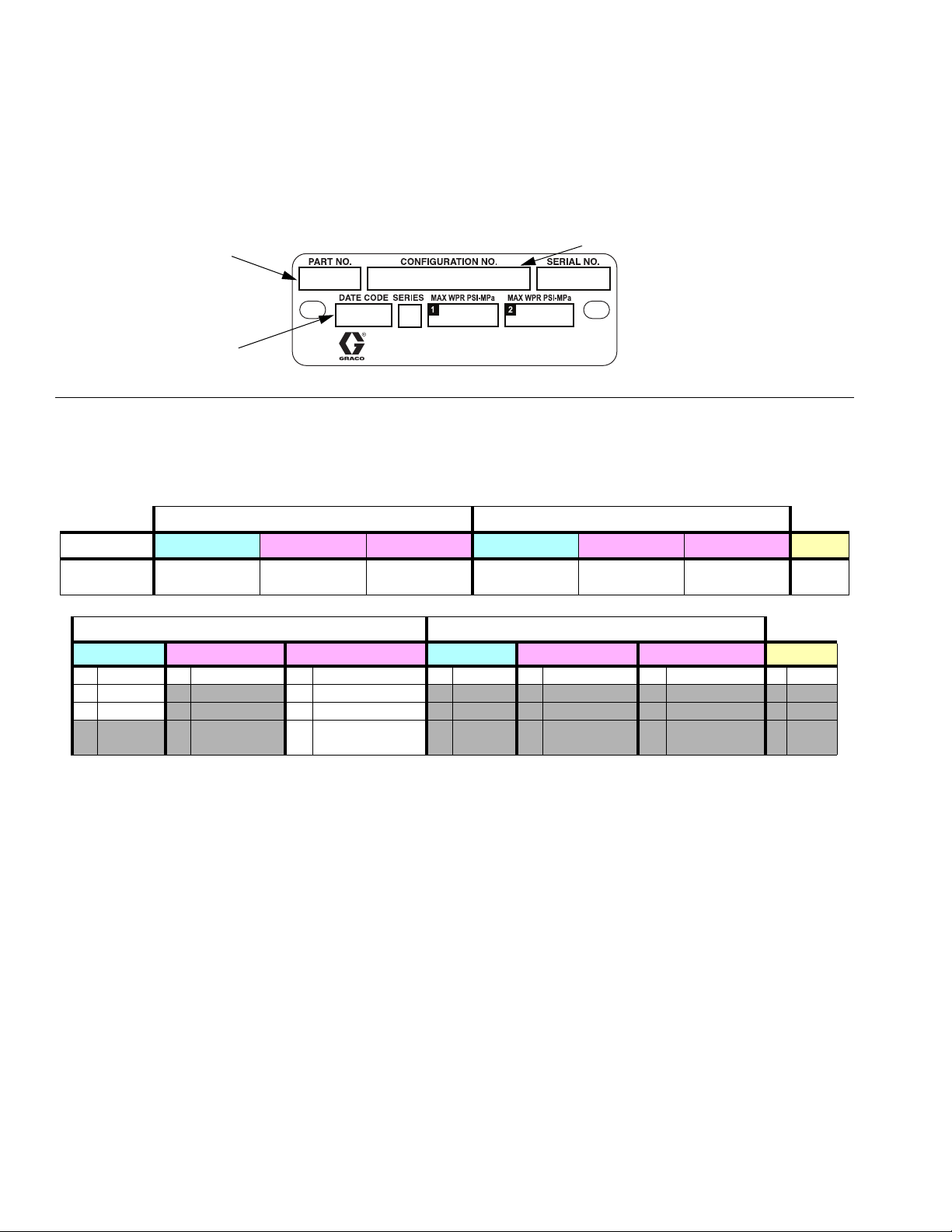
Configuration Number Matrix
Check the identification plate (ID) for the 12-digit Configuration Number of your pump. Use the following matrix to
define the components of your pump.
FIG. 1 Example of the G-Chem Assembly Identification Plate
G-Chem Beam Pump Assembly Configuration Code
Sample Configuration Number: CI-12E-2XF-000-0
Side 1 Side 2
CI 2 X F 0 0 0 0
Chemical
Injection
Plunger Size Plunger Coating Seal Material Plunger Size Plunger Coating Seal Material Qualifier
Side 1 Side 2
Plunger Size Plunger Coating Seal Material Plunger Size Plunger Coating Seal Material Qualifier
2 1/4” X Chromex F FKM 0 None 0 None 0 None 0 None
33/8”
51/2” HTFE/P
GHNBR
J PTFE w/FFKM
checks
4 3A6349C
Page 5
Fluid Module Configuration Code
A30970 ########
A 2500(17
)
# ####
Graco Inc., P.O. Box 1441
Mpls, MN 55440 USA
CI-25-XF-0
Model Number
Configuration Number
Date Code
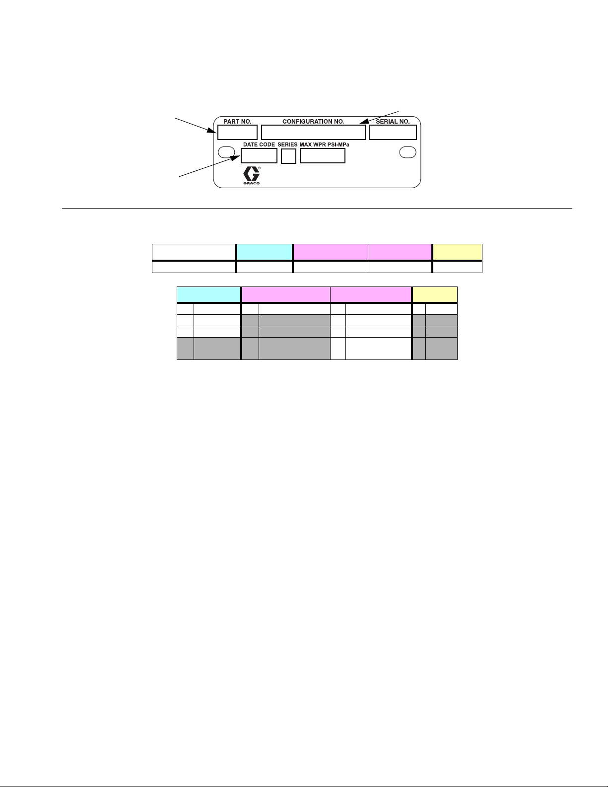
FIG. 2 Example of the Fluid Module Identification Plate
Sample Configuration Number: CI-25-XF-0
CI 25 X F 0
Chemical Injection Plunger Size Plunger Coating Seal Material Qualifier
Plunger Size Plunger Coating Seal Material Qualifier
25 1/4” X Chromex F FKM 0 None
38 3/8” G HNBR
50 1/2” HTFE/P
Configuration Number Matrix
J PTFE w/FFKM
checks
3A6349C 5
Page 6
Warnings
Warnings
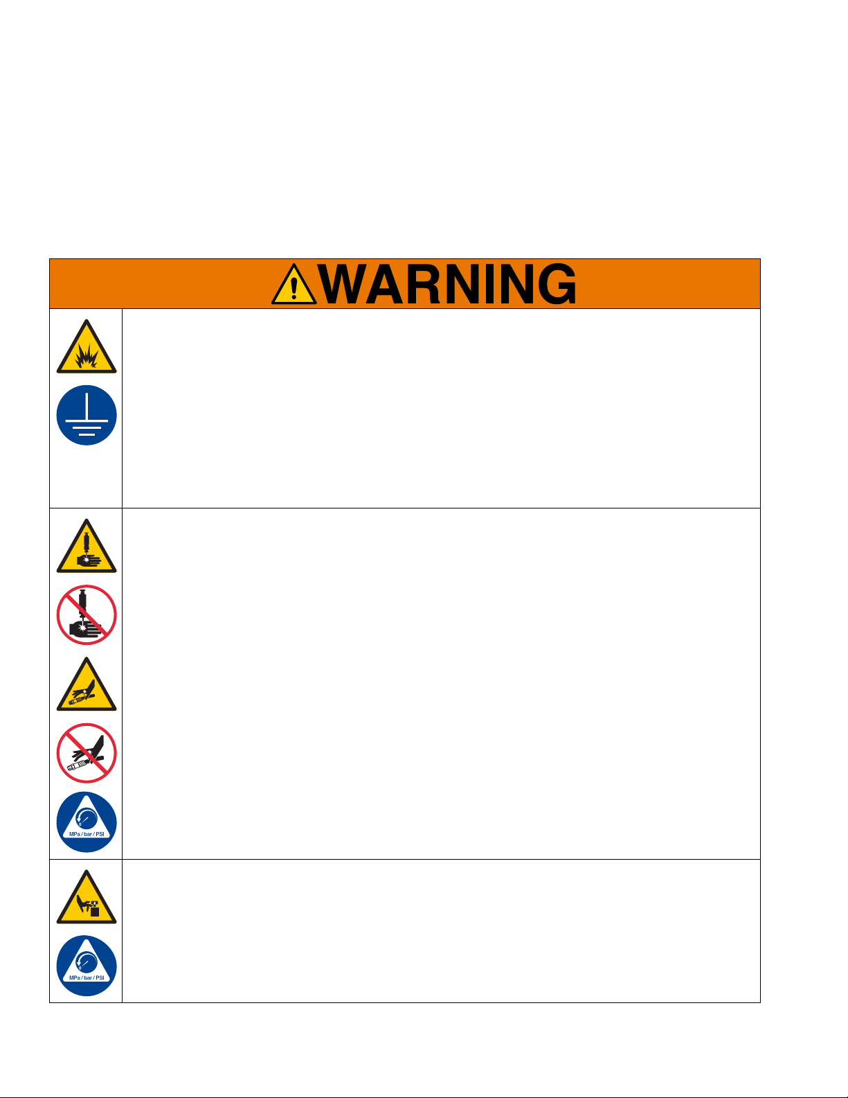
The following warnings are for the setup, use, grounding, maintenance, and repair of this equipment. The exclamation point symbol alerts you to a general warning and the hazard symbols refer to procedure-specific risks. When
these symbols appear in the body of this manual or on warning labels, refer back to these Warnings. Product-specific
hazard symbols and warnings not covered in this section may appear throughout the body of this manual where
applicable.
FIRE AND EXPLOSION HAZARD
When flammable fluids are present in the work area be aware that flammable fumes can ignite or
explode. To help prevent fire and explosion:
• Use equipment only in well ventilated area.
• Eliminate all ignition sources, such as cigarettes and portable electric lamps.
• Ground all equipment in the work area.
• Keep work area free of debris, including rags and spilled or open containers of solvent.
• Do not plug or unplug power cords or turn lights on or off when flammable fumes are present.
• Use only grounded hoses.
• Stop operation immediately if static sparking occurs or you feel a shock. Do not use equipment until
you identify and correct the problem.
• Keep a working fire extinguisher in the wor k ar ea .
SKIN INJECTION HAZARD
High-pressure fluid from dispensing device, hose leaks, or ruptured components will pierce skin. This
may look like just a cut, but it is a serious injury that can result in amputation. Get immediate surgical
treatment.
• Do not put your hand over the fluid outlet.
• Do not stop or deflect leaks with your hand, body, glove, or rag.
• Follow the Pressure Relief Procedure when you stop dispensing and before cleaning, checking, or
servicing equipment.
• Tighten all fluid connections before operating the equipment.
• Check hoses and couplings daily. Replace worn or da m age d pa rt s imm ed ia tely .
MOVING PARTS HAZARD
Moving parts can pinch, cut or amputate fingers and other body parts.
• Keep clear of moving parts.
• Do not operate equipment with protective guards or covers removed.
• Pressurized equipment can start without warning. Befo re checking, moving, or servicing equ ipment,
follow the Pressure Relief Procedure and disconnect all power sources.
6 3A6349C
Page 7
Warnings
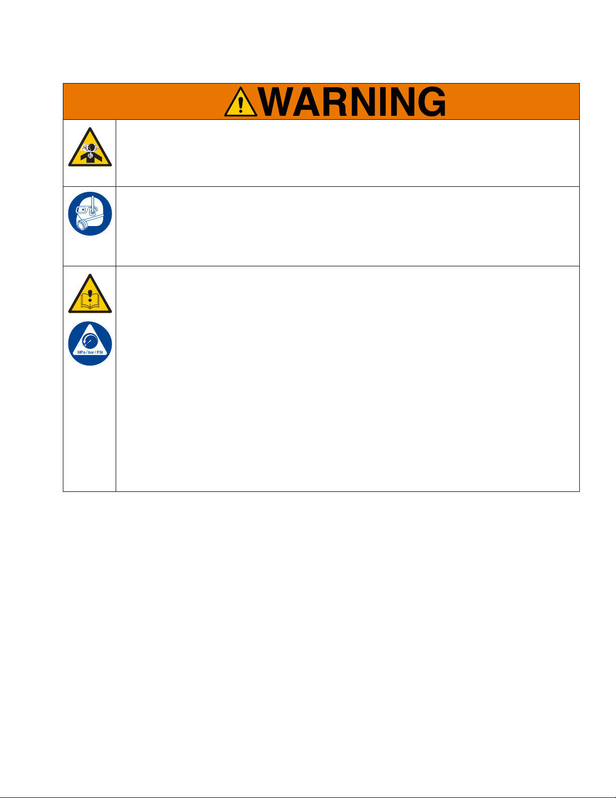
TOXIC FLUID OR FUMES HAZARD
Toxic fluids or fumes can cause serious injury or death if splashed in the eyes or on skin, inhaled, or
swallowed.
• Read Safety Data Sheet (SDS) to know the specific hazards of the fluids you are using.
• Store hazardous fluid in approved containers, and dispose of it according to applicable guidelines.
PERSONAL PROTECTIVE EQUIPMENT
Wear appropriate protective equipment when in the work area to help prevent serious injury, including
eye injury, hearing loss, inhalation of toxic fumes, and burns. Protective equipment includes but is not
limited to:
• Protective eyewear, and hearing protection.
• Respirators, protective clothing, and gloves as recommended by th e fluid and solvent manufacturer.
EQUIPMENT MISUSE HAZARD
Misuse can cause death or serious injury.
• Do not operate the unit when fatigued or under the influence of drugs or alcohol.
• Do not exceed the maximum working pressure or temperature rating of the lowest rated system component. See Technical Specifications in all equipment manuals.
• Use fluids and solvents that are compatible with equipment wetted parts. See Technical Specifica-
tions in all equipment manuals. Read fluid and solve nt manufacturer’s warnings. Fo r complete information about your material, request Safety Data Sheets (SDSs) from distributor or retailer.
• Turn off all equipment and follow the Pressure Relief Procedure when equipment is not in use.
• Check equipment regularly. Repair or replace wo rn or damaged parts immediately with genuine man ufacturer’s replacement parts only.
• Do not alter or modify equipment. Alterations or modifications may void agency approvals and create
safety hazards.
• Make sure all equipment is rated and approved for the environment in which you are using it.
• Use equipment only for its intended purpose. Call your distributor for information.
• Route hoses and cables away from traffic areas, sharp edges, moving parts, and hot surfaces.
• Do not kink or over bend hoses or use hoses to pull equipment.
• Keep children and animals away from work area.
• Comply with all applicable safety regulations.
3A6349C 7
Page 8
Installation
Installation
To avoid injury due to unexpected moving parts,
remove power to the pumpjack and wait for the walking beam to stop moving before performing any task
on the G-Chem pump. The G-Chem pump is directly
influenced by the motion of the pumpjack’s walking
beam, and the pump is inactive only when the walking
beam is unable to move.
Grounding
The equipment must be grounded to reduce the risk
of static sparking. Static sparking can caus e fum es t o
ignite or explode. Grounding provides an escape wire
for the electric current.
Pump: grounded through fluid lines.
Fluid lines: use only electrically conductive lines.
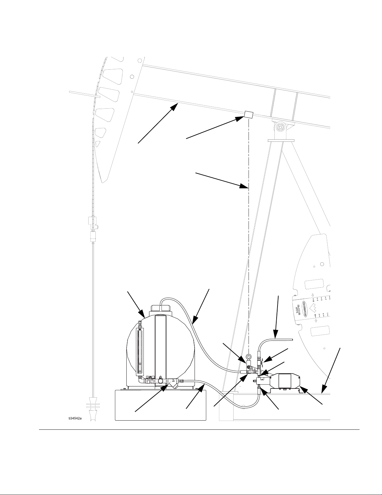
Typical Installation
FIG. 3 is an example of an installation with a G-Chem
chemical injection beam pump. Your installation may differ from what is shown here. (See Accessories on
page 8.) The G-Chem beam pump (A) and the swivel
block (B) are the only components in F
Graco. All other components are supplied by customer.
Key:
A G-Chem Beam Pump
B Swivel Block and Eye Bolt
CTank
D Pressure Relief Valve (Required)
E Inlet Line
F Outlet Line
G Pressure Relief Line
H Inlet Port
JOutlet Port
K Manifold Assembly (includes y-strainer and fluid shutoff
valve (L))
L Fluid Shutoff Valve (inlet & outlet) (Required)
M Pumpjack Base (I-Beam)
N Cable/Rod/Pipe
P Walking Beam
R Beam Clamp
IG. 3 supplied by
Fluid supply container: follow local code.
Accessories
Install the following required accessories in the order
shown in a typical installation (see F
using adapters as necessary.
• Fluid filter (Y-Strainer) (included in K): with a 60
mesh (250 micron) stainless steel element to filter
particles from the fluid before in reaches the pump.
• Fluid shutoff valves (L): shuts off fluid flow.
• Pressure relief valve (D): overload protection.
IG. 3 on page 9)
Flush Before Using Equipment
The equipment was tested with lightweight oil, which is
left in the fluid passages to protect parts. To avoid contaminating your fluid with oil, flush the equipment with a
compatible solvent before using the equipment. See
Flush the Equipment, page 12.
8 3A6349C
Page 9
Installation
A
B
F
E
G
C
D
H
J
N
K
L
M
R
P
FIG. 3 Typical G-Chem beam pump installation with pumpjack
3A6349C 9
Page 10

Installation
21 in.
6 in.
122
A
8
Pumpjack Connections
1. Remove power to the pumpjack and wait for the
pumpjack to stop moving.
2. Attach a cable (N) to the walking beam (P) using a
beam clamp (R) or other connection method (both
user-supplied).
• Place the beam clamp (R) on the walking beam
(P) where the vertical travel is, at most, 21 in.
(53.34 cm), which is the maximum travel of the
G-Chem pump’s lever arm.
4. Securely clamp or bolt the G-Chem pump (A) to the
pumpjack base (M) using the pump’s supplied
base (112).
• The G-Chem pump (A) is shipped with the sup-
plied base (112) already attached.
5. Connect the lever arm (122) to the walking beam
(P) by routing the end of the cable (N) through the
eye bolt (8) on the supplied swivel block (B).
6. Ensure there is no slack in the cable (R) when the
G-Chem pump (A) is maximum stroke (setting “1”
on the lever arm (122) and “Full” on the stroke
adjust). Refer to Adjust the Pump Stroke on
page 14.
FIG. 4 Lever arm range of travel
3. Position the G-Chem pump (A) on the pumpjack
base (M) so that the walking beam (P) provides a
straight upward pull as it rises.
• The lever arm (122) must be able to travel 6 in.
below the base of the G-Chem pump (A) to
achieve maximum flow.
10 3A6349C
Page 11

Fluid Connections
201
215
210, 211
216
122
112
101
7
8
Installation
1. With the pumpjack off, r emove and discard the caps
on the check valves (215 and 216).
FIG. 5 G-Chem Beam Pump Components
Key:
7 Swivel Block
8Eye Bolt
101 Drive Housing
112 Mounting Panel
122 Lever Arm
201 Fluid Cylinder
210 Bleed Valve
211 Bleed Needle
215 Inlet Check Valve
216 Outlet Che ck Valve
3. Install a pressure relief valve (D) on the outlet side
of the pump. See F
IG. 3 on page 9.
In the event of a fluid line blockage, to reduce the risk
of skin injection and damage to the pump, ensure the
pressure relief valve is set at or below the maximum
working pressure of the pump.
4. Set the pressure relief valve at or below the maximum working pressure of the pump.
5. Connect a 1/4 npt(f) fluid line from the outlet check
valve (J) to the injection point.
2. Connect a 1/4 npt(f) fluid line fro m the fluid source to
the inlet check valve (215).
3A6349C 11
Page 12

Operation
Operation
To avoid injury due to unexpected moving parts,
remove power to the pumpjack and wait for the walking beam to stop moving before performing any task
on the G-Chem pump. The G-Chem pump is directly
influenced by the motion of the pumpjack’s walking
beam, and the pump is inactive only when the walking
beam is unable to move.
Pressure Relief Procedure
Follow the Pressure Relief Procedure whenever
you see this symbol.
Flush the Equipment
To avoid fire and explosion, always ground equip ment
and waste container. To avoid static sparking and
injury from splashing, always flush at the lowest possible pressure.
• Check fittings for leaks and tighten as necessary.
• Flush with a fluid that is compatible with the fluid
being dispensed and the equipment’s wetted parts.
This equipment stays pressurized until pressure is
manually relieved. To help prevent serious injury from
pressurized fluid, such as skin injection and splashing
fluid, follow the Pressure Relief Procedure when
you stop dispensing and before cleaning, checking, or
servicing the equipment.
NOTE: Always discharge fluid into an approved container or location.
1. Remove power to the pumpjack and wait for the
pumpjack to stop moving.
2. Shut off the inlet (E) and outlet (F) lines using shutoff valves (L). See F
3. Slowly loosen the fitting connected to the outlet
check valve (216) to relieve downstream fluid pressure. See F
4. Open the bleed needle (211) on the end of the
pump cylinder (201) to relieve internal pump pressure.
IG. 3 on page 8.
IG. 3 on page 9.
1. Follow the Pressure Relief Procedure.
2. Disconnect lever arm (122) from the pumpjack.
3. Connect the inlet check valve (215) to the supply
source of the flushing fluid. See F
4. Connect the outlet check valve (216) to a waste reservoir.
5. Operate the lever arm (122) by hand until the dispensed fluid is predominantly flushing fluid.
6. Follow the Pressure Relief Procedure.
7. Reconnect the lever arm (122) to the pumpjack.
Refer to Pumpjack Connections, page 10.
IG. 3 on page 8.
5. Disconnect and cap the inlet (E) and outlet (F) fluid
lines.
12 3A6349C
Page 13

Operation
Prime the Pump
NOTICE
To avoid potential damage to equipment, verify that all
system valves are open before priming the pump.
1. Remove power to the pumpjack and wait for the
pumpjack to stop moving.
2. Disconnect lever arm (122) from the pumpjack.
3. Verify all connections and fluid lines are tight.
4. Verify only the inlet valve (215) is open.
5. Place a chemical compatible bucket under the bleed
valve (210).
6. In order to prime the pu mp, turn the bleed needle
(211) counterclockwise.
7. Operate the lever arm (122) by hand to prime the
pump.
8. The pump is prime d when discharge from the bleed
valve (210) has transitioned from air, to bubbly liquid
chemical, to pure liquid chemical.
Calibrate Chemical Dosage
1. With the pumpjack turned off, set the stroke adjustment of the pump to an estimated setting for the
desired flow rate. Refer to Adjust the Pump
Stroke, page 14, and Baseline Chemical Dosage
Settings, page 16.
2. Follow the instr uctions provided with your calibration
gauge.
3. Adjust the stroke adjustment accordingly after the
test is performed. Increasing the stroke adjustment
of the pump will increase the pump flow rate.
4. If a slower flow is desired, slow the pumping rate of
the pumpjack, or adjust the orientation of the lever
arm by removing the retaining clip (123) at the base
of the lever arm (122) and rotating the handle to a
different position on the octagonal shaft. This will
lengthen or shorten the lever arm stroke.
5. Repeat the instructions provided with your calibration gauge to verify changes.
6. Repeat steps 3 - 5, as necessary, until the desired
flow rate is achieved.
9. Turn the bleed ne edle (211) clockwise until tight and
verify that fluid has stopped draining from the port.
10. Reconnect the lever arm (122) to the pumpjack.
Refer to Pumpjack Connections, page 10.
3A6349C 13
Page 14

Operation
128
127
3/4
Full
1/2
209
121
Stroke holes
Adjust the Pump Stroke
The stroke of the G-Chem pump can be adjusted by a
combination of a pin in the pump and the lever arm.
Stroke Adjustment with Pin Settings
The pump has three defined stroke adjustment positions.
1. Follow the Pressure Relief Procedure on page 12.
2. Disconnect the G-Chem pump (A) from the pumpjack by removing the swivel block (B) from the lever
arm (122).
3. Expose the drive shaft by loosening the fasteners
(128) and removing the guard (127). The fasteners
are captive and will remain with the guard.
6. Align the desired stroke hole (1/2, 3/4, or Full) with
hole in the fluid plunger (209). Use a screwdriver to
push in the pin (120).
FIG. 7 Stroke adjustment - pin positions
7. Push the split ring (121) into place to cover the
pin (120).
FIG. 6 Expose the drive shaft
4. Push the split ring (121) left or right to expose the
dowel pin (120) in one of the stroke holes.
5. Push out the pin (120) using a screwdriver or punch.
8. Replace the gu ard (127) and tighten the fasteners
(128).
9. Reconnect the G-Chem pump (A) to the pumpjack
by reattaching the swivel block (B) to the level
arm (122).
14 3A6349C
Page 15

Stroke Adjustment with Lever Arm Settings
123
122
105
The handle has two defined stroke adjustment positions.
1. Follow the Pressure Relief Procedure on page 12.
2. Disconnect the G-Chem pump (A) from the pumpjack by removing the swivel block (B) from the lever
arm (122).
3. Remove the retaining clip (123) from the lever
arm (122) using a flat-blade screwdriver.
4. Remove the lever arm (122) from the shaft (105).
5. Reorient the lever arm ( 122) so the arrow on the
lever arm lines up with either “1” or “2” on the
shaft (105).
Operation
FIG. 8 Stroke adjustment - lever arm positions
6. Reinstall the lever arm (122) in the desired orientation.
7. Reinstall the retaining clip (123) onto the shaft using
your fingers or a pair of pliers.
8. Reconnect the G-Chem pump (A) to the pumpjack
by reattaching the swivel block (B) to the level
arm (122).
3A6349C 15
Page 16

Operation
Baseline Chemical Dosage Settings
See Adjust the Pump Stroke, page 14, to adjust stroke settings. CPM (cycles per minute) is determined by the
pumpjack speed. To use these charts, find the desired flow rate for the plunger size and adjust the pin and lever arm
as necessary.
1/4 in. Plunger 3/8 in. Plunger 1/2 in. Plunger
CPM
5
10
15
Pin
Setting
3/4 2 0.3 (1.1) 3/4 2 0.7 (2.6) 3/4 2 1.2 (4.5)
1/2 1 0.5 (1.9) 1/2 1 1.1 (4.2) 1/2 1 1.8 (6.8)
Full 2 0.6 (2.3) Full 2 1.5 (5.7) Full 2 2.6 (9.8)
3/4 1 0.7 (2.6) 3/4 1 1.6 (6.1) 3/4 1 3.2 (12.1)
Full 1 1.2 (4.5) Full 1 2.8 (10.6) Full 1 5.0 (18.9)
3/4 2 0.5 (1.9) 3/4 2 1.3 (4.9) 3/4 2 2.3 (8.7)
1/2 1 1.0 (3.8) 1/2 1 2.2 (8.3) 1/2 1 3.6 (13.6)
Full 2 1.2 (4.5) Full 2 2.9 (11.0) Full 2 5.1 (19.3)
3/4 1 1.5 (5.7) 3/4 1 3.2 (12.1) 3/4 1 6.5 (24.6)
Full 1 2.5 (9.5) Full 1 5.7 (12.6) Full 1 10.0 (37.9)
3/4 2 0.8 (3.0) 3/4 2 2.0 (7.6) 3/4 2 3.5 (13.2)
1/2 1 1.4 (5.3) 1/2 1 3.3 (12.5) 1/2 1 5.4 (20.4)
Full 2 1.8 (6.8) Full 2 4.4 (16.7) Full 2 7.7 (29.1)
3/4 1 2.2 (8.3) 3/4 1 4.8 (18.2) 3/4 1 9.7 (36.7)
Full 1 3.7 (14.0) Full 1 8.5 (32.2) Full 1 15.0 (56.8)
Lever
Setting
Approximate
Flow Rate
[GPD (LPD)]
Pin
Setting
Lever
Setting
Approximate
Flow Rate
[GPD (LPD)]
Pin
Setting
Lever
Setting
Approximate
Flow Rate
[GPD (LPD)]
NOTE: Not all stroke adjustment combinations are pos-
sible.
16 3A6349C
Page 17

Maintenance
Preventive Maintenance
Schedule
The operating conditions of your particular pump determines how often maintenance is required. Establish a
preventive maintenance schedule by recording when
and what kind of maintenance is needed, and then
determine a regular schedule for checking your pump.
Tighten Threaded Connections
Check that all threaded connections are tight at routine
intervals.
Tighten Packings
Operation
The packings included in your pump have the ability to
be adjusted to stop leaks that develop when the seals
are worn. If a leak develops in the pump’s fluid section,
tighten the packing nut clockwise by 1/16th of a turn, or
lower, until the leak is eliminated. The life of the packing
can be affected by over-tightening the packings. If the
packing nut needs to be tightened repeatedly after short
intervals, replace the packing.
Storage
If the pump is going to be stored for long periods, it is
recommended that the pump be flushed with a
light-weight oil or rust prohibiter to protect pump components. Store the pump with protective fluid inside whenever possible.
3A6349C 17
Page 18

Troubleshooting
Troubleshooting
1. Follow Pressure Relief Procedure, pa ge 12,
before checking or repairing the pump.
Problem Cause Solution
Air bubbles in fluid Suction line is loose Tighten suction line
Fluid leaking Loose fittings Tighten fittings
Worn or damaged seals and/or packing
Lever arm moving, but fluid not moving
Pump stalled Check pump for contamination
Air in pump Prime pump
Worn or damaged check valve seals Replace inlet and outlet check valves
2. Check all possible problems and causes be fore disassembling the pump.
Adjust or tighten seals and/or packing. If leak persists, replace seals
and/or packing.
18 3A6349C
Page 19

Repair
128
127
3
201
209
101
120
201
Packing
Stack
207
206
204
205
204
205
203
202
Pump Repair
1. Remove power to the pumpjack and wait for the
pumpjack to stop moving.
2. Follow the Pressure Relief Procedure.
3. Disconnect lever arm (122) from the pumpjack.
Repair
4. Expose the drive shaft by loosening the fasteners
(128) and removing the guard (127). The fasteners
are captive and will remain with the guard.
FIG. 9 Expose the drive shaft
5. Remove the screws (3) and slide the fluid cylinder
away from the drive housing (101).
NOTE: The plunger (209) will stay within the drive
housing (101) unless the dowel pin (120) is
removed. The dowel pin is held in place by a split
ring that can be push aside to free the pin. It is not
necessary to remove the plunger (209) unless it is
damaged and needs to be replaced.
FIG. 10 Disconnect the fluid cylinder
6. Remove packing nut (207) from fluid cylinder (201).
3A6349C 19
FIG. 11 G-Chem Pump Repair
Page 20

Repair
7. Carefully remove the packing stack (203-206) and
the spacer (202) from the fluid cylinder (201).
8. Replace the packing stack (203-206). Inspect the
spacer (202) and replace, if necessary. Lubricate
prior to reassembly.
9. Replace the packing nut (207) assembly into fluid
cylinder. Tighten until hand tight and the flange of
the packing nut (207) is below the surface of the
fluid cylinder (201).
10. Slide the fluid cylinder (201) onto the plunger (209)
and use the screws (3) to attach the fluid cylinder
(201) to the drive housing (101).
NOTE: Install the plunger (209) first if it was
removed, and secure it with the dowel pi n (120) and
split ring (121). Refer to Stroke Adjustment with
Pin Settings, on page 14, for specific placement of
the pin (120) and ring (121).
11. Replace the guard (127) and tighten the fasteners
(128).
20 3A6349C
Page 21

Parts
6
8
9
7
130
123
102
103
105
112
113
114
119
121
109
120
128
3
133
127
129
131
101
125
130
106
115
118
116
117
108
110
107
6
6
5
6
5
122
Fluid Module,
see page 23.
G-Chem Beam Drive Module
Configuration CI-2XF-000-0 shown
Parts
3A6349C 21
Page 22
Parts
G-Chem Drive Module Parts List
Ref. Part Description Qty
3 100644 Screw, socket head cap 3
5 -- Nut, hex 2
6 -- Washer, flat 4
7 -- Block, swivel 1
8 -- Bolt, eye 1
9 -- Screw, hex head cap 1
101 -- Housing, drive 1
102 -- Bearing, retainer 1
103 -- Bearing, sleeve 1
105 -- Shaft 1
106 B32708 Bearing, CIP carriage 1
107 -- Carriage, plunger return 1
108 B32711 Block, plunger return 1
109 -- Adjuster, stroke 1
110 15B588 Screw, socket head cap;
included with plunger return
block (ref 108)
112 B32949 Panel, mounting 1
113 115814 Washer, flat; included with
mounting panel (ref 112)
114 -- Fastener, SCHS; included
with mounting panel (ref 112)
115 -- Washer, plastic shaft 1
116 B32708 Cam, eccentric, CIP 1
117 -- Deep Groove Ball Bearing,
included with CIP eccentric
cam (ref 116)
118 -- Key, square; included with
CIP carriage bearing
(ref 106) and CIP eccentric
cam (ref 116)
119 -- Screw, set 1
120 B32268 Pin, dowel 1
121 -- Ring, split; included with
dowel pin (ref 120)
122 -- Arm, shaft lever 1
123 -- Clip, shaft retaining 1
125 -- Plug, Simplex 1
127 B32787 Guard 1
4
4
4
1
1
1
Ref. Part Description Qty
128 -- Screw, captive; included with
guard (ref 127)
129 -- Label, branding ; included
with guard (ref 127)
130
131
133 -- Cap Plug, threaded 2
15H108 Label, pinch warning safety 3
17G318 Label, multiple warning safety 1
2
1
Replacement Danger and Warning labels, tags, and
cards are available at no cost.
22 3A6349C
Page 23
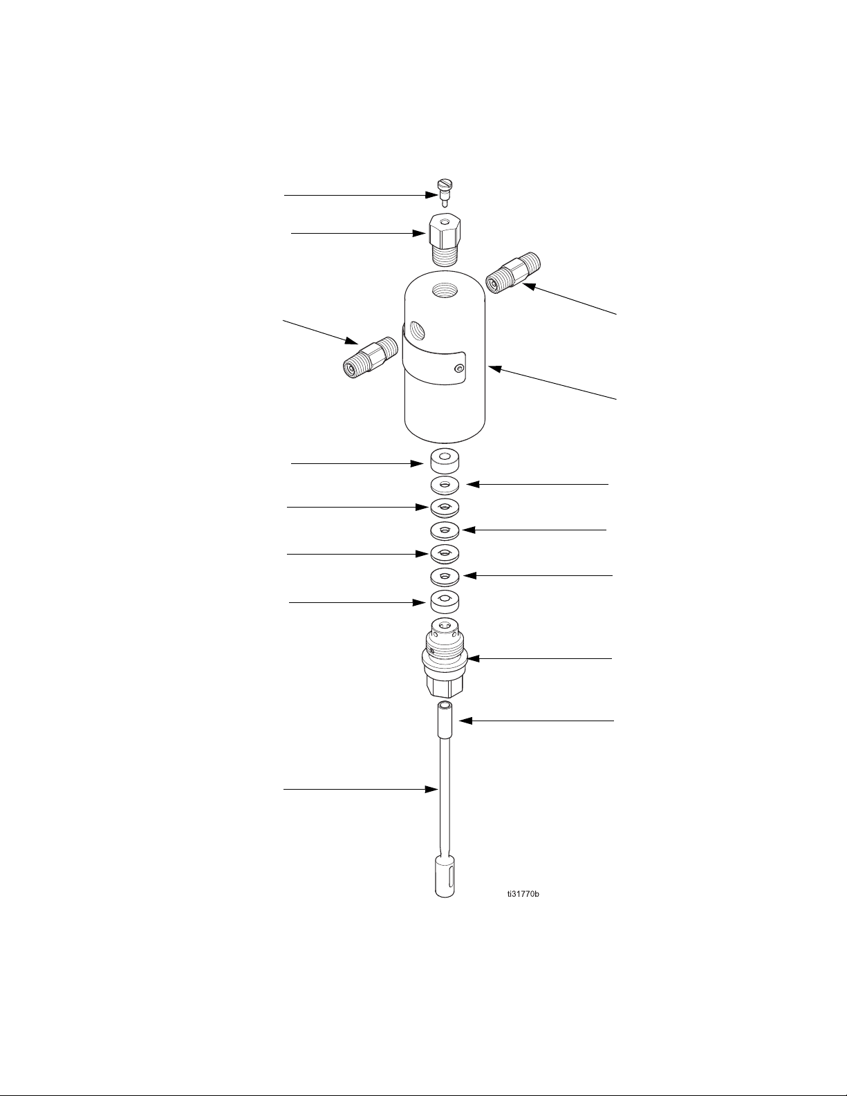
G-Chem Beam Fluid Module
211
215
210
216
202
205
205
206
201
209
203
204
204
208
207
Parts
3A6349C 23
Page 24
Parts
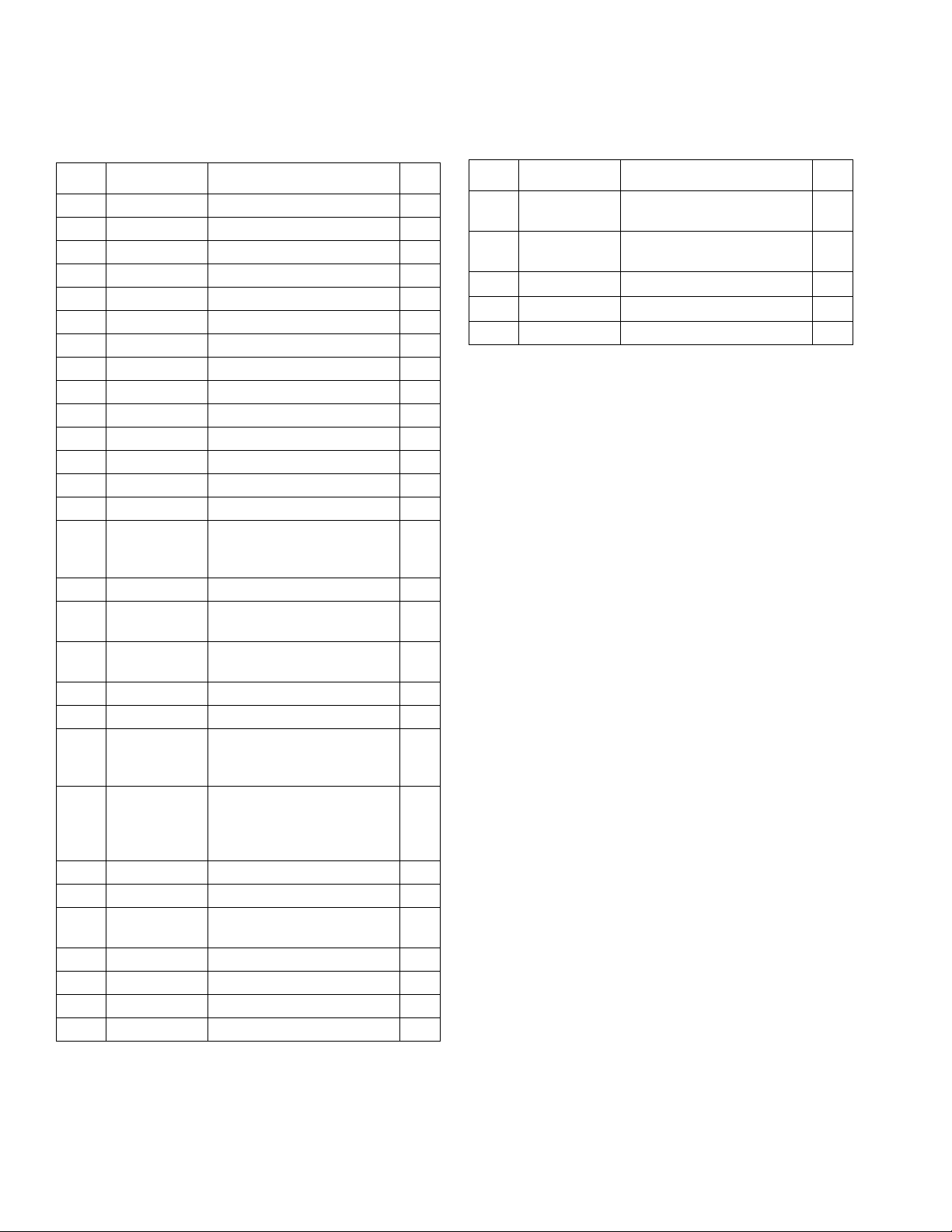
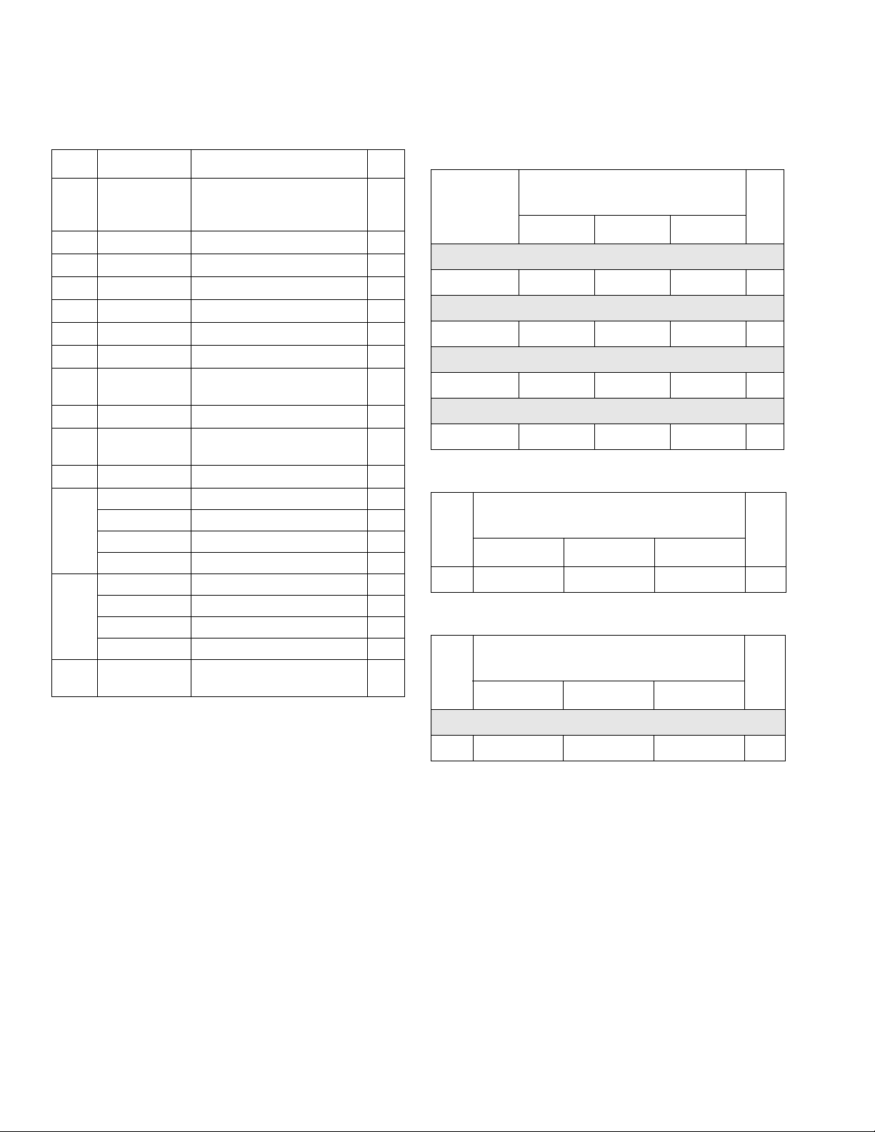
G-Chem Fluid Module Parts List
Ref. Part Description Qty
201 See Kits and
Accessories,
page 25
202
203
204
205
206
207
208
209
210
211
215
216
217
-- Spacer, packing nut 1
See Table 1 Adapter, male, vee stack 1
See Table 1 Packing, vee, plastic 2
See Table 1 Packing, vee, rubber 2
See Table 1 Adapter, female, vee stack 1
See Table 2 Nut, packing 1
-- Bearing, sleeve; included
See Table 3 Plunger 1
B32872 Valve, bleed; includes bleed
17F572 Needle, bleed 1
B32733 Valve, inlet check; FKM 1
B32735 Valve, inlet check; HNBR 1
B32857 Valve, inlet check; TFE/P 1
B32279 Valve, inlet check; FFKM 1
B32734 Valve, outlet check; FKM 1
B32736 Valve, outlet check; HNBR 1
B32858 Valve, outlet check; TFE/P 1
B32280 Valve, outlet check; FFKM 1
-- Nylon Ball, included with
Cylinder, fluid 1
1
with packing nut (ref 207)
1
needle (ref 211)
1
packing nut (207)
Table 1: Packing Kit (includes ref. 203 - 206)
Part Numbers by Fluid Plunger
Size Diameter
Ref
FKM
203 - 206 B32784 B32782 B32780
HNBR
203 - 206 B32785 B32783 B32781
TFE/P
203 - 206 B32854 B32855 B32856
PTFE
203 - 206 B32978 -- --
Table 2: Packing Nut
Part Numbers by Fluid Plunger Size
Diameter
Ref
207 B32776 B32775 B32774
Table 3: Fluid Plunger
Part Numbers by Fluid Plunger Size
Diameter
Ref
Qty.1/4 in. 3/8 in. 1/2 in.
1
1
1
1
Qty.1/4 in. 3/8 in. 1/2 in.
1
Qty.1/4 in. 3/ 8 in . 1/2 in.
Chromex-Coated 17-4 Stainless Steel
209 B32779 B32778 B32777
24 3A6349C
1
Page 25

Kits and Accessories
G-Chem Beam Pump
Part No. Description
B32045 225-750 PSI Pressure Relief Valve Kit
B32046 750-1500 PSI Pressure Relief Valve Kit
B32047 1500-2250 PSI Pressure Relief Valve Kit
B32048 2250-3000 PSI Pressure Relief Valve Kit
A30970 1/4” FKM: Chromex Fluid Module*
A30971 1/4” HNBR: Chromex Fluid Module*
A30980 3/8” FKM: Chromex Fluid Module*
A30981 3/8” HNBR: Chromex Fluid Module*
A30990 1/2” FKM: Chromex Fluid Module*
A30991 1/2” HNBR: Chromex Fluid Module*
A30973 1/4” PTFE: Chromex Fluid Module*
B32983 Shaft Kit (includes ref. 115, 105, and 122)
B32984 Lever Arm Kit (includes ref. 122, 123, and 130)
B32985 Counterweight Kit (includes ref. 5, 6, 7, 8, and 9)
B33072 Beam Attachment Kit (includes ref. R and 8)
B33066 Extra weight kit (includes ref. 5,6,7, and 9)F
Kits and Accessories
* Includes ref. 6, 201-211, 215, and 216
3A6349C 25
Page 26

Dimensions
Dimensions
G-Chem Beam Pump Dimensions
FIG. 12 G-Chem Pump Dimensions
A B C D E F G
13.8 in.
(35.1 cm)
26 3A6349C
9.3 in.
(23.6 cm)
4.6 in.
(11.7 cm)
7.4 in.
(18.8 cm)
18.4 in.
(46.7 cm)
3.3 in.
(8.4 cm)
12.7 in.
(32.3 cm)
Page 27

Technical Specifications
Technical Specifications
G-Chem Chemical Injection Pump
US Metric
Maximum fluid working pressure Varies by model. See Models and Approvals on page 3.
Environmental temperature range, ordinary location -40°–131°F -40°–55°C
Noise (dBa)
Maximum sound pressure
Inlet/Outlet Sizes
Fluid inlet size 1/4 in. npt(m)
Fluid outlet size 1/4 in. npt(m)
Materials of Construction
Pump/Check Valve Seal Material
Wetted Parts
Weight
G-Chem,1 pump 14.8 lb. 6.7 kg
See Configuration Chart on page 4 for seal material. All other packing
materials are UHMWPE and PTFE unless otherwise noted.
See Configuration Chart on page 4 for plunger material. All other
materials are 303 and 316 stainless steel unless otherwise noted.
<70 dBa
California Proposition 65
CALIFORNIA RESIDENTS
WARNING: Cancer and reproductive harm. – www.P65warnings.ca.gov.
3A6349C 27
Page 28

Graco Standard Warranty
Graco warrants all equipment referenced in this document which is manufactured by Graco and bearing its name to be free from defects in
material and workmanship on the date of sale to the original purchaser for use. With the exception of any special, extended, or limited warranty
published by Graco, Graco will, for a period of twelve months from the date of sale, repair or replace any part of the equipment determined by
Graco to be defective. This warranty applies only when the equipment is installed, operated and maintained in accordance with Graco’s written
recommendations.
This warranty does not cover, and Graco shall not be liable for general wear and tear, or any malfunction, damage or wear caused by faulty
installation, misapplication, abrasion, corrosion, inadequate or improper maintenance, negligence, accident, tampering, or substitution of
non-Graco component parts. Nor shall Graco be liable for malfunction, damage or wear caused by the incompatibility of Graco equipment with
structures, accessories, equipment or materials not supplied by Graco, or the improper design, manufacture, installation, operation or
maintenance of structures, accessories, equipment or materials not supplied by Graco.
This warranty is conditioned upon the prepaid return of the equipment claimed to be defective to an authorized Graco distributor for verification of
the claimed defect. If the claimed defect is verified, Graco will repair or replace free of charge any defective parts. The equipment will be returned
to the original purchaser transportation prepaid. If inspection of the equipment does not disclose any defect in material or workmanship, repairs
will be made at a reasonable charge, which charges may include the costs of parts, labor, and transportation.
THIS WARRANTY IS EXCLUSIVE, AND IS IN LIEU OF ANY OTHER WARRANTIES, EXPRESS OR IMPLIED, INCLUDING BUT NOT
LIMITED TO WARRANTY OF MERCHANTABILITY OR WARRANTY OF FITNESS FOR A PARTICULAR PURPOSE.
Graco’s sole obligation and buyer’s sole remedy for any breach of warranty shall be as set forth above. The buyer agrees that no other remedy
(including, but not limited to, incidental or consequential damages for lost profits, lost sales, injury to person or property, or any other incidental or
consequential loss) shall be available. Any action for breach of warranty must be brought within two (2) years of the date of sale.
GRACO MAKES NO WARRANTY, AND DISCLAIMS ALL IMPLIED WARRANTIES OF MERCHANTABILITY AND FITNESS FOR A
PARTICULAR PURPOSE, IN CONNECTION WITH ACCESSORIES, EQUIPMENT, MATERIALS OR COMPONENTS SOLD BUT NOT
MANUFACTURED BY GRACO. These items sold, but not manufactured by Graco (such as electric motors, switches, hose, etc.), are subject to
the warranty, if any, of their manufacturer. Graco will provide purchaser with reasonable assistance in making any claim for breach of these
warranties.
In no event will Graco be liable for indirect, incidental, special or consequential damages resulting from Graco supplying equipment hereunder, or
the furnishing, performance, or use of any products or other goods sold hereto, whether due to a breach of contract, breach of warranty, the
negligence of Graco, or otherwise.
FOR GRACO CANADA CUSTOMERS
The Parties acknowledge that they have required that the present document, as well as all documents, notices and legal proceedings entered into,
given or instituted pursuant hereto or relating directly or indirectly hereto, be drawn up in English. Les parties reconnaissent avoir convenu que la
rédaction du présente document sera en Anglais, ainsi que tous documents, avis et procédures judiciaires exécutés, donnés ou intentés, à la suite
de ou en rapport, directement ou indirectement, avec les procédures concernées.
Graco Information
For the latest information about Graco products, visit www.graco.com.
For patent information, see www.graco.com/patents.
TO PLACE AN ORDER, contact your Graco distributor or call to identify the neares t distributor.
Phone: 612-623-6921 or Toll Free: 1-800-328-0211 Fax: 612-378-3505
All written and visual data contained in this document reflects the latest product information available at the time of publication.
GRACO INC. AND SUBSIDIARIES • P.O. BOX 1441 • MINNEAPOLIS MN 55440-1441 • USA
Copyright 2017, Graco Inc. All Graco manufacturing locations are registered to ISO 9001.
Graco reserves the right to make changes at any time without notice.
Original instructions. This manual contains English. MM 3A6349
Graco Headquarters: Minneapolis
International Offices: Belgium, China, Japan, Korea
www.graco.com
Revision C, June 2020
 Loading...