

Page 1
Instructions/Parts
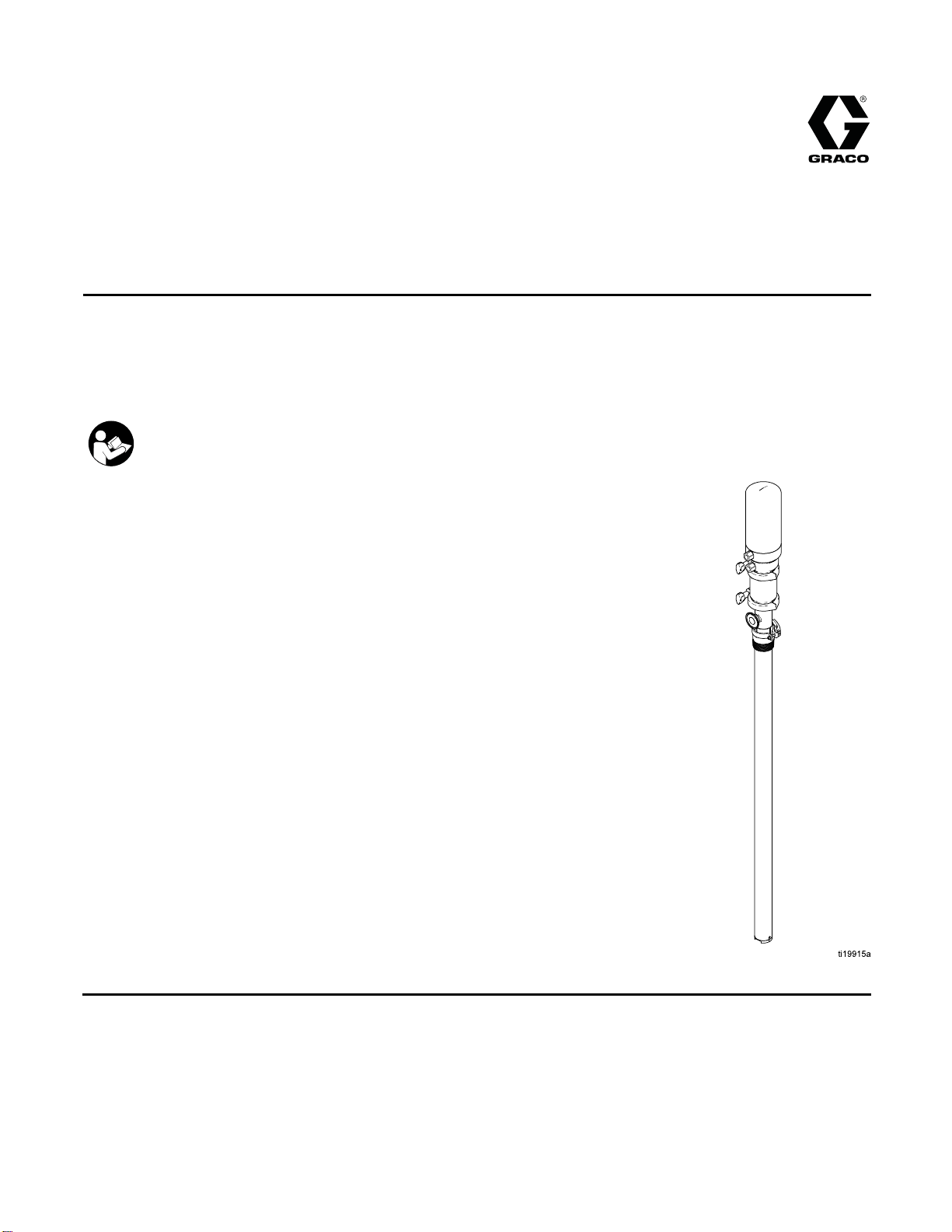
SaniForce® 2:1
Sanitary Piston
3A2977D
Pumps
For use in sanitary applications to transfer low- to medium-viscosity fluids. Use with non-flammable
liquids only. For professional use only.
Important Safety Instructions
Read all warnings and instructions in this manual.
Save these instructions.
Maximum F
psi (1.7 MPa, 17.0 bar)
luid Working Pressure: 250
EN
PROVEN QUALITY. LEADING TECHNOLOGY.
Page 2

Contents
Models............................................................... 3
Warnings ........................................................... 5
Installatio
Operation........................................................... 9
Maintenance ...................................................... 10
Troubles
n.......................................................... 7
Grounding ................................................... 7
Mounting ..................................................... 7
Setup .......................................................... 7
Pressure Relief Procedure............................ 9
Flush Before First Use.................................. 9
Adjusting the Pump Speed and
Pressure ........................................ 9
Pump Shut Down......................................... 9
Flushing Procedure ...................................... 10
Cleaning...................................................... 10
Tighten Threaded Connections ..................... 10
hooting.................................................. 11
Repair................................................................ 12
Disconnect the Air Motor .............................. 12
Air Motor Disassembly ................................. 12
Air Motor Reassembly .................................. 14
Disassemble the Pump................................. 16
Reassemble After Cleaning .......................... 17
Reconnect The Pump................................... 18
Notes................................................................. 19
Parts.................................................................. 20
Kits and Accessories........................................... 26
Dimensions ........................................................ 27
Performan
Technical Data ...................................................29
Graco Standard Warranty.................................... 30
ce Chart ............................................. 28
2
3A2977D
Page 3
Models
Models
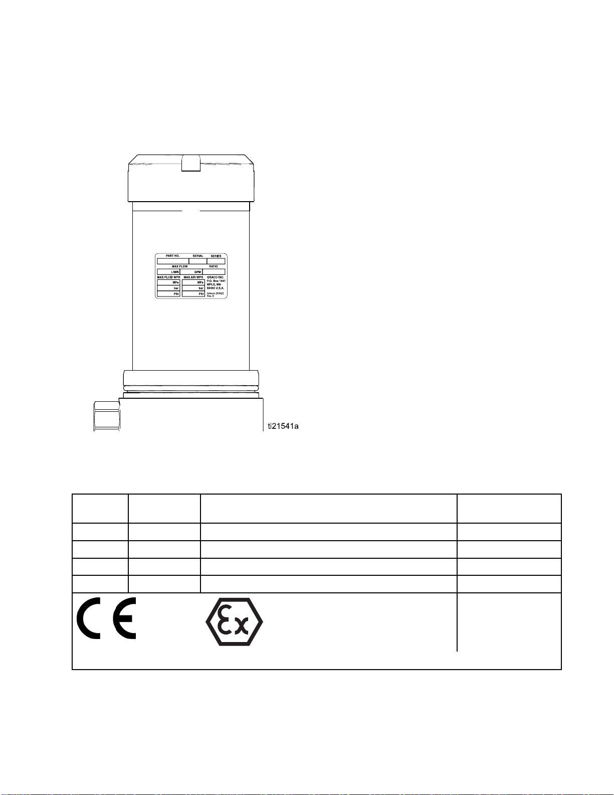
See ID tag on si
motor cover) f
or model number.
de of air motor (located under the
Maximum Air Inlet Pressure: 100 psi (0.7 MPa, 6.9 bar)
Maximum Fluid Working Pressure: 250 psi (1.7 MPa, 17.0 bar)
Pump
Model
24N300 Double Ball
24N344 Double Ball
046
24R
24R047 Double Ball
Pump Type Pump Description Packings
Drum Length (42 in., 107 cm Drum)
Tall
Tall Drum Length (42 in., 107 cm Drum) U-Cup, PTFE
ble Ball
Dou
Standard Drum Length (34 in., 86 cm Drum) U-Cup, UHMWPE
ndard Drum Length (34 in., 86 cm Drum)
Sta
II 2 GD c IIA T3
p, UHMWPE
U-Cu
up, PTFE
U-C
NOTE: See page
4 for FDA Material
Certification.
3A2977D 3
Page 4

Material Certification
SaniForce Product Family
Issue Date: April 24, 2013
All fluid contact materials in the SaniForce product family are FDA-Compliant and meet the United States
Code of Federal Regulations (CFR) Title 21, Section 177 or are of a corrosion resistant grade Stainless
Steel. This includes the below product groups:
✦ SaniForce 515, 1040, 1590, and 2150 Air-Operated Double Diaphragm Pumps
✦ SaniFo
✦ SaniForce 1590, 3150 HS 3–A Certified Air-Operated Double Diaphragm Pumps
✦ SaniForce 2:1, 5:1, 6:1, and 12:1 Air-Operated Piston Pumps
✦ SaniF
✦ SaniForce Diaphragm Pump and Piston Pump Bin Evacuation Systems
Quality Manager
Gra
rce 1590, 3150 HS Air-Operated Double Diaphragm Pumps
orce Diaphragm Pump and Piston Pump Drum Unloaders
co, Inc.
4
3A2977D
Page 5
Warnings
Warnings
The following
exclamation p
risks. When th
Product-spe
this manual w
cific hazard symbols and warnings not covered in this section may appear throughout the body of
warnings are for the setup, use, grounding, maintenance and repair of this equipment. The
oint symbol alerts you to a general warning and the hazard symbol refers to procedure-specific
ese symbols appear in the body of this manual or on labels refer back to these Warnings.
here applicable.
WARNING
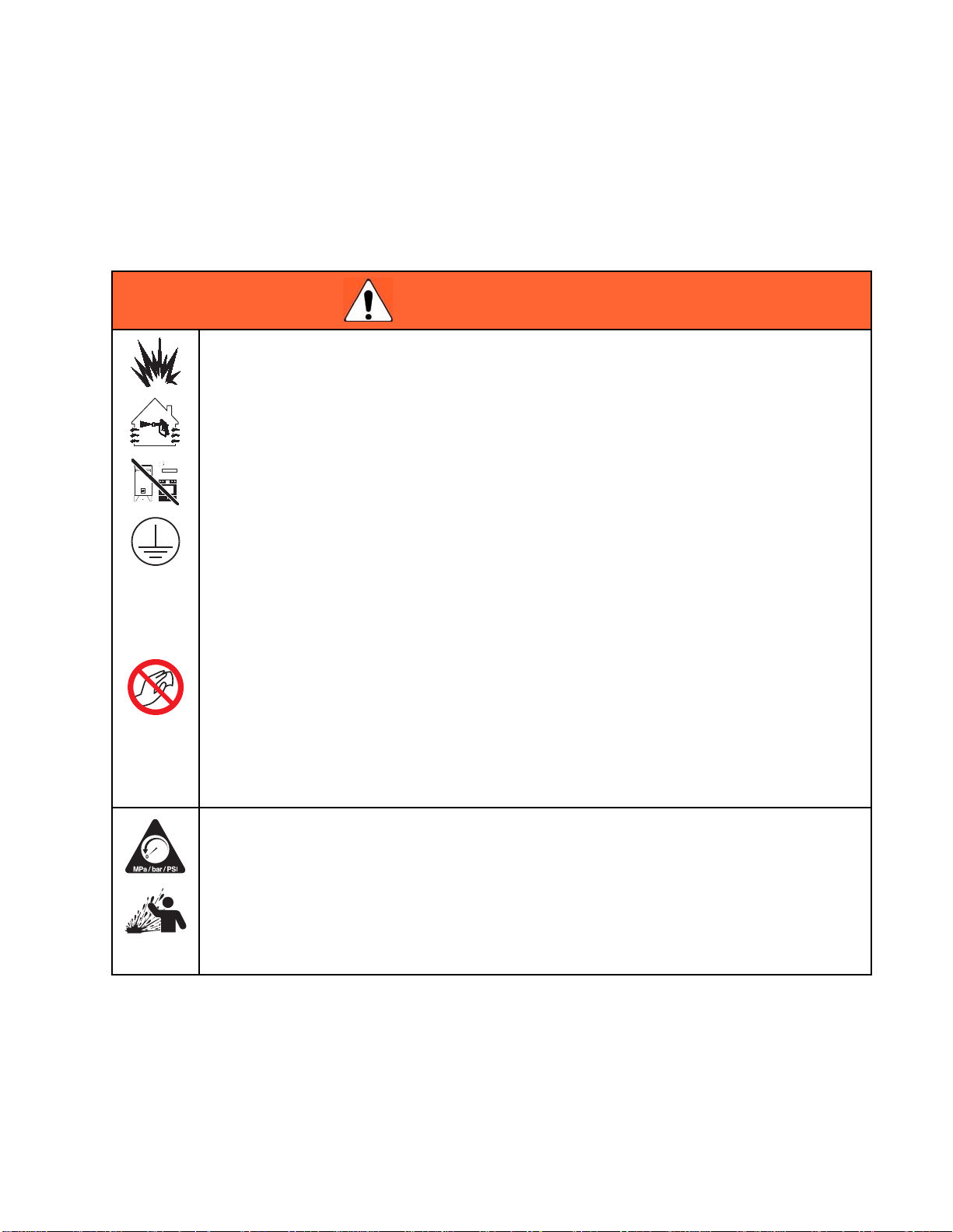
FIRE AND EXPLOSION HAZARD
Flammable fumes, such as solvent and paint fumes, in work area can ignite or explode. To help
prevent fire and explosion:
• Use equipm
• Eliminate all ignition sources; such as pilot lights, cigarettes, portable electric lamps, and
plastic drop cloths (potential static arc).
• Keep work area free of debris, including solvent, rags and gasoline.
• Do not plu
fumes are
• Ground all equipment in the work area. See Grounding instructions.
• Use only grounded hoses.
• Hold gun
they are
• Stop operation immediately if static sparking occurs or you feel a shock, Do not use
equipment until you identify and correct the problem.
• Keep a working fire extinguisher in the work area.
ent only in well ventilated area.
g or unplug power cords, or turn power or light switches on or off when flammable
present.
firmly to side of grounded pail when triggering into pail. Do not use pail liners unless
antistatic or conductive.
Static charge may build up on plastic parts during cleaning and could discharge and ignite
flammable vapors. To help prevent fire and explosion:
• Clean
• Do not
PRESSURIZED EQUIPMENT HAZARD
Flui
and c
• Follow the Pressure Relief Procedure when you stop spraying/dispensing and before
•Tig
• Check hoses, tubes, and couplings daily. Replace worn or damaged parts immediately.
plastic parts only in well ventilated area.
cleanwithadrycloth.
d from the equipment, leaks, or ruptured components can splash in the eyes oronskin
ause serious injury.
cleaning, checking, or servicing equipment.
hten all fluid connections before operating the equipment.
3A2977D 5
Page 6
Warnings
WARNING
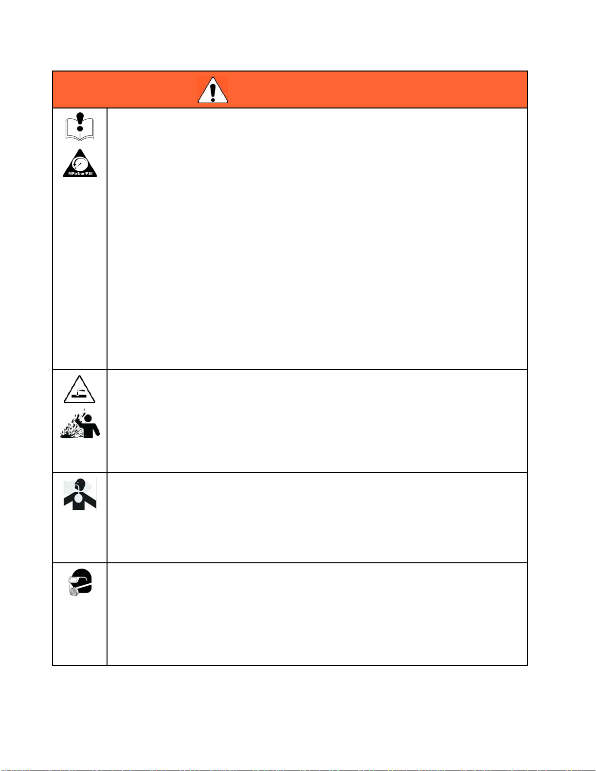
EQUIPMENT MISUSE HAZARD
Misuse can cause death or serious injury.
• Do not operat
• Do not exceed the maximum working pressure or temperature rating of the lowest rated
system component. See Technical Data in all equipment manuals.
• Use fluids and solvents that are compatible with equipment wetted parts. See Technical Data
in all equipment manuals. Read fluid and solvent manufacturer’s warnings. For complete
information about your material, request MSDS from distributor or retailer.
•Turnoffall
• Check equipment daily. Repair or replace worn or damaged parts immediately with genuine
manufacturer’s replacement parts only.
• Do not alter or modify equipment. Alterations or modifications may void agency approvals
and create safety hazards.
• Makesurea
• Use equipment only for its intended purpose. Call your distributor for information.
• Route hoses and cables away from traffic areas, sharp edges, moving parts, and hot surfaces.
• Do not kin
• Keep children and animals away from work area.
• Comply with all applicable safety regulations.
PLASTIC
Many solvents can degrade plastic parts and cause them to fail, which could cause serious
injury or property damage.
• Use only compatible water-based solvents to clean plastic structural or pressure-containing
parts.
•SeeTechnical Data in this and all other equipment instruction manuals. Read fluid and
solvent manufacturer’s MSDSs and recommendations.
e the unit when fatigued or under the influence of drugs or alcohol.
equipment and follow the Pressure Relief Procedure when equipment is not in use.
ll equipment is rated and approved for the environment in which you are usingit.
k or over bend hoses or use hoses to pull equipment.
PARTS CLEANING SOLVENT HAZARD
TOXIC
Toxic fluids or fumes can cause serious injury or death if splashed in the eyesoronskin,
inhaled, or swallowed.
• Read MSDSs to know the specific hazards of the fluids you are using.
• Store hazardous fluid in approved containers, and dispose of it according to applicable
PER
Wear appropriate protective equipment when in the work area to help prevent serious injury,
including eye injury, hearing loss, inhalation of toxic fumes, and burns. This protective
equipment includes but is not limited to:
• Protective eyewear, and hearing protection.
• Respirators, protective clothing, and gloves as recommended by the fluid and solvent
FLUID OR FUMES HAZARD
guidelines.
SONAL PROTECTIVE EQUIPMENT
manufacturer.
6 3A2977D
Page 7
Installation
Installation
Grounding
The equipment must be grounded to reduce the
risk of static sparking. Static sparking can cause
fumes to ignite or explode. Grounding provides an
escape wire for the electrical current.
Pump: Connect a ground wire (Graco PN 238909) to
the ground screw on the air motor base. Connect the
other end of the ground wire to a true earth ground.
Air and fluid hoses: Use only electrically conductive
hoses with a maximum of 500 ft. (150 m) combined
hose length to ensure grounding continuity. Check
electrical resistance of hoses. If total resistance
to ground exceeds 25 megohms, replace hose
immediately.
Air compressors: Follow manufacturer’s
recommendations.
Dispense valve: Ground through connection to a
properly grounded fluid hose and pump.
Material supply container: Follow local code.
Container(s) that receive material: Follow local code.
during operation. Do not use air or fluid lines to
support the pump.
Setup
To avoid contaminating the fluid, pipe the exhaust
air to vent outside of the fluid product area, away
from people, animals, or food handling areas.
Note
Reference numbers and letters in
parentheses in the text refer to the callouts in
the figures and the parts drawings.
Accessories are available from Graco. Make certain
all accessories are sized and pressure rated to meet
your system requirements.
Figure 1 is only a guide for selecting and installing
system components and accessories. Contact your
Graco distributor for assistance in designing a system
to suit your particular needs.
Install a fluid drain valve (P) close to the fluid outlet to
relieve fluid pressure in the hose.
Solvent pails used when flushing: Follow local
code. Use only conductive metal pails, placed on
a grounded surface. Do not place the pail on a
nonconductive surface, such as paper or cardboard,
which interrupts grounding continuity.
To maintain grounding continuity when flushing or
relieving pressure: Hold metal part of the dispense
valve firmly to the side of a grounded metal pail, then
trigger the valve.
Mounting
Mount the pump to fully support the weight of the
pump and accessories, as well as the stress caused
3A2977D
Install a bleed-type master air valve (G) close to the
pump air inlet (D), to relieve air trapped between it
and the air motor.
Install an air filter/regulator (F) in the pump air
line,
upstream from the bleed valve,
air inlet pressure and to remove harmful dirt and
contaminants from your compressed air supply.
Install a pump runaway valve (L) in the pump air line
to shut off air to the air motor automatically if the
pump starts to run too fast.
Install another bleed-type master air valve (G)
upstream from all air line accessories and use it to
isolate the accessories during cleaning and repair.
to control
7
Page 8
Installation
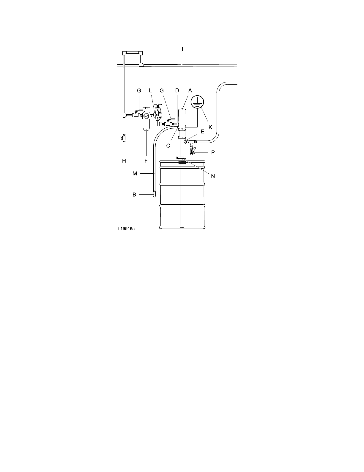
Figure 1 Typical Installation
Key
Pump Components (Included) System Components/Accessories (sold separately)
A Bung-mounted sanitary pump F
B
Air exhaust muffler (may be mounted on pump or
remotely, using exhaust hose, ref. M)
3/8 npt exhaust air outlet H Air line drain pipe and valve
C
D 3/8 npt air inlet J Main air line
E
1 in. tri-clamp flanged fluid outlet (Order Kit 24R649
for adapter to 25 mm threaded DIN 11851. See
Accessories, page 26.)
Air line filter/regulator (Graco PN 234398)
G Bleed-type master air valve (required)
K
Pump ground wire (required, Graco PN 238909)
L Pump runaway valve
M Exhaust hose, Kit 24R646, see
Accessories, page 26.
N
Sanitary bung adapter
P
Fluid drain valve (required)
8 3A2977D
Page 9
Operation
Operation
NOTICE
Do not expose the air motor to temperatures
higher than 120°F (49°C) or the immersed fluid
pump to temperatures higher than 250°F (121°C).
Excessive temperatures may damage the pump
packings and seals.
To avoid injury from exhaust hose whip, never
operate the pump without a muffler installed.
Secure the exhaust hose to a solid, stationary
object.
Pressure Relief Procedure
Follow the Pressure Relief Procedure
whenever you see this symbol.
Flush Before First Use
The sanitary
lubricant on
water. Flus
appropriat
sanitize th
Flushing Pr
and local co
pump was assembled using sanitary
moving parts and was tested in
h the pump thoroughly with an
e cleaning solution or disassemble and
e parts before using the pump. See
ocedure, page 10. Check national, state,
des for specific limitations.
Adjusting the Pump Speed and
Pressure
Set pressure regulator to 0 psi. Open the bleed-type
master air valve. Adjust the pump air regulator until
the pump is running smoothly.
Allow th
outofth
from the
With the air supply turned on, the pump will start
when the dispensing valve is opened and stall
against pressure when the valve is closed. In a
circulating system, the pump operates until the air
supply is turned off.
e pump to cycle slowly until all air is pushed
e lines (the fluid will flow in a steady stream
fluid outlet) and the pump is primed.
This equipment stays pressurized until pressure
is manually relieved. To help prevent serious
injury from pressurized fluid, such as splashing
in the eyes or on skin, follow the Pressure Relief
Procedure when you stop dispensing and before
cleaning, checking, or servicing the equipment.
1. Shut off the air supply to the pump.
2. Close the bleed-type master air valve (required
in system).
3. Open the fluid ball valve and/or dispensing valve
to relieve fluid pressure.
4. Open all fluid drain valves in the system, having
a waste container ready to catch drainage.
Leave drain valve(s) open until you are ready to
dispense again.
NOTIC
Never allow the pump to run dry of fluid. A dry
pump will accelerate to a high speed, possibly
damaging itself.
If the pump accelerates quickly, or is running too
fast, stop the pump immediately and check the fluid
supply. If the supply is empty and air has been
pumped into the lines, replace the container and
prime the pump and lines with fluid. Be sure to
eliminate all air from the system.
E
Pump Shut Down
llow the Pressure Relief Procedure, page 9 .
Fo
3A2977D 9
Page 10

Maintenance
Maintenance
Flushing Procedure
Note:
• Flush before fluid can dry in the equipment, at the
end of the day, before storing, and before repairing
equipment.
• Flush at the lowest pressure possible. Check
connectors for leaks and tighten as necessary.
• Flush with an appropriate cleaning solution.
1. Follow Pressure Relief Procedure, page 9 .
2. Remove the pump from the fluid container. Place
it in an empty drum. Operate it to pump out as
much fluid as possible.
3. Place siphon tube in grounded metal pail
containing an appropriate cleaning solution.
4. Set pump air regulator to lowest possible fluid
pressure, and start pump.
5. Run the pump long enough to thoroughly clean
thepumpandhoses.
2. Remove the pump from the fluid container. Place
it in an empty drum Operate it to pump out as
much fluid as possible.
3. Flush the system thoroughly with an
appropriate cleaning solution. See
Flushing Procedure, page 10.
4. Follow the Pressure Relief Procedure, page 9 .
5. Remove the air and fluid hoses and fittings from
the pump.
6. Disassemble the fluid pump and accessories.
See Disassemble the Pump, page 16.
7. Wash all pump parts with an appropriate cleaning
solution at the cleaning product manufacturer’s
recommended temperature and concentration.
8. Rinse all pump parts again with water and allow
them to dry.
9. Inspect all pump parts and reclean if needed.
Note
Any dama
be repl
microo
the flui
ged rubber parts must
aced as they could harbor
rganisms that can contaminate
d.
6. Follow Pressure Relief Procedure, page 9 .
Cleaning
• Be sure to follow your national and state sanitary
standard codes and local regulations.
• Use appropriate cleaning and disinfecting agents,
at intervals appropriate for product processed.
• Follow cleaning product manufacturer’s
instructions.
Note: Thepumplowermust be disassembled to
thoroughly clean it.
1. Follow the Pressure Relief Procedure, page 9 .
10. Immers
saniti
out of
11. Lubri
packi
sanit
12. Circ
and t
eallpumppartsinanappropriate
zer before assembly. Take the pump parts
the sanitizer one-by-one as needed.
cate the moving pump parts and o-rings,
ngs, and seals with appropriate waterproof
ary lubricant.
ulate the sanitizing solution through the pump
he system prior to use.
Tighten Threaded Connections
Before each use, check all hoses for wear or damage.
Replace as necessary. Check that all connections
are tight and leak-free.
10 3A2977D
Page 11

Troubleshooting
Troubleshootin
g
Problem
Pump cycles, but no fluid comes out.
Pump cycles, but fluid flow is too
slow.
Pump dives and/or does not pump
on upstroke.
on downstroke.
1. Follow Pressu
2. Check all poss
Troubleshoo
pump.
Cause Solution
Fluid supply is empty.
Air supply flow or pressure is
inadequate.
Air valves are closed or clogged.
Air line is closed or clogged. Remove obstruction.
Fluid line is obstructed. Remove obstruction.
ne is too small.
Fluid li
Fluid is too thick.
Pump rod check seat or seals are
worn out or missing.
Inlet check seat or seals are worn
out or missing.
re Relief Procedure, page 9 .
ible remedies in the
ting Chart before disassembling the
Replace fluid supply.
Improve air supply flow, increase
pressure, or increase air line size.
Open air l
Increase size of fluid line.
Reduce
diluti
Replace check seat or seals.
Replace inlet check seat or seals.Pump dives and/or does not pump
ine. Use dry air.
viscosity of fluid by heat or
on.
d inlet is obstructed.
Flui
Pump cycles unevenly or erratically. Air motor is obstructed by ice chunks
or other material.
id is too thick, causing cavitation.
Pump dives at fast speeds only.
Air motor stalls and hisses air.
Air motor hisses air while running. Air motor has a damaged o-ring or
Fluid comes out of exhaust port.
Pump rod locks up. Throat cartridge weep hole is
Cover won’t stay on.
Flu
Ice has built up in the air motor. Use dry air.
irmotorhasabrokenormissing
A
eal.
s
Air motor has a broken part. Replace broken item.
upper gasket.
Throat seals are worn or missing. Replace throat seals.
Air line contains too much water. Use dry air.
clogged.
Air motor cylinder has a leak. Tighten air motor cylinder or cover;
Clear obstructions away from inlet.
Raise pump off of drum bottom.
Remove obstruction. Use dry air.
Reduce viscosity of fluid by heat
or dilution or slow down the pump.
Raisepumpoffthebottomofthe
drum.
eplace air motor seals.
R
Replace damaged item.
Clear.
replace square cylinder seals.
3A2977D
11
Page 12

Repair
Repair
Disconnect the Air Motor
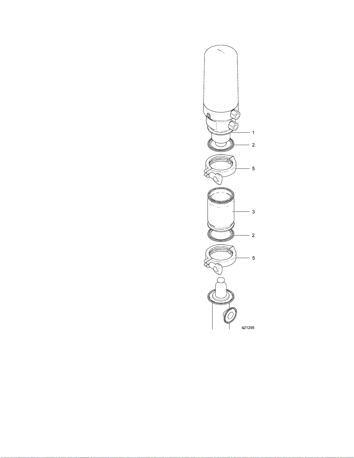
1. Follow the Pressure Relief Procedure, page 8.
2. See Figure 11, page 17.
3. Release the top clamp (5).
4. Tilt the air motor and unhook the shaft from the
displacement rod. Lift the air motor up and off
therestofthepump.
5. Release the bottom clamp (5). Remove
connector (3) and gasket (2).
6. Remove the bung adapter clamp.
7. Pull the displacement pump straight up and out
of the container.
Air Motor Disassembly
1. Use flats on the base (118) to clamp the air motor
into a vise.
2. Remove the motor cover (10).
3. Remove cap (103). Use a large channel-lock or
strap wrench on the cap and hold the cylinder
(101) with a strap wrench to prevent distortion to
the cylinder. Remove gasket (102) from inside of
the cap. Inspect the spring (104) under the cap.
NOTE: Use a screwdriver to pop out the spring
if it must be replaced.
4. Use a strap wrench to remove the cylinder (101).
Inspect for scoring or damage.
Fig
ure 2
2
1
3A2977D
Page 13

Repair
5. Air Valve Disassembly: Follow these steps to
disassemble the air valve for cleaning or parts
replacement.
a. Remove three s
the valve cap (
and spacers (1
crews (114), then remove
108). Remove gasket (107)
11).
6. Air Valve Replacement: Follow these steps to
replace the entire air valve, without disassembly.
a. Purchase Kit 2
assembly.
b. Clamp piston
with a spanne
valve (105).
between the s
the air valve
62035 to replace entire valve
in a vice. Hold the piston cap
r wrench and unscrew the air
Wedge a screwdriver blade
crew heads and the hex cap of
to turn.
Figure 3
b. Pull three o-rings (112) out the sides of the
valve. Remove o-ring (106).
gure 4
Fi
Figure
c. Remove
d. Repla
ce with the new assembled valve and
gs from Kit 262035. Use pipe sealant on
o-rin
reads of the valve (105) and torque to
the th
15 to 2
5
o-rings (115, 106).
0 ft-lbs (20.3 to 27.1 N·m).
3A2977D 13
Page 14

Repair
7. Slide the air piston (124) out of the top of the
air motor base (118). Remove o-ring (120) and
gasket (102) from inside the air motor base.
Remove o-ring (123) from groove on outside of
base. Inspect all parts, including the spring (122)
in the air motor base.
NOTE: Do not r
retainer (12
NOTE: If the white bushing (119) needs to
be replaced, use an arbor press to remove.
Alternate tapping on the edges with a hammer
andanylonrodormetalpunchalsowillwork.
The spring (122) and retainer (121) must be
removed first.
emove the spring (122) and
1)ifyoudonothaveto.
Air Motor Reassembly
Cylinder threads are sharp. Always wear protective
gloves to prevent cuts.
1. If the bushing (119) was removed, use an arbor
press and seat it all the way into the air motor
base (118). Alternate tapping using a hammer
and nylon rod or metal punch also works.
2. Install the retainer (121) into the air motor base.
Tap on the retainer as needed to ensure it seats
all the way.
3. If the spring (122) was removed, put it into the air
motor base (118), with the wider end down. Use
a screwdriver to pop it into the groove.
4. Lubricate and install o-ring (120) and gasket
(102) on the inside of the motor base. Lubricate
and install o-ring (123) on the outside.
5. Useflatstoclampthebase(118)intoavise.
6. Lubricate the shoulder and the bottom outside
portion of the piston (124). Then, lower it into the
air motor base (118).
4
1
Figure 6
3A2977D
Page 15

Repair
7. Reassemble the air valve (if needed): Lubricate
and install a new o-ring (106) on the air valve
(105). Lubricate and install the three o-rings
(112), then install the spacers (111). Install
gasket (107) and valve cap (108). Apply blue
Loctite or equivalent on the screw threads.
Torquethescrewsto20to30in-lb(2.3to3.4
N•m). Skip Step 8 and go to Step 9.
Torque to 20 to 30 in-lbs (2.3 to 3.4 N•m).
8. Install assembled air valve from kit: Lubricate
and install new o-rings (106 and 115). Use pipe
sealant on the threads of the valve (105) and
torque to 15 to 20 ft-lb (20.3 to 27.1 N•m). Use a
screwdriver as shown, if needed.
Torque to 15 to 20 ft-lb (20 to 27 N•m).
9. Grease the inside and threads of the cylinder
(101). With the base clamped in a vise, put the
cylinder (101) over the piston and screw into
place. Tighten with a strap wrench and torque to
50 to 60 in-lb (5.6 to 6.8 N•m).
10. Lubricate and install a new gasket (102) into the
air cylinder cap (103). Make sure the spring
(104) is in place. Lubricate the cylinder threads.
Use a strap wrench to tighten the cap (103) onto
the cylinder (101). Torque to 15–20 ft-lb (20.3
to 27.1 N•m).
11. Replace the cover (10).
3A2977D 15
Page 16

Repair
Disassemble the Pump
If not yet done
Disconnect th
careful not to
to the bench fo
1. Use a pick to move the o-rings (208) to the center
of the inlet seat pin (214). Slide the pin halfway
out, remove the o-rings (108), then slide the pin
the rest of the way out.
2. Use a screwdriver in the slot to remove the
inlet valve assembly. Remove the retaining pin
(212) and ball (213). Push the seat (210) out
the bottom of the inlet housing (209). Remove
o-rings (211 and 216). Clean and inspect the
parts.
, follow steps in
e Air Motor, page 12. Note: Be
scratch the displacement rod. Carry
rservice.
all the way. Then, remove the cartridge (215).
Remove o-rings (216, 220). Use a screwdriver
to push the u-cup (217) out of the center of the
cartridge. Be careful not to damage the lips.
Figure 7
3. Pull the displacement rod (202) out of the top of
the cylinder (201) a few inches, but do not remove
Figure 8
16 3A2977D
Page 17

Repair
4. Push the displacement rod (202) all the way out
the
bottom
of the cylinder.
Reassemble Af
Note: Any damaged parts must be replaced.
Note: Lubricate the o-rings, throat packings, and
piston seals with appropriate waterproof sanitary
lubricant.
1. Lubricate and install u-cup (204) and bearing
(205) on the piston seat (203). U-cup lip
face up.
the seat assembly. Install the ball (207), then the
seat assembly in the outlet housing.
2. Lubricate and install one o-ring (208) in the
groove on the outlet seat pin (206). Push the pin
(206) through the holes. Lubricate and install the
other o-ring (208) in the other groove on the pin.
Check that the o-rings (208) are seated in the
grooves.
NOTE: Be sure to use the
on the pin (206) and the
on the seat assembly. Stack the o-rings on the
bench if needed to determine size.
Lubricate and install o-rings (218) on
ter Cleaning
smaller
larger
o-rings (218)
must
o-rings (208)
Figure
5. See Fi
slide
other
ball (
seat (
etaining pin o-rings (208). Slide the bearing
the r
) and u-cup (204) off the seat (203).
(205
NOTE
remo
outer or inner lip of the u-cup.
the
6. Cle
an and inspect all parts. Replace the parts
ecessary.
as n
9
gure 10. Remove one o-ring (208), then
out the retaining pin (206) and remove the
o-ring. Remove the outlet assembly and
207). Remove the o-rings (218) from the
203). Be careful not to mix them up with
: If not replacing the u-cup (204), carefully
ve and clean the o-ring, without damaging
Figure 10
3. Lubricate the inside of the cylinder, near the
ends. Then, slide the rod (202) into the cylinder
from the top.
4. Lubricate and install a new u-cup (217) into
the cartridge (215).
U-cup lips must face out of
cartridge.
5. Lubricate and install o-ring (216) on the outside
of the cartridge (215).
6. Lift the rod (202) out of the cylinder part way.
Lubricate the rod and slide the cartridge (215)
over the rod, into the cylinder.
7. Lubricate and install o-ring (220) over the rod into
the groove in the top of the cartridge. Then push
the rod back into the cylinder.
3A2977D
17
Page 18
Repair
8. Lubricate and install o-ring (211) on inlet seat
(210), then install seat (210) in inlet housing
(209). Use the pin to align the holes.
9. Lubricate and install o-ring (216) on inlet housing
(209), then install the ball (213) and pin (212).
10. Slide the assembled housing into the bottom of
the cylinder.
11. Push the pin (214) through the holes on one side.
Lubricate and install o-rings (208)
putting one in each groove on the pin. Then slide
the pin into the second side. The ends of the pin
should be flush to the outside of the cylinder.
Check that the o-rings are seated in the grooves.
from the inside
Reconnect The Pump
,
1. Install th
2. Slide the
3. Install a
pump. The
displace
aclamp(5)handtight.
Install
4. Install
the other gasket (2) on the air motor. Be
sure it i
Hook the
and low
(5) han
e bung adapter (19) in the drum cover.
displacement pump down into the drum.
gasket (2) on the top of the displacement
n install the connector (3) on the
ment pump, with the
s securely on the alignment shoulder.
air motor shaft on the displacement rod
er the air motor into place. Install clamp
dtight.
smaller
side down.
Figure 11
18 3A2977D
Page 19

Notes
Notes
3A2977D 19
Page 20

Parts
Parts
Apply sanitary grease
before assembling cover.
20 3A2977D
Page 21

Parts
Complete Pump
Ref. Part
1
24R180* MOTOR, SaniF
2 166117
3 16U981
5
6
7
620223
24R190 Used on Pump Model
24R189 Used on Pump Model
24R192 Used on Pump Model
24R191 Used on Pump Model
112933 MUFFLER 1
Description
see Air Motor
GASKET, san
CONNECTOR
CLAMP, 2.5 i
DISPLACEM
PUMP; see
Displacem
24N300
24N344
24R046
24R047
Models 24N300, 24N344, 24R046, and 24R047
orce; 2:1,
Parts.*
itary fitting
n. Tri-clamp
ENT
ent Pump Parts.
Qty.
1
2
1
2
1
Ref. Part
10 24R178
14 16U653
17
18▲ 16T148 LABEL, warning 1
19 24R650 KIT, bung adapter, includes
19a
19b
▲ Replacement Danger and Warning labels, tags,
and cards are available at no cost.
*
-——
–——
–——
Air Motor 24R180 does not include cover (ref. 10).
Order Kit 24R179 for an air motor with cover.
Description
COVER, motor
o-ring (ref.
TOOL, pick
LABEL, compliance 1
19a and 19b
Clamp
Bung adapter
123)
;includes
Qty.
1
1
1
3A2977D
21
Page 22
Parts
Air Motor 24R1
Torque to 50 to 60 in-lb (5.6 to
6.8 N•m).
Apply sanitary lubricant.
Apply medium-strength thread
locker.
80
Torque to 15 to 20 ft-lb (20.3 to
27.1 N•m).
Torque to 20 to 30 in-lb (2.3 to
3.4 N•m).
Apply pipe sealant.
2
2
3A2977D
Page 23

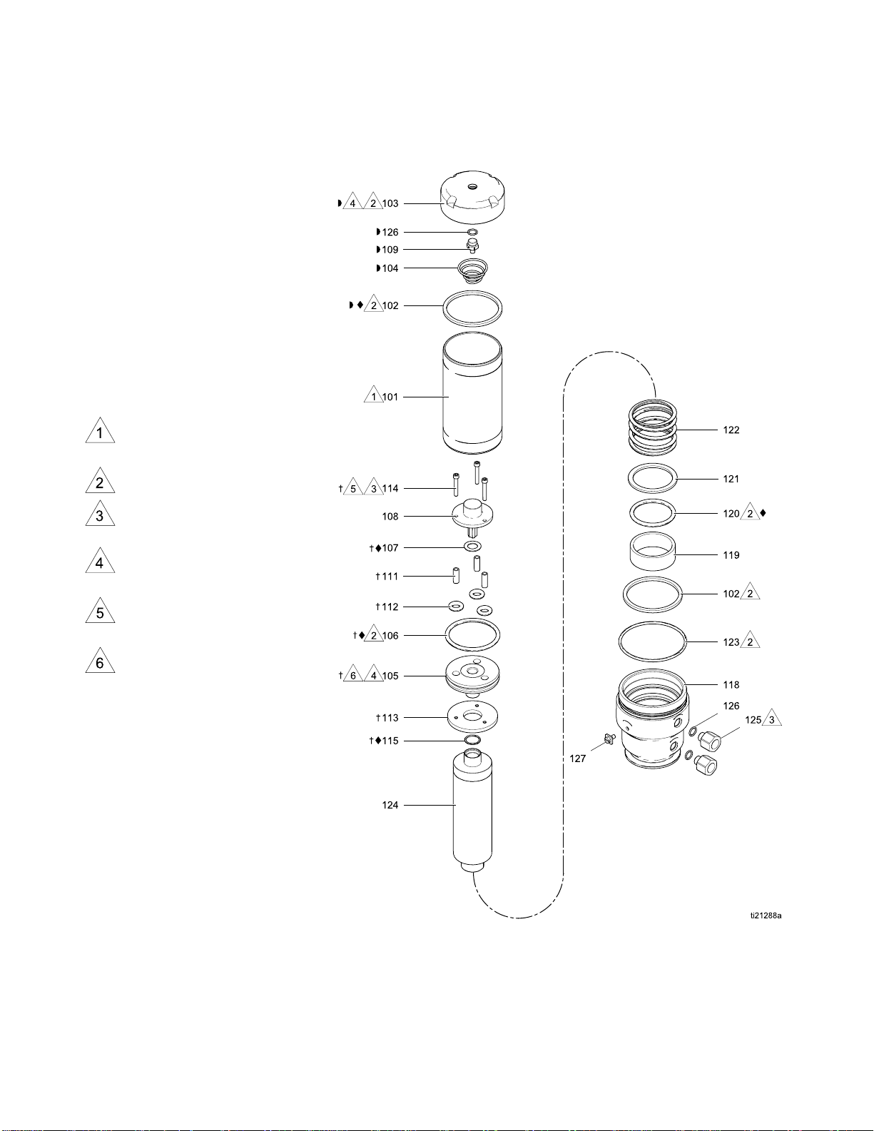
Parts
Air Motor 24R1
Ref. Part
101 16P288
102✦◗ 120212
103◗
104◗ 157630
105✝
106✦✝ 160258
107✦✝
108✝
109◗
111✝ 15J544
112✝
113✝ 15J546
114✝ 121610
115✦✝ 722834
118 16P900
119
———
———
———
———
———
———
-——
80 Parts
Description
CYLINDER, air motor
GASKET
CAP, air cylinder
SPRING, tapered
HEAD, air piston 1
O-RING, buna-N
GASKET, upper
CAP, valve
PIN, spring stop;
included with ref. 103
SPACER, disk
O-RING, buna-N
DISK, air piston
SCREW, cap, socket
head
O-RING, FKM
BASE, air motor
BUSHING, air motor;
included with air piston
assembly (ref. 124)
Qty.
Ref. Part
1
2
1
1
1
1
1
1
3
3
1
3
1
1
1
120✦ 159846
121 16P926 RETAINER, o-ring 1
122 15J551
123 U22665
124 24R176
125 24R177
126◗ 111819
127 116343
✦
Parts included in Air Motor Seal Kit 24R175.
✝
Parts included in Air Valve Kit 262035.
◗
Parts included in Air Cylinder Cap Kit 24T043.
Description
O-RING, buna-N
SPRING, compression
O-RING
PISTON, air, assembly;
includes Bushing (ref.
119) and o-ring (ref.
120)
FITTING, i
stainless
to 3/8–18 n
o-ring (r
O-RING; included with
ref. 103
SCREW, ground
nlet/outlet,
steel, 1/2–18
pt; includes
ef. 126)
Qty.
1
1
1
1
2
3
1
3A2977D 23
Page 24

Parts
Displacement
Pump Models 24R189, 24R190, 24R191, and 24R192
Apply sanitary lubricant.
4
2
3A2977D
Page 25

Displacement Pump Parts
Parts
Ref.
201
202
203 16P149
204✷
205✷ 16P150
206 16P147 PIN, ou
207 104585 BALL, stainless steel;
208✷
209
210 16P132
Part
24R193 Models 24R190
24R194 Models 24R192 and
24R183 Models 24R190 and
24R184 Models 24R
16P254 UHMWPE; Models
16P044 PTFE; Models
———
16P133
24V838 316 stainless steel
Description Qty.
CYLINDER, pump
and
24R189
24R191
ROD, displacement
24R189
192 and
24R191
SEAT, outl
with ball (
Kit 24R18
U-CUP
24R190 and 24R192
24R189 and 24R191
BEARING, piston
check
order K
sold with seat (ref.
203) in Kit 24R181.
O-RING, 008, FKM;
included in Kits
24R187, 24R188,
24R195 and 24R196
GUIDE, ball, inlet
Acetal (standard)
(heavy-duty)
AT,inlet;soldwith
SE
ll (ref. 213) and
ba
ring (ref. 211) in Kit
o-
R182
24
et; sold
ref. 207) in
1
tlet check;
it 24R195
1
1
1
1
1
1
1
10
1
1
Ref.
211✷
212 126216 PIN, dowel 1
213 103869 BALL, bearing 1
214 16P146 PIN, seat, inlet; order
215✷✓ 16P242
216✷✓
217✷✓
218✷
220✷✓
Parts included in Pump Seals Kits 24R187
✷
Part
-——
———
-——
16P255 UHMWPE; Models
16P041 PTFE; Models
-——
-——
126806 FKM; Models 24R190
124494 PTFE; Models
Description Qty.
O-RING, 125, FKM;
sold with seat (ref.
210) and ball (ref.
213) in Kit 24R182
Kit 24R195
CARTRIDGE, throat
seal
O-RING, 129, FKM
U-CUP
24R190 and 24R192
24R189 and 24R191
O-RING, FKM, #10;
included in Kits
24R187, 24R188,
24R195 and 24R196
O-RING
and 24R192
24R189 and 24R191
(UHMWPE) and 24R188 (PTFE).
✓
Parts included in Throat Seal Kits 24R185
(UHMWPE) and 24R186 (PTFE).
1
1
1
2
1
2
1
3A2977D 25
Page 26

Kits and Accesso
ries
Kits and Accessories
Replacement Parts Kits
Kit Includes
✦ 24R175, Air Motor Seals Gasket (102), o-rings (106, 115, 120), and upper
gasket (107)
✝ 262035, Air Valve Kit
✷ 24R187, UHMWPE Pump Seals Kit OR
24R188, PTFE Pump Seals Kit
✓ 24R185, UHMWPE Throat Seal Kit OR
24R186, PTFE Throat Seal Kit
◗ 24T043
24R176, Air Motor Piston Kit
24R177, Air Inlet/Outlet Fitting Kit Inlet/outlet fitting (125) and o-ring (126)
24R17
24R179, Air Motor with Cover Kit Air motor 24R180 (1) and cover (10)
24R181, Outlet Check Seat (203) and ball (207)
24R
24R195, Retainer Pins
24R196, Retainer Pin O-rings O-ring (208, qty. 20) and o–ring (218, qty. 10)
, Air Cylinder Cap Kit
8, Air Motor Cover Kit
182, Inlet Check
Piston head
(108), spac
and o-rings
Piston check bearing (205), u-cup cartridge (215),
u-cups (214, 217), and o-rings (208, 211, 216, 218,
220)
U-cup cartridge (215), u-cup (217), and o-rings (216,
220)
Cap (103
o-ring (
Piston with cap and o-ring (124, factory assembled),
bushing (119) and o-ring (120)
Cover
t (210), ball (213), and o-ring (211)
Sea
Inlet pin (214), piston pin (206) and o-rings (208, 218)
(105), upper gasket (107), valve cap
er (111), piston disk (113), screws (114),
(106, 112, 115)
), gasket (102), spring (104), pin (109), and
126)
(10) and o-ring (123)
Accessory Kits
it
K
24R646, Exhaust Hose
24R649, ISO/DIN Adapter 1 in. (25 mm) Tri-clamp to 25 mm threaded DIN
26 3A2977D
escription
D
3/8 npt, 200 psi, FDA-Compliant hose, 6 ft.
11851, with o-ring
Page 27
Dimensions
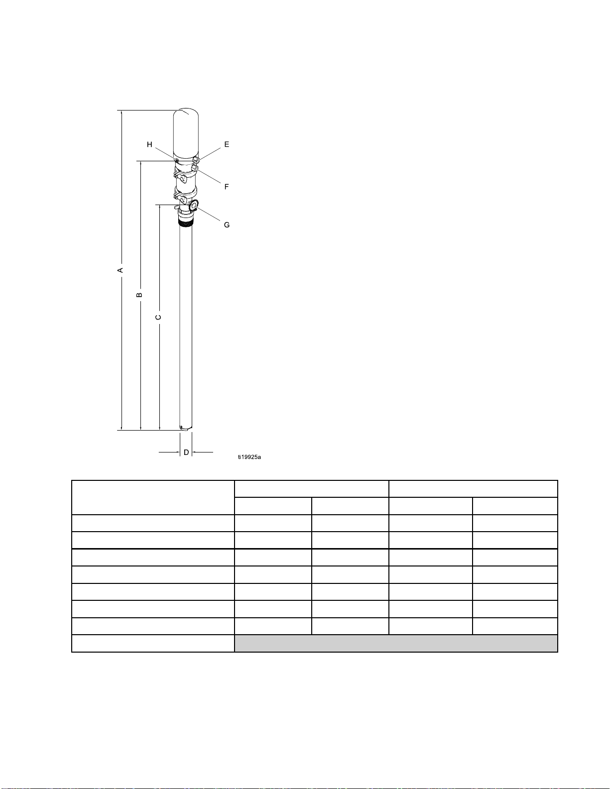
Dimensions
Model 24N300 and 24N344 Model 24R046 and 24R047
Reference in.
A 61.9 157.2 54.9 139.4
B 53.7 136.4 46.7 118.6
C
D (fluid inlet OD)
E (air inlet) 3/8 npt (f) 9.5 npt (f) 3/8 npt (f) 9.5 npt (f)
F (air exhaust) 3/8 npt (m) 9.5 npt (m) 3/8 npt (m) 9.5 npt (m)
G (fluid outlet, Tri-Clamp)
H (ground screw)
44.5 113.0 37.5 95.2
1.972 5.0 1.972 5.0
1 2.5 1 2.5
cm
in.
cm
3A2977D
27
Page 28
Performance Cha
rt
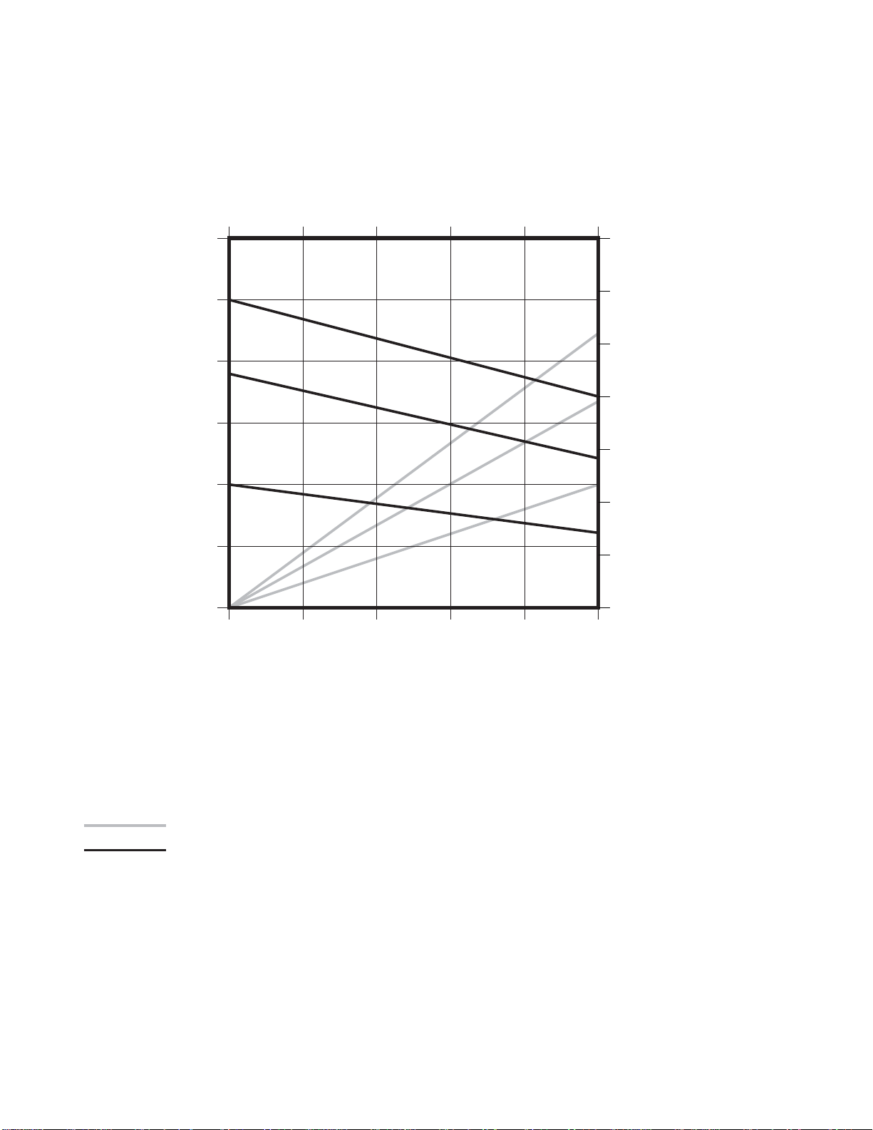
Performance C
hart
Test Conditions: Pump tested in water.
0 20 40 60 80 100
300
(2.1, 21)
250
(1.7, 17)
200
(1.4, 13)
A
B
Fluid
Outlet
Pressure
150
(1.0, 10)
psi
(MPa, bar)
100
(0.7, 7)
C
Cycles per Min
ute
14
(0.39)
12
(0.33)
A
10
(0.28)
8
B
(0.23)
Air Flow
scfm
6
(0.17)
C
4
(0.11)
(m
3
/min)
50
(0.3, 3)
00
0 0.5
(1.9)
1.0
(3.8)
Flow — gpm (lpm)
Fluid
1.5
(5.7)
KEY:
A
B
100 psi (0.7 MPa, 7 bar) Inlet Air Pressure
i (0.5 MPa, 5 bar) Inlet Air Pressure
70 ps
C 40 psi (0.3 MPa, 3 bar) Inlet Air Pressure
Air Consumption
Fluid Flow
2.0
(7.6)
2
(0.06)
2.5
(9.5)
28 3A2977D
Page 29

Technical Data
Technical Data
U.S.
Maximum Fluid Working Pressure 250 psi 17 bar, 1.7 MPa
Air Inlet Pre
Maximum Recommended Pump Speed
Pump Cycle
Ratio 2.5:1
Fluid Temperature Range
Maximum Continuous Operating Temperature 180°F 82°C
Maximum Ambient Temperature (Air Motor) 120°F 49°C
Air Inlet
Air Exhaust
Fluid Inlet Size
Cyli
InletSeatID
Fluid Outlet 1 in. Tri-clamp® 2.5 cm Tri-clamp®
nd Power*
Sou
ssure Range
s per Gallon (3.8 Liters) 40
nder OD
30 to100 psi 2.1 to 6.9 bar
MPa
100 cycles/min, 2.5 gpm
delivery
40 to 220°
3/8 npt
3/8 npt (m) 9.5 mm npt (m)
2.0 in
0.938 in 2.4 cm
73.4 at dBA at 70 psi and
20 cpm
F
(f)
100 cycles/min, 9.5
liters/min delivery
4to104°C
9.5 mm n
5cm
73.4 dBA at 4.8 bar and 20
cpm
Metric
,0.2to0.7
pt (f)
.4 at dBA at 70 psi and
Sound Pressure*
Weight
Models 24R046 and 24R047 24 lb 10.9 kg
odels 24N300 and 24N344
M
Wetted Parts
*
Sound power measured per ISO-9614–2. Sound pressure was tested 3.28 ft (1 m) from equipment.
65
cpm
20
6lb
2
300 Series Stainless Steel, Acetal, PTFE, FKM, UHMWPE
.4 dBA at 4.8 bar and 20
65
m
cp
1.8 kg
1
3A2977D 29
Page 30

Graco Standard Warranty
Graco warrants all equipment referenced in this document which is manufactured by Graco and bearing its
name to be free from defects in material and workmanship on the date of sale to the original purchaser for
use. With the exception of any special, extended, or limited warranty published by Graco, Graco will, for a
period of twelve months from the date of sale, repair or replace any part of the equipment determined
by Graco to be defective. This warranty applies only when the equipment is installed, operated and
maintained in accordance with Graco’s written recommendations.
This warranty does not cover, and Graco shall not be liable for general wear and tear, or any malfunction,
damage or wear caused by faulty installation, misapplication, abrasion, corrosion, inadequate or improper
maintenance, negligence, accident, tampering, or substitution of non-Graco component parts. Nor shall
Graco be liable for malfunction, damage or wear caused by the incompatibility of Graco equipment
with structures, accessories, equipment or materials not supplied by Graco, or the improper design,
manufacture, installation, operation or maintenance of structures, accessories, equipment or materials
not supplied by Graco.
This warranty is conditioned upon the prepaid return of the equipment claimed to be defective to an
authorized Graco distributor for verification of the claimed defect. If the claimed defect is verified, Graco
will repair or replace free of charge any defective parts. The equipment will be returned to the original
purchaser transportation prepaid. If inspection of the equipment does not disclose any defect in material
or workmanship, repairs will be made at a reasonable charge, which charges may include the costs of
parts, labor, and transportation.
THIS WARRANTY IS EXCLUSIVE, AND IS IN LIEU OF ANY OTHER WARRANTIES, EXPRESS OR
IMPLIED, INCLUDING BUT NOT LIMITED TO WARRANTY OF MERCHANTABILITY OR WARRANTY
OF FITNESS FOR A PARTICULAR PURPOSE.
Graco’s sole obligation and buyer’s sole remedy for any breach of warranty shall be as set forth above.
The buyer agrees that no other remedy (including, but not limited to, incidental or conseq
for lost profits, lost sales, injury to person or property, or any other incidental or consequential loss) shall
be available. Any action for breach of warranty must be brought within two (2) years of the date of sale.
GRACO MAKES NO WARRANTY, AND DISCLAIMS ALL IMPLIED WARRANTIES OF
MERCHANTABILITY AND FITNESS FOR A PARTICULAR PURPOSE, IN CONNECTION WITH
ACCESSORIES, EQUIPMENT, MATERIALS OR COMPONENTS SOLD BUT NOT MANUFACTURED BY
GRACO. These items sold, but not manufactured by Graco (such as electric motors, switches, hose, etc.),
are subject to the warranty, if any, of their manufacturer. Graco will provide purchaser with reasonable
assistance in making any claim for breach of these warranties.
In no event will Graco be liable for indirect, incidental, special or consequential damages resulting from
Graco supplying equipment hereunder, or the furnishing, performance, or use of any products or other
goods sold hereto, whether due to a breach of contract, breach of warranty, the negligence of Graco, or
otherwise.
FOR GRACO CA
The Parties acknowledge that they have required that the present document, as well as all documents,
notices and legal proceedings entered into, given or instituted pursuant hereto or relating directly or
indirectly hereto, be drawn up in English. Les parties reconnaissent avoir convenu que la rédaction du
présente document sera en Anglais, ainsi que tous documents, avis et procédures judiciaires exécutés,
donnés ou intentés, à la suite de ou en rapport, directement ou indirectement, avec les procédures
concernées.
NADA CUSTOMERS
uential damages
Graco Information
For the latest information about Graco products, visit www.graco.com.
For patent information, see www.graco.com/patents.
To place an order, contact your Graco Distributor or call to identify the nearest distributor.
Phone: 612-623-6921 or Toll Free: 1-800-328-0211 Fax: 612-378-3505
All written and visual data contained in this document reflects the latest product information available at the time of publication.
Graco reserves the right to make changes at any time without notice.
Original Instructions. This manual contains English. MM 3A2977
International Offices: Belgium, China, Japan, Korea
GRACO INC. AND SUBSIDIARIES • P.O. BOX 1441 • MINNEAPOLIS MN 55440-1441 • USA
Copyright 2013, Graco Inc. All Graco manufacturing locations are registered to ISO 9001.
Graco Headquarters: Minneapolis
www.graco.com
Revision D, July 2014
 Loading...