

Page 1
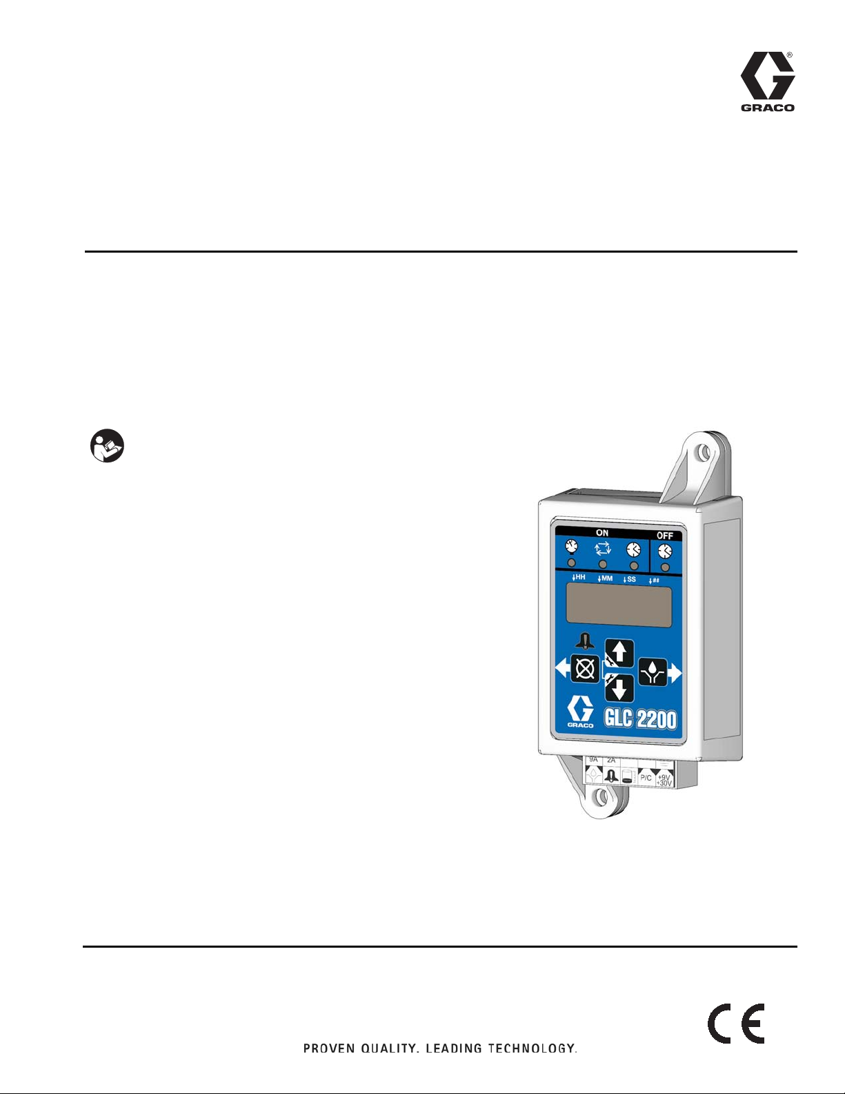
Instructions
GLC 2200
Lubrication Controller
3A2960D
For controlling and monitoring an automated lubrication system.
Not approved for outdoor use or use in explosive atmospheres or hazardous locations.
Model: 24N468
Important Safety Instructions
Read all warnings and instructions in this
manual. Save these instructions.
EN
Page 2
Warnings
WARNINGWARNINGWARNING
WARNING
Warnings
The following warnings are for the setup, use, grounding, maintenance, and repair of this equipment. The exclamation point symbol alerts you to a general warning and the hazard symbols refer to Procedure-specific risks. When
these symbols appear in the body of this manual or on warning labels, refer back to these Warnings. Product-specific
hazard symbols and warnings not covered in this section may appear throughout the body of this manual where
applicable.
EQUIPMENT MISUSE HAZARD
Misuse can cause death or serious injury.
• Do not operate the unit when fatigued or under the influence of drugs or alcohol.
• Do not exceed the maximum working Pressure or temperature rating of the lowest rated system com-
ponent. See Technical Data in all equipment manuals.
• Use fluids and solvents that are compatible with equipment wetted parts. See Technical Data in all
equipment manuals. Read fluid and solvent manufacturer’s warnings. For complete information about
your material, request MSDS from distributor or retailer.
• Do not leave the work area while equipment is energized or under pressure.
• Turn off all equipment and follow the Pressure Relief Procedure when equipment is not in use.
• Check equipment daily. Repair or replace worn or damaged parts immediately with genuine manufacturer’s replacement parts only.
• Do not alter or modify equipment. Alterations or modifications may void agency approvals and create
safety hazards.
• Make sure all equipment is rated and approved for the environment in which you are using it.
• Use equipment only for its intended purpose. Call your distributor for information.
• Route hoses and cables away from traffic areas, sharp edges, moving parts, and hot surfaces.
• Do not kink or over bend hoses or use hoses to pull equipment.
• Keep children and animals away from work area.
• Comply with all applicable safety regulations.
2 3A2960D
Page 3
Component Identification
ON
OFF
HH MM
SS
##
!
J
D
F
A
B
C
E
H
G
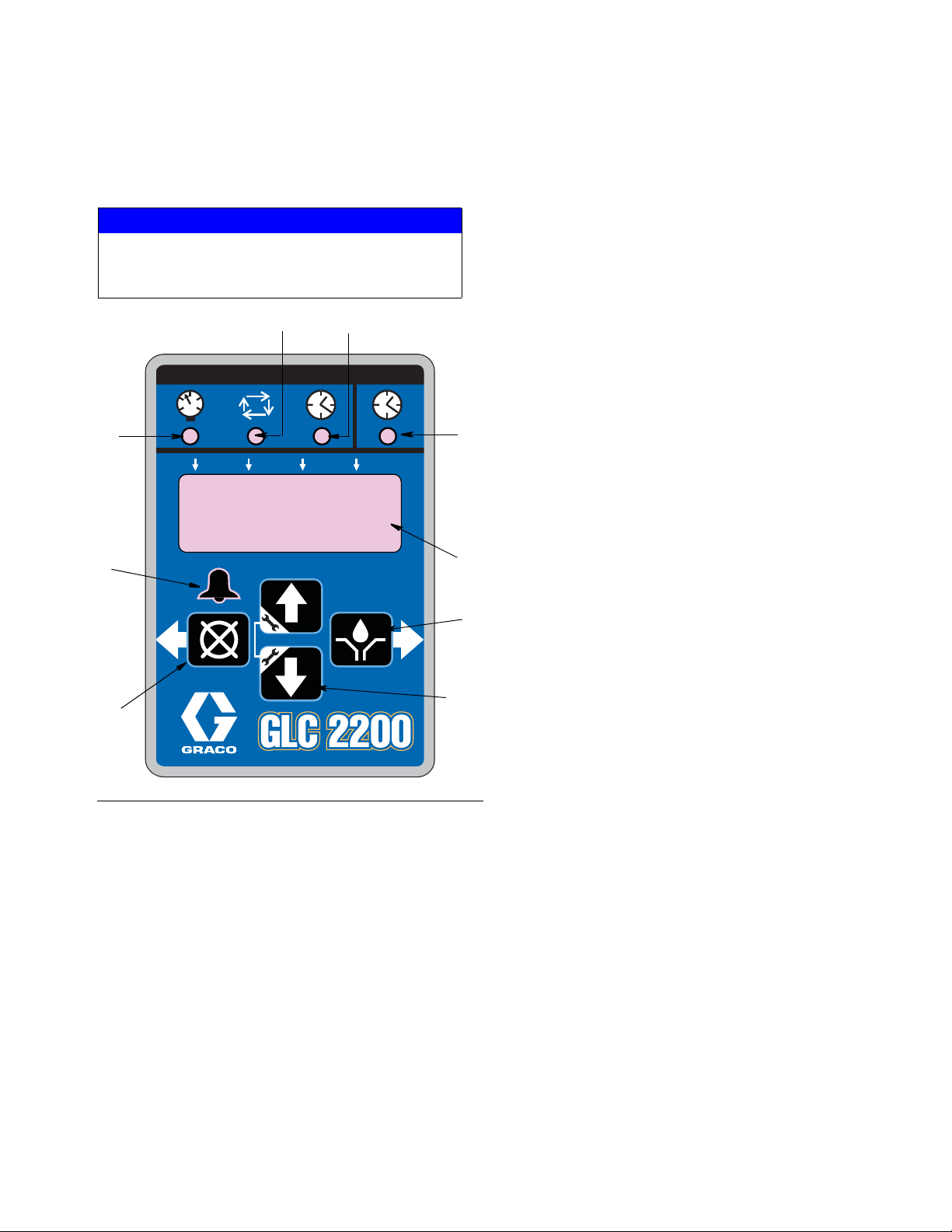
Keypad, Display, and Icons
Component Identification
NOTICE
To prevent damage to soft key buttons, do not press
the buttons with sharp objects such as pens, plastic
cards, or fingernails.
Display (E)
• A blinking field on the display indicates the controller
is in SETUP MODE.
• In RUN MODE numbers on the display will not blink.
Alarm LED (F)
Illuminates when any alarm is detected. When an alarm
is active an error code displays and an audible alarm
also sounds.
RIGHT Direction Arrow / MANUAL RUN /
ENTER (G)
• In SETUP MODE, saves entry, moves cursor in
display one field to the right or to the next setup
step.
• In RUN MODE activates the pump for one com-
plete ON cycle if actuated during the OFF portion of the RUN cycle.
UP and DOWN Direction Arrows (H)
• Press and hold both the UP and DOWN Arrow
keys together for 3 seconds to enter SETUP
MODE.
• In SETUP MODE increase or decrease number
FIG. 1
Pump ON LEDs (A, B, C)
A Pressure Control LED: In RUN MODE illuminates
indicating function mode that is currently running.
B Cycle Control LED: In RUN MODE illuminates
C Time Control LED: In RUN MODE illuminates
indicating function mode that is currently running.
indicating function mode that is currently running.
Pump OFF LED (D)
• In RUN MODE this LED illuminates when in the
OFF or RESET portion of the RUN CYCLE.
LEFT Direction Arrow / RESET (J)
values associated with the various RUN
MODES.
• In SETUP MODE moves cursor in display one
field to the left.
• In RUN MODE, Pressing RESET starts a PUMP
OFF cycle.
• In ALARM MODE, Press once to clear buzzer;
Press and hold for 3 seconds to clear warning
and switch controller to OFF MODE.
3A2960D 3
Page 4
Installation
Controller
Capabilities
B1
B2
B3
C
E
H
G
F
D
Low Reservoir Level
switch (user provided)
Pressure or Cycle Switch
for system control
(user provided)
Remote Alarm Device
i.e., light or horn
(user provided)
A
K
J
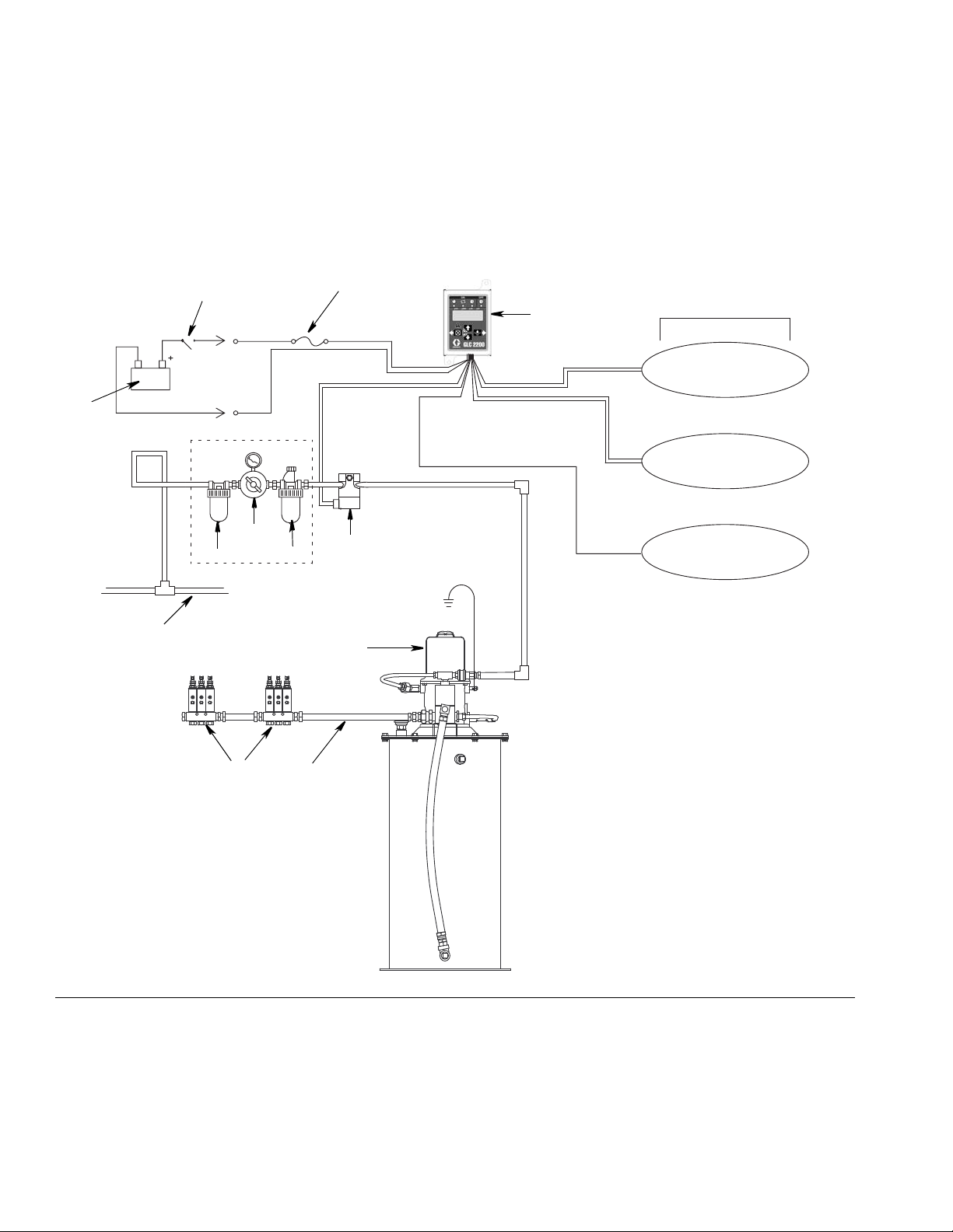
Installation
Typical Installation
The installation shown in FIG. 2 is only a guide for selecting and installing system components. Contact your Graco
distributor for assistance in planning a system to suit your needs.
FIG. 2
A Main Air Supply
B Filter/Regulator/Lubricator Assembly
B1 - Filter
B2 - Regulator
B3 - Lubricator
C Air Solenoid Valve
D Pump Module
4 3A2960D
E Ignition Switch
F High-Pressure Lubricant Supply Lines
G Injector Banks
H Lubrication Controller
J In-line Fuse
K Power Source
Page 5
Installation
a
a
Installing the Lubrication Controller
AUTOMATIC SYSTEM ACTIVATION HAZARD
Unexpected activation of the system could result in serious injury, including skin injection and amputation.
This device has an automatic timer that activates the
pump lubrication system when power is connected or
when exiting the programming function. Before you
install or remove the Lubrication Controller from the
system, disconnect and isolate all power supplies and
relieve all pressure.
1. Select a flat surface to install the Lubrication Controller. Drill mounting holes. Refer to Mounting Hole
Layout Provided in the Technical Data section of this
manual, page 20.
2. Align junction box with predrilled holes (F
Use two screws (not provided) to secure junction
box to mounting surface.
IG. 3, (a).
System Configuration and Wiring
The System Configuration Diagrams (FIG. 4 - FIG. 6),
Sensor Wiring Diagrams (F
grams (F
Injector, Series Progressive and Dual Line lubrication
system configurations.
Refer to Table 1, 2 and 3 to determine the Required System Configuration, Sensor Configuration and Wiring
Diagram to use to setup your system.
IG. 7) on the following pages, show typical
Table 1: System Configurations
System Figure Page
Injector 4 6
Series Progressive 5 7
Dual Line 6 8
Table 2: Sensor Wiring Configurations
Sensor Figure Page
Dry Contact 7 10
Source Switch 8 10
IG. 8 - FIG. 9) and Wiring Dia-
FIG. 3
Table 3: Modes of Operation
Mode Power Figure Page
Time ON/Time OFF DC 9 9
Cycle ON or Pressure
ON/Time OFF
Low Level Switch
DC 9 9
99
3A2960D 5
Page 6
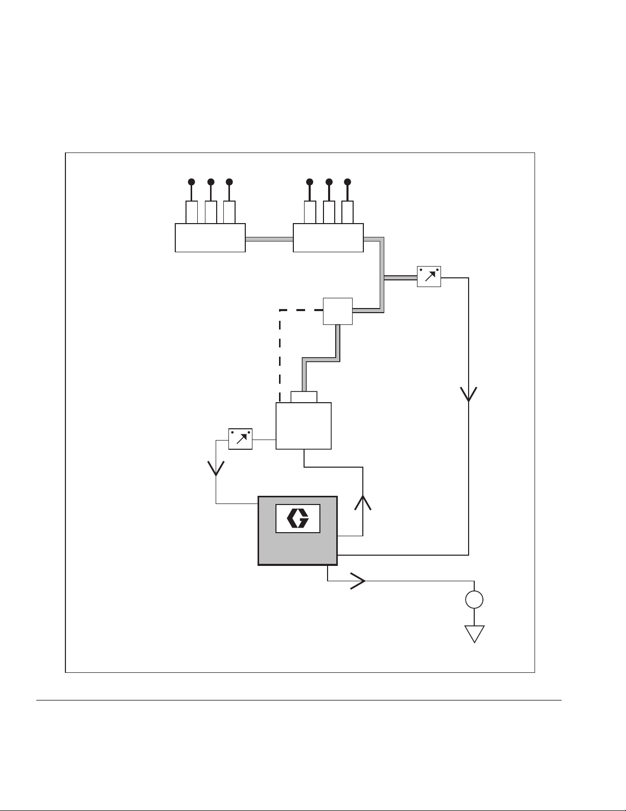
Installation
GLC 2200
Low Level
Switch
Pump &
Reservoir
Injector System
Pressure
Switch
Injectors
Lubrication Points
Vent
Line
Pump On/Off
External
Alarm
Vent
Valve
System Configuration
FIG. 4
6 3A2960D
Page 7
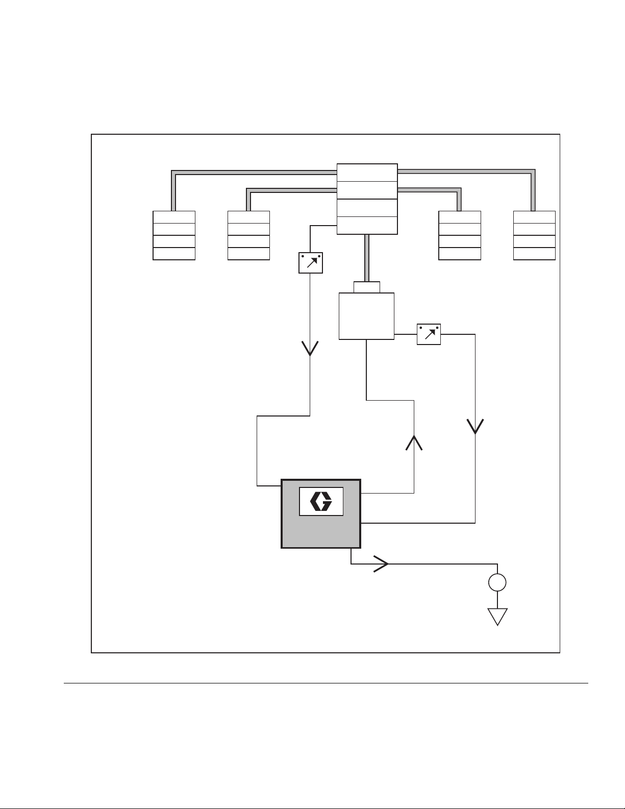
GLC 2200
Low Level
Switch
Pump &
Reservoir
Master Divider Valve
Secondary Divider Valves
Cycle
Switch
Divider Valve System
Pump On/Off
External
Alarm
Installation
FIG. 5
3A2960D 7
Page 8

Installation
GLC 2200
External
Alarm
Low Level
Switch
Pump &
Reservoir
Dual Line System
Cycle
Switch
Bi-flo
Valves
Lubrication Points
Vent
Line
Pump On/Off
Reverser
FIG. 6
8 3A2960D
Page 9

Wiring Diagram
1 2 3 4 5
6 7 8 9 10
M
9A Fuse
+
-
V
*
9A 2A
P/C
+9V
+30V
Modes of Operation: Optional I/O Wiring Diagram
Used with all modes of GLC2200 Operation
Installation
FIG. 7
*Normally open vent valve for use with Injector-based systems
Wiring Key Connector Identification Label
PIN12345
PIN678910
Pin Description
1Pump
2Alarm
3Low Level
4 Pressure/Cycle Switch
5 Voltage Input
6Pump
7Alarm
8Low Level
9 Pressure/Cycle Switch
10 Voltage Input
+/-
-
-
-
-
+
+
+
+
+
3A2960D 9
Page 10

Installation
4
9
GLC 2200
4
+VDC
-VDC
GLC 2200
Sensor Wiring Configurations
DRY CONTACT SWITCH SOURCE SWITCH - 2 or 3 Wire Type
FIG. 8
FIG. 9
10 3A2960D
Page 11

Setup
Setup
Entering SETUP MODE
1. Press both the UP and DOWN ARROW buttons
together for three seconds.
NOTE:
• If a button is not pushed for 1 minute, the controller
returns to the start of an OFF cycle.
• Setting changes are not stored unless programming
is completed and setup mode is exited normally by
pressing the ENTER button.
• A blinking dot below the HH, MM, SS, or ## indicates the field currently being programmed.
Programming ON Duration
• on:Pr, on:CY or on:ti appears on the display identi-
fying the function you are programming (see below).
• The illuminated LED below the related symbol on
the controller label also indicates the function.
Pressure Control (on:Pr) ON Setup
1. Use the UP or DOWN ARROW
until on:Pr displays.
2. Press the ENTER button.
3. Pressure control is an ON / OFF
selection only. After you press the ENTER button,
the controller saves the Pressure Control information and moves to setting Backup Time, page 12.
Cycle Control (on:CY) ON Setup
1. Use the UP or DOWN ARROW
until on:CY displays.
NOTE: Selection on:Pr, on:CY or on:ti designates
the way the pump run time is controlled:
• on:Pr = Pressure Control,
reaching a specific pressure
threshold measured by an
external pressure switch
• on:CY = Cycle Control, com-
pleting a specific number of
cycles of an external
prox/cycle switch
• on:ti = Time Control, a spe-
cific duration of time elapses
2. Press the ENTER button.
The first number displayed after the
on:CY is entered, blinks, indicating the device is ready
to program the number of cycles.
NOTE: The cycle entry is a 2-digit number. A leading
zero (0) must be entered in the first field if the number of
cycles is fewer than 10.
3. Program the cycles by pressing the UP or DOWN
ARROW to move up or down through the numbers
0-9.
4. When the correct first digit is displayed, press the
ENTER button.
3A2960D 11
Page 12

Setup
The cursor automatically moves to the second number
field and flashes.
Use the UP or DOWN ARROW to scroll through the
numerals 0-9 until the desired number appears in the
second cycle number field.
5. Press the ENTER button. After you press the
ENTER button, the controller saves the Cycle Control information and moves to setting Backup Time,
page 12.
Time Control (on:ti) ON Setup
1. Use the UP or DOWN ARROW to
cycle through until on:ti displays.
2. Press ENTER.
NOTE:
• The Seconds (SS) field is a 2-digit number.
• A leading zero (0) must be entered in the first
field if the number of seconds is fewer than 10.
• The highest number that can be set for the SS
field value is 59.
7. Repeat steps 3 - 6 to set the SS fields.
8. Press the ENTER button. After you press the
ENTER button the controller automatically switches
to the OFF TIME SETUP MODE.
Backup Time
In both Cycle and Pressure Modes, a maximum run
Time (Backup Time) for the lubrication period must be
set up. If this Time expires before the lubrication is completed an alarm/warning is triggered and the pump
stops.
To determine the Backup Time, Graco recommends the
user verify the length of time it takes to complete a typical cycle and double that value.
Backup Time is setup after Cycle or Pressure Sensor
Setup is complete.
3. To set the ON time use the UP or
DOWN ARROW to scroll through
the numerals 0-5 until the desired number appears
in the first Minutes (MM) field.
NOTE:
• The MM field is a 2-digit number.
• A leading zero (0) must be entered in the first
field if the number of minutes is fewer than 10.
• The highest number that can be set for the MM
field value is 59.
4. Press the ENTER button.
The next MM number field to the right flashes, indicating
it is ready for programming.
5. Use the UP or DOWN ARROW to scroll through the
numerals 0-9 until the desired number appears in
the second MM number field.
6. Press the ENTER button.
The next number field to the right flashes indicating it is
ready to program the Seconds (SS) fields.
NOTE:
• The LED below the clock in the ON field
lights, indicating the Backup Time is being
programmed.
• BACKUP (ON) Time is set as minutes and seconds
(MM:SS) only.
• The small flashing LED under the MM indicates you
are setting minutes.
• The first field (left side of display) blinks indicating
the device is ready for you to begin programming.
Programming Backup Time
NOTE: When programming a time of less than 10 min-
utes you must program the leading zero in the first num-
ber field and press the ENTER button.
12 3A2960D
Page 13

Setup
OFF
1. To set the ON Time use the UP or
DOWN ARROW button to scroll through
numerals 0 to 5 until the desired number
appears in the first MM (minutes) field.
2. Press the ENTER button. The next
MM number field to the right flashes
indicating it is ready for programming.
3. Use the UP or DOWN ARROW button to
scroll through numerals 0 to 9 until the
desired number appears in the second
MM number field.
4. Press the ENTER button.
The next number field to the right
flashes and the LED lights under SS;
indicating it is ready to program the seconds fields.
5. Repeat steps 1 - 4 to set the SS (seconds) fields.
6. After pressing the ENTER button to
set the last SS field, all the programmed ON Time information is
saved.
To set the OFF Time:
1. Use the UP or DOWN ARROW to
scroll through the numerals 0-9
until the desired number appears
in the first Hours (HH) field.
2. Press ENTER.
The next HH number field to the right
flashes, indicating it is ready for programming.
3. Use the UP or DOWN ARROW to scroll through the
numerals 0-9 until the desired number appears in
the second HH field.
4. Press the ENTER button.
The next number field to the right flashes indicating it is
ready to program the Minutes (MM) fields.
NOTE:
• The MM field is a 2-digit number.
• A leading zero (0) must be entered in the first
field if the number of minutes is fewer than 10.
• The highest number that can be set for the MM
field value is 59.
The controller automatically switches to the OFF
Time SETUP MODE.
Programming OFF TIME Duration
After setting the parameters for either Pressure (Pr),
Cycle (CY) or Time (Ti) ON Modes, the OFF TIME or
PUMP REST CYCLE must be set up.
The LED below the OFF TIME Symbol Illuminates.
NOTE:
• The HH field is a 2-digit number.
• A leading zero (0) must be entered
in the first field if the number of
hours is fewer than 10.
• The highest number that can be set for the HH
field value is 99.
3A2960D 13
5. Repeat steps 1 - 4 to set the MM fields.
6. Press the ENTER button to lock in the last MM field.
The controller automatically switches to the LOW
LEVEL SETUP MODE.
Programming the Low Level Setting
NOTE: If LOW LEVEL is not used (i.e., Low Level inputs
are not connected), configuring the Low Level Setting is
still required. The unit’s default settings can be used.
LL:01 displays. This is the default low
level setup when working with a standard, normally open, low level switch.
The unit will enter a low level fault condition after the
switch input is closed for more than 1 second when the
unit is in the ON portion of the RUN MODE.
Page 14

Setup
1. Use the UP or DOWN ARROW
until LL:02 displays. This will set
the controller up to use a "paddle-style" low level algorithm (like
the Graco G3 grease units). To
ensure a low level condition has
been met in this mode, 10 consecutive low level triggers must be
detected. If a low level trigger is
not detected in 30 seconds of run
mode, the count is reset to zero.
2. Press the ENTER button.
NOTE: When the user exits SETUP
MODE:
• An alarm sounds briefly and LED lights indicating
the new programming settings and OFF TIME information are saved.
• The display shows the revision level.
• The controller goes to the beginning of a PUMP
OFF Cycle.
Operation
Run Mode
The controller is in Run Mode providing the following circumstances are present:
• The controller is not in SETUP MODE.
• An Alarm is not active.
Pressure Mode: Pump ON
The display indicates the amount of backup time
remaining (see Pressure Mode (on:Pr) ON setup, page
12).
• The Pressure ON LED illuminates and the pump
output is enabled as long as the system is in the
Pump ON state.
• If the pressure switch input is activated before the
Backup Pump On Time expires, the system
switches to a Pump OFF state.
• If the pressure switch is NOT activated before the
Backup Pump On Time expires the system faults,
goes to the Pump OFF state and pauses until the
alarm is cleared.
• Pump ON time is shown in MM:SS (minutes:seconds)
Pressure Mode: Pump OFF
The display indicates the amount of time remaining in
the pump OFF cycle, counting down the Pump OFF time
value (see Programming OFF Time Duration, page 12).
• The pump output is disabled during the Pump OFF
time.
• The Time OFF LED is illuminated as long as the
system is in the Pump OFF state.
• Pump OFF time is shown in HH:MM (hours:minutes)
or MM:SS if the time remaining is less than an hour.
14 3A2960D
Page 15

Setup
Cycle Mode: Pump ON
The display alternates between the number of cycles
remaining and indicates the amount of time remaining in
the pump cycle, counting down the Backup Pump ON
time value (see Cycle Mode (on:CY) ON Setup, page
11).
• The Cycle ON LED illuminates and the pump output
is enabled as long as the system is in the Pump ON
state.
• If the Input Cycle Switch is activated the amount of
times equal to the Cycle Definition variable before
the Backup Pump On Time expires, the system
switches to a Pump OFF state.
• If the cycle switch is NOT activated the number of
times equal to the cycle definition variable before
the Backup Pump On Time expires the system
faults, goes to the Pump OFF state and pauses until
the Alarm is cleared.
• Pump ON time is shown in MM:SS (minutes:seconds)
Cycle Mode: Pump OFF
The display indicates the amount of time remaining in
the pump OFF cycle, counting down the Pump OFF time
value (see Programming OFF Time Duration, page 12).
• The pump output is disabled during the Pump OFF
time.
Timer Mode: Pump OFF
The display indicates the amount of time remaining in
the pump OFF cycle, counting down the Pump OFF time
value (see Programming OFF Time Duration, page 12).
• The Time OFF LED illuminates and the pump output
is disabled during the Pump OFF time.
• Pump OFF time is shown in HH:MM (hours:minutes)
or MM:SS if the time remaining is less than an hour.
Alarm Operation
When an alarm situation occurs:
• pump operation is immediately
disabled,
• the front panel Alarm LED illuminates,
• an error code displays
• an audible alarm sounds
• the alarm output contact activates
Press the Reset button once to clear
buzzer; press and hold for 3 seconds
to clear alarm and switch controller to
OFF MODE.
See Alarm Types and Messages Table, page 16 for
additional information related to alarms and alarm messages.
• The Time OFF LED illuminates as long as the system is in the Pump OFF state.
• Pump OFF time is shown in HH:MM (hours:minutes)
or MM:SS if the time remaining is less than an hour.
Timer Mode: Pump ON
The display indicates the amount of time remaining in
the pump cycle, counting down the Pump ON time value
(see Time Control (on:ti) ON Setup, page 12).
• The Pump output is enabled.
• Pump ON time is shown in MM:SS (minutes:seconds).
3A2960D 15
Page 16

Setup
Alarm Types and Messages
Alarm Type Error Code Description Things to Check/Do
Refill lubrication reservoir.
Low Level Low lubricant level
Backup time expired prior to
Cycle
Pressure
receiving programmed
number of cycle counts
Backup time expired prior to
receiving pressure switch
input.
If low level fault occurs unexpectedly verify wiring
and programming setup.
Inspect lubrication system for broken or plugged
lines.
Confirm pump is operating correctly.
Inspect wiring and switch.
Confirm that sufficient backup time was
programmed for environment conditions (e.g.,
slower system response in cold temperatures)
Verify programming.
Inspect lubrication system for broken or plugged
lines.
Confirm pump is operating correctly.
Confirm vent valve is operating correctly.
Inspect wiring and switch.
Confirm that sufficient backup time was
programmed for environment conditions (e.g.,
slower system response in cold temperatures).
Verify programming.
Cycle power.
System Fault
16 3A2960D
Internal system error
occurred.
If the system error persists contact Graco
Customer Support.
Page 17

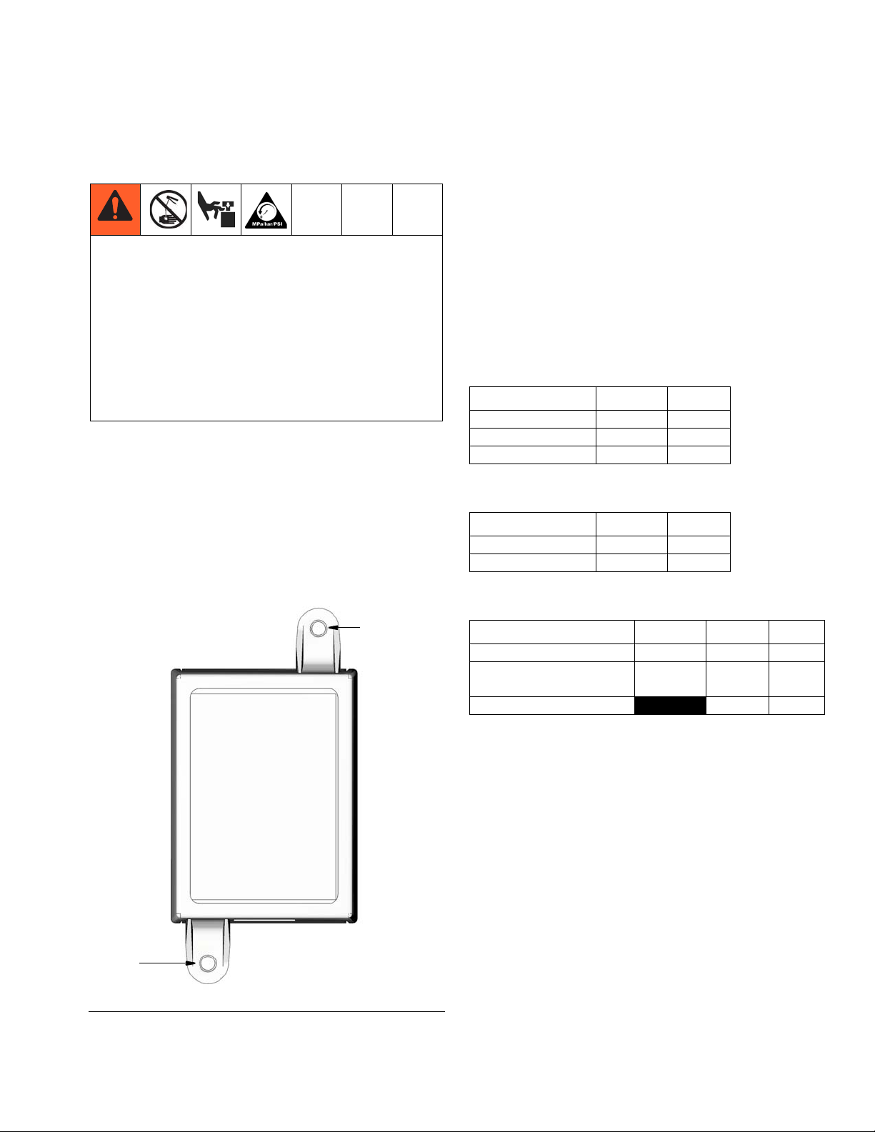
Parts
1
3
4
2
Ref. Description Qty
1 BOX, enclosure 1
2 LABEL, control, overlay 1
3 LABEL, serial, name 1
4 LABEL, connector 1
Parts
3A2960D 17
Page 18

Troubleshooting
Troubleshooting
Description Problem Solution
Unit does not power on or display is
dim/unresponsive
Program Settings
Description
Incorrect or loose wiring
Input voltage is out of range Confirm power source is between 9
Tripped external fuse Confirm that none of the devices or
Modes of Operation
Maximum / Minimum and Additional Comments
Refer to installation instructions
beginning on page 4.
and 30 VDC.
wiring connected to the controller are
causing a short circuit connection.
Replace fuse. If fuse trips again, contact Graco Customer Support.
PUMP ON, page 11 Pressure, Cycle, Time
PRESSURE CONTROL, page 11 MM:SS (00:01 - 59:59)
CYCLE CONTROL Setup, page 11 Cycles = 01 - 99
BACKUP TIME Setup, 12 MM:SS (00:01 - 59:59)
TIME CONTROL, page 12 MM:SS (00:01 - 59:59)
Time
PUMP OFF Setup, page 13
Pump OFF Time: HH:MM (00:01 - 99:59)
LOW LEVEL, page 13 LL:01 = Default single activation
LL:02 = “Paddle Style” - 10 count activation
Accessories
Related Kits
Kit No. Description
24P314 GLC2200 Wiring Harness Kit
24P686 Single Connector Kit
24P687 Multiple Connector Kit
18 3A2960D
Page 19

Technical Data
Technical Data
Input Contact
Power Source DC 9 - 30 VDC
Power Consumption 1 Watt
Cycle/Pressure Control Input (optional) 9 - 30 VDC, Normally open Pressure or cycle switch
Lubrication level (optional) Normally open level switch, closes upon low level
Outputs
Pump control Pump Control Voltage = Power Source
Voltage Pump Control Voltage = Power Source
Max Switching Voltage 30 VDC
Max Switching Current 9A (DC)
Min Switching Current 100 mA (DC)
Alarm, normally open
Voltage Alarm = Power Source
Max Switching Voltage 30 VDC
Max Switching Current 2A (DC)
Protection grade
Alarm Sound Pressure Level
Enclosure Material
Membrane Material
Maximum Humidity
Operating temperature range - 40°F to 176°F (- 40°C to 80°C)
Storage Temperature - 40°F to 176°F (- 40°C to 80°C)
IP54 for indoors and vehicle cab use
75 dB
ABS
Polyester
90% RH (non-condensing)
3A2960D 19
Page 20

Dimensions
2.75 in. (70.0 mm)
5.53 in.
(140.0 mm)
1.38 in.
(35.0 mm)
1.57 in.
(40.0 mm)
4.92 in.
(125.0 mm)
2 x Ø
0.2 in.
(5.0 mm)-
Dimensions Mounting Hole Layout
20 3A2960D
Page 21

Notes
Notes
3A2960D 21
Page 22

Graco Standard Warranty
Graco warrants all equipment referenced in this document which is manufactured by Graco and bearing its name to be free from defects in
material and workmanship on the date of sale to the original purchaser for use. With the exception of any special, extended, or limited warranty
published by Graco, Graco will, for a period of twelve months from the date of sale, repair or replace any part of the equipment determined by
Graco to be defective. This warranty applies only when the equipment is installed, operated and maintained in accordance with Graco’s written
recommendations.
This warranty does not cover, and Graco shall not be liable for general wear and tear, or any malfunction, damage or wear caused by faulty
installation, misapplication, abrasion, corrosion, inadequate or improper maintenance, negligence, accident, tampering, or substitution of
non-Graco component parts. Nor shall Graco be liable for malfunction, damage or wear caused by the incompatibility of Graco equipment with
structures, accessories, equipment or materials not supplied by Graco, or the improper design, manufacture, installation, operation or
maintenance of structures, accessories, equipment or materials not supplied by Graco.
This warranty is conditioned upon the prepaid return of the equipment claimed to be defective to an authorized Graco distributor for verification of
the claimed defect. If the claimed defect is verified, Graco will repair or replace free of charge any defective parts. The equipment will be returned
to the original purchaser transportation prepaid. If inspection of the equipment does not disclose any defect in material or workmanship, repairs will
be made at a reasonable charge, which charges may include the costs of parts, labor, and transportation.
THIS WARRANTY IS EXCLUSIVE, AND IS IN LIEU OF ANY OTHER WARRANTIES, EXPRESS OR IMPLIED, INCLUDING BUT NOT LIMITED
TO WARRANTY OF MERCHANTABILITY OR WARRANTY OF FITNESS FOR A PARTICULAR PURPOSE.
Graco’s sole obligation and buyer’s sole remedy for any breach of warranty shall be as set forth above. The buyer agrees that no other remedy
(including, but not limited to, incidental or consequential damages for lost profits, lost sales, injury to person or property, or any other incidental or
consequential loss) shall be available. Any action for breach of warranty must be brought within two (2) years of the date of sale.
GRACO MAKES NO WARRANTY, AND DISCLAIMS ALL IMPLIED WARRANTIES OF MERCHANTABILITY AND FITNESS FOR A
PARTICULAR PURPOSE, IN CONNECTION WITH ACCESSORIES, EQUIPMENT, MATERIALS OR COMPONENTS SOLD BUT NOT
MANUFACTURED BY GRACO. These items sold, but not manufactured by Graco (such as electric motors, switches, hose, etc.), are subject to
the warranty, if any, of their manufacturer. Graco will provide purchaser with reasonable assistance in making any claim for breach of these
warranties.
In no event will Graco be liable for indirect, incidental, special or consequential damages resulting from Graco supplying equipment hereunder, or
the furnishing, performance, or use of any products or other goods sold hereto, whether due to a breach of contract, breach of warranty, the
negligence of Graco, or otherwise.
FOR GRACO CANADA CUSTOMERS
The Parties acknowledge that they have required that the present document, as well as all documents, notices and legal proceedings entered into,
given or instituted pursuant hereto or relating directly or indirectly hereto, be drawn up in English. Les parties reconnaissent avoir convenu que la
rédaction du présente document sera en Anglais, ainsi que tous documents, avis et procédures judiciaires exécutés, donnés ou intentés, à la suite
de ou en rapport, directement ou indirectement, avec les procédures concernées.
Graco Information
TO PLACE AN ORDER, contact your Graco distributor or call to identify the nearest distributor.
Phone: 612-623-6928 or Toll Free: 1-800-533-9655, Fax: 612-378-3590
All written and visual data contained in this document reflects the latest product information available at the time of publication.
GRACO INC. AND SUBSIDIARIES • P.O. BOX 1441 • MINNEAPOLIS MN 55440-1441 • USA
Copyright 2012, Graco Inc. All Graco manufacturing locations are registered to ISO 9001.
Graco reserves the right to make changes at any time without notice.
For patent information, see www.graco.com/patents.
Original instructions. This manual contains English. MM3A2960
Graco Headquarters: Minneapolis
International Offices: Belgium, China, Japan, Korea
www.graco.com
December 2013
 Loading...