

Page 1
Instructions - Parts
®
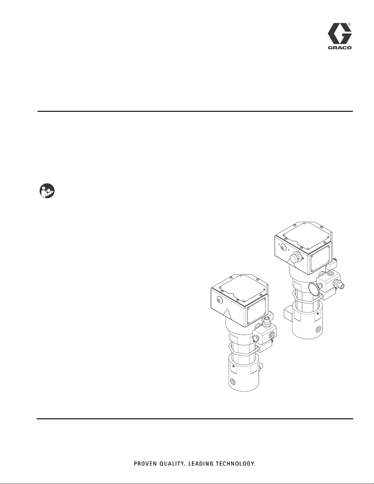
VISCON
High Flow, High Pressure Fluid Heater
For variable heating of viscous fluids.
Not approved for use in explosive atmospheres or hazardous locations.
7250 psi (50 MPa, 500 bar) Maximum Working Pressure
Important Safety Instructions
Read all warnings and instructions in this manual.
Save these instructions.
HF
3A2954D
EN
See page 2 for model numbers, descriptions, and approvals
information.
Externally Controlled, RTD
Feedback Model
Thermostat
Controlled
ti20051a
Page 2
Models
Contents
Models ...................................2
Warnings .................................3
Installation ................................ 5
TypicalInstallationDrawing ................ 5
Component Identification ....................6
General Information ...................... 7
SelectingTubing .........................7
Mounting Heater .........................8
Fluid Connections and Accessories ..........9
Electrical Connections ...................10
RTD Temperature Connection .............10
Grounding ............................. 10
Operation ................................11
Pressure Relief Procedure ................11
Initial Flushing .........................11
Priming System .........................11
Setting Heater Control ...................12
AdjustingforSpraying .................... 12
Maintenance ..............................13
Flushing ..............................13
Drain the Heater ........................ 13
Troubleshooting ...........................14
Repair ...................................16
Primary Thermostat & Probe ...............16
Overtemperature Switch ..................16
Control Knob ...........................18
Heater Core Removal and Fluid Passage
Unclogging .........................19
Heater Cartridges .......................20
RTD Sensor and Fitting Replacement ........21
Parts ....................................22
24P016 ...............................22
262853 ...............................24
Accessories ..............................26
TechnicalData ............................27
Performance Charts .....................28
Dimensions ............................29
Graco Standard Warranty ...................30
GracoInformation .........................30
Models
VAC (50/60 Hz single phase) /
Model Series Description
24P016 C Thermostat Control 240 / 5400 / 22.5
262853 C
RTD, For Use With
External Digital Control
Watts / Amps
240 / 5400 / 22.5
Approvals
9902471
Conforms to
UL Std. 499
CSA Std. 22.2 No. 88
2 3A2954D
Page 3
Warnings
Warnings
The following warnings are for the setup, use, grounding, maintenance, and repair of this equipment. The exclamation point symbol alerts you to a general warning and the hazard symbols refer to procedure-specific risks. When
these symbols appear in the body of this manual or on warning labels, refer back to these Warnings. Product-specific
hazard symbols and warnings not covered in this section may appear throughout the body of this manual where
applicable.
WARNING
ELECTRIC SHOCK HAZARD
This equipment must be grounded. Improper grounding, setup, or usage of the system can cause electric
shock.
• Turn off and disconnect power at main switch before disconnecting any cables and before servicing
or installing equipment.
• Connect only to grounded power source.
• All electrical wiring must be done by a qualified electrician and comply with all local codes and
regulations.
BURN HAZARD
Equipment surfaces and fluid that’s heated can become very hot during operation. To avoid severe burns:
• Do not touch hot fluid or equipment.
SKIN INJECTION HAZARD
High-pressure fluid from gun, hose leaks, or ruptured components will pierce skin. This may look like just
a cut, but it is a serious injury that can result in amputation. Get immediate surgical treatment.
• Do not spray without tip guard and trigger guard installed.
• Engage trigger lock when not spraying.
• Do not point gun at anyone or at any part of the body.
• Do not put your hand over the spray tip.
• Do not stop or deflect leaks with your hand, body, glove, or rag.
• Follow the Pressure Relief Procedure when you stop spraying and before cleaning, checking, or
servicing equipment.
• Tighten all fluid connections before operating the equipment.
• Check hoses and couplings daily. Replace worn or damaged parts immediately.
FIRE AND EXPLOSION HAZARD
Flammable fumes, such as solvent and paint fumes, in work area can ignite or explode. To help prevent
fire and explosion:
• Use equipment only in well ventilated area.
• Eliminate all ignition sources; such as pilot lights, cigarettes, portable electric lamps, and plastic drop
cloths (potential static arc).
• Keep work area free of debris, including solvent, rags and gasoline.
• Do not plug or unplug power cords, or turn power or light switches on or off when flammable fumes
are present.
• Ground all equipment in the work area. See Grounding instructions.
• Use only grounded hoses.
• Hold gun firmly to side of grounded pail when triggering into pail. Do not use pail liners unless they
are antistatic or conductive.
• Stop operation immediately if static sparking occurs or you feel a shock. Do not use equipment
until you identify and correct the problem.
• Keep a working fire extinguisher in the work area.
3A2954D 3
Page 4
Warnings
WARNING
TOXIC FLUID OR FUMES HAZARD
Toxic fluids or fumes can cause serious injury or death if splashed in the eyes or on skin, inhaled, or swallowed.
• Read MSDSs to know the specific hazards of the fluids you are using.
• Store hazardous fluid in approved containers, and dispose of it according to applicable guidelines.
PERSONAL PROTECTIVE EQUIPMENT
Wear appropriate protective equipment when in the work area to help prevent serious injury, including
eye injury, hearing loss, inhalation of toxic fumes, and burns. This protective equipment includes but is not
limited to:
• Protective eyewear, and hearing protection.
• Respirators, protective clothing, and gloves as recommended by the fluid and solvent manufacturer
EQUIPMENT MISUSE HAZARD
Misuse can cause death or serious injury.
• Do not operate the unit when fatigued or under the influence of drugs or alcohol.
• Do not exceed the maximum working pressure or temperature rating of the lowest rated system
component. See Technical Data in all equipment manuals.
• Use fluids and solvents that are compatible with equipment wetted parts. See Technical Data in all
equipment manuals. Read fluid and solvent manufacturer’s warnings. For complete information about
your material, request MSDS from distributor or retailer.
• Do not leave the work area while equipment is energized or under pressure.
• Turn off all equipment and follow the Pressure Relief Procedure when equipment is not in use.
• Check equipment daily. Repair or replace worn or damaged parts immediately with genuine manufacturer’s replacement parts only.
• Do not alter or modify equipment. Alterations or modifications may void agency approvals and create
safety hazards.
• Make sure all equipment is rated and approved for the environment in which you are using it.
• Use equipment only for its intended purpose. Call your distributor for information.
• Route hoses and cables away from traffic areas, sharp edges, moving parts, and hot surfaces.
• Do not kink or over bend hoses or use hoses to pull equipment.
• Keep children and animals away from work area.
• Comply with all applicable safety regulations.
PRESSURIZED ALUMINUM PARTS HAZARD
Use of fluids that are incompatible with aluminum in pressurized equipment can cause serious chemical
reaction and equipment rupture. Failure to follow this warning can result in death, serious injury, or property damage.
• Do not use 1,1,1-trichloroethane, methylene chloride, other halogenated hydrocarbon solvents or
fluids containing such solvents.
• Many other fluids may contain chemicals that can react with aluminum. Contact your material supplier for compatibility.
THERMAL EXPANSION HAZARD
Fluids subjected to heat in confined spaces, including hoses, can create a rapid rise in pressure due to
the thermal expansion. Over-pressurization can result in equipment rupture and serious injury.
• Open a valve to relieve the fluid expansion during heating.
• Replace hoses proactively at regular intervals based on your operating conditions.
4 3A2954D
Page 5
Installation
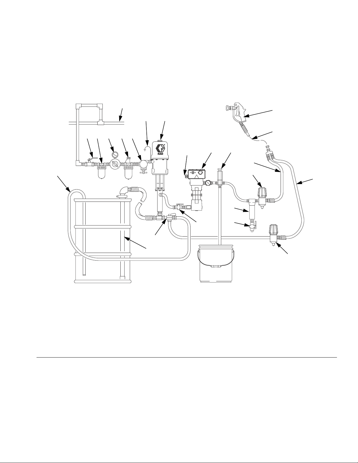
Typical Installation Drawing
The typical installation drawing is only a guide. Your Graco distributor can assist in designing your system.
Installation
Z
Q
GF
Y
EDCBA
J
XK
P
V
N
R
L
T
M
U
W
S
05486-524
Key:
A Bleed-type Master Air Valve
B Air Filter
C Air Regulator and Gauge
D Air Line Lubricator
E Pump Runaway Valve
F Ground Wire
G Pump
J Power Cable (not shown)
K Heater
L Fluid Filter
M Drain Valve
N Fluid Pressure Regulator
P Fluid Supply Line
Q Spray Gun
R Fluid Return Line
S Back Pressure Valve
T Fluid Shutoff Valve
U Director Valve
V Drain Back Tube
W Suction Tube
X Pressure Relief Valve
Y Whip End Hose
Z Air Supply Line
FIG. 1: Typical Installation – Heated Circulating System
3A2954D 5
Page 6
Component Identification
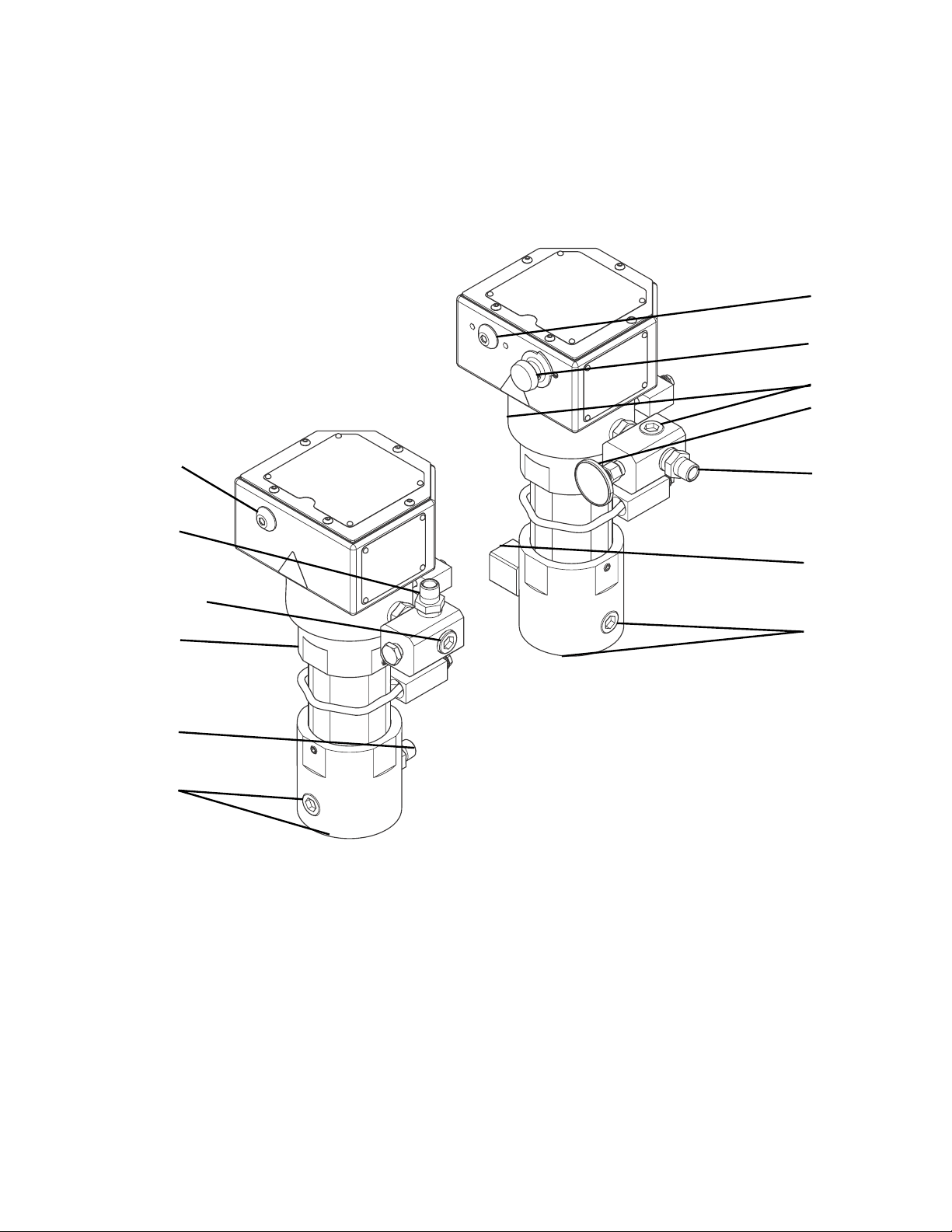
Component Identification
Thermostat
Controlled Model
A3
A4
A3
A2
A6, A8
A8
A1
A7
Externally Controlled, RTD
Feedback Model
A8
A5
A2
A1
A7
ti20051a
Key:
A1 Fluid Inlet
A2 Fluid Outlet
A3 Heater ON Indicator Light
A4 Temperature Control Knob (24P016 Only)
A5 Temperature Gauge (24P016 Only)
A6 Optional External RTD Feedback Port (262853 Only)
A7 Optional Inlet Ports (front and bottom)
A8 Optional Outlet Ports (one on outlet manifold and one on
opposite side of heater)
6 3A2954D
Page 7
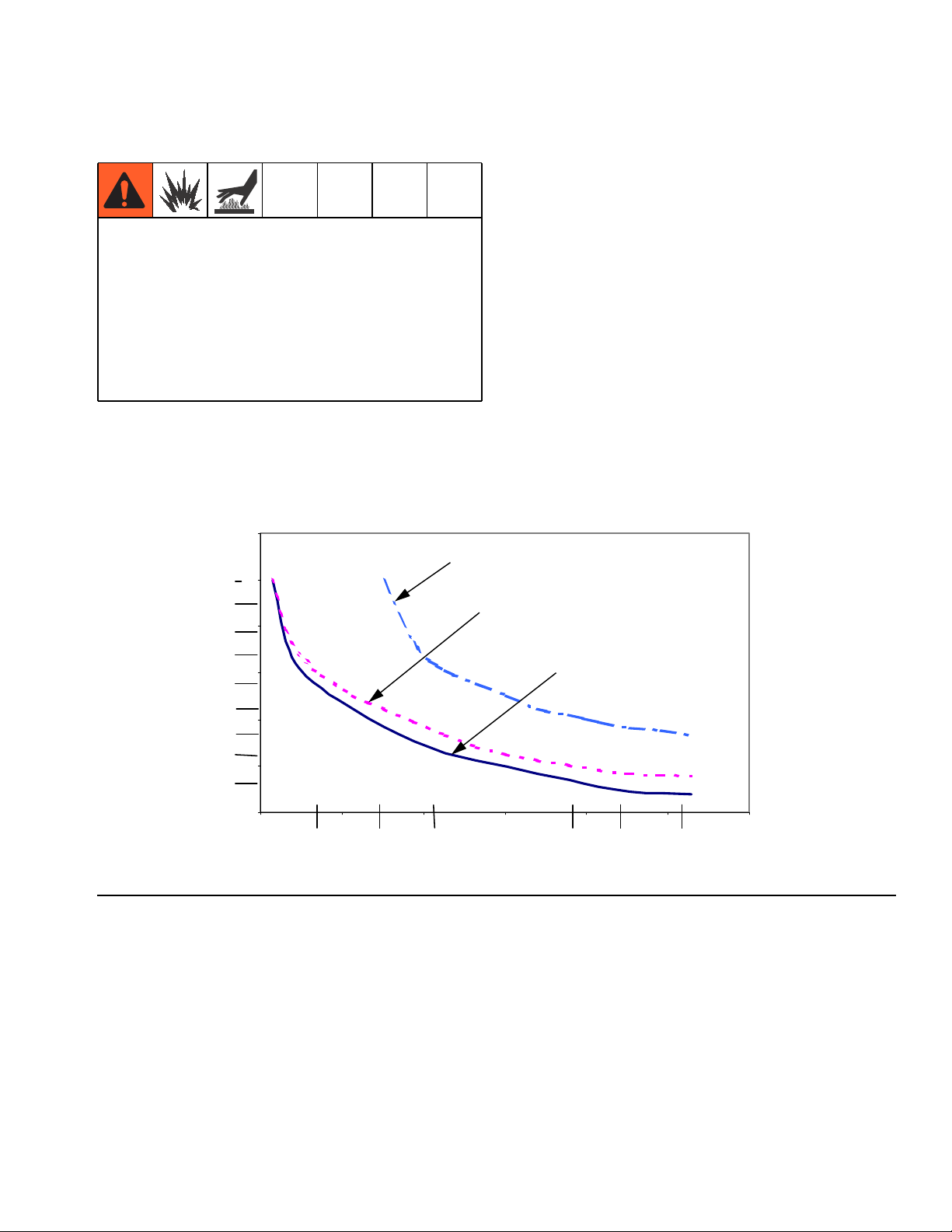
General Information Selecting Tubing
Fluid loses some heat through the tubing or hose
between the heater and spray gun. Locate heater close
to the spray area to minimize heat loss through plumb-
• Select system components that meet temperature
and pressure ratings listed in Technical Data,
page 27. The heater’s normal output range is
adjustable from 84-220°F (29-104°C).
• To prevent fire and explosion, locate heater away
from all flammable materials and where operators
will not come in contact with hot metal surfaces.
• To avoid burns, insulate and/or label lines and
components exiting heater that may become hot.
Heat Loss Curve: 70°F (21°C) Ambient
(°F) °C
6
5
(9)
(8)
4
(7)
(6)
3
(5)
(20 ft.) 6.1 m steel tube
Fluid: (130° F) 54° C
ing.
The chart in FIG. 2 shows a heat loss curve for 3 common types of tubing.
Chart Notes:
• Higher flow rates have less heat loss.
• Foam-insulated steel tubing and high pressure airless paint hose retain heat best. Insulated tubing
and hose are more expensive, but higher costs are
commonly offset by lower operating costs.
(20 ft.) 6.1 m steel tube
(3/8 in.) 9 mm foam insulation
Fluid: (110° F) 43° C
(20 ft.) 6.1 m airless paint hose
Fluid: (110° F) 43° C
Component Identification
(4)
2
(3)
(2)
Typical Fluid Temperature Drop
1
(1)
0
0 0 .5 1 1.5 2 2 .5 3
(0.1) (0.2) (0.3) (0.4) (0.5) (0.6) (0.7) (0.8)
FIG. 2: Typical Temperature Drop
LPM
(GPM)
Flow Rate
3A2954D 7
Page 8
Component Identification
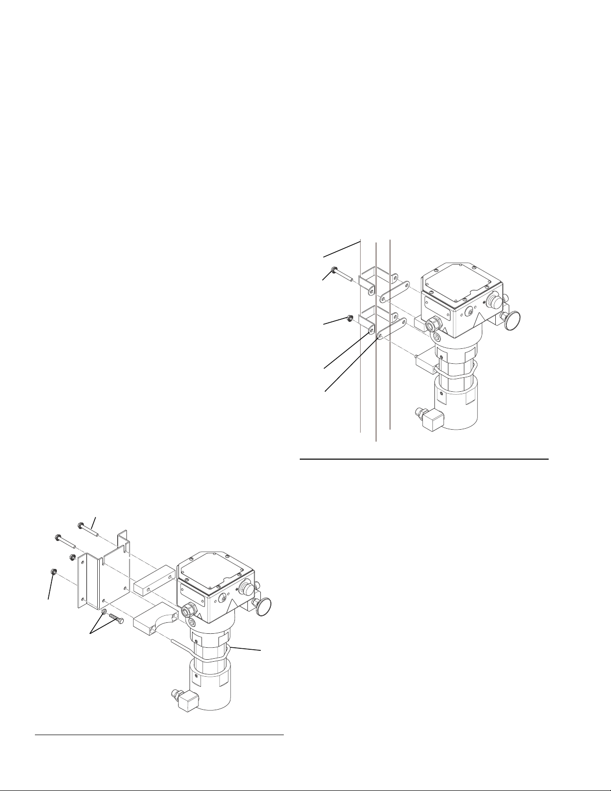
Mounting Heater
NOTE: The Viscon HF heaters will mount anywhere a
Viscon HP heater was previously mounted. See the
dimensions listed for accessory bracket 192585 on
page 26 and the heater dimensions shown on page 29.
NOTE: Heater controls must be easily accessible.
NOTE: The mounting surface must be able to support
the weight of the heater and fluid and any stress caused
during operation.
Wall Mounting
NOTE: Use wall bracket as a template to mark bolt
holes.
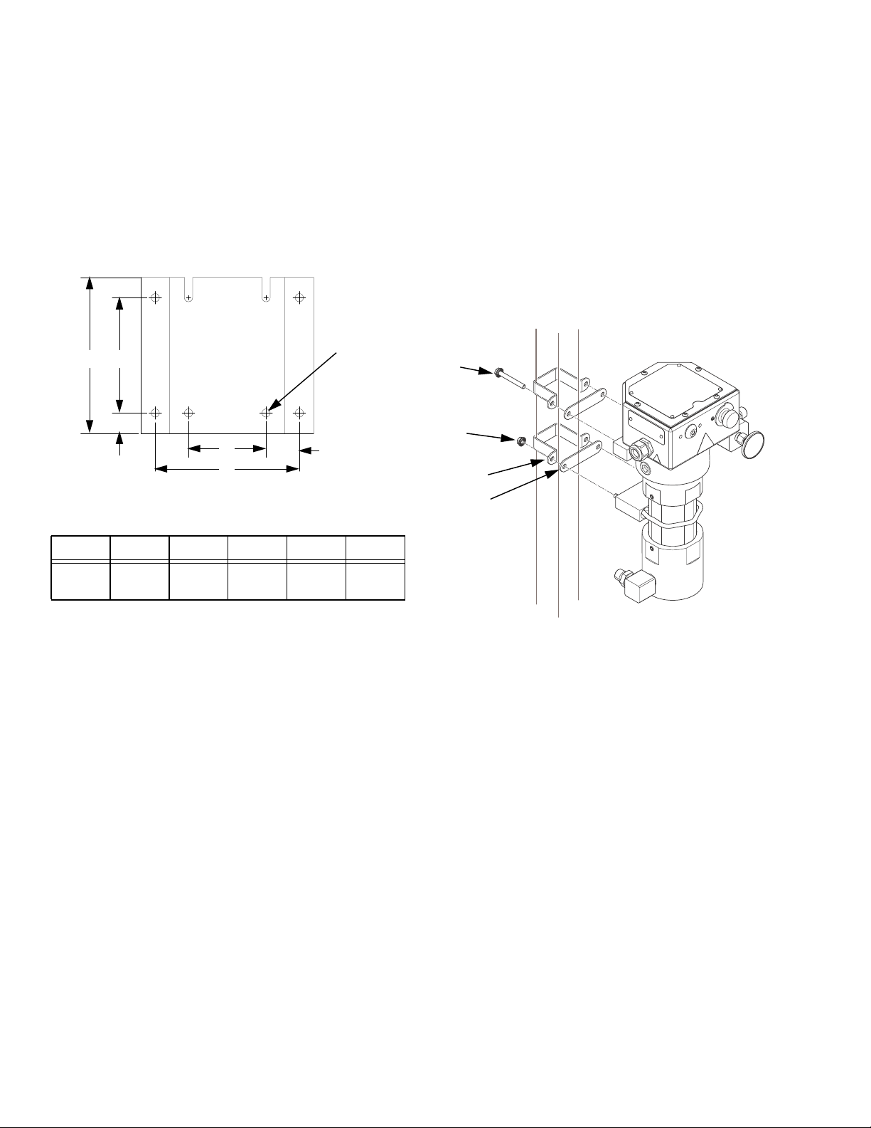
Accessory Bracket 192585
(FIG.3)
1. Use lockwashers and M8 bolts (AA) of appropriate
length, not supplied, to mount bracket.
2. Install two screws (74) through spacer block and
into top two heater mounting holes until they are
about 1/8 in. (3 mm) from fully installed.
3. Lift heater and slide two screw heads into bracket
slots.
4. Install u-bracket (78) around heater and install
remaining 2 nuts (90). Tighten all nuts and bolts.
Cart Mounting
(FIG.4)
NOTE: For a 2.5 in. square tube frame cart you need to
have 2 each of cart mounting bar 183485 (CC) and
clamp 183484 (BB). See Accessories, page 26, to
order.
Place clamps (BB) around the cart vertical post (DD)
and secure to the heater mounting bars (CC) with bolts
(74) and nuts (90).
DD
74
90
BB
CC
ti20055a
FIG.4
74
90
AA
FIG. 3: Accessory Bracket 192585
8 3A2954D
78
ti20054a
Page 9
Component Identification
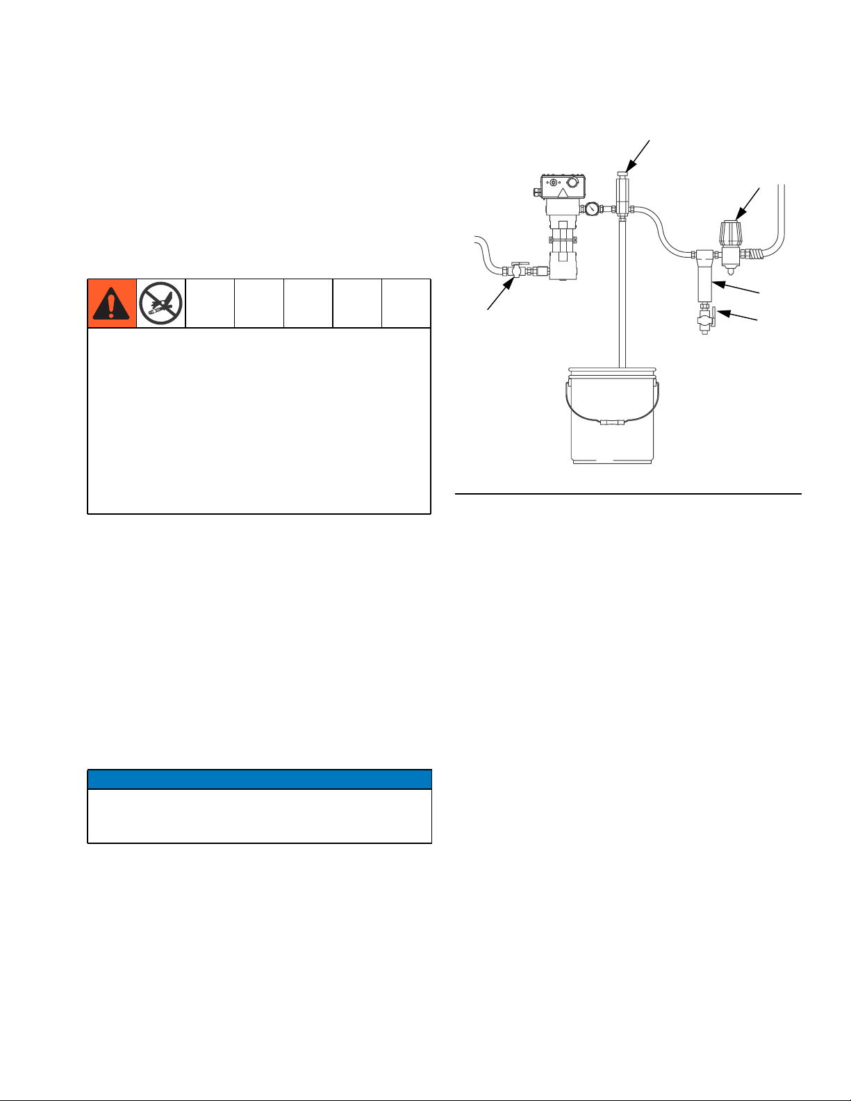
Fluid Connections and Accessories
(FIG.5)
1. Install a fluid shutoff valve (T) in the heater’s
3/4 in. npt(m) fluid inlet. Do not overtighten. Connect
the fluid supply line to the valve.
To prevent serious injury caused by component or
equipment rupture:
• Never install a shutoff device between the heater
and gun as this will trap the heated fluid and not
allow for expansion.
• Never use a fluid regulator as a shutoff device if it
is installed between the heater and gun
• Provide a means for adequately handling fluid
expansion caused by heat.
X
T
FIG. 5: Fluid Connections and Accessories
N
L
M
ti20056a
To handle fluid expansion caused by heat:
• Use flexible hoses between heater and gun.
• Install a properly sized accumulator down-
stream from the heater.
• Install a pressure relief valve (X) pre-set to
relieve pressure when it exceeds the system
maximum working pressure.
2. If feeding an airless spray gun, install a fluid
filter (L), drain valve (M), and fluid pressure regulator (N) near the heater’s 3/4-14 npt(f) fluid outlet.
Then connect the fluid outlet line.
NOTICE
The RTD sensor must always be mounted on the outlet side of housing (67). If you plumb the outlet to the
left side, swap position of sensor (88) and plug (82).
3A2954D 9
Page 10
Component Identification
Electrical Connections
Heater installation must be in compliance with all
applicable local codes and regulations. This equipment must be grounded. Improper grounding, setup,
or usage of the system can cause electric shock. All
electrical wiring must be done by a qualified electrician and comply with all local codes and regulations.
NOTICE
To help prevent damage, avoid spilling liquids onto
electrical components and never operate with the
cover removed or screws missing.
Requirements For All Installations
• The power supply must not exceed heater voltage
and amperage. See Models, page 2.
• Conductors used for supply connection must be
suitable for at least 221°F (105°C). An intermediate
Type “e” junction may be required.
Grounding
The equipment must be grounded to reduce the risk
of static sparking and electric shock. Electric or static
sparking can cause fumes to ignite or explode.
Improper grounding can cause electric shock.
Grounding provides an escape wire for the electric
current.
Wire the heater to a properly grounded power supply
through the electrical connections and grounding
screw (8). In a mobile installation, also ground the truck
or trailer to a true earth ground.
• Branch circuit breaker over-current protection must
be used. The recommended branch circuit breaker
size is 30 amps.
• Connections are made through the strain relief cord
grip (87). It will accept cords with an outside diameter of 0.51-0.71 in. (13-18 mm).
• Make your ground connection to the green ground
lug inside the control head.
• Make your power connections to the single white
and black wires which have loose ends in the control
head. Refer to the applicable schematic on page 15.
RTD Temperature Connection
(Model 262853 Only)
A separate smaller cord grip is provided to bring a cable
and connector into the M8 4-pin connection inside the
heater. Refer to the applicable schematic on page 15
and the Technical Data on page 27.
10 3A2954D
Page 11

Operation
Operation
Pressure Relief Procedure
Follow the Pressure Relief Procedure whenever
you see this symbol.
This equipment stays pressurized until pressure is
manually relieved. To help prevent serious injury from
pressurized fluid, such as skin injection, splashing
fluid and moving parts, follow the Pressure Relief
Procedure when you stop spraying and before
cleaning, checking, or servicing the equipment.
Follow Pressure Relief Procedure when you stop
spraying, and before cleaning, checking, or servicing
equipment.
1. Engage the gun trigger lock.
2. Shut off main power to the heater.
3. Circulate fluid for at least 10 minutes to cool the
heated fluid and heater.
Initial Flushing
To avoid skin injection, do not point gun at anyone or
at any part of the body. To avoid fire and explosion,
ensure main power is off and heater is cool before
flushing. Do not turn on heater until fluid lines are
clear of solvent.
The heater was tested with lightweight oil, which needs
to be flushed out before using the equipment. Use a
compatible solvent, and follow flushing instructions in
your fluid supply and spray gun manual.
Priming System
(Refer to FIG.1,page5)
1. Do not turn on the heater yet.
2. If using an airless spray gun, do not install a spray
tip yet.
4. Shut off all air and fluid supplies.
5. Disengage the gun trigger lock.
6. Hold a metal part of the gun firmly to a grounded
metal pail, and trigger the gun to relieve pressure.
7. Engage the gun trigger lock.
3. Start the pump according to the instructions supplied with it.
4. Turn the system director valve (U) to circulate, and
circulate fluid for several minutes.
5. Open the spray gun (Q) at the last outlet to prime
the line. Repeat for all gun stations.
6. Engage the gun trigger lock.
7. Shut off the air supply to the pump.
8. Perform Pressure Relief Procedure.
9. Install the gun spray tip.
3A2954D 11
Page 12
Operation
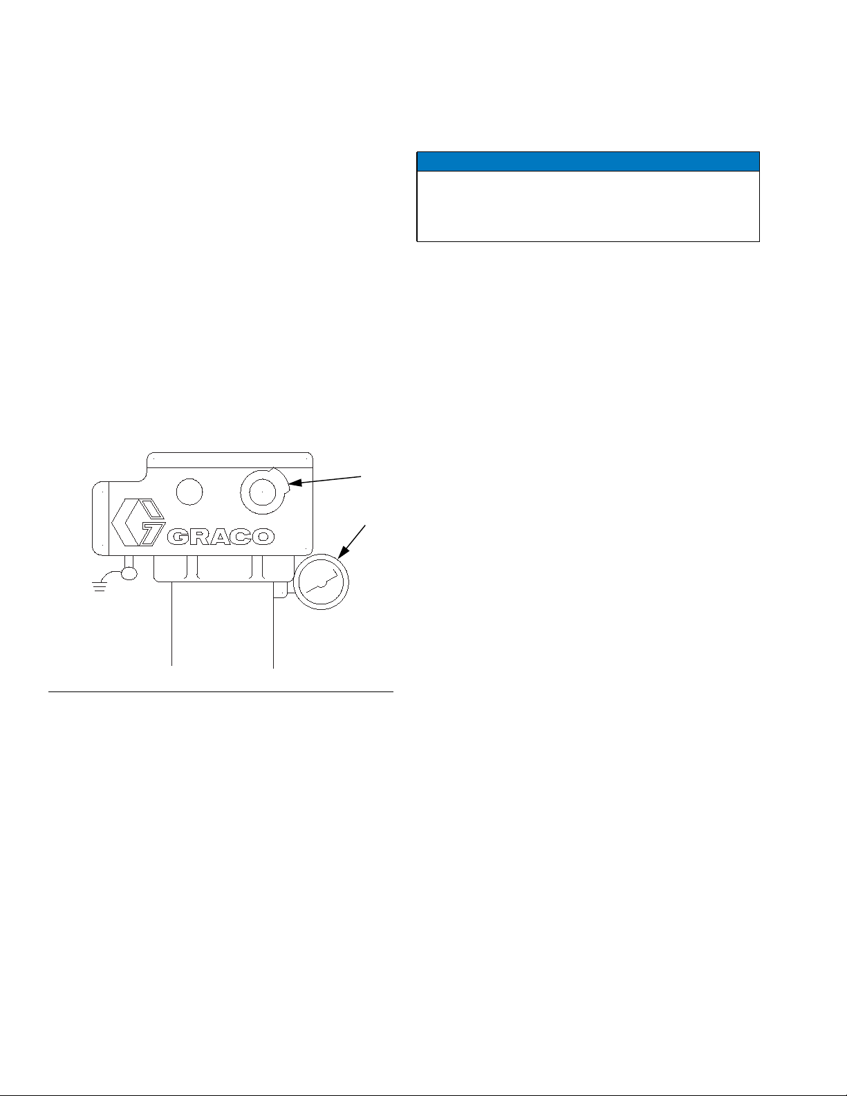
Setting Heater Control
(Refer to FIG.6)
This procedure applies to model 24P016 only. Heater
262853 with RTD control has no adjustments to make
on the heater, it requires use of an external temperature
controller.
1. Set the heater control knob (33) to a trial setpoint of
4or5.
2. Start the pump and circulate fluid through the system at a very low flow rate of about 10-12 oz/min
(0.30-0.35 liter/min).
3. After the indicator light turns off: read the temperature on the thermometer (2). If it does not match the
desired temperature, adjust the setpoint.
33
2
Adjusting for Spraying
NOTICE
Operating the heater at its highest setting of over
180°F (82°C) for long periods of time decreases the
heater life and can cause fluid to dry out which can
cause heater clogging and a poor spray pattern.
1. Adjust pump pressure and heater setpoint to the
lowest settings needed for good fluid atomization.
2. Set all system back pressure valves (S - FIG.1on
page 5) to maintain even fluid pressure at all gun
stations.
05549-524
FIG. 6: Setting Heater Control
12 3A2954D
Page 13
Maintenance
Maintenance
Flushing
To avoid fire and explosion, ensure main power is off
and heater is cool before flushing. Do not turn on
heater until fluid lines are clear of solvent.
Clogged fluid passages reduce heating efficiency, flow
rate, and pressure. Flush or clean whenever a change in
heating efficiency, flow rate, or pressure is noticed.
1. Follow Pressure Relief Procedure, page 11.
2. Ensure main power is off and heater is cool before
flushing. Use a compatible solvent, and follow flushing instructions in your fluid supply and spray gun
manual. Do not turn on heater until fluid lines are
clear of solvent.
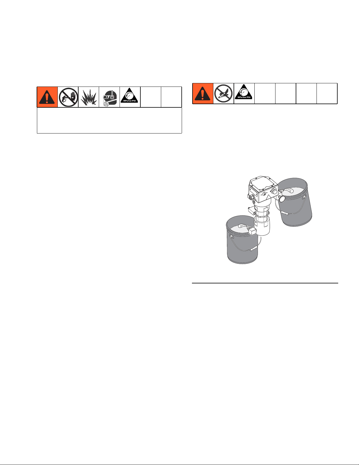
Drain the Heater
(FIG.7)
1. Follow Pressure Relief Procedure, page 11.
2. Remove heater inlet and outlet fittings or pipe plugs.
Have a container ready to catch the fluid.
Outlet
Inlet
FIG. 7: Drain the Heater
ti20057a
3A2954D 13
Page 14

Troubleshooting
Troubleshooting
Problem Cause Solution
Heater will not heat. No current. Check circuit and fuses.
Overtemperature switch (10) tripped. • Check continuity of
overtemperature switch. If
circuit is open, press red reset
switch and re-check.
Determine why switch opened
before restarting.
• Model 24P016 only: check that
the thermostat (24) is open
when the knob is turned to the
left and closed when turned to
the right.
Burned out heater cartridges (81). Replace cartridges.
Temperature too low. Fluid requires more warm-up time. Increase warm-up time.
Wrong temperature setting. Adjust setting, page 12.
Flow rate too high. Reduce flow rate or use 2 heaters.
Clogged fluid passages. Heater Core Removal and Fluid
Passage Unclogging, page 19.
One of the two heater cartridges (81)
failed.
Temperature too high. Wrong temperature setting. Adjust setting, page 12.
Failed primary thermostat (24). Replace, page 16.
High fluctuating temperatures, about
220-250°F (104-120°C) at 0.1 GPM.
Too much pressure drop or fluid will
not flow.
Heater fittings leak. Loose or damaged fittings. Tighten or replace fittings.
Heater temperature rises far beyond
the setpoint temperature during heating
Primary thermostat (24) contacts
sticking.
Flow rate too high. Reduce flow rate or use 2 heaters.
Clogged fluid passages. Flush or clean, page 13.
Model 262853 only: RTD sensor (88)
is installed too far into fluid path. Sensor does not sense aluminum core.
Heater core is dirty or has baked on
material.
Check each cartridge for a resistance
of approximately 21 ohms. The pair
in parallel should have a resistance
of approximately 10.7 ohms. See
Heater Cartridges on page 20.
Replace thermostat (24), page 16.
Replace sensor (88) and compression fitting (72). See page 21.
Disassemble and clean all parts that
come in contact with material.
14 3A2954D
Page 15
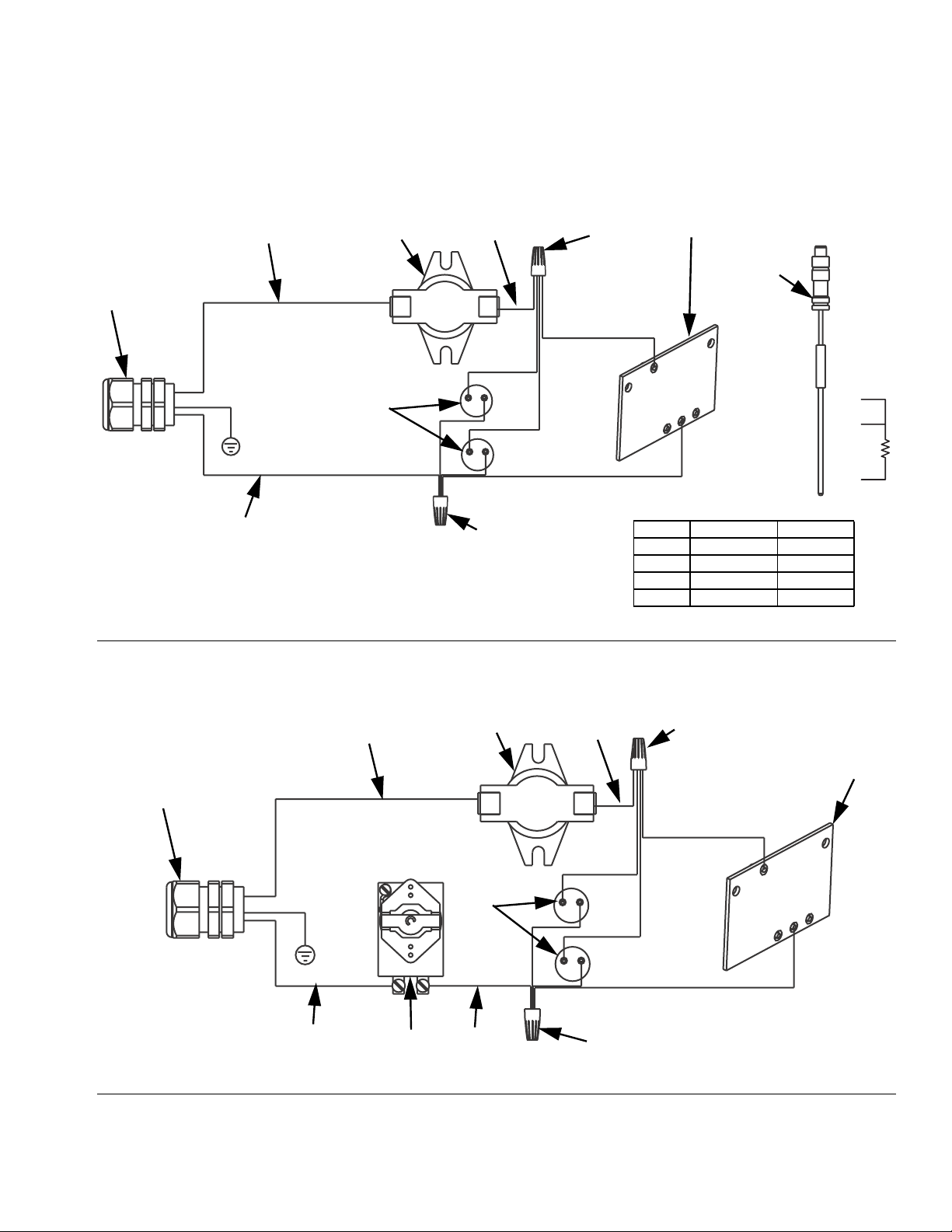
NOTE: See the Parts illustration that applies to your heater on page 22 or 24.
37
10
37
89
WHITE
87
260°F
53
Troubleshooting
RTD Sensor
(1000 ohm)
42, 88
81
BLACK
96
ti20062a
FIG. 8: Electrical Schematic - 262853 Heater with RTD
98
87
WHITE
89
10
260°F
98
4
1
3
RTD Pin Wire Color Signal
1 Red Excitation
2 --- ---
3 White RTD Element
4 Red Lead Ohms
89
53
81
BLACK
ti20063a
24
9737
89
FIG. 9: Electrical Schematic - 24P016 Heater with Thermostat
3A2954D 15
Page 16

Repair
Repair
To avoid burns, electric shock, and skin injection,
make sure the main power is OFF, heater is cool, and
pressure is relieved before repairing.
Overtemperature Switch
NOTE: This switch is a manual reset type. Press the red
button to reset the switch. Check for continuity across
the contacts. If the switch tripped, always determine the
cause before returning the heater to service.
1. Follow Pressure Relief Procedure, page 11.
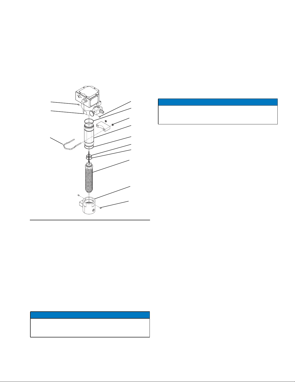
Primary Thermostat & Probe
(Model 24P016 Only, see FIG.10onpage17)
1. Perform Pressure Relief Procedure, page 11.
2. Remove screws (52) then remove housing
cover (18).
3. Loosen screws (25) that secure thermostat in place.
4. Remove wires from the primary thermostat terminals (FF).
5. Loosen setscrew (26) in switch shaft (28)
6. Pull thermostat probe (EE) out of heater block.
7. Remove thermostat (24) from housing (1).
8. Remove screw standoff (35) with washer (27).
9. Remove bracket from thermostat (24) and secure to
new thermostat.
NOTICE
To avoid damaging capillary tube (GG) of the thermostat, which can cause heater malfunction, do not kink
or nick the tube.
2. Remove screws (52) then remove housing
cover (18).
3. Unplug wires from tabs (HH) on switch.
4. Remove the two screws (16) securing the switch
then remove the switch (10).
5. Liberally apply thermal lubricant (part no. 110009) to
the bottom of the thermostat switch and reinstall it in
reverse order of disassembly.
Reassembly Notes
• Refer to FIG.8orFIG. 9 for wiring connections.
• Make sure gasket (47) is installed and aligned with
electrical housing screw holes.
• Secure cover (18) with screws (52). Torque screws
to 89 in-lb (10 N•m).
To avoid shorting out the heater, do not allow capillary
tube to contact the terminals on switch (10) or
thermostat (24). Follow step 10, below.
10. Liberally apply thermal lubricant (part no. 110009) to
probe (EE) of new thermostat (24). Loop capillary
tube (GG) several times and wrap the loops with tie
strap (42-not shown). Insert probe in the heater
block.
11. Continue reassembling in reverse order of disassembly. See the following Reassembly Notes section.
16 3A2954D
Page 17

Repair
10
16
52
18
47
25
EE
81
FIG. 10: Thermostat Repair - 24P016
54
24
GG
FF (not visible in current view)
27
35
26
28
29
25
51
50
48
20
33
JJ
HH
24
3030
12
52
18
47
10
16
88
72
25
54
HH
1
51
50
48
20
FIG. 11: Sensor Repair - 262853
3A2954D 17
Page 18

Repair
Control Knob
This procedure applies to heater 24P016 only. See the
Parts illustration on page 22.
1. Follow Pressure Relief Procedure, page 11.
2. Turn control knob (33) to setpoint 1.
3. Loosen the control knob setscrew (30).
4. Remove control knob.
5. Remove adjusting knob (12) from the control knob
and press fit it onto the new control knob. Check the
grommet (29) and replace if worn.
6. Position new knob so setpoint 1 aligns with the
12 o’clock position and the knob is about 1/16 in.
(1 mm) away from the housing. Install and tighten
setscrew (30).
18 3A2954D
Page 19
Repair
Heater Core Removal and Fluid Passage Unclogging
The heater core (68) can be removed for thorough
cleaning or replacement. See the Parts illustration that
applies to your heater on page 22 or 24.
83
67
78
83
76
90
66
76
79
70
68
65
9. Remove screws (52) then remove cover (18).
10. On model 262853 only, remove RTD sensor (88).
Loosen nut on compression fitting (72). Pull nut and
sensor straight up out of heater.
11. Remove 4 screws (71) from top of plate (69).
12. Disconnect heater cartridge (81) wire leads from
wire nuts (89).
NOTICE
To prevent damage to sensors and wiring, do not turn
core (68). The core pushes straight down out of
housing (67).
13. Pull heater core straight down out of the upper
housing (67).
14. Use a wire brush to clean outside fluid passages
until bare aluminum is visible.
NOTE: Model 24P016 Only: The capillary bulb/tube
from the thermostat (24) will slowly pull out of its hole in
the core (68). The heater core wires will pull down
through plate (69).
83
ti20065a
FIG.12
1. Follow Pressure Relief Procedure, page 11.
2. Disconnect power.
3. Drain the Heater, page 13.
4. Loosen set screws (83) from bottom inlet housing
witha3/16in.hexkey.
5. Unscrew bottom inlet housing (65).
6. Remove nuts (90) then remove cylinder u-bolt
clamp (78).
7. Loosen set screws (83) on upper fluid housing (67).
NOTICE
On model 262853 only, to prevent damaging the RTD
sensor (72), do not rotate the core (68) when performing the following step.
Reassembly Notes
• Always replace o-rings (70, 76, and 79).
• Refer to FIG.10orFIG. 11 on page 17 for wiring
connections.
• Model 262853 only: Make sure the core (68) is
aligned with the plug (82) pin in housing (67).
• Make sure gasket (47) is installed and aligned with
electrical housing screw holes.
• Secure cover (18) with screws (52). Torque screws
to 85-90 in-lb (10 N•m).
8. Unscrew cylinder (66). Pull down to remove.
3A2954D 19
Page 20

Repair
Heater Cartridges
See Parts illustration that applies to your heater on
page 22 or 24.
1. Follow Pressure Relief Procedure, page 11.
2. Disconnect power.
3. Drain the Heater, page 13.
4. Perform Heater Core Removal and Fluid Passage
Unclogging procedure on page 19. This includes
removing the inlet housing (65).
5. With the inlet housing removed, remove 5
screws (52) and cover (18).
6. Disconnect wires from heater cartridges (81).
7. Remove pipe plug (95) and springs (31) from bottom of core (68).
8. Use a 3/8 in. (10 mm) rod to push each cartridge out
of the top of the core.
9. Wire new cartridges per FIG.8orFIG. 9, page 15.
20 3A2954D
Page 21

Repair
RTD Sensor and Fitting Replacement
(Model 262853 Only)
1. Follow Pressure Relief Procedure, page 11.
2. Disconnect power.
3. Remove screws (52) then remove cover (18).
4. Disconnect M8 cable connection for sensor (88).
5. Loosen nut on compression fitting (72) and pull the
sensor (88) straight up and out.
6. Remove compression fitting.
Reassembly
NOTICE
Sensor (88) position cannot be changed once a compression fitting (72) has been tightened. A new sensor
(88) and a new compression fitting (72) must be used
if the position is wrong.
1/8 in. (1.6 to 3.2 mm) into fluid outlet, when looking
into the outlet. See FIG.13.
M8 Plug
1/16-1/8 in.
(1.6-3.2 mm)
ti20209a
FIG.13
NOTE: Sensor (88) and fitting (72) must be replaced
together.
1. Install new compression fitting (72) into
housing (67).
NOTICE
The RTD sensor must always be mounted on the outlet side of housing (67). If you plumb the outlet to the
left side, swap position of sensor (88) and plug (82).
2. Position sensor through housing (67) so it sticks
through the aluminum shoulder on core (68) 1/16 to
3. Tighten compression nut on fitting (72) 3/4 turn after
it holds sensor tight.
4. Connect M8 plug.
5. Install cover.
3A2954D 21
Page 22

Parts
Parts
24P016
48
20
12
7
13
12
14
4
36
87
5150
33
53
25
92
5
64
4
54
30
43
14
57
15
8
52
18
47
9
1
5
24
5
14
17
91
27
35
25
28,
26
4
29
16
10
75
2
74
5
83
84
67
14
3
83
90
5
77
78
16
9
11
66
17
76
1
79
70
81
68
6
69
82
2
2
Apply sealant (39) and tape (44).
3
Torque to 7-11 ft-lb (10-15 N•m).
4
Loosen setscrew (26). Turn shaft (28)
clockwise and re-tighten setscrew (26).
Turn shaft counter-clockwise. Install
knob (33) with “1” at 12 o’clock
position. Tighten knob setscrew (30).
5
Apply sealant (34).
6
Apply thermal lubricant (38) to bottom
of flange (10).
7
Press fit onto knob (33).
71
5
83
5
7
14
2
67
16
75
2
32
93
2
49
2
2
9
9
Apply thermal lubricant (38) completely
covering probe before inserting.
11
Wrap capillary tube of thermostat (24)
and attach strap (42).
nick tube. Position wrapped
capillary tube between
thermostat (24) and wall of
enclosure (1) maintaining at least
0.6 in. from heating element.
12
Connect appropriate wire (240V) and
terminal end (part of item 53) to heater
terminal.
13
Apply adhesive (56) if required.
13
Do not kink or
96
73
73
2
31
95
2
65
17
83
2
ti20061a
14
Apply spray adhesive as necessary on
gasket.
15
Locate on wall of housing near (8).
16
Assemble sleeve (66) to housing (67).
After bottoming parts together loosen
between 0 and 90 degrees to align set
screws (83) to sleeve flats (66).
17
Assemble housing (65) to sleeve (66).
After bottoming parts together loosen
between 0 and 180 degrees to align set
screws (83) to sleeve flats (66).
18
Cut wires from board.
75
2
22 3A2954D
Page 23

24P016
Ref Part Description Qty
1 --- ENCLOSURE, controls, heater 1
2 102124 THERMOMETER, dial 1
5 107542 WASHER, lock, spring 6
7 15A990 GASKET, heater 1
8 116343 SCREW, ground 1
9 117367 SCREW, socket head cap,
M8 x 18
10 24P291 THERMOSTAT SWITCH 1
12 177969 KNOB, adjusting 1
13▲ 177922 TAG, warning 1
14 100055 SCREW, drive, #6 10
16 105676 SCREW, machine, pan head 2
17 --- LABEL, brand 1
18 15A810 COVER, heater controls, top 1
20 15B828 HOUSING, light, heater 1
24 108676 THERMOSTAT 1
25 100032 SCREW, machine, pan head 4
26 105672 SCREW, set, socket cap head 1
27 114027 WASHER, flat 2
28 183068 SHAFT, switch 1
29 112738 GROMMET 1
30 101366 SCREW, set, socket cap head 1
31† 16A240 SPRING, compression 2
32 16R930 FITTING, tee, thermometer, 3/4 1
33 177968 KNOB, control 1
34 --- SEALANT, anaerobic 1
35 117526 SPACER, standoff, threaded 2
36▲ 15B623 LABEL, electric shock warning 1
37 246346 WIRE, assy 1
38† 110009 LUBRICANT, thermal, 1 oz tube 1
39† --- SEALANT, pipe, stainless steel 1
42 --- STRAP, tie wiring 1
43▲ 15B625 LABEL, multiple warnings, English 1
44 --- TAPE, tfe, sealant 1
47 15A991 GASKET, heater 1
48 15B827 LENS, light, glass 1
49 15D757 HOUSING, thermometer 1
50 103338 PACKING, o-ring 1
51 117483 SCREW, jam, socket 1
52 111962 SCREW, cap, button head 5
53 246014 BOARD, circuit, heater indicator
light assembly
54 106216 NUT, lock 1
56 --- SEALANT, anaerobic 1
57▲ 172953 LABEL, grounding symbol, round 1
60▲◆ 15B819 LABEL, multiple warnings,
multi-language
64 111307 WASHER, lock, external 1
Ref Part Description Qty
65 24P019 HOUSING, inlet, heater 1
66 24P021 SLEEVE, center, heater 1
67 24P020 HOUSING, outlet, heater 1
68† --- CORE, spiral, heater 1
69 16P607 PLATE, mounting, heater 1
70† 164891 PACKING, o-ring 1
71† 103374 SCREW, machine, round head 4
6
73 16R883 FITTING, nipple, reducing, 3/4 x
1/2
74 --- SCREW, machine, serrated hex
head; 5/16-18 x 2.5 in.
75 102726 PLUG, pipe headless, 3/4 in. 4
76† 126396 PACKING, o-ring, PTFE, 235 2
77 16P609 CLAMP, mounting, bottom, heater 1
78 16P610 CLAMP, u-bolt, heater 1
79† 102930 PACKING, o-ring 1
81 16P821 CARTRIDGE, heater, 2700W,
240V
82 556410 PLUG, steel 1/8 pipe hex head 2
83 101679 SCREW, set, socket cap 4
84 16P608 CLAMP, mounting, top, heater 1
87 121603 GRIP, cord, 0.51-0.71, 3/4 1
89◆ 122032 NUT, wire 3
90 110996 NUT, hex, flange head 2
91▲ 189285 LABEL, burn hazard, triangular 1
92▲ 189930 LABEL, shock hazard, triangular 1
93 16R882 FITTING, nipple, 3/4 1
95† 105325 PLUG, pipe 1
96 166590 FITTING, elbow, street, high
pressure
97 16T515 WIRE, assembly, ring x quick
connect
98 16T502 WIRE, assembly 1
--- Not for sale.
▲ Replacement Danger and Warning labels, tags and
cards are available at no cost.
◆ Not shown.
† Parts included in Heater Core (68) Replacement Kit
1
1
24P022.
Parts
2
2
2
1
1
3A2954D 23
Page 24

Parts
262853
36
86,85
87
48
20
14
50
25
25
51
64
54
43
75
2
74
14
84
52
8
18
47
14
3
9
78
5
1
67
83
90
77
66
76
21
21
79
70
14
81
17
68
91
7
10
69
67
73
14
6
21
31
95
83
2
21
16
2
82
1
71
24
6
82
88
20
2
72
83
21
2
93
2
94
1
Apply medium strength, thread-locking fluid.
2
Apply sealant (39) and tape (44).
3
Torque to 7-11 ft-lb (10-15 N•m).
6
Apply thermal lubricant (38) to bottom of flange (10) and
plate (82) and top of core (68).
12
Connect appropriate wire (240V) and terminal end (part of item
53) to heater terminal.
14
Apply spray adhesive as necessary on gasket.
32
2
75
13
18
Cut wires from board. Cut ring terminals from white wire and
240V black wire. Strip wire for connection to wire nuts (89).
19
Power cord is user supplied.
20
Secure RTD connector (88) with tie strap (42) to RTD stem (88).
21
Assemble sleeve (66) to housing (67). After bottoming parts
together loosen between 0 and 90 degrees to align set
screws (83) to sleeve flats (66).
24
Tighten screws adequately to compress o-ring (70). Plate (69)
and core (68) must be tight against each other.
75
73
65
2
2
21
ti20060a
24 3A2954D
Page 25

Parts
262853
Ref Part Description Qty
1 --- ENCLOSURE, controls, heater 1
5 107542 WASHER, lock, spring 6
7 15A990 GASKET, heater 1
8 116343 SCREW, ground 1
9 117367 SCREW, shcs, m8x18 6
10 24P291 THERMOSTAT SWITCH 1
13▲ 177922 TAG, warning 1
14 100055 SCREW, drive, #6 10
16 105676 SCREW, machine, pan head 2
17 --- LABEL, brand 1
18 15A810 COVER, heater controls, top 1
20 15B828 HOUSING, light, heater, viscon
hp
25 100032 SCREW, machine, pan head 2
31† 16A240 SPRING, compression 2
32 16R930 FITTING, tee, thermometer, 3/4 1
36▲ 15B623 LABEL, electric shock warning 1
37 16T502 WIRE, assembly 2
38† 110009 LUBRICANT, thermal, 1 oz tube 1
39† --- SEALANT, pipe, stainless steel 1
42 --- STRAP, tie wiring 2
43▲ 15B625 LABEL, multiple warnings,
English
44 --- TAPE, tfe, sealant 1
47 15A991 GASKET, heater 1
48 15B827 LENS, light, glass 1
50 103338 PACKING, o-ring 1
51 117483 SCREW, jam, socket 1
52 111962 SCREW, cap, button head 5
53 246014 BOARD, circuit, heater indicator
light assembly
54 106216 NUT, lock 1
57▲ 172953 LABEL, grounding symbol, round 1
60▲◆ 15B819 LABEL, multiple warnings,
multi-language
64 111307 WASHER, lock, external 1
65 24P019 HOUSING, inlet, heater 1
66 24P021 SLEEVE, center, heater 1
67 24P020 HOUSING, outlet, heater 1
68† --- CORE, spiral, heater 1
69 16P607 PLATE, mounting, heater 1
70† 164891 PACKING, o-ring, PTFE, #135 1
71† 103374 SCREW, machine, round head 4
72 126351 FITTING, compression,
thermocouple
73 16R883 FITTING, nipple, reducing, 3/4 x
1/2
74 126669 SCREW, machine, serrated hex
head; 5/16-18 x 2.5 in.
75 102726 PLUG, pipe headless, 3/4 in. 4
Ref Part Description Qty
76† 126396 PACKING, o-ring, PTFE, 235 2
77 16P609 CLAMP, mounting, bottom,
heater
78 16P610 CLAMP, u-bolt, heater 1
79† 102930 PACKING, o-ring 1
81 16P821 CARTRIDGE, heater, 2700W,
240V
82 16V591 PLUG, steel locator 1
83 101679 SCREW, set, socket cap 4
84 16P608 CLAMP, mounting, top, heater 1
85 260067 FITTING, strain relief, 1/2 npt 1
86 117625 NUT, locking 1
87 121603 GRIP, cord, 0.51-0.71, 3/4 1
1
88 126381 SENSOR, RTD, 1k ohm, 4 pin 1
89◆ 122032 NUT, wire 3
90 110996 NUT, hex, flange head 2
91▲ 189285 LABEL, burn hazard, triangular 1
92▲ 189930 LABEL, shock hazard, triangular 1
93 16R882 FITTING, nipple, 3/4 1
94 198292 PLUG, pipe, 3/8 npt 1
95† 105325 PLUG, pipe 1
1
--- Not for sale.
▲ Replacement Danger and Warning labels, tags and
cards are available at no cost.
◆ Not shown.
† Parts included in Heater Core (68) Replacement Kit
24P022.
1
1
1
2
2
1
2
3A2954D 25
Page 26
Accessories
Accessories
Mounting Bracket
192585
AB
D
C
E
Dimensions – inches (mm)
A B C (4x) D E F (2x)
5.0
(127)
6.76
(172)
0.88
(22.4)
3.37
(85.6)
F
6.25
(158.8)
M8
7761a
1.44
(36.6)
Cart Bracket
For mounting heaters to 2.5 in. (63 mm) square tube
frames. Order 2 each of the following.
183484: Clamp
183485: Mounting bar
74
90
183484
183485
ti20055a
74 & 90 screw and nut included with heater
Thermal Lubricant
110009: 1 fluid ounce tube
26 3A2954D
Page 27

Technical Data
Technical Data
The heater can be used in the following environmental conditions: indoor use, 99% maximum relative humidity, pollution degree 2, installation category II, maximum ambient temperature 135° F (57° C).
Maximum Working Pressure ...................... 7250 psi (50 MPa, 500 bar)
Voltage/Wattage/Current*...................... SeeModels on page 2.
Fluid Passage Heat Transfer Area .................
Fluid Passage Dimensions (3 parallel paths) ......... Height: 0.41 in.
Fluid Passage Equivalent Diameter................. 0.72in.(18.3mm)
Thermometer Range ............................ 64-250°F (18 - 121°C)
WettedParts .................................. StainlessSteel,Anodized Aluminum, Electroless
Temperature Operating Range .................... 84-219°F (29 - 104°C)
Weight....................................... 51lb(23.2kg)
RTD (Model 262853 only) ........................ 1000 ohm, class B, 3-wire
* Main supply fluctuation not to exceed 10%.
210 in.2(1355 cm2)
Width: 0.32 in.
Length: 3x48in.
Nickel-Plated Steel, PTFE
Connector: M8, 4-pin male
3A2954D 27
Page 28

Technical Data
Performance Charts
Outlet Temperature versus Flow Rate (at each knob setting)
170
166
9
160
150
143
140
8
Viscon HF Heater with 70°F Test Oil
138
105
88.1
121
112
128
96
108
101
86.4
122
115
93
120
112
105
99
92
86
130
120
110
100
Maximum Temperature Rise (°F)
90
80
0.00 0.25 0.50 0.75 1.0 0 1.25 1.50 1.7 5
128
7
6
115
103
5
128
118
109
99
4
91
89.5
Flow Rate (gpm)
Temperature Rise versus Flow Rate (at each knob setting)
100
93
90
80
70
60
50
40
30
20
Maximum Temperature Rise (°F)
10
0
0.00 0.2 5 0.50 0.75 1.0 0 1.25 1.50 1.75
9
64
8
50.9
7
37.1
6
24.6
5
14.2
4
Viscon HF Heater with 72°F Test Oil
70.1
60
53.3
45.8
40.5
27.6
19.9
10.7
33.4
22.9
16.2
7.7
Flow Rate (gpm)
5.6
41.1
30.1
19.7
13.6
53.2
49.9
38.7
28.1
18.1
17.1
11.7
3.7
119
111
104
98
92
86
49
37.8
27.2
10.8
3
28 3A2954D
Page 29
Technical Data
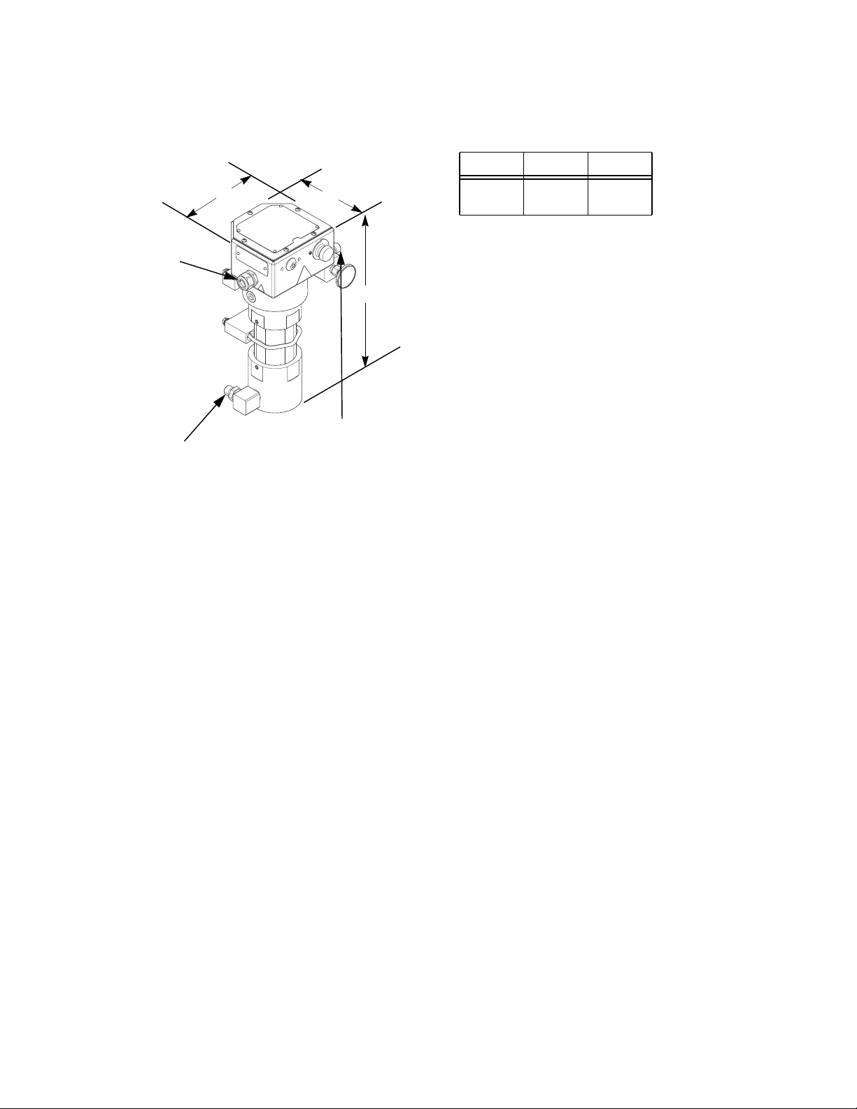
Dimensions
Stain Relief
in 3/4 npt(f)
Electrical
Conduit Port
1/2 in. npt(m)
Fluid Inlet shown
Model 24P016 shown
A
ti20064a
B
C
3/4-14 npt(f)
Fluid Outlet
with a 3/4 x
1/2 nipple
Measurements – inches (mm)
ABC
7.25
(184)
7.0
(178)
17.75
(451)
NOTE:
• 24P016 comes with a 3/4 in. street elbow and a 3/4
x 1/2 inlet nipple.
• 262853 comes with a 3/4 x 1/2 inlet nipple pointing
to the back.
• Lower inlet housing can be turned to face the front,
back, left, or right.
3A2954D 29
Page 30

Graco Standard Warranty
Graco warrants all equipment referenced in this document which is manufactured by Graco and bearing its name to be free from defects in
material and workmanship on the date of sale to the original purchaser for use. With the exception of any special, extended, or limited warranty
published by Graco, Graco will, for a period of twelve months from the date of sale, repair or replace any part of the equipment determined by
Graco to be defective. This warranty applies only when the equipment is installed, operated and maintained in accordance with Graco’s written
recommendations.
This warranty does not cover, and Graco shall not be liable for general wear and tear, or any malfunction, damage or wear caused by faulty
installation, misapplication, abrasion, corrosion, inadequate or improper maintenance, negligence, accident, tampering, or substitution of
non-Graco component parts. Nor shall Graco be liable for malfunction, damage or wear caused by the incompatibility of Graco equipment with
structures, accessories, equipment or materials not supplied by Graco, or the improper design, manufacture, installation, operation or
maintenance of structures, accessories, equipment or materials not supplied by Graco.
This warranty is conditioned upon the prepaid return of the equipment claimed to be defective to an authorized Graco distributor for verification of
the claimed defect. If the claimed defect is verified, Graco will repair or replace free of charge any defective parts. The equipment will be returned
to the original purchaser transportation prepaid. If inspection of the equipment does not disclose any defect in material or workmanship, repairs will
be made at a reasonable charge, which charges may include the costs of parts, labor, and transportation.
THIS WARRANTY IS EXCLUSIVE, AND IS IN LIEU OF ANY OTHER WARRANTIES, EXPRESS OR IMPLIED, INCLUDING BUT NOT LIMITED
TO WARRANTY OF MERCHANTABILITY OR WARRANTY OF FITNESS FOR A PARTICULAR PURPOSE.
Graco’s sole obligation and buyer’s sole remedy for any breach of warranty shall be as set forth above. The buyer agrees that no other remedy
(including, but not limited to, incidental or consequential damages for lost profits, lost sales, injury to person or property, or any other incidental or
consequential loss) shall be available. Any action for breach of warranty must be brought within two (2) years of the date of sale.
GRACO MAKES NO WARRANTY, AND DISCLAIMS ALL IMPLIED WARRANTIES OF MERCHANTABILITY AND FITNESS FOR A
PARTICULAR PURPOSE, IN CONNECTION WITH ACCESSORIES, EQUIPMENT, MATERIALS OR COMPONENTS SOLD BUT NOT
MANUFACTURED BY GRACO. These items sold, but not manufactured by Graco (such as electric motors, switches, hose, etc.), are subject to
the warranty, if any, of their manufacturer. Graco will provide purchaser with reasonable assistance in making any claim for breach of these
warranties.
In no event will Graco be liable for indirect, incidental, special or consequential damages resulting from Graco supplying equipment hereunder, or
the furnishing, performance, or use of any products or other goods sold hereto, whether due to a breach of contract, breach of warranty, the
negligence of Graco, or otherwise.
FOR GRACO CANADA CUSTOMERS
The Parties acknowledge that they have required that the present document, as well as all documents, notices and legal proceedings entered into,
given or instituted pursuant hereto or relating directly or indirectly hereto, be drawn up in English. Les parties reconnaissent avoir convenu que la
rédaction du présente document sera en Anglais, ainsi que tous documents, avis et procédures judiciaires exécutés, donnés ou intentés, à la suite
de ou en rapport, directement ou indirectement, avec les procédures concernées.
Graco Information
For the latest information about Graco products, visit www.graco.com.
TO PLACE AN ORDER, contact your Graco distributor or call to identify the nearest distributor.
Phone: 612-623-6921 or Toll Free: 1-800-328-0211 Fax: 612-378-3505
All written and visual data contained in this document reflects the latest product information available at the time of publication.
GRACO INC. AND SUBSIDIARIES • P.O. BOX 1441 • MINNEAPOLIS MN 55440-1441 • USA
Copyright 2012, Graco Inc. All Graco manufacturing locations are registered to ISO 9001.
Graco reserves the right to make changes at any time without notice.
)RUSDWHQWLQIRUPDWLRQVHHZZZJUDFRFRPSDWHQWV
2ULJLQDOLQVWUXFWLRQV This manual contains English. MM 3A2954
Graco Headquarters: Minneapolis
International Offices: Belgium, China, Japan, Korea
www.graco.com
Revised May 2013
 Loading...