

Page 1
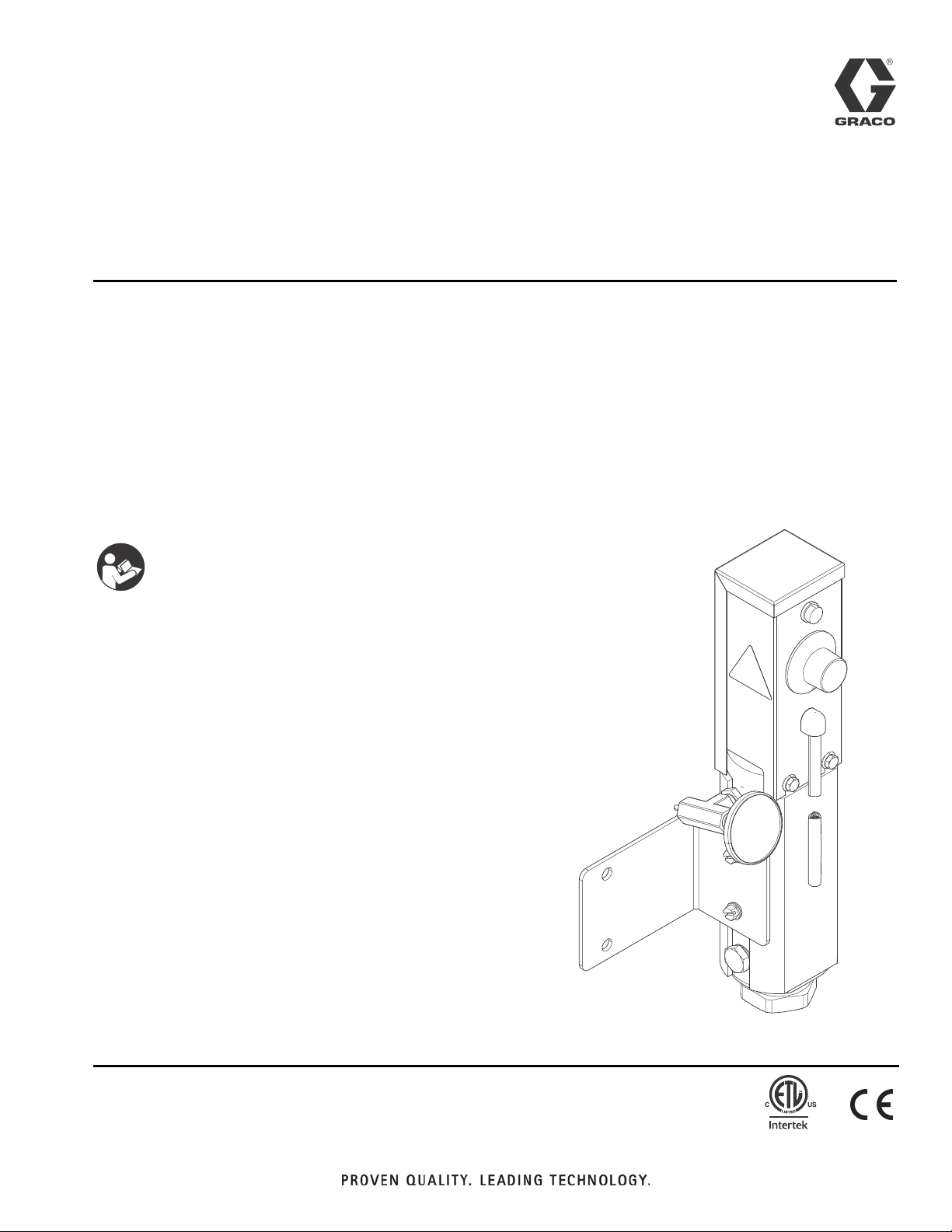
Instructions - Parts
®
Viscon
LT
3A2824B
Fluid Heater
For variable heating of fluids.
Not approved for use in explosive atmospheres or hazardous locations.
Model No. 16T525
1750 W; 7.3 A; 240VAC; 50/60Hz, 1 Phase
2000 psi (14 MPa, 138 bar) Maximum Working Pressure
Important Safety Instructions
Read all warnings and instructions in this manual.
Save these instructions.
EN
TI19998a
9902471
Conforms to
UL Std. 499
CSA Std. 22.2 No. 88
Page 2

Contents
Warnings .................................3
Installation ................................ 5
TypicalInstallationDrawing ................ 5
Component Identification ....................6
General Information ......................7
SelectingTubing .........................7
Mounting Heater .........................8
Fluid Connections and Accessories ..........9
Electrical Connections ................... 10
Operation ................................11
Pressure Relief Procedure ................11
Initial Flushing .........................11
Priming System .........................11
Setting Heater Control ................... 12
Troubleshooting .........................13
Repair ................................... 13
Before Beginning Repair ..................13
Heater Temperature Controls .............. 14
Parts ....................................18
Accessories .............................. 19
TechnicalData ............................ 20
Schematic Diagram ...................... 20
Dimensions ............................ 21
Graco Standard Warranty ................... 22
GracoInformation ........................ 22
2 3A2824B
Page 3
Warnings
Warnings
The following warnings are for the setup, use, grounding, maintenance, and repair of this equipment. The exclamation point symbol alerts you to a general warning and the hazard symbols refer to procedure-specific risks. When
these symbols appear in the body of this manual or on warning labels, refer back to these Warnings. Product-specific
hazard symbols and warnings not covered in this section may appear throughout the body of this manual where
applicable.
WARNING
ELECTRIC SHOCK HAZARD
This equipment must be grounded. Improper grounding, setup, or usage of the system can cause electric shock.
• Turn off and disconnect power cord before servicing equipment.
• Connect only to grounded electrical outlets.
• Use only 3-wire extension cords.
• Ensure ground prongs are intact on power and extension cords.
• Do not expose to rain. Store indoors
BURN HAZARD
Equipment surfaces and fluid that’s heated can become very hot during operation. To avoid severe
burns:
• Do not touch hot fluid or equipment.
SKIN INJECTION HAZARD
High-pressure fluid from gun, hose leaks, or ruptured components will pierce skin. This may look like just
a cut, but it is a serious injury that can result in amputation. Get immediate surgical treatment.
• Do not spray without tip guard and trigger guard installed.
• Engage trigger lock when not spraying.
• Do not point gun at anyone or at any part of the body.
• Do not put your hand over the spray tip.
• Do not stop or deflect leaks with your hand, body, glove, or rag.
• Follow the Pressure Relief Procedure when you stop spraying and before cleaning, checking, or
servicing equipment.
• Tighten all fluid connections before operating the equipment.
• Check hoses and couplings daily. Replace worn or damaged parts immediately.
FIRE AND EXPLOSION HAZARD
Flammable fumes, such as solvent and paint fumes, in work area can ignite or explode. To help prevent
fire and explosion:
• Use equipment only in well ventilated area.
• Eliminate all ignition sources; such as pilot lights, cigarettes, portable electric lamps, and plastic drop
cloths (potential static arc).
• Keep work area free of debris, including solvent, rags and gasoline.
• Do not plug or unplug power cords, or turn power or light switches on or off when flammable fumes
are present.
• Ground all equipment in the work area. See Grounding instructions.
• Use only grounded hoses.
• Hold gun firmly to side of grounded pail when triggering into pail. Do not use pail liners unless they
are antistatic or conductive.
• Stop operation immediately if static sparking occurs or you feel a shock. Do not use equipment
until you identify and correct the problem.
• Keep a working fire extinguisher in the work area.
3A2824B 3
Page 4
Warnings
WARNING
TOXIC FLUID OR FUMES HAZARD
Toxic fluids or fumes can cause serious injury or death if splashed in the eyes or on skin, inhaled, or
swallowed.
• Read MSDSs to know the specific hazards of the fluids you are using.
• Store hazardous fluid in approved containers, and dispose of it according to applicable guidelines.
PERSONAL PROTECTIVE EQUIPMENT
Wear appropriate protective equipment when in the work area to help prevent serious injury, including
eye injury, hearing loss, inhalation of toxic fumes, and burns. This protective equipment includes but is
not limited to:
• Protective eyewear, and hearing protection.
• Respirators, protective clothing, and gloves as recommended by the fluid and solvent manufacturer
EQUIPMENT MISUSE HAZARD
Misuse can cause death or serious injury.
• Do not operate the unit when fatigued or under the influence of drugs or alcohol.
• Do not exceed the maximum working pressure or temperature rating of the lowest rated system
component. See Technical Data in all equipment manuals.
• Use fluids and solvents that are compatible with equipment wetted parts. See Technical Data in all
equipment manuals. Read fluid and solvent manufacturer’s warnings. For complete information
about your material, request MSDS from distributor or retailer.
• Do not leave the work area while equipment is energized or under pressure.
• Turn off all equipment and follow the Pressure Relief Procedure when equipment is not in use.
• Check equipment daily. Repair or replace worn or damaged parts immediately with genuine manufacturer’s replacement parts only.
• Do not alter or modify equipment. Alterations or modifications may void agency approvals and create
safety hazards.
• Make sure all equipment is rated and approved for the environment in which you are using it.
• Use equipment only for its intended purpose. Call your distributor for information.
• Route hoses and cables away from traffic areas, sharp edges, moving parts, and hot surfaces.
• Do not kink or over bend hoses or use hoses to pull equipment.
• Keep children and animals away from work area.
• Comply with all applicable safety regulations.
PRESSURIZED ALUMINUM PARTS HAZARD
Use of fluids that are incompatible with aluminum in pressurized equipment can cause serious chemical
reaction and equipment rupture. Failure to follow this warning can result in death, serious injury, or property damage.
• Do not use 1,1,1-trichloroethane, methylene chloride, other halogenated hydrocarbon solvents or
fluids containing such solvents.
• Many other fluids may contain chemicals that can react with aluminum. Contact your material supplier for compatibility.
THERMAL EXPANSION HAZARD
Fluids subjected to heat in confined spaces, including hoses, can create a rapid rise in pressure due to
the thermal expansion. Over-pressurization can result in equipment rupture and serious injury.
• Open a valve to relieve the fluid expansion during heating.
• Replace hoses proactively at regular intervals based on your operating conditions.
4 3A2824B
Page 5
Installation
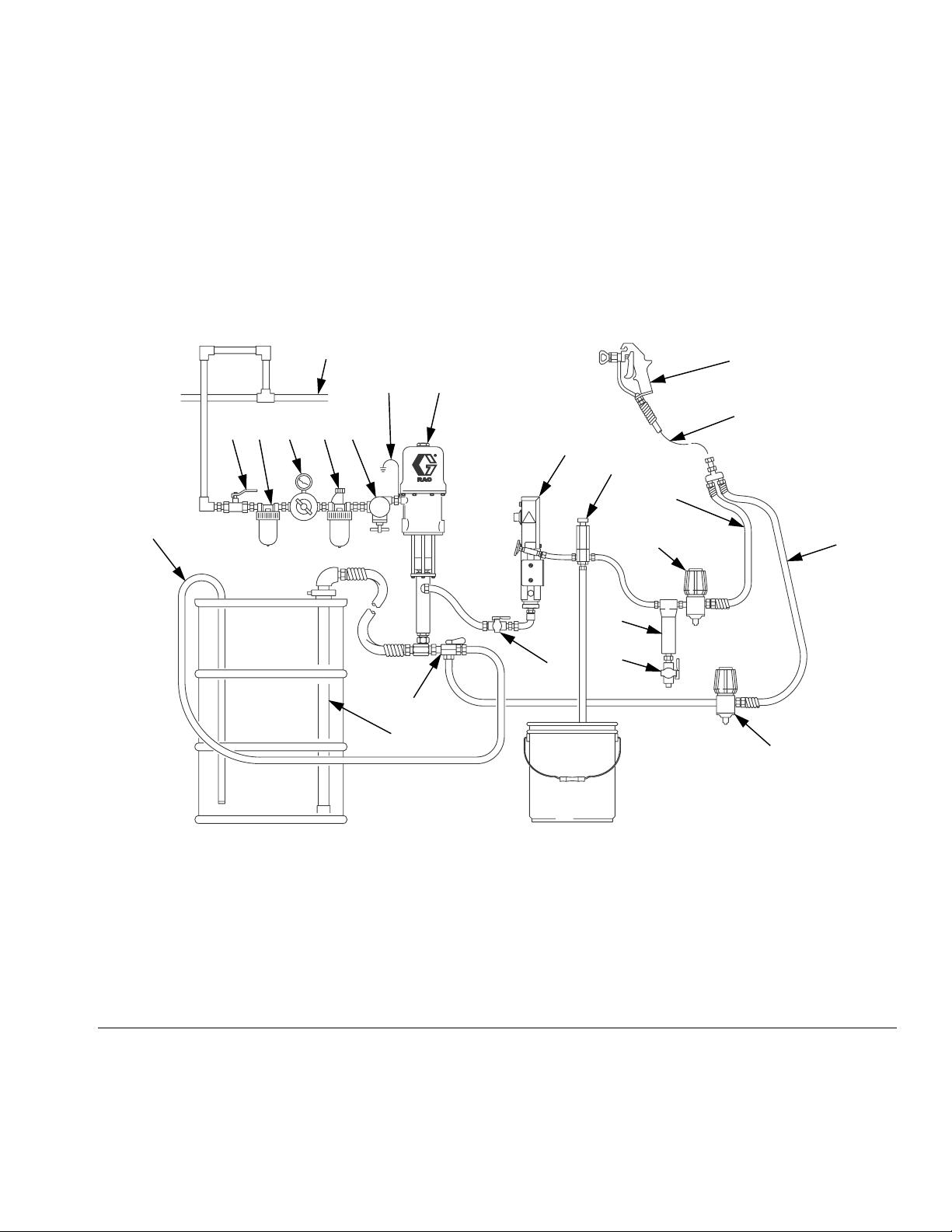
Typical Installation Drawing
The typical installation drawing is only a guide. Your Graco distributor can assist in designing your system.
Installation
Z
Q
GF
Y
EDCBA
K
X
P
V
N
R
L
M
T
U
W
S
ti19999a
Key:
A Bleed-type Master Air Valve
B Air Filter
C Air Regulator and Gauge
D Air Line Lubricator
E Pump Runaway Valve
F Ground Wire
G Pump
K Heater
L Fluid Filter
M Drain Valve
N Fluid Pressure Regulator
P Fluid Supply Line
Q Spray Gun
R Fluid Return Line
S Back Pressure Valve
T Fluid Shutoff Valve
U Director Valve
V Drain Back Tube
W Suction Tube
X Pressure Relief Valve
Y Whip End Hose
Z Air Supply Line
FIG. 1: Typical Installation – Heated Circulating System
3A2824B 5
Page 6
Component Identification
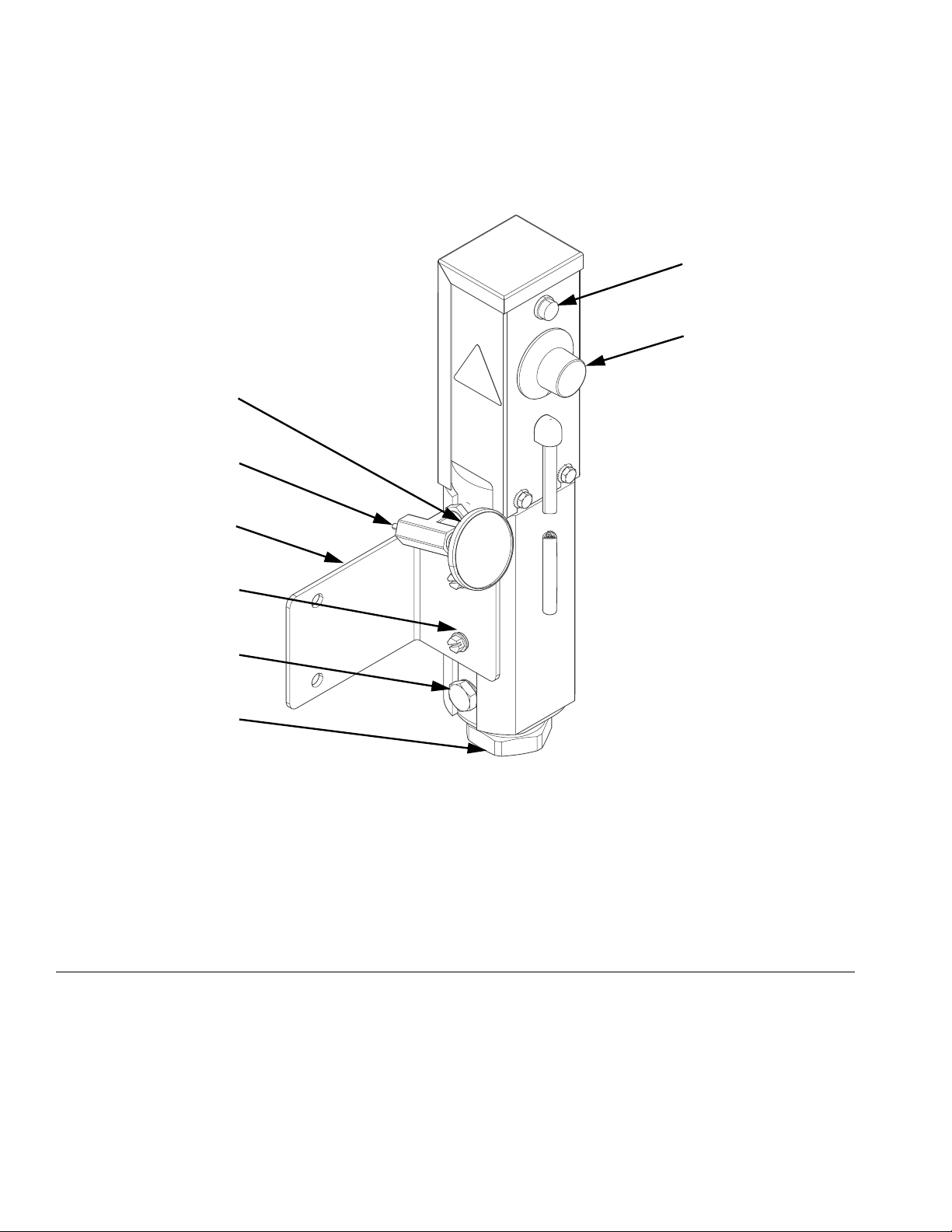
Component Identification
AE
AD
AB
AA
AF
AH
AG
AC
Key:
AA Temperature control
AB Heater light (illuminated while
heating)
AC Heater inlet, 3/8 npt(f)
AD Heater outlet, 1/4 npt(f)
FIG. 2: Typical Installation – Heated Circulating System
ti19998a
AE Outlet thermometer
AF Mounting bracket
AG Heater plug
AH Insulating washers
6 3A2824B
Page 7
Component Identification
General Information
• Select system components that meet temperature
and pressure ratings listed in Technical Data,
page 20. The heater’s normal output range is
adjustable from 84-180°F (29-82°C).
• To prevent fire and explosion, locate heater away
from all flammable materials and where operators
will not come in contact with hot metal surfaces.
• To avoid burns, insulate and/or label lines and
components exiting heater that may become hot.
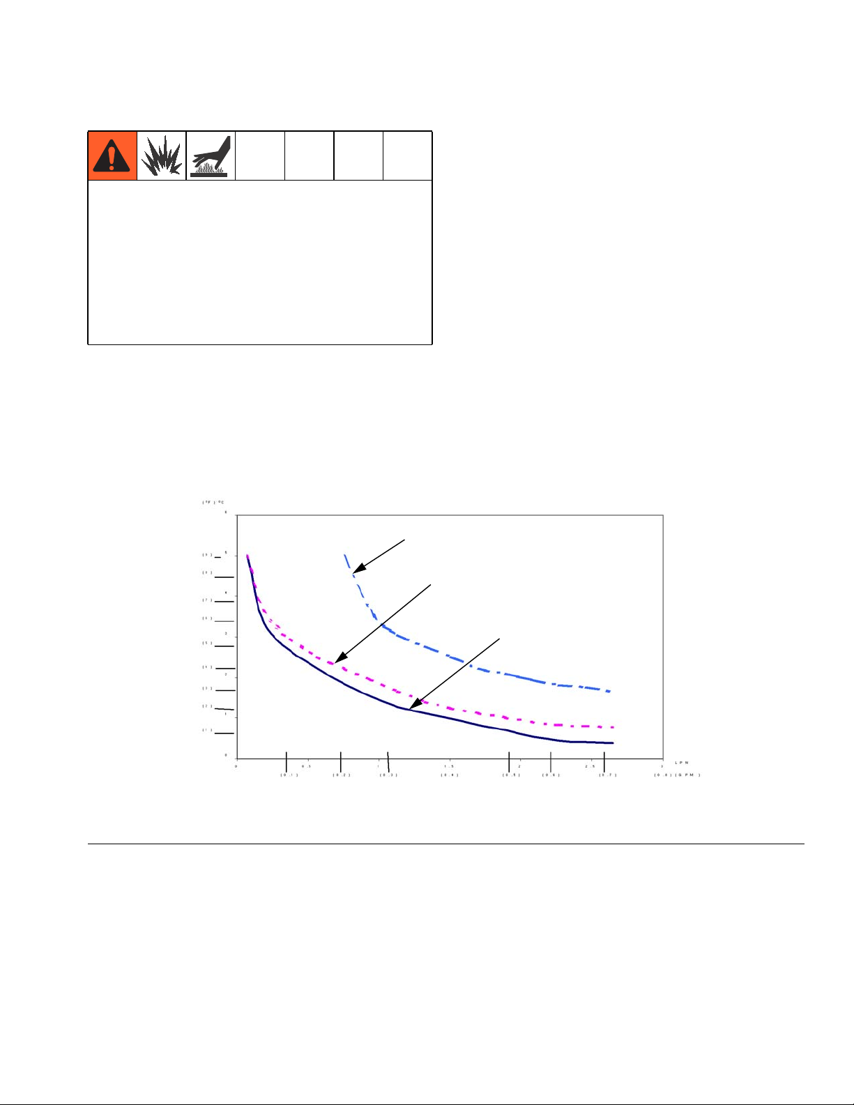
Heat Loss Curve: 70°F (21°C) Ambient
Selecting Tubing
Fluid loses some heat through the tubing or hose
between the heater and spray gun. Locate heater close
to the spray area to minimize heat loss through plumbing.
The chart in F
mon types of tubing.
Chart Notes:
• Higher flow rates have less heat loss.
• Foam-insulated steel tubing and high pressure airless paint hose retain heat best. Insulated tubing
and hose are more expensive, but higher costs are
commonly offset by lower operating costs.
IG. 3 shows a heat loss curve for 3 com-
Typical Fluid Temperature Drop
FIG. 3: Typical Temperature Drop
(20 ft.) 6.1 m steel tube
Fluid: (130° F) 54° C
(20 ft.) 6.1 m steel tube
(3/8 in.) 9 mm foam insulation
Fluid: (110° F) 43° C
(20 ft.) 6.1 m airless paint hose
Fluid: (110° F) 43° C
Flow Rate
3A2824B 7
Page 8
Component Identification
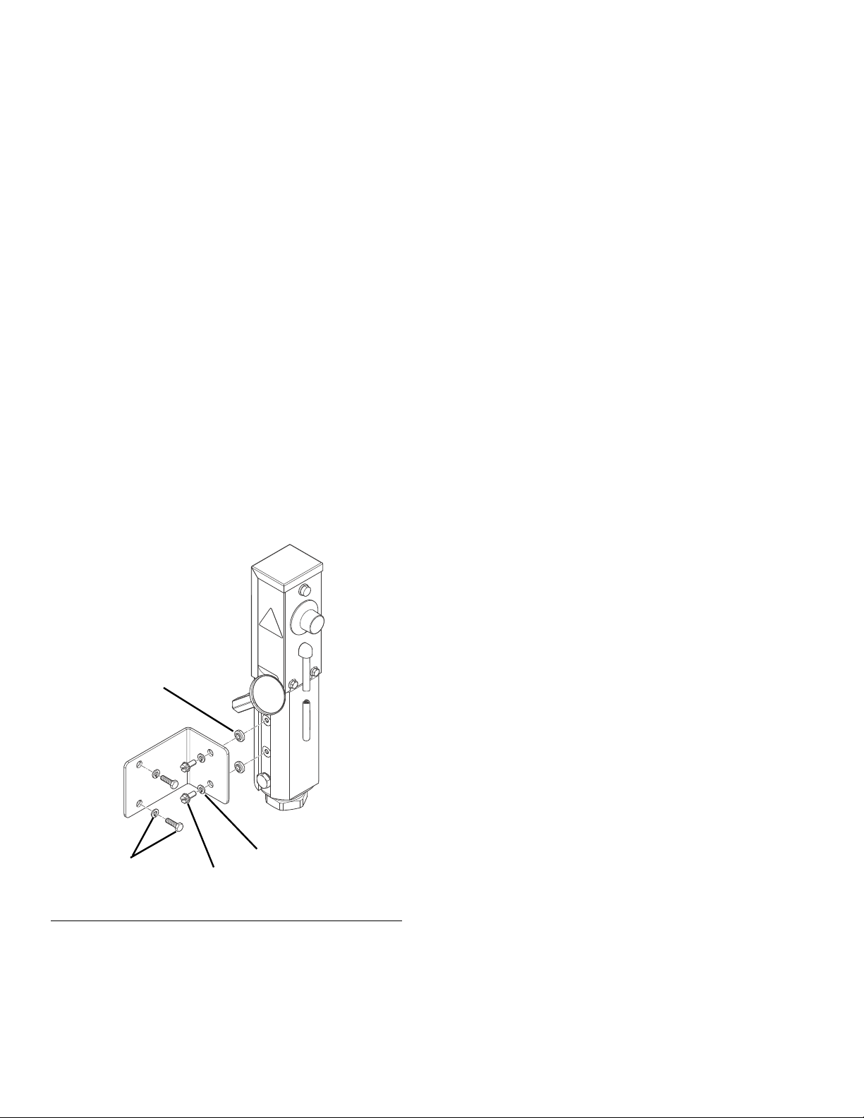
Mounting Heater
Heater controls must be easily accessible.
The mounting surface must be able to support the
weight of the heater and fluid, and any stress caused
during operation.
Wall Mounting
Use included wall bracket 16R988 and insulating
washers (29), part number 167002, quantity 2. See FIG.
4.
Use wall bracket as a template to mark bolt holes.
Bracket 16R988
(FIG.4)
1. Use 1/4 in. bolts of appropriate length and
lock-washer (CC), not supplied, to mount bracket.
2. Use two screws (32) and washers (31) to install
heater onto bracket.
29
ti20000a
CC
32
31
FIG.4:
8 3A2824B
Page 9

Fluid Connections and Accessories
To prevent serious injury caused by component or
equipment rupture:
• Never install a shutoff device between the heater
and gun as this will trap the heated fluid and not
allow for expansion.
• Never use a fluid regulator as a shutoff device if it
is installed between the heater and gun
• Provide a means for adequately handling fluid
expansion caused by heat.
To handle fluid expansion caused by heat:
Component Identification
• Use flexible hoses between heater and gun.
• Install a properly sized accumulator down-
stream from the heater.
• Install a pressure relief valve (X) pre-set to
relieve pressure when it exceeds the system
maximum working pressure.
3A2824B 9
Page 10
Component Identification
Electrical Connections
This equipment must be grounded. All electrical wiring
must be done by a qualified electrician and comply with
all local codes and regulations.
NOTICE
To help prevent heater damage, avoid spilling liquids
onto electrical components.
Requirements For All Installations
• The user must provide external over-current protection. For installations in the United States and Canada, a branch circuit breaker must be used for
over-current protection. The maximum recommended circuit breaker size is 15 amps.
Green or Green/Yellow
Power Cable Connections
The heater power cable uses a 3 conductor cable and a
NEMA L6-20P twist lock connector. If another connector
is used, follow the table below for correct wiring.
Cable Color Code Function
Black or Brown
White or Blue
Green or Green/Yellow
Line (Mains)
Neutral
Protective
Ground/Earth
FIG. 5: Connector
White or Blue
Black or Brown
ti20030a
10 3A2824B
Page 11
Operation
Operation
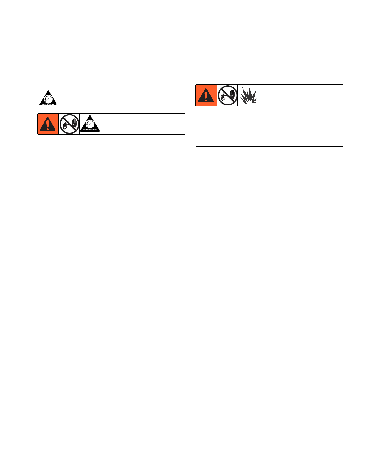
Pressure Relief Procedure
Follow the Pressure Relief Procedure whenever
you see this symbol.
This equipment stays pressurized until pressure is
manually relieved. To help prevent serious injury from
pressurized fluid, such as skin injection, splashing
fluid and moving parts, follow the Pressure Relief
Procedure when you stop spraying and before
cleaning, checking, or servicing the equipment.
Follow Pressure Relief Procedure when you stop
spraying, and before cleaning, checking, or servicing
equipment.
1. Engage the gun trigger lock.
2. Shut off main power to the heater.
3. Circulate fluid for at least 10 minutes to cool the
heated fluid and heater.
4. Shut off all air and fluid supplies.
5. Disengage the gun trigger lock.
6. Hold a metal part of the gun firmly to a grounded
metal pail, and trigger the gun to relieve pressure.
7. Engage the gun trigger lock.
Initial Flushing
To avoid skin injection, do not point gun at anyone or
at any part of the body. To avoid fire and explosion,
ensure main power is off and heater is cool before
flushing. Do not turn on heater until fluid lines are
clear of solvent.
The heater was tested with lightweight oil, which needs
to be flushed out before using the equipment. Use a
compatible solvent, and follow flushing instructions in
your fluid supply and spray gun manual.
Priming System
(Refer to FIG.1,page5)
1. Do not turn on the heater yet.
2. If using an airless spray gun, do not install a spray
tip yet.
3. Start the pump according to the instructions supplied with it.
4. Turn the system director valve (U) to circulate, and
circulate fluid for several minutes.
5. Open the spray gun (Q) at the last outlet to prime
the line. Repeat for all gun stations.
6. Engage the gun trigger lock.
7. Shut off the air supply to the pump.
8. Perform Pressure Relief Procedure.
9. Install the gun spray tip.
3A2824B 11
Page 12
Operation
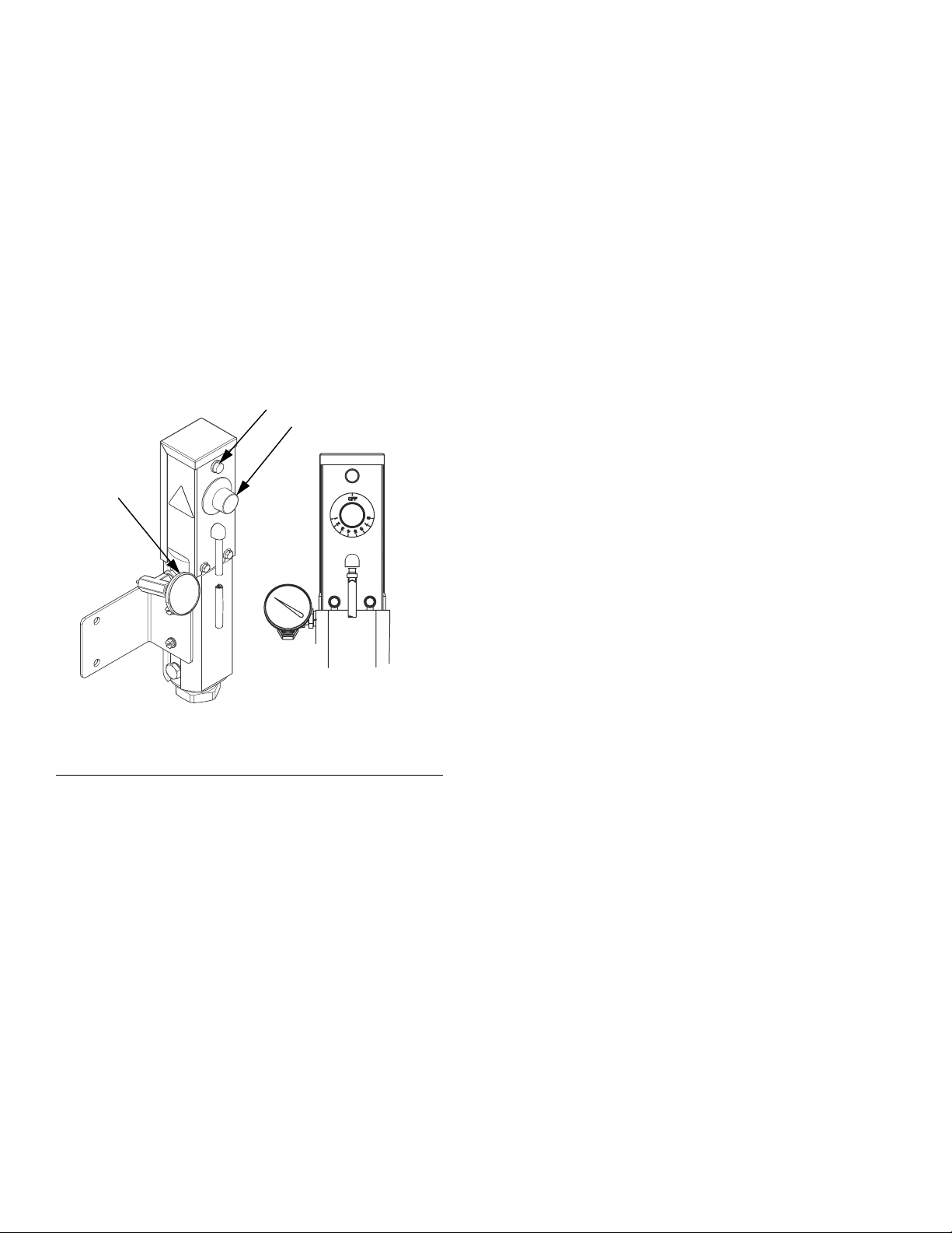
Setting Heater Control
(Refer to FIG.6)
1. Set the heater control knob (9) to a trial setpoint of 4
or 5.
2. Start the pump and circulate fluid through the system at a very low flow rate of about 10-12 oz/min
(0.30-0.35 liter/min).
3. After the red heater light (AB) turns off, read the
temperature on the thermometer (38). If it does not
match the desired temperature, adjust the setpoint.
AB
9
35
F
IG. 6: Setting Heater Control
ti20002a
12 3A2824B
Page 13
Troubleshooting
Troubleshooting
PROBLEM CAUSE SOLUTION
No heat and heater indicator light is
off.
No heat but heater indicator light is
on.
Heat but heater indicator light is off. Bad light. Check connections. Replace lamp.
Heater power off or circuit breaker
tripped.
Bad thermostat (17). With power on, check for continuity
Bad overtemperature sensor (19).
This is a high temperature limit fuse
and must be replaced if blown.
Bad heater cartridge (20). With power OFF, check for continuity
Turn heater power on or reset circuit
breaker.
on/off at clicks when turning the
heater control knob. To replace thermostat, see page 16.
With power on, check for continuity at
overtemperature sensor. To replace
sensor, see page 15.
at heater cartridge connections which
should be 29-36 ohms.
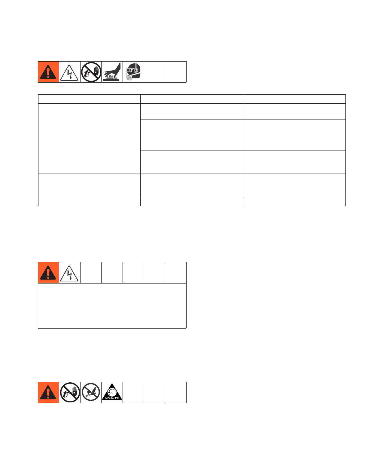
Repair
Before Beginning Repair
Repairing this equipment requires access to parts
which may cause electric shock or other serious injury
if work is not performed properly. Have a qualified
electrician connect power and ground to main power
switch terminals. Be sure to shut off all power to the
equipment before repairing.
1. Flush if necessary.
2. Shut off all power to equipment.
3. Perform Pressure Relief Procedure, page 11.
3A2824B 13
Page 14
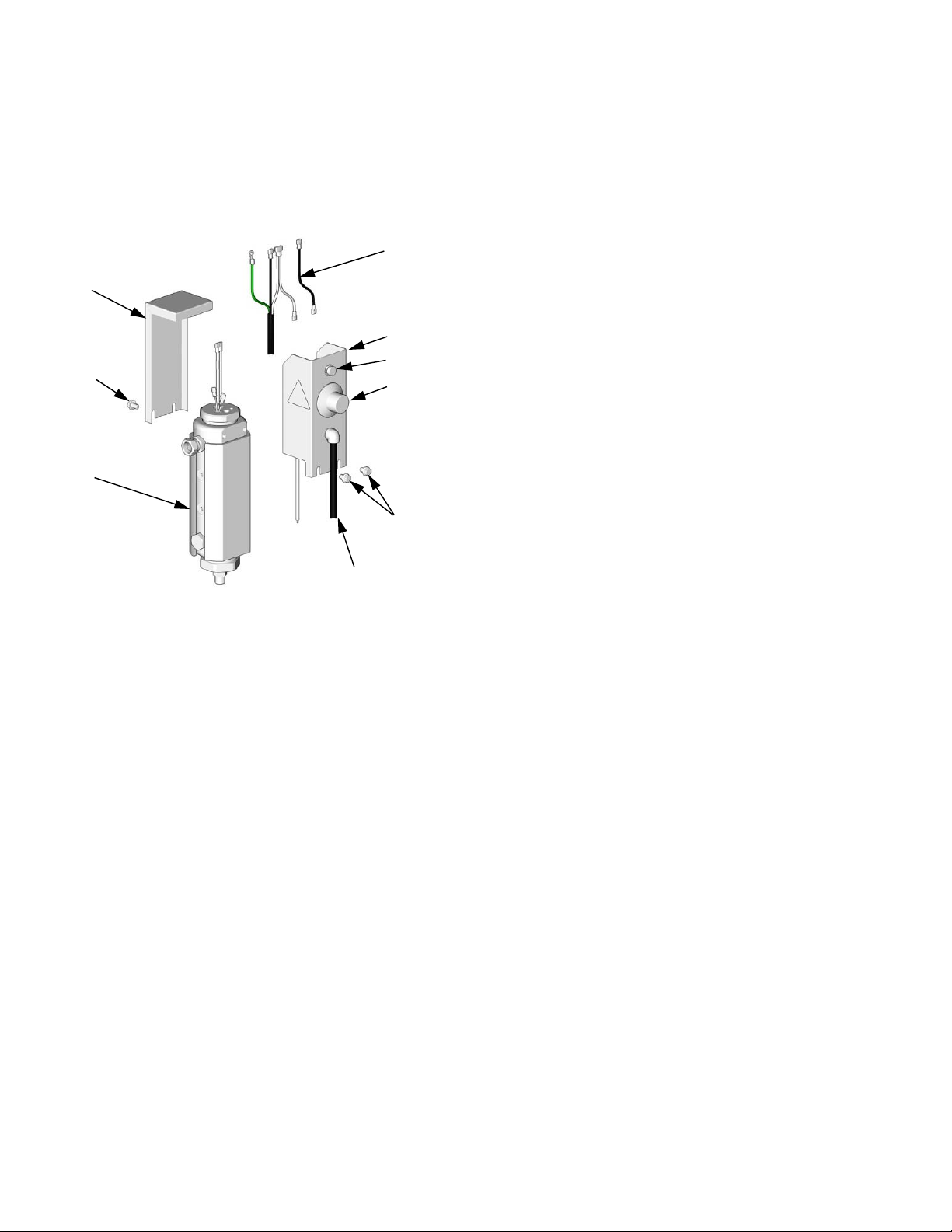
Repair
Heater Temperature Controls
See FIG. 7. Control knob (9) sets temperature of heater.
Indicator light (8) turns on when thermostat is heating
and off when heater reaches setpoint.
22
21
17
12
1
8
9
F
IG.7
ti7008b
12
Power in
14 3A2824B
Page 15
Repair
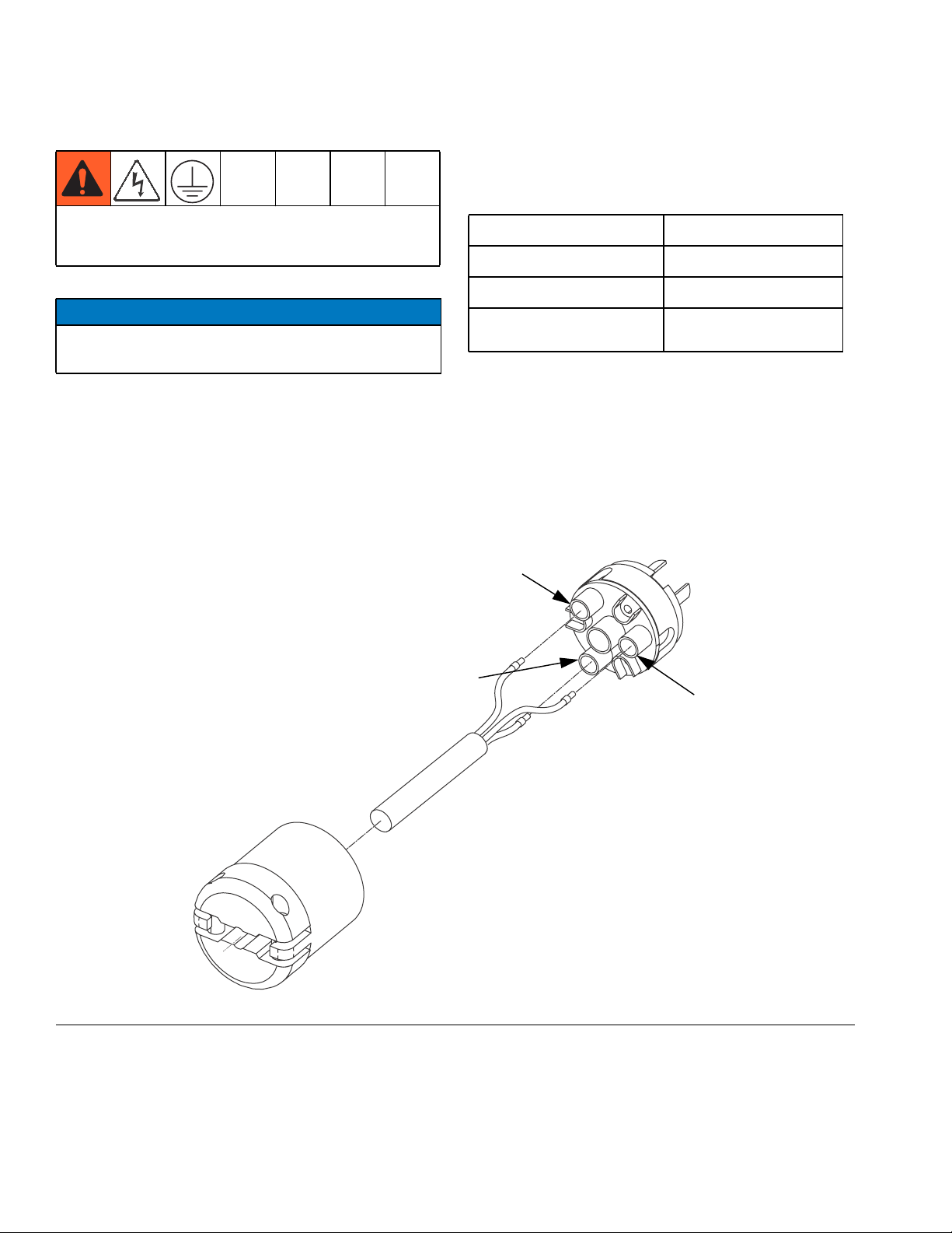
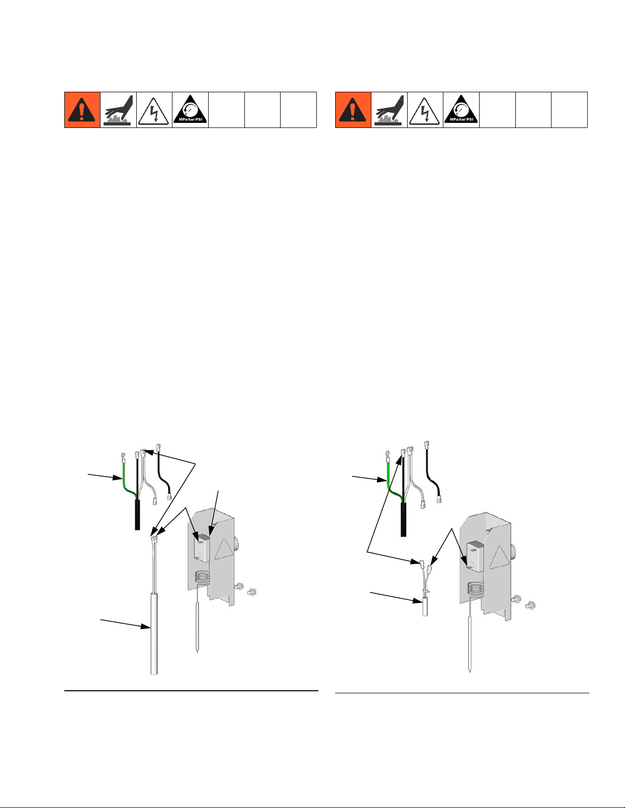
Heater Cartridge
1. See Before Beginning Repair, page 14. Relieve
pressure.
2. Wait for heaters to cool.
3. Testing: Use a multimeter to check resistance
across cartridge leads per the Technical Data
chart. Also check that neither lead has continuity to
the cartridge case.
4. See FIG. 7 and Parts illustration on page 18.
Loosen all four screws (12) from bracket (16) and
shield (21). Pull bracket assembly away from heater
housing (1) to remove heater cartridge (20) from
core. If necessary, plug (4) can be removed from the
bottom of core (2) so that cartridge can be pushed
out from underneath.
5. Disconnect heater cartridge from jumper
wires (22, CC) and heater thermostat switch (17,
HH). See FIG.8.
6. Connect new heater cartridge to jumper wire (CC)
and thermostat heater switch (H), then reassemble
heater in reverse order of disassembly.
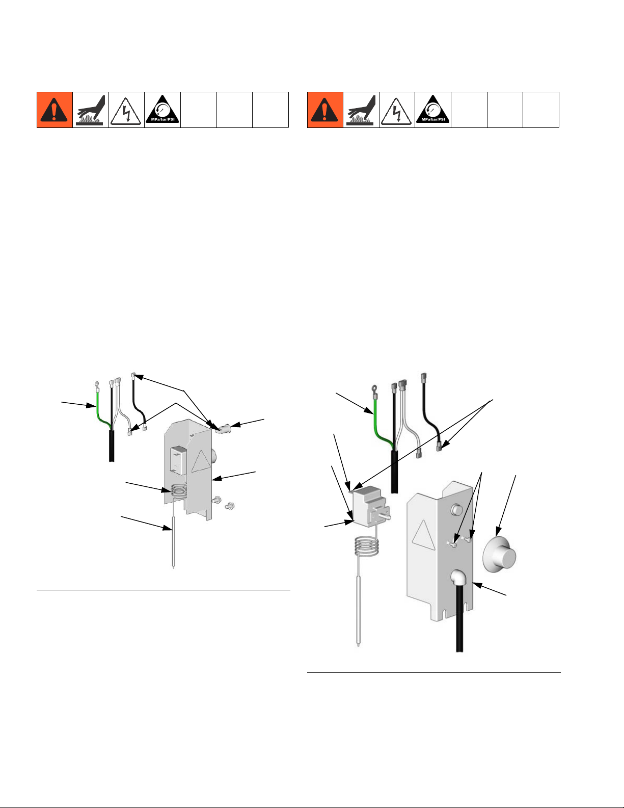
Thermal Limit Sensor
1. See Before Beginning Repair, page 14. Relieve
pressure.
2. Wait for heaters to cool.
3. Testing: Check that you have continuity across the
two leads. If circuit is open, replace thermal limit
sensor (19). See FIG.9
4. See FIG. 7. Loosen all four screws (12) from
bracket (16) and shield (21). Pull bracket assembly
away from heater housing (1). To remove thermal
limit sensor (19) from core (2) pull upward with a
steady force.
5. Disconnect thermal limit sensor from jumper
wire (23, BB) and heater thermostat switch (17,
GG). See FIG.9.
6. Connect new thermal limit sensor to jumper
wire (BB) and thermostat switch (GG), then reassemble heater in reverse order of disassembly.
NOTE: Apply a thin film of heat sink compound 110009
to thermal limit sensor (19).
22
FIG.8
20
HH
CC
17
TI7009a
23
GG
BB
19
TI7010a
FIG.9
3A2824B 15
Page 16
Repair
Indicator Light
1. See Before Beginning Repair, page 14. Relieve
pressure.
2. Wait for heaters to cool.
3. See FIG. 7. Loosen two screws (12) and remove
shield (21).
4. Disconnect jumper wires (23, DD, EE) from back of
indicator light (9), then push light out through the
front face of the control bracket (17) by depressing
the prongs on the sides of the light. See FIG.10.
5. Press new light into control bracket (16) until prongs
lock in place.
6. Connect jumper wires (DD, EE) and reassemble
heater in reverse order of disassembly.
Heater Thermostat Switch
1. See Before Beginning Repair, page 14. Relieve
pressure.
2. Wait for heaters to cool.
3. Testing: See FIG. 10. With thermostat probe (JJ)
above 75°F (24°C), and below 160°F (71°C), the
continuity across the contacts should open when
turned off, and close when turned up toward 8. You
should hear the switch click open and closed.
4. See FIG. 7. Loosen two screws (12) and remove
shield (20).
5. See FIG. 11. Detach the two push on connectors
from thermostat switch (17). One is from thermal
limit sensor (19) at GG, and dual connector HH and
FF is from heater cartridge (21) and light (8).
22
FIG.10
KK
JJ
DD
EE
8
16
TI7011a
22
HH
GG
17
FIG.11
25
FF
9
16
TI7012a
6. Pull heater control knob (9) off of heater control
bracket (16) face.
7. Using a phillips head screwdriver, remove
screws (25) on control bracket face to release ther-
16 3A2824B
Page 17
Repair
mostat switch from bracket. Pull thermostat
probe (JJ) slowly out of heater core (2).
8. Insert new thermostat probe into core with heat sink
compound 110009. Use screws (25) to install new
thermostat switch behind bracket face and install
control knob.
9. Reattach jumper wires (22) and reassemble heater
in reverse order of disassembly.
• Stretch thermostat probe coils (KK) down to
contact top of core. Route wires from thermal
limit switch (19), heater cartridge (20), and
ground wire through center of coils.
• Bend tabs on thermostat away from each other
after installing wire connectors so they do not
interfere with shield (21).
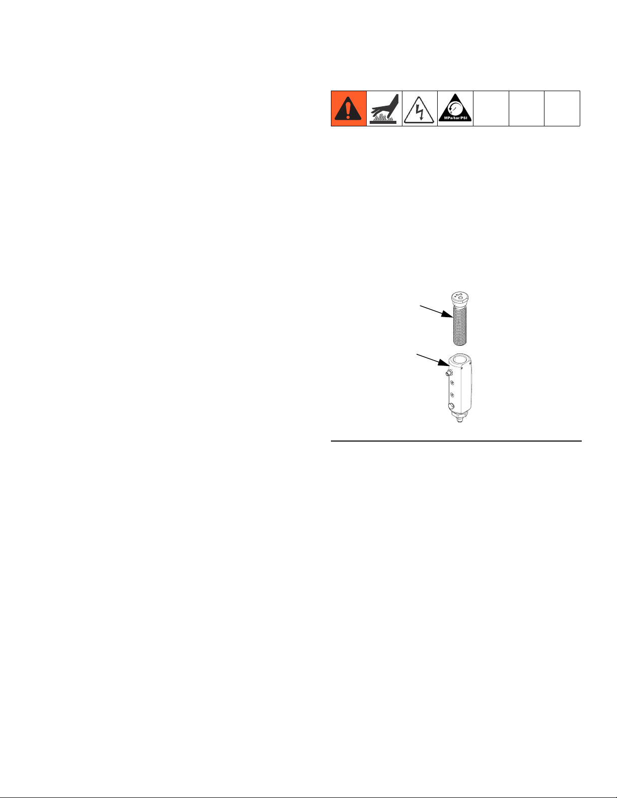
Cleaning Heater Core
1. See Before Beginning Repair, page 14. Relieve
pressure.
2. Wait for heaters to cool.
3. Loosen four screws (12) then pull control section up
out of the way.
4. See FIG. 12. Unscrew core (2) from housing (1).
Use wire brush to clean core then re-install in housing.
2
1
FIG.12
ti20004a
3A2824B 17
Page 18
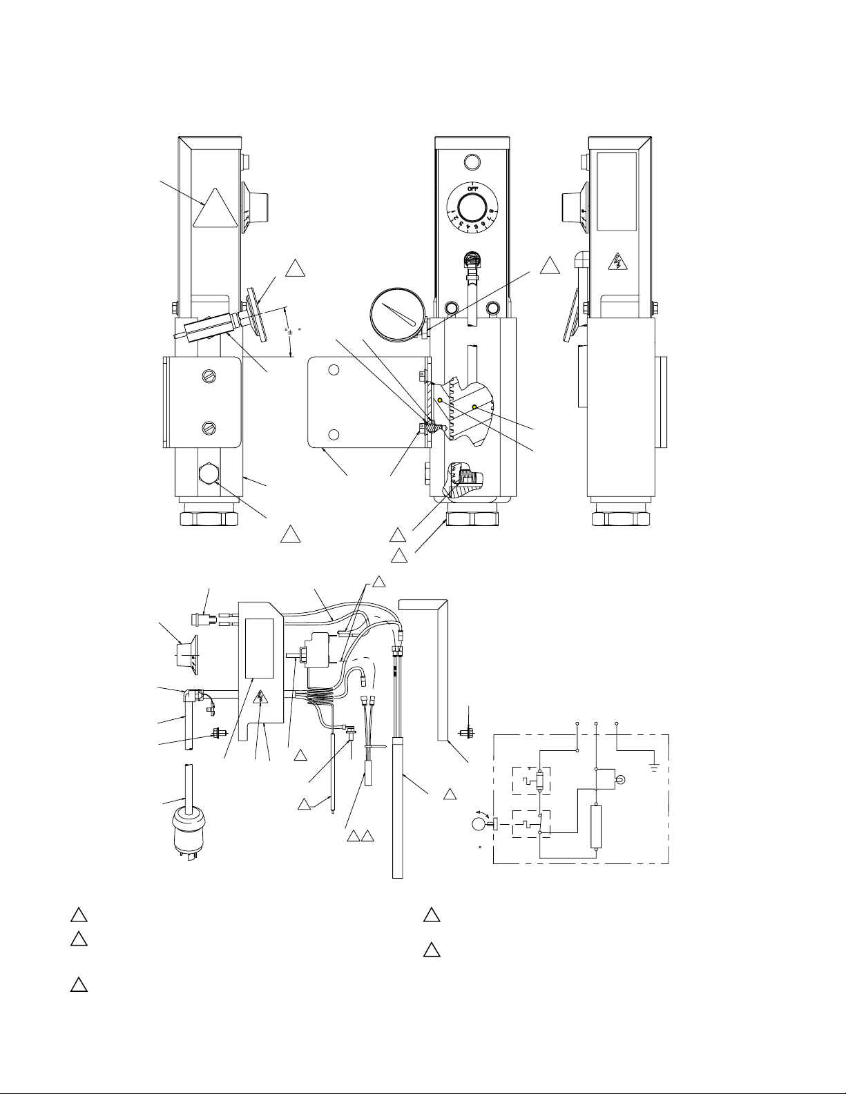
Parts
Parts
;
;
;
723
..
Green/
Yellow
;
1
Apply a thin film of heatsink compound (26).
2
Stretch capillary coils (KK) down to contact top of core (2).
Route wires from thermal limit switch (19), heater
cartridge (20) and ground wire through center of coils.
7
Apply both tape (27) and sealant (28) to all pipe threads.
Brown
Blue
;
Power from
Control Box
OFF
&
9
Bend tabs on thermostat away from each other after installing
wire connectors so cover cannot contact wires.
12
Apply lubricant to o-ring (40).
&
Brown
)
Blue
Green/
Yellow
240 V
Lamp
5
240 V
1750 Watt
18 3A2824B
Page 19

Accessories
Ref Part Description Qty
1 24K987 HOUSING, heater 1
2 24K988 CORE, heater, spiral 1
3 24K992 INSULATOR, heater 1
4 101754 PLUG, pipe 1
5 24K991 BUSHING, reducing, 1-1/5 x 3/8 1
7 166863 FITTING, nipple, reducing 1
8 114286 LIGHT, indicator, 240V 1
9 24K979 KNOB, control, heater 1
10 119924 BUSHING, strain relief, 90 degree 1
11 16T187 HARNESS, power, heater 1
12 --- SCREW, machine, hex serrated 4
13 --- LABEL, identification 1
15▲ 189930 LABEL, electric shock, triangular 1
16 249521 BRACKET, heater control 1
17 24K978 SWITCH, thermostat, heater 1
18 116343 SCREW, ground 1
19 24K980 SENSOR, thermal limit, 152C, QD 1
20 16T173 CARTRIDGE, heater, 1750W,
240V
21 249520 SHIELD, heater control 1
22 119858 WIRE, jumper, heater 1
23▲ 189285 LABEL, burn hazard, triangular 1
24 172953 LABEL, designation 1
25 195874 SCREW, machine, phillips pan
head
26 110009 LUBRICANT, thermal, 1 oz tube 1
29 167002 INSULATOR, heat 2
30 16R989 BRACKET, heater 1
31 100016 WASHER, lock 2
32 108296 SCREW, machine, hex washer
head
33 113914 FITTING, tee, 1/4 npt, female 1
35 102124 THERMOMETER, dial 1
39 198241 PLUG, port, pressure 1
40 111457 O-RING 1
99 16T174 PLUG, electrical, locking, L6-20P 1
Accessories
110009 Heat sink compound, 1 oz. tube
1
2
2
--- Not for sale.
▲ Replacement Danger and Warning labels, tags and
cards are available at no cost.
◆ Not shown.
3A2824B 19
Page 20

Technical Data
Technical Data
Maximum Working Pressure ...................... 2000 psi (140 bar, 14 MPa)
Maximum Amps ................................ 7.3A
Maximum Fluid Temperature ...................... 180°F (82°C)
Voltage....................................... 240VAC,1750 Watts
Heater Resistance .............................. 29to36ohms
Heated Core Area ..............................
68 in.
2
(438 cm
FluidPath..................................... 3parallelpaths,40in.each
Pressure Drop ................................. Equivalent to 40 in. of 1/4 in. (6.3 mm) ID hose
Inlet ......................................... 3/8npt(f)
Outlet........................................ 1/4npt(f)
Weight ....................................... 9.0lb(4.1kg)
WettedParts .................................. Anodized aluminum, zinc-plated steel, stainless
steel, PTFE
Schematic Diagram
Power from
Control Box
Brown
Blue
2)
Green/
Yellow
OFF
90°C
127°C
R1
120 Volt
850 Watt
Or
240 Volt
1000 Watt
120V or
240V Lamp
F
20 3A2824B
Page 21

Dimensions
Technical Data
1/4 npsm Fluid Outlet
2.9 in.
(7.3 cm)
2.5 in.
(6.35 cm)
15.3 in.
(38.7 cm)
70 in. (178 cm) SJTO cable
with NEMA L6-20P twist
lock connector
3/8 npt(f) Fluid Inlet
ti19998a
3A2824B 21
Page 22

Graco Standard Warranty
Graco warrants all equipment referenced in this document which is manufactured by Graco and bearing its name to be free from defects in
material and workmanship on the date of sale to the original purchaser for use. With the exception of any special, extended, or limited warranty
published by Graco, Graco will, for a period of twelve months from the date of sale, repair or replace any part of the equipment determined by
Graco to be defective. This warranty applies only when the equipment is installed, operated and maintained in accordance with Graco’s written
recommendations.
This warranty does not cover, and Graco shall not be liable for general wear and tear, or any malfunction, damage or wear caused by faulty
installation, misapplication, abrasion, corrosion, inadequate or improper maintenance, negligence, accident, tampering, or substitution of
non-Graco component parts. Nor shall Graco be liable for malfunction, damage or wear caused by the incompatibility of Graco equipment with
structures, accessories, equipment or materials not supplied by Graco, or the improper design, manufacture, installation, operation or
maintenance of structures, accessories, equipment or materials not supplied by Graco.
This warranty is conditioned upon the prepaid return of the equipment claimed to be defective to an authorized Graco distributor for verification of
the claimed defect. If the claimed defect is verified, Graco will repair or replace free of charge any defective parts. The equipment will be returned
to the original purchaser transportation prepaid. If inspection of the equipment does not disclose any defect in material or workmanship, repairs will
be made at a reasonable charge, which charges may include the costs of parts, labor, and transportation.
THIS WARRANTY IS EXCLUSIVE, AND IS IN LIEU OF ANY OTHER WARRANTIES, EXPRESS OR IMPLIED, INCLUDING BUT NOT LIMITED
TO WARRANTY OF MERCHANTABILITY OR WARRANTY OF FITNESS FOR A PARTICULAR PURPOSE.
Graco’s sole obligation and buyer’s sole remedy for any breach of warranty shall be as set forth above. The buyer agrees that no other remedy
(including, but not limited to, incidental or consequential damages for lost profits, lost sales, injury to person or property, or any other incidental or
consequential loss) shall be available. Any action for breach of warranty must be brought within two (2) years of the date of sale.
GRACO MAKES NO WARRANTY, AND DISCLAIMS ALL IMPLIED WARRANTIES OF MERCHANTABILITY AND FITNESS FOR A
PARTICULAR PURPOSE, IN CONNECTION WITH ACCESSORIES, EQUIPMENT, MATERIALS OR COMPONENTS SOLD BUT NOT
MANUFACTURED BY GRACO. These items sold, but not manufactured by Graco (such as electric motors, switches, hose, etc.), are subject to
the warranty, if any, of their manufacturer. Graco will provide purchaser with reasonable assistance in making any claim for breach of these
warranties.
In no event will Graco be liable for indirect, incidental, special or consequential damages resulting from Graco supplying equipment hereunder, or
the furnishing, performance, or use of any products or other goods sold hereto, whether due to a breach of contract, breach of warranty, the
negligence of Graco, or otherwise.
FOR GRACO CANADA CUSTOMERS
The Parties acknowledge that they have required that the present document, as well as all documents, notices and legal proceedings entered into,
given or instituted pursuant hereto or relating directly or indirectly hereto, be drawn up in English. Les parties reconnaissent avoir convenu que la
rédaction du présente document sera en Anglais, ainsi que tous documents, avis et procédures judiciaires exécutés, donnés ou intentés, à la suite
de ou en rapport, directement ou indirectement, avec les procédures concernées.
Graco Information
For the latest information about Graco products, visit www.graco.com.
TO PLACE AN ORDER, contact your Graco distributor or call to identify the nearest distributor.
Phone: 612-623-6921 or Toll Free: 1-800-328-0211 Fax: 612-378-3505
All written and visual data contained in this document reflects the latest product information available at the time of publication.
GRACO INC. AND SUBSIDIARIES • P.O. BOX 1441 • MINNEAPOLIS MN 55440-1441 • USA
Copyright 2012, Graco Inc. All Graco manufacturing locations are registered to ISO 9001.
Graco reserves the right to make changes at any time without notice.
For patent information, see www.graco.com/patents.
2ULJLQDOLQVWUXFWLRQV This manual contains English. MM 3A2824
Graco Headquarters: Minneapolis
International Offices: Belgium, China, Japan, Korea
www.graco.com
Revised February 2013
 Loading...