

Page 1
Instructions - Parts
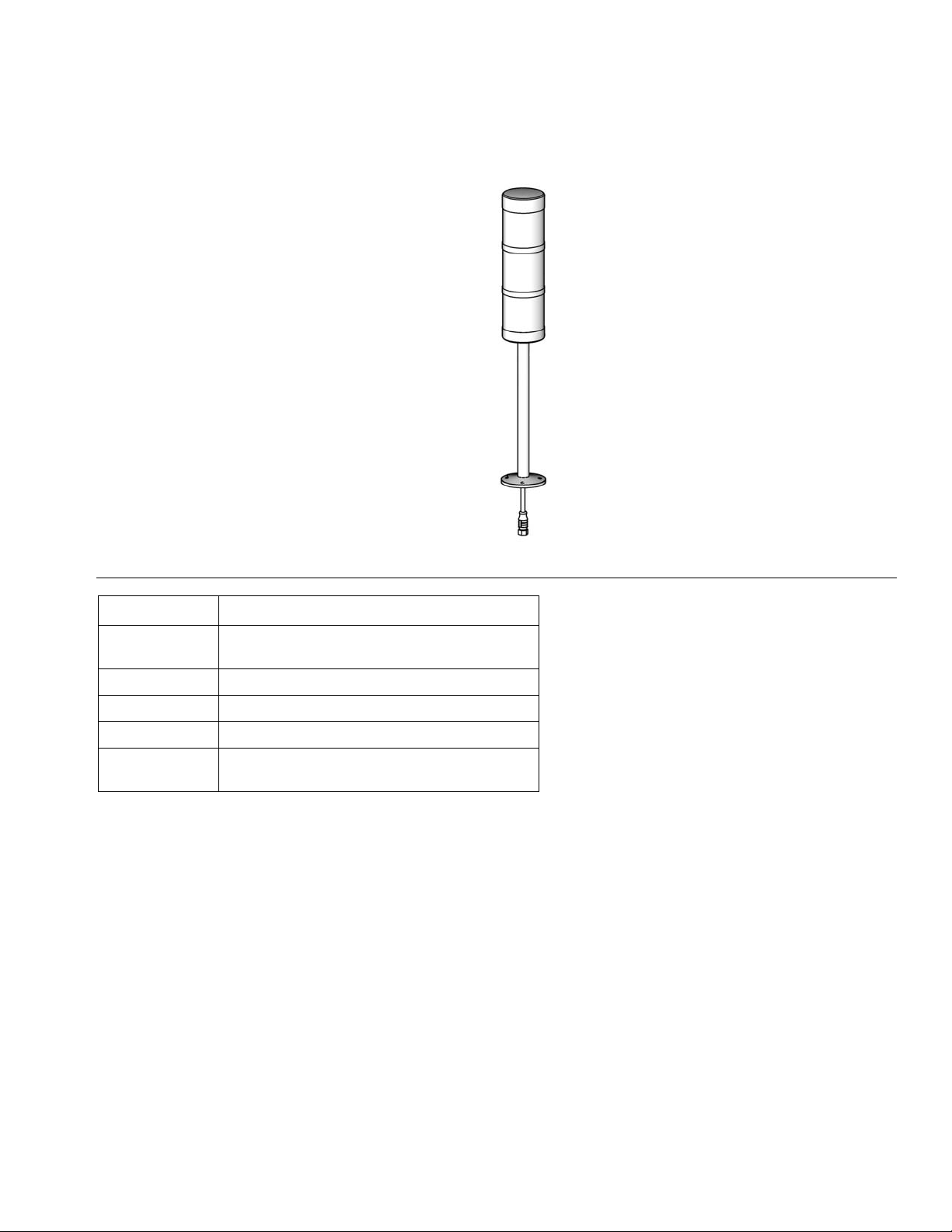
Level Detection Module
3A2806C
and Drum Feed Kit
Installation kit to provide low level sensors in both chemical sides of an HFRL or HFRS
plural-component proportioner being fed from 55 gallon (208 liter) drums. Not for use with
standard configured HFR units. For professional use only.
Not approved for use in explosive atmospheres or hazardous locations.
Important Safety Instructions
Read all warnings and instructions in the HFRL and HFRS
Setup-Operations manual. Save all instructions.
EN
See page 3 for model information.
125 psi (0.86 MPa, 8.6 bar) Maximum Fluid Working Pressure
125 psi (0.86 MPa, 8.6 bar) Maximum Air Input Pressure
ti19596a
Page 2

Contents
Related Manuals . . . . . . . . . . . . . . . . . . . . . . . . . . . 3
Models . . . . . . . . . . . . . . . . . . . . . . . . . . . . . . . . . . . 3
Component Identification . . . . . . . . . . . . . . . . . . . . 4
Complete Feed System . . . . . . . . . . . . . . . . . . . . 4
Electrical Panel Components . . . . . . . . . . . . . . . 5
Fluid Control Module (FCM) . . . . . . . . . . . . . . . . 6
Light Tower . . . . . . . . . . . . . . . . . . . . . . . . . . . . . 7
Grounding . . . . . . . . . . . . . . . . . . . . . . . . . . . . . . . . 8
Flush Pumps Before Using . . . . . . . . . . . . . . . . . . . 8
Installation . . . . . . . . . . . . . . . . . . . . . . . . . . . . . . . . 9
Install 4 Drum Rack (Optional) . . . . . . . . . . . . . . 9
Refer to 4 Drum Rack, 01/0955/25 (Optional) on
page 30 for visual clarity. . . . . . . . . . . . . . . . 9
Position Drums . . . . . . . . . . . . . . . . . . . . . . . . . . 9
Install Drum Feed Kit . . . . . . . . . . . . . . . . . . . . . . 9
Connect Feed Pump . . . . . . . . . . . . . . . . . . . . . . 9
Install Electrical Panel . . . . . . . . . . . . . . . . . . . . 10
Install Level Sensors . . . . . . . . . . . . . . . . . . . . . 12
Install Light Tower . . . . . . . . . . . . . . . . . . . . . . . 13
Setup . . . . . . . . . . . . . . . . . . . . . . . . . . . . . . . . . . . . 14
Calibrate Barrel Style Level Sensors . . . . . . . . . 14
Set the ADM to Recognize the Feed System Kit 14
Set the ADM to Recognize which Level Sensors are
to Operate . . . . . . . . . . . . . . . . . . . . . . . . . . 15
Set the Level Sensors Output Function . . . . . . 15
Startup . . . . . . . . . . . . . . . . . . . . . . . . . . . . . . . . . . 16
Shutdown . . . . . . . . . . . . . . . . . . . . . . . . . . . . . . . . 16
Pressure Relief Procedure . . . . . . . . . . . . . . . . . . 16
Maintenance . . . . . . . . . . . . . . . . . . . . . . . . . . . . . . 16
Drum Feed Kit - Air Dryer . . . . . . . . . . . . . . . . . 16
Drum Feed Kit, Pump . . . . . . . . . . . . . . . . . . . . 17
Drum Feed Kit, Changing Top Drums . . . . . . . . 17
Install Upgrade Tokens . . . . . . . . . . . . . . . . . . . 18
Troubleshooting . . . . . . . . . . . . . . . . . . . . . . . . . . . 19
Repair . . . . . . . . . . . . . . . . . . . . . . . . . . . . . . . . . . . 20
Level Sensor and Well . . . . . . . . . . . . . . . . . . . . 20
Electrical Schematics . . . . . . . . . . . . . . . . . . . . . . 21
Parts . . . . . . . . . . . . . . . . . . . . . . . . . . . . . . . . . . . . 22
Drum Feed System, 24N816 . . . . . . . . . . . . . . . 22
Drum Feed Kit, 24N767 . . . . . . . . . . . . . . . . . . . 24
Electric Panel, 24N804 . . . . . . . . . . . . . . . . . . . 26
4 Drum Rack, 01/0955/25 (Optional) . . . . . . . . . 30
Appendix A - ADM Setup Screens Overview . . . . 32
Appendix B - ADM Run Screens Overview . . . . . 35
Technical Data . . . . . . . . . . . . . . . . . . . . . . . . . . . . 37
Graco Standard Warranty . . . . . . . . . . . . . . . . . . . 38
2 3A2806C
Page 3

Related Manuals
Component manuals in English. Manuals are available
at www.graco.com.
Manual No. Description
3A2175 HFRL and HFRS, Setup-Operations
3A2176 HFRL and HFRS, Repair-Parts
312877 Husky 1050 Air-Operated Diaphragm Pump, Operation
3A0235 Feed Supply Kits, Instructions-Parts
406987 GCA CAN Cables, Reference (Extension Cables)
Models
NOTE: Not for use with standard HFR units.
Related Manuals
Part
24N816
24N767
01/0955/25 4 Drum rack (Optional)
Description
KIT, low level, stack light, HFRL (Required):
- (2) low level sensors - (1) sensor per chemical side
- (1) control panel for level sensors
- (1) indicator stack light
Carbon steel drum feed kit with Husky pump (Optional):
- Kit is to add a drum feed to (1) chemical side
3A2806C 3
Page 4
Component Identification
Component Identification
Complete Feed System
Figure Shown With:
(1) Level Kit
(2) Drum Feed Kit Options
(1) 4 Drum Rack Option
G
F
D
E
B
C
A
ti19596a
KJ H
FIG. 1: Component Identification - Feed System
Key:
A Auxiliary Control Panel (Mounted in Machine Base)
Refer to F
B Level Sensor - Low Level Indication
C Level Sensor - Empty Indication
D Indicator Stack Light
E Drum Feed / Pump Kit for One Chemical (Optional)
F 4 Drum Rack (Optional)
G Upper to Lower Drum Feed Hose
4 3A2806C
IG. 2
H Drum to Pump Feed Hose, 6 ft (1.8 m)
J Husky Pump
K HFR Supply Hose
Page 5
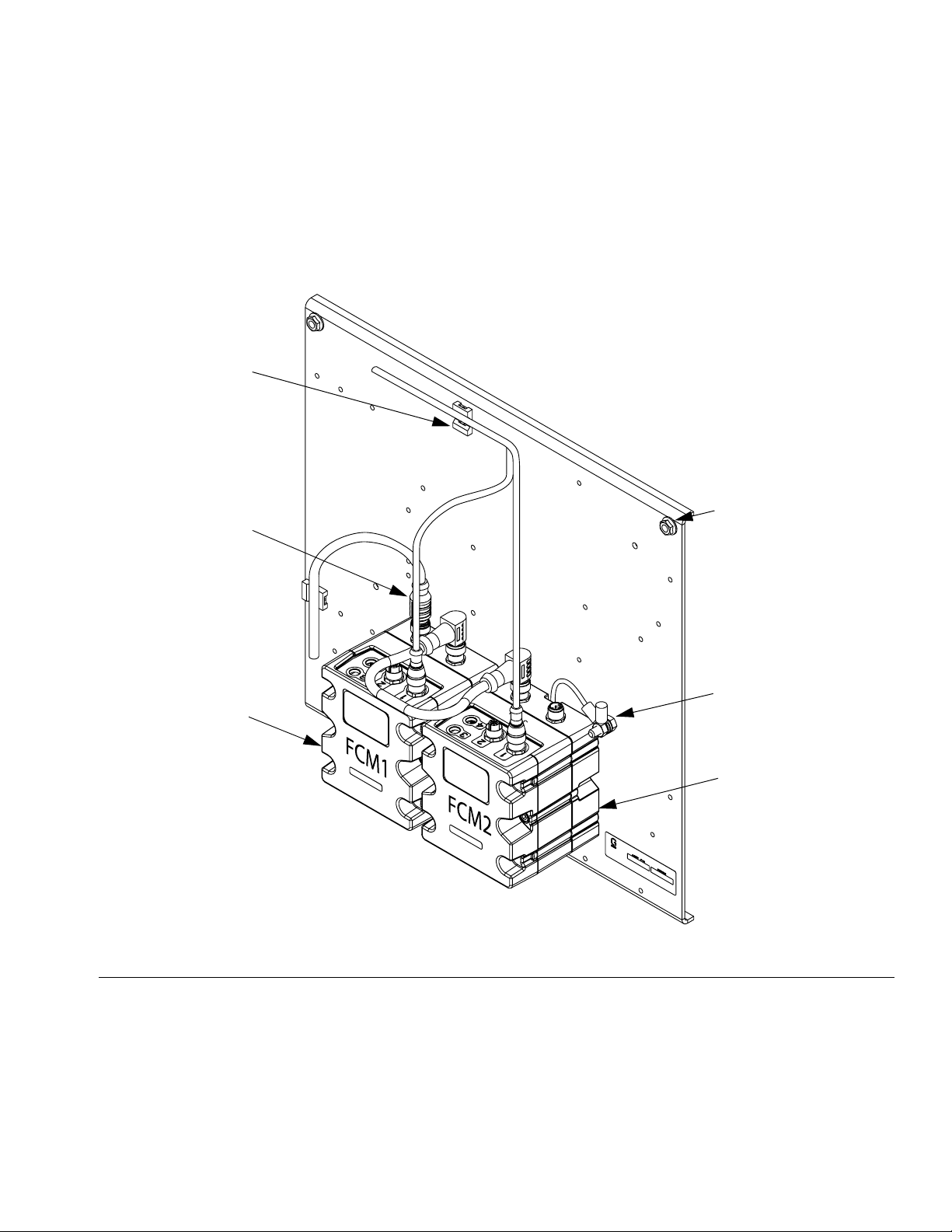
Electrical Panel Components
Component Identification
The electrical panel will be located on the inside of the
HFRL stand enclosure, and includes two fluid control
modules.
AF
AD
Software is loaded on Fluid Control Modules (FCM).
Program token 16G584 is also provided.
AE
AA
FIG. 2: Component Identification - Electrical Panel
Key:
AA Fluid Control Module - A (Red) Tank
AB Fluid Control Module - B (Blue) Tank
AC Ground Cable
AD CAN Cable
AE Flanged Hex Nuts (3x)
AF Wire Tie Anchor
AC
AB
r_24n804
3A2806C 5
Page 6
Component Identification
Fluid Control Module (FCM)
BA
BC
BH
BG
BE
ti12337a
BF
BB
FIG. 3: Component Identification - FCM
Key:
BA Fluid Control Module (FCM)
BB Base
BC Module Connection Screws
BD Access Cover
BE Module Status LEDs
BF CAN Connectors
BG Level Sensor Input
BH Fill Solenoid Signal
Adjust Rotary Switch
The rotary switch setting indicates which zone the fluid
control module will control in the system. The FCM uses
a 16-position rotary switch to make selections.
Set the rotary switch to the specific selection according
to the settings listed in the following table.
ti12336a
BD
Setting Zone
0 through 2 Not Used
3 B (Blue) Tank Level
4 A (Red) Tank Level
5 through F Not Used
Rotary Switch
ti12361a
FIG. 4: Adjust Rotary Switch
6 3A2806C
Page 7
Light Tower
Component Identification
FIG. 5: Component Identification - Light Tower
Signal Description
Green on only System is powered up and there are no error con-
ditions present
Yellow on An advisory exists
Yellow flashing Material is at a low level condition
Red flashing A deviation exists
Red on The system is shut down due to an alarm occur-
ring.
Errors include advisories, deviations, or alarms, so
green will only be on when none of these occur. A yellow
light can be on at the same time as red (flashing or solid
on) when an advisory exists at the same time as a deviation or alarm.
Messaging will be viewable on the ADM to determine
the specific error code.
tower
3A2806C 7
Page 8
Grounding
Grounding
The equipment must be grounded. Grounding reduces
the risk of static and electric shock by providing an
escape wire for the electrical current due to static build
up or in the event of a short circuit.
Pump: follow instructions in separate feed pump manual, supplied.
HFR: see operation manual.
Fluid supply container: follow local code.
Solvent pails used when flushing: follow local code.
Use only conductive metal pails, placed on a grounded
surface. Do not place the pail on a nonconductive surface, such as paper or cardboard, which interrupts
grounding continuity.
To maintain grounding continuity when flushing or
relieving pressure: hold metal part of the spray gun or
dispense valve firmly to the side of a grounded metal
pail, then trigger the gun or valve.
Flush Pumps Before
Using
Flush equipment only in a well-ventilated area. Do
not spray flammable fluids.
NOTICE
Diaphragm pumps are factory tested with water.
Thoroughly flush pumps before using to prevent
moisture contamination when pumping moisture
sensitive materials.
8 3A2806C
Page 9
Installation
Installation
Install 4 Drum Rack (Optional)
NOTICE
To avoid machine damage or personal injury,
anchor the rack to the floor with (4) 1/2” bolts (provided by customer) and verify all bolt assemblies
are tightened before loading the drums onto the
rack.
Refer to 4 Drum Rack, 01/0955/25 (Optional) on
page 30 for visual clarity.
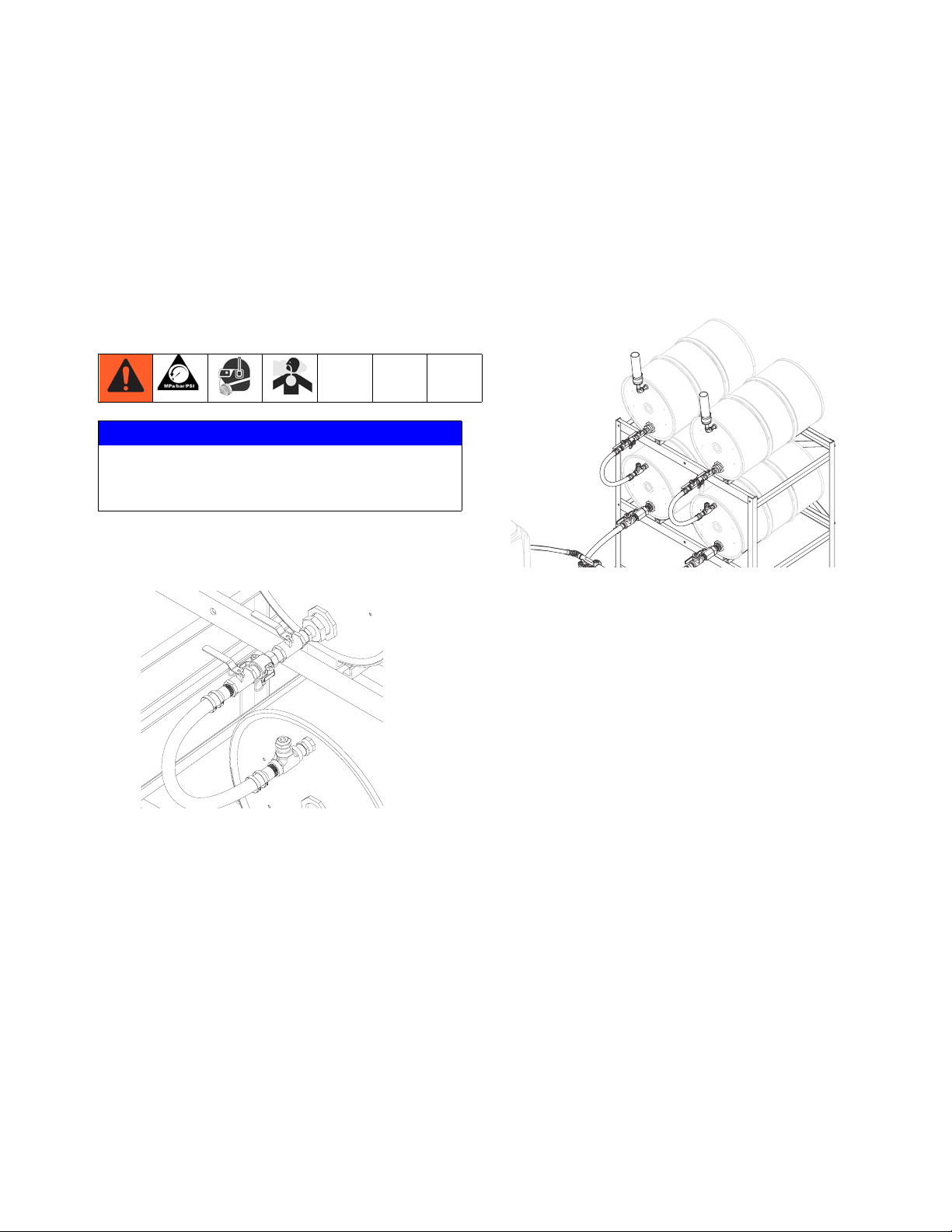
Position Drums
Place component A (red) and component B (blue)
drums as desired. Air hose connecting feed pumps is
15 ft (4.57 m) long.
Fluid hose connecting feed pumps to systems are
10 ft (3.05 m) long.
4. Tighten all connections.
Connect Feed Pump
1. Supply clean, dry, filtered air to feed pumps.
NOTE: Air supply components are not included.
2. Refer to Husky 1050 Air-Operated Diaphragm
Pump, Operation manual for instructions.
Install Drum Feed Kit
NOTICE
To avoid machine damage or personal injury, do not
supply pressure to drums.
1. Complete Setup instructions in the pump manual
before installing in drum feed kit.
NOTICE
To avoid improper operation, the diaphragm pump
must be floor mounted.
2. If applicable, locate drum rack to allow access for
top drum change.
3. Dry fit all hose and fitting components to ensure
components are located properly and will reach the
HFRL. Refer to F
NOTE: Drum to pump feed hose length can be reduced
if necessary. Refer to F
IG. 1, page 4.
IG. 1, page 4, item H.
3A2806C 9
Page 10

Installation
Install Electrical Panel
1. Perform HFR shutdown procedure. See HFRL operation manual for detailed instructions.
2. Disconnect the power supply to the machine.
3. Turn the disconnect switch on the rear base cover of
the machine to the “OFF” position
4. Remove the cover to allow access into the base
cube.
5. Install the pre-assembled panel on the left side of
the cube, directly opposite of the main control panel.
Note the locations of the 3 studs; One in each top
corner, and one in the bottom center.
a. Orient the panel so the mounting holes match
the stud locations of the cube.
b. Insert the panel into the base cube.
8. Remove one of the hole plugs located on the top of
the base cube directly over the disconnect panel
that was just removed.
NOTE: There are three holes on the top edge of the
base cube. The plug can be easily pushed out from
inside the cube.
9. Replace the removed plug with the provided plastic
edge bushing
a. The bushing will snap into place by aligning the
smaller diameter end of the bushing on top of
the hole and pressing the bushing down through
the hole from outside the cube.
10. Insert the male ends of the sensor cords labeled
FCM1A and FCM2B through the bushing and into
the base cube.
11. Connect the cord labeled FCM1A to port “1” (Refer
to F
IG. 2, page 5) on the FCM labeled FCM1.
12. Connect the cord labeled FCM2B to port “1” (Refer
to F
IG. 2, page 5) on the FCM labeled FCM2.
c. Orient the top of the panel such that the studs in
the cube wall extend through the holes in the
top corners of the panel.
d. Fasten the panel to the studs with the (3)
flanged hex nuts provided. Tighten the nuts.
6. Connect the cable (labeled 121002) extending from
the panel to the yellow cable splitter located on the
lower left side of the main machine control panel.
a. Remove the two screws to free the splitter from
the panel.
b. Insert the cable end into the open port on the
splitter and tighten. Note that the plug is keyed
and only fits in the splitter in one orientation.
c. Reattach the splitter to the panel.
7. If there is no available connection on the splitter, an
alternate CAN connection will need to be used. The
alternate location may require a different gendered
cord (122487 is provided for this purpose). Consult
the system manual in finding an alternate connection location.
13. Attached the wire anchor to the inside face of the
base by inserting the provided screw through the
anchor and the weld nut indicated in F
IG. 6. Secure
in place by tightening the hex nut on the screw from
the outside of the base.
14. Secure the cords to the panel and the base cube by
using wire ties (not provided) and the installed plastic anchors.
10 3A2806C
Page 11
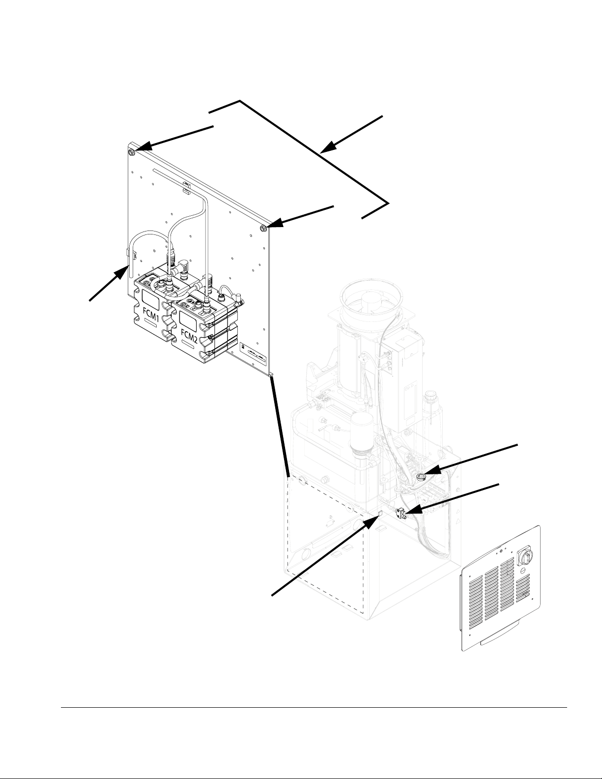
Step 6
Step 5
Installation
NOTE: Mounting location for panel is
only available on HFRL and HFRS
models. This location is used for
other control components on standard HFR models.
Step 5
r_24n804
Panel view is shown rotated 180°
from the installed position.
Step 13
Step 8,
Step 9
Step 6
Panel Install
FIG. 6: Install Electrical Panel
3A2806C 11
Page 12
Installation
Install Level Sensors
NOTE: Lower drum hardware must be installed in an
empty drum and then installed on the lower drum rack.
The drum can then be filled from the cascade feed hose
from a full upper drum.
NOTE: There are two possible locations for the low level
sensor, depending on desired function. Install both sensors in the same location on each chemical side.
• Low Level Indication: Located in the upper to
lower drum feed hose
• Empty Indication: Located in the drum to pump
feed hose.
NOTICE
Do avoid machine damage, install one sensor on
each chemical side only.
where the well is inserted. Note these measurements as they will be need later.
5. Being careful to not cross-threads, thread assembled level sensor (CB) into well housing until it bottoms out against the bottom of the well. The bottom
of the level sensor will be slightly visible through the
bottom of the well.
NOTE: In the following step, do not allow PTFE
paste or tape to cover the tip of the level sensor
well. If paste comes in contact with the tip of the
level sensor well, thoroughly wipe it clean.
6. Apply PTFE paste and PTFE tape to the male
threads of the level sensor well housing.
7. Being careful to not cross-threads, thread the level
sensor well (CA) into the corresponding drum feed
port and lightly tighten with a crescent wrench.
NOTICE
Do not pressurize tank with level sensor removed
from sensor well. Doing so will rupture the level sensor well.
1. Turn main power off.
2. Drain drums below the lowest level sensor well.
NOTE: For proper level sensor function, the tip of
the level sensor well must protrude at least 1/8 in.
into the tank.
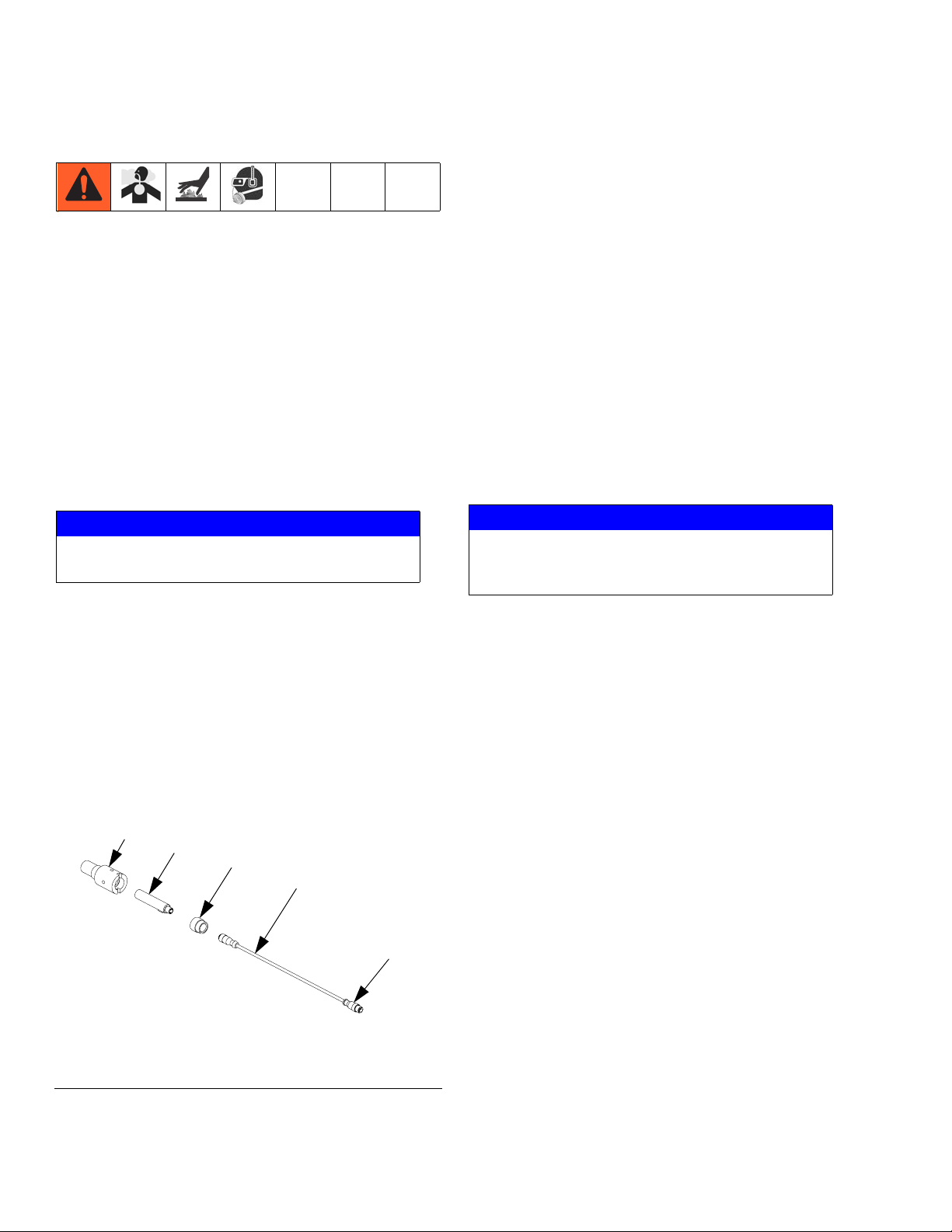
3. Route the level sensor wire through the corresponding well nut (CC). See F
IG. 7 for level sensor assem-
bly view.
CA
CB
CC
Wire
CD
8. The protrusion length must be at least 1/8 in.
(3.2 mm). If not, remove the level sensor well and
restart at step 4.
9. Rotate level sensor such that the cord is pointing
vertical and the sensing face is pointing down.
10. Plug the sensor connector (CD) into the level sensors.
a. Route the sensor wires from the control panel
through the bushing that was installed with the
level sensor panel (steps 8 and 9).
11. Plug the sensor connector into the connector on the
FCM.
12. Calibrate the sensor. See Calibrate Barrel Style
Level Sensors, page 14.
r_24b969_3A0395a_7a-2
FIG. 7: Level Sensor Assembly
4. Measure the length of the level sensor well housing,
and then measure the depth of the hole in the fitting
12 3A2806C
Page 13

Install Light Tower
NOTE: Install the light tower in a suitable location for
clear viewing.
1. Create the hole pattern below to match the light
tower base.
Ø 1.57
Bolt Circle
Ø 0.90
3x 8-32 UNC 2B
Equally Spaced
Mount Pattern
Installation
2. Use the provided screws to attach the light tower to
the mounting bracket.
3. Route the light tower cord as needed towards the
ADM.
NOTICE
To prevent damage to the cord, ensure it will not be
pinched during normal machine operation after
routing.
4. Connect the cable to the port labeled “1” on the
base of the ADM. Refer to F
IG. 1, page 4.
NOTE: A 5 m (16 ft) cable is provided with the level control kit. If extension cables are necessary, refer to GCA
CAN Cables - Reference manual.
3A2806C 13
Page 14

Setup
Setup
Calibrate Barrel Style Level
Sensors
1. Locate the calibration button on the sensor (11)
closest to the electrical connector through one of
the four holes of the sensor well housing (CA).
2. If the calibration button cannot be seen through one
of the four holes in the sensor well, rotate the sensor.
a. Loosen the sensor well nut (CC).
b. Rotate sensor until the calibration button can be
seen through one of the four holes in the sensor
well housing.
c. Tighten sensor well nut.
Set the ADM to Recognize the
Feed System Kit
1. Navigate to the ADM Supply Screen.
2. Press .
3. For the appropriate chemical side, select “Monitor”
within the Refill Setting selection box.
NOTE: Select “Disabled” if the level system is not being
used.
d. Press and hold the button down with the ball
end of an allen wrench for two seconds. The
light will flash slowly and then go out.
3. Test for proper sensor function.
a. Loosen the sensor well nut.
b. Back the sensor out of the well. The sensor
should sense the housing wall.
14 3A2806C
Page 15

Setup
Set the ADM to Recognize which
Level Sensors are to Operate
NOTE: Two sensors must be selected for each material
with a level sensor, regardless if there is only one low
level sensor installed.
1. Remain within the ADM Refill Screen.
2. For the appropriate chemical side, select and check
the middle sensor.
3. For the appropriate chemical side, select and check
the bottom sensor.
3. If it is desired to stop dispensing when a low level is
sensed, select and check “Low Material Disables
Dispense”.
NOTE: Setting this option initiates a deviation condition
and disables the machine from operation when there is
a low level condition. When a low level is sensed, the
machine will not cycle until the sensor see material. A
pop-up screen on the ADM alerts the operator of the
specific level condition.
4. If it is not desired to stop dispense, verify Low Mate-
rial Disables Dispense” is unchecked.
NOTE: This option is the default setting of the system
and is set as a deviation condition. When a deviation is
issued, the machine will continue to cycle and will not be
affected by the deviation.
NOTE: A low level condition generates a pop-up message on the ADM that can only be cleared by the operator. If the “Low Material Disables Dispense” option is
selected, dispensing can resume with a remote start
signal when material is replenished and the sensor sees
material. It is not necessary to clear the ADM to initiate a
start unless the ADM is used as the start device.
4. Press .
Set the Level Sensors Output
Function
1. Navigate to the ADM Advanced Screen 4.
2. Press .
5. Press .
3A2806C 15
Page 16

Startup
Startup
1. See Load fluid with feed pumps in HFR operation
manual.
2. Open feed pump air regulator.
3. Open feed pump bleed-type master air valve.
4. Adjust air to feed pump with needle valve.
NOTE:
• Cold, viscous material may be difficult to prime.
Use needle valve to reduce air flow to motor.
• Do not plug or shut off pump fluid outlet when
priming. Fluid must be free to flow through
pump to prime.
• To increase pump flow rate and reduce icing,
remove pump muffler. This will increase exhaust
noise.
5. Never let pump run when drum is empty. A dry
pump can accelerate and damage itself. If pump is
running too fast, stop it immediately. Check and refill
fluid supply, or flush with compatible solvent. Always
prime entire system to remove any air. Do not let
material harden in pump.
Shutdown
See Shutdown in system operation manual. Close feed
pump bleed-type master air valve.
Pressure Relief
Procedure
1. If the optional drum feed kit is being used, remove
the air pressure from the Husky pump.
2. See Pressure Relief Procedure in system operation manual.
Maintenance
Drum Feed Kit - Air Dryer
Replace silica gel units when the desiccant color or
moisture indicator has changed color from Blue (meaning dry) to Pink (meaning wet).
There is a sight window on the side of the canister to
allow viewing of the desiccant color.
1. Loosen the clamp ring and remove the desiccant
canister from the rubber housing.
2. Apply tape over the both ends of the canister.
3. Discard used canister.
4. Remove sticky tabs from the ends of the new canister to allow airflow.
5. Install canister into the rubber housing to allow viewing of the sight window.
NOTE: Make sure the arrows found on the canister point
into the rubber housing.
6. Tighten the clamp ring.
16 3A2806C
Page 17
Maintenance
Drum Feed Kit, Pump
NOTE: See supplied pump manual for maintenance,
repair, and parts information.
Tighten pump clamps and external fasteners periodically. See pump manual.
Drum Feed Kit, Changing Top
Drums
NOTICE
To prevent cross-contamination of fluid when
changing drums, complete changing one component before changing second component.
1. See Shutdown, page 16.
2. Close ball valves on top drum outlet assembly.
10. Install dryer assembly.
NOTE: To prevent contamination of the desiccant in the
dryer canister caused by sloshing material, it is recommended that the tape is temporarily placed over the air
inlet on the dryer canister. The tape should be removed
after the drum is installed.
11. Place drum on top rack and orient it so that the air
dryer assembly is on top and outlet is on the bottom.
ti19596a
12. Perform Drum Feed Kit - Air Dryer, page 16, as
required.
closed_ballvalves
3. Place a container underneath the CAM lock fitting to
catch chemicals.
4. Disconnect the CAM lock fitting from the system.
5. Remove the empty drum from the rack (if applicable) and place it vertically on the floor.
6. Remove the air dryer assembly ball valve assembly
from the empty drum.
7. Inspect and clean the threads of the full drum and
removed fitting assemblies.
8. Apply thread sealant to threads of the removed
assemblies.
13. Connect CAM lock fittings from lower drum securely
to ball valve assembly on upper drum and lock in
place.
NOTE: CAM levers on either side of female CAM receptacle should be perpendicular to the receptacle to mate
and parallel to body to lock.
14. Open both ball valves on top drum outlet assembly
to fill bottom the drum.
See Load fluid with feed pumps in GMS operation
manual.
9. Install the ball valve assembly.
3A2806C 17
Page 18
Maintenance
Install Upgrade Tokens
NOTE: The Motor Control Module, Fluid Control Mod-
ule, and Temperature Control Module connection to the
system is temporarily disabled during the installation of
upgrade tokens.
To install software upgrades:
1. Use correct software token stated in the table. See
Graco Control Architecture
™
Module Programming
manual for instructions.
NOTE: Upgrade all modules in the system to the
software version on the token, even if you are
replacing only one or two modules. Different software versions may not be compatible.
All data in the module (System Settings, USB Logs,
Recipes, Maintenance Counters) may be reset to
factory default settings. Download all settings and
user preferences to a USB before the upgrade, for
ease of restoring them following the upgrade.
See manuals for locations of specific GCA components.
The software version history for each system can be
viewed in the technical support section at
www.graco.com.
Token Application
16H821 HFR:
- Advanced Display Module
- Motor Control Module
- High Power Temperature Control Module
- Fluid Control Module (AC Power Pack)
- Discrete Gateway Module
- Communication Gateway Module
16G584 Tank Stand:
- Fluid Control Module
- Low Power Temperature Control Module
16G407 Ratio Monitoring (Flow Meters):
- Fluid Control Module
r_257396_3b9905_04b
ti12358a1
FIG. 8: Remove Access Cover
ti12334a1
ti12354a1
18 3A2806C
Page 19

Troubleshooting
Problem Cause Solution
Troubleshooting
Level sensor is not sensing
material when material is
present.
Level sensor is sensing
material when material is
not present.
Level sensors out of calibration. Calibrate level sensor.
Replace level sensor.
Intermittent electrical connections. Ensure the system main power is ON.
Ensure all electrical connections to the level
sensor are secure. See electrical schematic
in either the HFR or VRM Repair-Parts manual.
FCM errors. Check FCM. A red LED indicates a problem
with the module. See electrical schematic in
either the HFR or VRM Repair-Parts manual.
Replace FCM.
Level sensors out of calibration. Calibrate level sensor.
Replace level sensor.
Level sensors blocked inside reservoir.
Check inside reservoir to ensure there is
nothing blocking the level sensor.
Intermittent electrical connections. Ensure the system main power is ON.
Ensure all electrical connections to the level
sensor are secure. See electrical schematic
in either the HFR Repair-Parts manual.
FCM errors. Check FCM circuit breaker in base cube to
see if it has tripped. See electrical schematic in either the HFR or VRM
Repair-Parts manual.
Check FCM. A red LED indicates a problem
with the module. See electrical schematic in
either the HFR or VRM Repair-Parts manual.
Replace FCM.
3A2806C 19
Page 20

Repair
Repair
Level Sensor and Well
NOTE: For proper level sensor function, the tip of
the level sensor well must protrude at least 1/8 in.
into the reservoir.
CA
CB
CC
CD
r_24b969_3A0395a_7a-2
FIG. 9: Level Sensor Assembly
1. Turn main power off.
NOTE: In the following step, do not allow PTFE
paste or tape to cover the tip of the level sensor
well. If paste comes in contact with the tip of the
level sensor well, thoroughly wipe it clean.
9. Apply PTFE paste and PTFE tape to the male
threads of the level sensor well housing.
10. Being careful to not cross-threads, thread the level
sensor well into the tank (C) and lightly tighten with
a crescent wrench.
11. Measure the amount of the level sensor well housing that is visible beyond the day tank hole, then
perform the following equation:
P = L1 - (L2 + L3)
P = Protrusion length (inside of day tank)
L1 = Length of level sensor well (A10)
L2 = Visible length of level sensor well
L3 = Length of well threads in fitting
2. Close ball valves on the drum outlets.
3. Drain drums to below level sensor well.
4. Unscrew level sensor harness cable (CD) from level
sensor well housing (CA).
5. Use a crescent wrench to remove level sensor
well housing from tank (C).
6. Remove the old level sensor (CB) from well housing.
7. Measure the length of the level sensor well housing,
and then measure the depth of the hole in the fitting
where the well is inserted. Note these measurements as they will be needed later.
8. Being careful to not cross-threads, thread assembled level sensor (CB) into well housing until it bottoms out against the bottom of the well. The bottom
of the level sensor will be slightly visible through the
bottom of the well.
12. The protrusion length must be at least 1/8 in.
(3.2 mm). If not, remove the level sensor well and
restart at step 7.
NOTICE
Level sensor must be oriented with the sensing face
pointing down. Alternate orientations could result in
material pooling on the sensor face, resulting in a
false reading.
20 3A2806C
Page 21
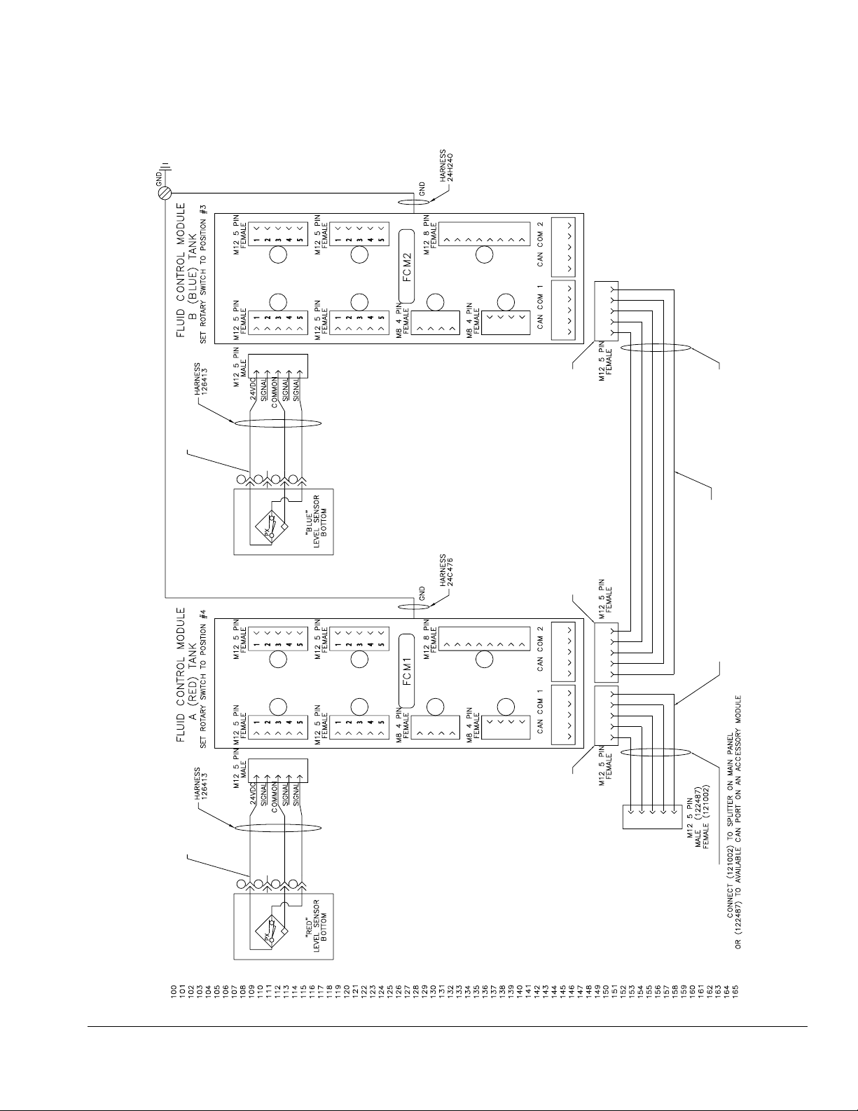
Electrical Schematics
GND
432
1
FEMALE
M12 5 PIN
5
1
FEMALE
M12 5 PIN
7
6
Electrical Schematics
24H24O
HARNESS
GND
54321
432
5
FEMALE
M12 8 PIN
876
5
1
B (BLUE) TANK
FEMALE
M12 5 PIN
SET ROTARY SWITCH TO POSITION #3
FLUID CONTROL MODULE
54321
54321
MALE
M12 5 PIN
HARNESS
126413
LABEL FCM2B
BOTH ENDS
A (RED) TANK
SET ROTARY SWITCH TO POSITION #4
FLUID CONTROL MODULE
HARNESS
126413
LABEL FCM1A
BOTH ENDS
24VDC
SIGNAL
1
2
1
FEMALE
M12 5 PIN
FEMALE
M12 5 PIN
MALE
M12 5 PIN
24VDC
SIGNAL
COMMON
3
PX___
7
1
COMMON
SIGNAL
SIGNAL
4
432
SIGNAL
SIGNAL
"BLUE"
5
54321
54321
FEMALE
M12 5 PIN
BOTTOM
LEVEL SENSOR
1
FEMALE
M12 5 PIN
FEMALE
M12 5 PIN
43215 43215
CAN COM 1 CAN COM 2
432
CAN COM 1
CAN COM 2
876
123451234512345
FEMALE
M12 5 PIN
FEMALE
M12 5 PIN
121597
HARNESS
BOTH ENDS
LABEL CAN1
LABEL CAN2
(2 CABLES)
1
FEMALE
M8 4 PIN
GND
3
432
24C476
HARNESS
FEMALE
M12 8 PIN
1
FEMALE
M8 4 PIN
54321
5
4
2
54321
432
5
6
FCM1 FCM2
43215 43215
CAN COM 1 CAN COM 2
432
CAN COM 1
FEMALE
M12 5 PIN
432
1
5
M12 5 PIN
MALE (122487)
FEMALE (121002)
1
FEMALE
M8 4 PIN
3
432
1
FEMALE
M8 4 PIN
4
2
54321
1
2
3
ti16632b
100
101
102
103
104
105
106
107
108
109
110
PX___
111
112
113
4
114
"RED"
BOTTOM
LEVEL SENSOR
118
116
115
117
119
120
121
122
123
124
125
126
127
128
129
130
131
132
133
134
135
136
137
138
139
140
141
142
143
144
145
146
147
148
149
150
151
152
153
154
155
156
157
158
159
HARNESS
CONNECT (121002) TO SPLITTER ON MAIN PANEL
122487 OR 121002
OR (122487) TO AVAILABLE CAN PORT ON AN ACCESSORY MODULE
162
160
161
165
163
164
FIG. 10: Drum Feed Kit 24N813
3A2806C 21
Page 22

Parts
Parts
Drum Feed System, 24N816
003
006
005
004
001
005
22 3A2806C
Page 23

Ref Part Description Quantity
001 24N804 PANEL, assy, fluid control, HFRL
(Inside Enclosure - Refer to F
IG. 2,
1
page 5)
003 255468 KIT, acc., light tower, TC ram 1
004 124003 CABLE, CAN, male-female, 5.0m 1
005* 24N767 KIT, drum feed, carbon (Optional) 1
006* 01/0955/25 RACK, 4 drum (Optional) 1
* Items are optional. Shown for clarity.
Replacement Danger and Warning labels, tags, and
cards are available at no cost.
Parts
3A2806C 23
Page 24

Parts
Drum Feed Kit, 24N767
100
121
116
117
118
119
118
115
102
103
101
102
104
105,
130
106
128
124
124
128
106
112
108
111
122
125
108
109
125
110
120
129,
130
126
107
114
115
127
r_24n767_parts
127
123
24 3A2806C
Page 25

Ref Part Description Quantity
101 109505 BUSHING 1
102 108209 NIPPLE, pipe close 2
103 94/0906-R2/99 VALVE, ball, 2w, 1-1/2npt, f, 1500ps 1
104 121443 FITTING, tee, 1 1/2npt 1
105 94/1045-M/99 BUSHING, 1.5nptx3/4npt, mf, ms, prox 1
106 94/0910/98 FITTING, barb, 1-1/2x1-1/2npt, m, ss 2
107 647673 PUMP, 1050a, ss/ss/pt/a 1
108 94/0398/99 FITTING, elbw, strt, 90, 1npt, mf, ms, 2 2
109 160022 FITTING, union, adapter 1
110 94/0758/99 FITTING, npl, hex, 1"x3/4npt, mm, ms, 2k 1
111 94/0433/99 FITTING, nipple, hex, 1npt, mm, 4.5k 1
112 123250 FITTING, coupling, 1.5nptx1npt, cs 1
114 123890 FITTING, tee, 1nptx1nptx1nptf, fff, c 1
115 94/0909/99 FITTING, nipple, barb, 1"x1"npt, m, ms 2
116 94/0459/99 BUSHING, 2nptx1npt, mf, blk, 150# 1
117 94/0456/99 FITTING, nipple, 1npt, mm, blk, sch40 1
118 94/0904-R2/99 VALVE, bal, 2w, 1''npt, f, 2000psi, ms 2
119 94/0912/99 FITTING, qd, 1''npt, m, cam, dfk, ms 1
120 94/0915/99 FITTING, qd, 1''npt, f, cam, dfk, ms 1
121 247616 DRYER, desiccant, option 1
122 94/0550/99 SWIVEL, 3/4npsx1npt, fm, ms, 4k 1
123 61/0055/88 HOSE, hose, chem, pe, 1", 200psi 6
124 61/0056/88 HOSE, chem, pe, 1-1/2 6
125 217382 HOSE, coupled, 10 ft 1
126 104969 BUSHING, reducing 1
127 94/0451-2/99 CLAMP, hose, 1-3/4"-3/4", ms 4
128 94/0414/99 CLAMP, hose, 2-1/4"-1-5/16", ms 4
129 94/0397-M/99 BUSHING, 1nptx3/4npt, mf, ms, prox 1
130* 102726 PLUG, pipe headles 2
Parts
Replacement Danger and Warning labels, tags, and
cards are available at no cost.
* Either the upper or lower plug can be removed and
replaced with a level sensor assembly.
- Only one sensor per chemical side can be used
- Both material sides should utilize the same (upper
or lower) sensor position.
3A2806C 25
Page 26

Parts
Electric Panel, 24N804
210
211
212
204
212
202
201
224
or
225
213
214
219
220
211
212
215
203
215
204
204,
215
205
206
208,
209
26 3A2806C
220
208,
209
207
233,
234
r_24n804_parts1
Page 27

222
221
Parts
223
220
218
214
225
224
213
216
217
r_24n804_parts2
3A2806C 27
Page 28

Parts
Ref Part Description Quantity
201 15Y917 PANEL, electric, heat 1
202 115942 NUT, hex, flange head 3
203 289697 MODULE, GCA, cube, base 2
204 24C476 HARNESS, wire, ground, term 1
205 102063 WASHER, lock, ext 2
206 114993 SCREW, mach, pan wash hd 2
207 102598 SCREW, cap, socket head 8
208 289696 MODULE, GCA, cube, FCM 2
209 277674 ENCLOSURE, cube door 2
210 100021 SCREW, cap hex hd 1
211 100015 NUT, hex mscr 2
212 100028 WASHER, lock 3
213 123452 HOLDER, anchor, wire tie, nylon 3
214 116610 SCREW, mach, phil, pan, #10 3
215 24H240 HARNESS, wire, ground, term, 9" 1
216 100020 WASHER, lock 1
217 100166 NUT, full hex 1
218 123679 BUSHING, wire protector, 1 3/8 od 1
219 121597 CABLE, CAN, 90 female/90 female 1
220 126413 HARNESS, m12xm12, 5px4p, mxf, 10m 2
221 121511 SENSOR, capacitive, 18mm, qck disc 2
222 16A511 HOUSING, well, prox, efector 2
223 15U978 CAP, well, prox, PR70 2
224 121002 CABLE, CAN, female / female 1.5m 1
225 122487 CABLE, CAN, male-female, 1.5m 1
226 16D656 LABEL, identification, electronics 1
227 070408 SEALANT, pipe, sst 1
228 16H821 TOKEN, GCA, upgrade, ADM32 1
229 16E530 SOFTWARE, GCA, tank stand 1
230 24N813 CONTROL, panel, HFRL, low levels 1
233 15A721 LABEL, designation 1
Replacement Danger and Warning labels, tags, and
cards are available at no cost.
28 3A2806C
Page 29

Parts
3A2806C 29
Page 30

Parts
4 Drum Rack, 01/0955/25
(Optional)
(Typical Installation - 9 Places)
305
305
305
303
301
304
305
305
A
F
302
D
C
305
E
B
Rack Dimensions:
A (Height): 60-1/2 in. (154 cm)
B (Length): 36-1/2 in. (93 cm)
C (Width): 60-1/2 in. (154 cm)
Anchor Locations:
D (Width): 57-1/2 in. (146 cm)
E (Length): 33-1/2 in. (85 cm)
F (Diameter): Ø 0.56 in. (1.4 cm)
30 3A2806C
To avoid machine damage or personal injury,
anchor the rack to the floor with (4) 1/2” bolts (provided by customer) and verify all bolt assemblies
are tightened before loading the drums onto the
rack.
01_0955_25
NOTICE
Page 31

Ref Part Description Quantity
301 01/0955-A/99 SHELF, rack, 4 drum 2
302 01/0955-B/99 SUPPORT, shelf, rack, 2/4 drum, right 1
303 01/0955-C/99 SUPPORT, shelf, rack, 2/4 drum, left 1
304 01/0955-D/99 STRAP, stabilizer, rack, 4 drum 2
305 01/0955/50 RACK, 2/4 drum, seal, hardware 1
Parts
3A2806C 31
Page 32

Appendix A - ADM Setup Screens Overview
Appendix A - ADM Setup Screens Overview
For other screen not mentioned, refer to the HFRL and
HFRS, Setup-Operations manual.
Supply Screen
This screen allows the user to specify the operating
parameters for off-board, integrated tanks and indicate
which positions have level sensors installed.
Activate at least 2 level sensors for each reservoir or the
level sensor functions will be disabled.
For a single low sensor in each drum feed, configure as
shown below. (Activate mid and low sensors, and set
refill setting to monitor).
Advanced Screen 1
This screen allows the user to set the language, date
format, current date, time, setup screens password,
screen saver delay, and turn on or off silent mode.
• Time: formatted in 24 hour time.
• Password: Enables the setup screens to be pass-
word protected. Entering “0000” disables the feature.
• Screen Saver: Enter the amount of time until the
backlight turns off. Entering “0” leave it constantly
on.
• Silent Mode: Check this box to turn off the buzzer
for key presses.
Advanced Screen 2
This screen allows the user to set the units of measure.
32 3A2806C
Page 33

Appendix A - ADM Setup Screens Overview
Advanced Screen 3
This screen allows the user to control the availability of
some key system features.
• Disable Dispensing From Display: Check this box
to disable dispensing from the ADM. A footswitch,
dispense valve trigger, or other external signal will
be the only way to initiate a dispense.
• Disable Modifying Temp Setpoint: Check this box
to disable modifying temperature setpoints from the
Run screens. This is only applicable if temperature
control items are installed and enabled.
• Disable Operator Mode Adjustments: When this
box is checked, the user will not be able to adjust
the dispense settings in Operator Mode.
• Dispense from Home Position: When this box is
checked, the machine will be required to reach a
defined home position before dispensing in shot or
sequence mode.
Advanced Screen 4
This screen is for enabling the optional ADM screens,
enabling USB log downloading, and erasing USB logs.
To enable the machine to automatically stop dispensing
when a reservoir is low: place an “X” beside the “Low
Material Disables Dispense” check box. When this feature is active, the machine will not cycle unless material
is present in the monitored reservoirs.
• Temperature Alarm Disables Dispense: When
this box is checked, the system will reject dispense
requests when any enabled heat/chiller zones are
below/above their setpoint.
• Enable Operator Mode Cavitation Alarm: Check
this box to enable cavitation alarms in Operator
Mode. Clear this box to disable cavitation alarms in
Operator Mode.
• Complete Dispense with Setpoint Error: When
this box is checked, the shot will continue dispensing even if the system never reaches the desired
setpoint.
• Enable Shot Aborted Notification: When this box
is checked, a pop-up notification will be displayed
when a shot is aborted.
• 2x Trigger For Dispense: When this box is
checked, the machine will require a double trigger
pull to initiate dispensing in shot or sequence mode.
3A2806C 33
Page 34

Appendix A - ADM Setup Screens Overview
Advanced Screen 5
This screen displays software information.
If the level controls are present but not active, the tank
monitor program will not appear in the advanced 5
screen as shown below.
34 3A2806C
Page 35

Appendix B - ADM Run Screens Overview
Appendix B - ADM Run Screens Overview
For other screen not mentioned, refer to the HFRL and
HFRS, Setup-Operations manual.
Home Screen, Refill Disabled
If refill is Disabled, the home screen will not show a
graphic display of the reservoirs.
Home Screen, Refill Enabled
Home Screen, Low Level - A (Red) Side
When a low level on the RED side is sensed, the pop up
error code appears and the active error display reads
“Red Low Material Level”. The light stack will flash yellow, and the audible alarm will sound. When this error
occurs, the machine will continue to dispense when a
start is initiated, unless the “Low Material Disables Dispense” flag is set.
Refer to Advanced Screen 3 to configure the machine
to stop dispensing when a low level sensor is triggered.
When the level sensors are active and both reservoirs
have material, the display looks as above. The stack
light will illuminate a solid green (Unless another error is
present).
When the level condition is acknowledged by the operator (by hitting the enter key), but not cleared; the audible
alarm will stop, and the pop up window will disappear.
The active error display will still indicate a low level condition, and the stack light will continue to flash yellow,
unless the low level condition has been corrected.
3A2806C 35
Page 36

Appendix B - ADM Run Screens Overview
Home Screen, Low Level - B (Blue) Side
When a low level on the BLUE side is sensed, the pop
up error code appears and the active error display reads
“Red Low Material Level”. The light stack will flash yellow, and the audible alarm will sound. When this error
occurs, the machine will continue to dispense when a
start is initiated, unless the “Low Material Disables Dispense” flag is set.
Refer to Advanced Screen 3 to configure the machine
to stop dispensing when a low level sensor is triggered.
When the level condition is acknowledged by the operator (by hitting the enter key), but not cleared; the audible
alarm will stop, and the pop up window will disappear.
The active error display will still indicate a low level condition, and the stack light will continue to flash yellow,
unless the low level condition has been corrected.
36 3A2806C
Page 37

Technical Data
Technical Data
Level Detection Module and Drum Feed Kit
US Metric
Maximum fluid working pressure 125 psi 0.86 MPa, 8.6 bar
Maximum air input pressure 125 psi 0.86 MPa, 8.6 bar
Noise (dBa)
Maximum sound pressure
Maximum sound power
Inlet/Outlet Sizes
Air inlet size
Materials of Construction
Wetted materials Carbon steel, PTFE, Stainless Steel, PE, Aluminum, Nylon
Weight
24N816 16 lb 7.3 kg
24N767 (Optional) 69 lb 31 kg
01/0955/25 (Optional) 209 lb 95 kg
Notes
† For additional technical data regarding the HFRL and HFRS systems, refer to manual.
For additional technical data regarding the Husky 1050 Air-Operated Diaphragm Pump, refer to manual.
†
†
1/2 NPTF
3A2806C 37
Page 38

Graco Standard Warranty
Graco warrants all equipment referenced in this document which is manufactured by Graco and bearing its name to be free from defects in
material and workmanship on the date of sale to the original purchaser for use. With the exception of any special, extended, or limited warranty
published by Graco, Graco will, for a period of twelve months from the date of sale, repair or replace any part of the equipment determined by
Graco to be defective. This warranty applies only when the equipment is installed, operated and maintained in accordance with Graco’s written
recommendations.
This warranty does not cover, and Graco shall not be liable for general wear and tear, or any malfunction, damage or wear caused by faulty
installation, misapplication, abrasion, corrosion, inadequate or improper maintenance, negligence, accident, tampering, or substitution of
non-Graco component parts. Nor shall Graco be liable for malfunction, damage or wear caused by the incompatibility of Graco equipment with
structures, accessories, equipment or materials not supplied by Graco, or the improper design, manufacture, installation, operation or
maintenance of structures, accessories, equipment or materials not supplied by Graco.
This warranty is conditioned upon the prepaid return of the equipment claimed to be defective to an authorized Graco distributor for verification of
the claimed defect. If the claimed defect is verified, Graco will repair or replace free of charge any defective parts. The equipment will be returned
to the original purchaser transportation prepaid. If inspection of the equipment does not disclose any defect in material or workmanship, repairs will
be made at a reasonable charge, which charges may include the costs of parts, labor, and transportation.
THIS WARRANTY IS EXCLUSIVE, AND IS IN LIEU OF ANY OTHER WARRANTIES, EXPRESS OR IMPLIED, INCLUDING BUT NOT LIMITED
TO WARRANTY OF MERCHANTABILITY OR WARRANTY OF FITNESS FOR A PARTICULAR PURPOSE.
Graco’s sole obligation and buyer’s sole remedy for any breach of warranty shall be as set forth above. The buyer agrees that no other remedy
(including, but not limited to, incidental or consequential damages for lost profits, lost sales, injury to person or property, or any other incidental or
consequential loss) shall be available. Any action for breach of warranty must be brought within two (2) years of the date of sale.
GRACO MAKES NO WARRANTY, AND DISCLAIMS ALL IMPLIED WARRANTIES OF MERCHANTABILITY AND FITNESS FOR A
PARTICULAR PURPOSE, IN CONNECTION WITH ACCESSORIES, EQUIPMENT, MATERIALS OR COMPONENTS SOLD BUT NOT
MANUFACTURED BY GRACO. These items sold, but not manufactured by Graco (such as electric motors, switches, hose, etc.), are subject to
the warranty, if any, of their manufacturer. Graco will provide purchaser with reasonable assistance in making any claim for breach of these
warranties.
In no event will Graco be liable for indirect, incidental, special or consequential damages resulting from Graco supplying equipment hereunder, or
the furnishing, performance, or use of any products or other goods sold hereto, whether due to a breach of contract, breach of warranty, the
negligence of Graco, or otherwise.
FOR GRACO CANADA CUSTOMERS
The Parties acknowledge that they have required that the present document, as well as all documents, notices and legal proceedings entered into,
given or instituted pursuant hereto or relating directly or indirectly hereto, be drawn up in English. Les parties reconnaissent avoir convenu que la
rédaction du présente document sera en Anglais, ainsi que tous documents, avis et procédures judiciaires exécutés, donnés ou intentés, à la suite
de ou en rapport, directement ou indirectement, avec les procédures concernées.
Graco Information
For the latest information about Graco products, visit www.graco.com.
TO PLACE AN ORDER, contact your Graco distributor or call to identify the nearest distributor.
Phone: 612-623-6921 or Toll Free: 1-800-746-1334 Fax: 330-966-3006
All written and visual data contained in this document reflects the latest product information available at the time of publication.
GRACO INC. AND SUBSIDIARIES • P.O. BOX 1441 • MINNEAPOLIS MN 55440-1441 • USA
Copyright 2012, Graco Inc. All Graco manufacturing locations are registered to ISO 9001.
Graco reserves the right to make changes at any time without notice.
For patent information, see www.graco.com/patents.
Original Instructions. This manual contains English. MM 3A2806
Graco Headquarters: Minneapolis
International Offices: Belgium, China, Japan, Korea
www.graco.com
Revised November 2013
 Loading...