

Page 1
Repair-Parts
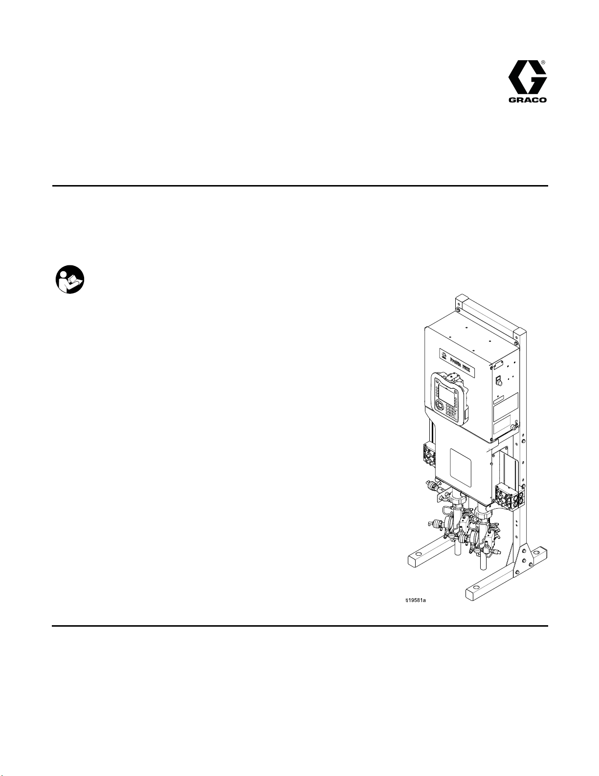
ProMix® PD2K Electronic
Proportioner
Positive displacement proportioning of 2-component materials helps reduce waste. Manual system with
Advanced Display Module. For professional use only.
Important Safety Instructions
Read all warnings and instructions in this manual.
Save these instructions.
Seepage3
approval
for model part numbers and
s information.
3A2800B
EN
PROVEN QUALITY. LEADING TECHNOLOGY.
Page 2

Contents
Models............................................................... 3
Related Manuals ................................................ 5
Warnings ........................................................... 6
Important Is
Troubleshooting.................................................. 11
System Troubleshooting............................... 11
Error Code Troubleshooting.......................... 12
Booth Control Troubleshooting...................... 22
Power Barrier Board Troubleshooting............ 23
Isolation Board Troubleshooting.................... 24
Enhanced Fluid Control Module
Pump Module Troubleshooting ..................... 26
Advanced Display Module
Notes ................................................................ 28
ocyanate (ISO) Information ................ 9
Troubleshooting.............................. 25
Troubleshooting.............................. 27
Electrical Sc
Optional Cabl
Repair................................................................ 36
Before Servicing .......................................... 36
Pressure Relief Procedure............................ 37
Repairing the Advanced Display Module
Servicing the Control Box ............................. 39
Servicing the Fluid Section ........................... 48
Parts.................................................................. 52
Proportioner Parts........................................ 52
Control Box Parts......................................... 55
Solenoid Manifold Parts................................ 58
Technical
Graco Standard Warranty.................................... 60
hematics.......................................... 29
es and Modules ....................... 35
(ADM) ............................................ 38
Data ................................................... 59
2
3A2800B
Page 3
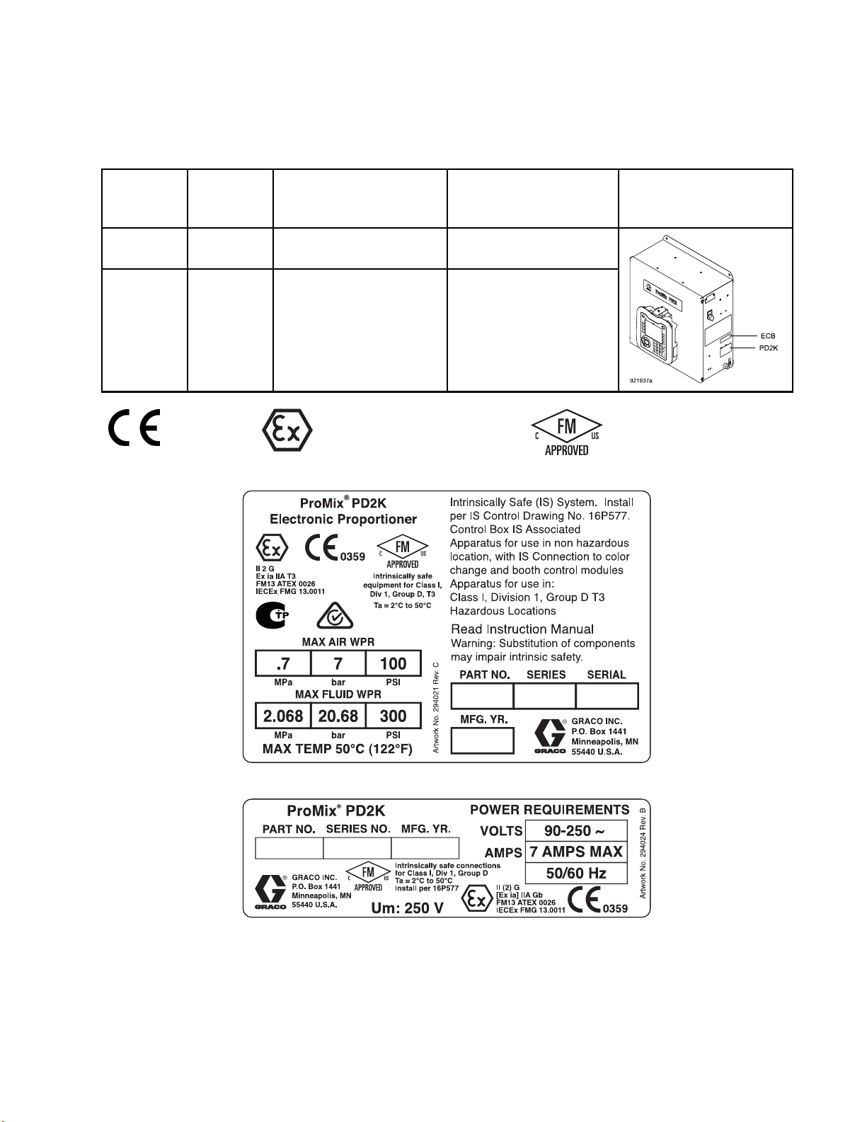
Models
See Figs. 1–7 for component identification labels, including approval information and certification.
Models
Part No.
MC1000
MC2000
0359
Series
A
A
Maximum Air Working
Pressure
100 psi (0.7 MPa, 7.0 bar) 300 psi (2.068 MPa,
100 psi (0.7 MPa, 7.0 bar) 1500 psi (10.34 MPa,
II 2 G
Maximum Fluid Working
Pressure
20.68 bar)
103.4 bar)
Location of PD
Electrical Co
(ECB) Labels
ntrol Box
2K and
Figure 1 Model MC1000 (Low Pressure) Identification Label
Figure 2 24M672 Control Box Identification Label
Continued on the next page.
3A2800B 3
Page 4
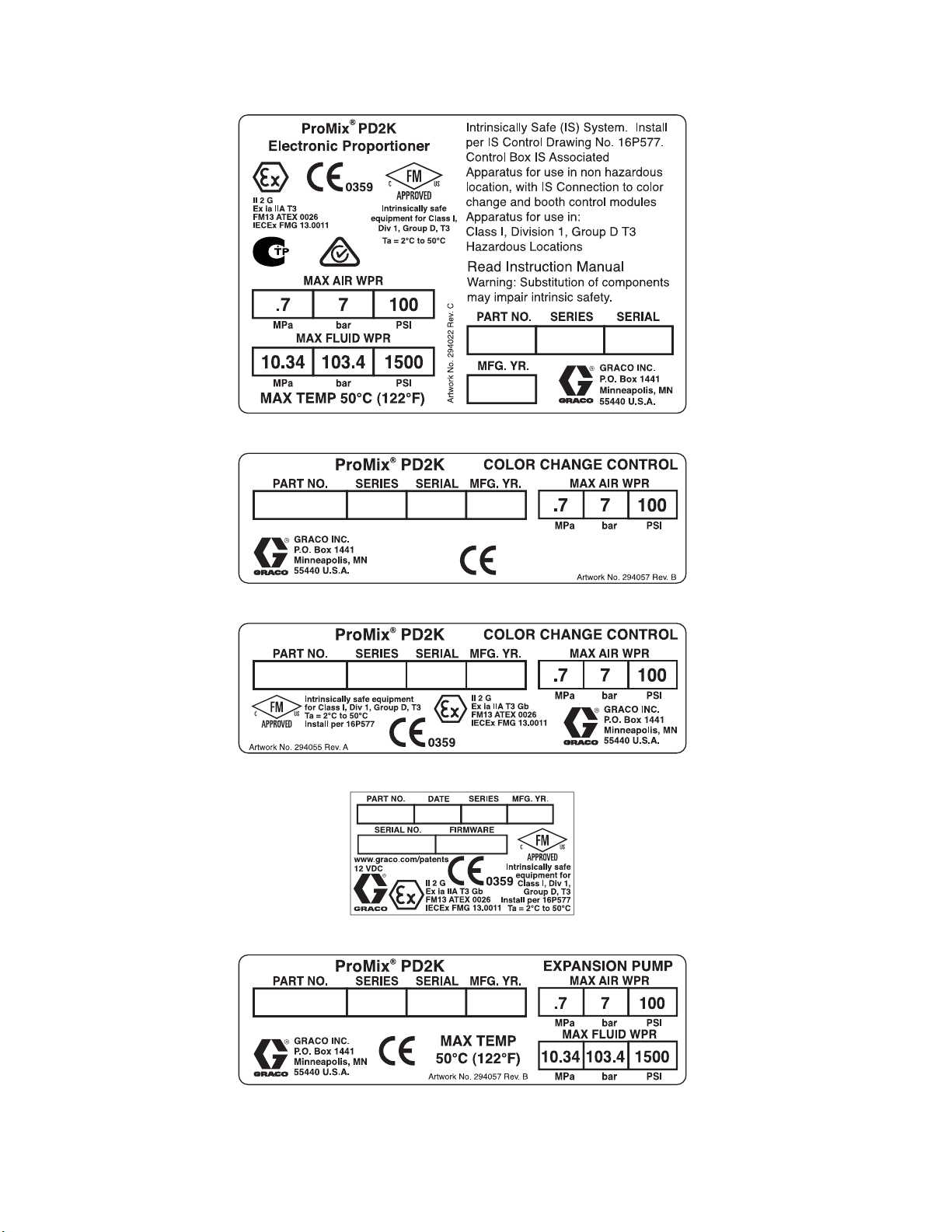
Models
Figure 3 Model MC2000 (High Pressure) Identification Label
Figure 4 Non-Intrinsically Safe Color Change Control (Accessory) Identification Label
Figure 5 Intrinsically Safe Color Change Control (Accessory) Identification Label
Figure 6 Booth Control Identification Label
Figure 7 Pump Expansion Kit (Accessory) Identification Label
4
3A2800B
Page 5
Related Manuals
Related Manuals
Manual No. Description
332457 PD2K Proportioner Installation
Manual, Manual Systems
332562
3A2801 Mix Module Instructions-Parts
332339 Pump Repair
PD2K Proportioner Operation
Manual, Manual Systems
Manual
-Parts Manual
Manual No. Description
332454
332455
332456 3rd and 4th P
Color Change V
Manual
Color Change Kits
Instructions-Parts Manual
Instructio
ns-Parts Manual
alve Repair-Parts
ump Kits
3A2800B 5
Page 6
Warnings
Warnings
The following
exclamation p
risks. When th
Warnings. Pr
the body of th
warnings are for the setup, use, grounding, maintenance and repair of this equipment. The
oint symbol alerts you to a general warning and the hazard symbol refers to procedure-specific
ese symbols appear in the body of this manual or on warning labels, refer backtothese
oduct-specific hazard symbols and warnings not covered in this section may appear throughout
is manual where applicable.
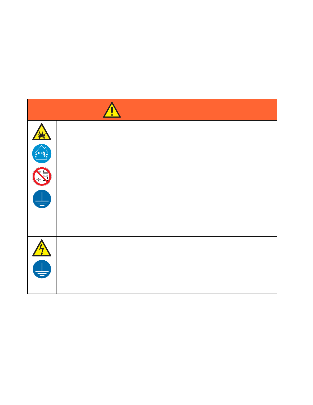
WARNING
FIRE AND EXPLOSION HAZARD
Flammable
prevent fir
• Use equipment only in well ventilated area.
• Eliminat
plastic d
• Keep work area free of debris, including solvent, rags and gasoline.
• Do not plug or unplug power cords, or turn power or light switches on or off when flammable
fumes are present.
•Grounda
• Use only grounded hoses.
• Hold gun firmly to side of grounded pail when triggering into pail. Do not use pail liners unless
they are antistatic or conductive.
• Stop op
equipm
• Keep a working fire extinguisher in the work area.
fumes, such as solvent and paint fumes, in work area can ignite or explode. To help
e and explosion:
e all ignition sources; such as pilot lights, cigarettes, portable electric lamps, and
rop cloths (potential static arc).
ll equipment in the work area. See Grounding instructions.
eration immediately if static sparking occurs or you feel a shock, Do not use
ent until you identify and correct the problem.
ELECTRIC SHOCK HAZARD
This equipment must be grounded. Improper grounding, setup, or usage of the system can
cause electric shock.
• Turn off and disconnect power at main switch before disconnecting any cables and before
servicing or installing equipment.
• Connect only to grounded power source.
lectrical wiring must be done by a qualified electrician and comply with all local codes
•Alle
egulations.
and r
6 3A2800B
Page 7
Warnings
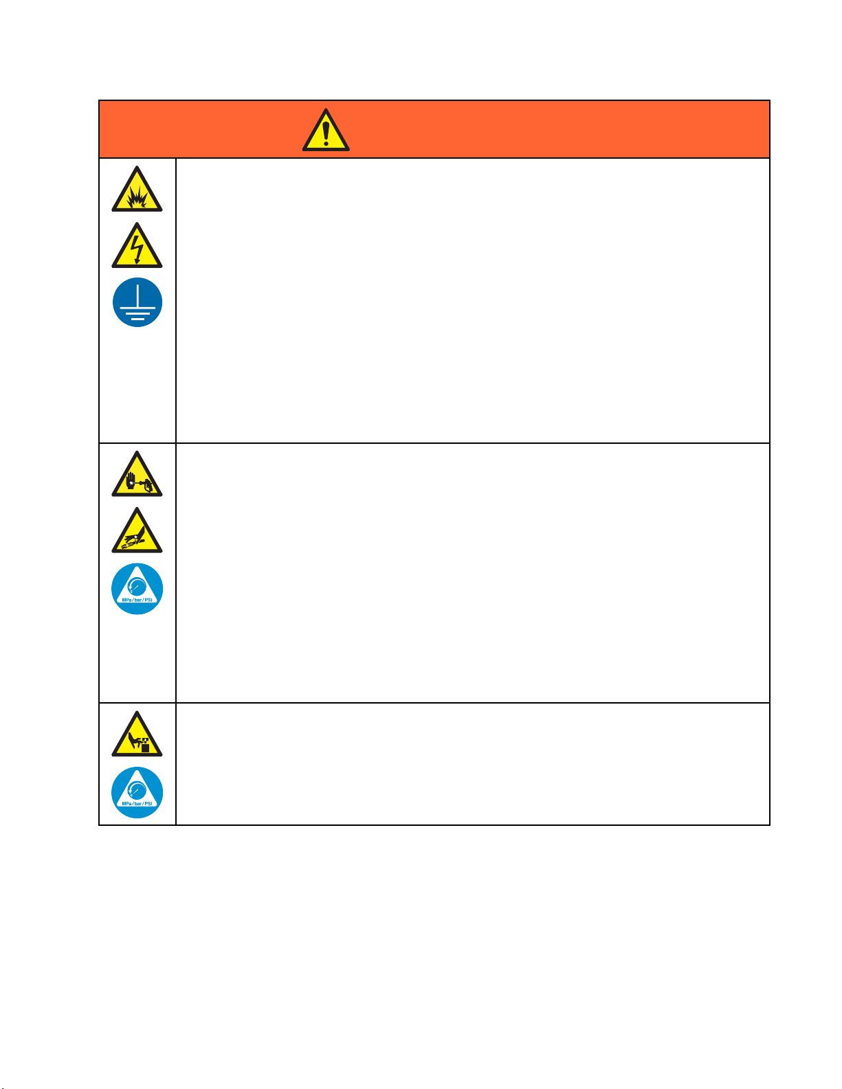
WARNING
INTRINSIC SAFETY
Intrinsically safe equipment that is installed improperly or connected to non-intrinsically safe
equipment will create a hazardous condition and can cause fire, explosion, or electric shock.
Follow local regulations and the following safety requirements.
•Besureyouri
electrical a
and 2 (Europ
NFPA 33, NEC
• To help prevent fire and explosion:
• Do not install equipment approved only for a non-hazardous location in a hazardous
location. See model ID label for the intrinsic safety rating of your model.
• Do not subs
• Equipment that comes in contact with the intrinsically safe terminals must be rated for Intrinsic
Safety. This includes DC voltage meters, ohmmeters, cables, and connections. Remove the
unit from the hazardous area when troubleshooting.
SKIN INJECTION HAZARD
High-pressure fluid from gun, hose leaks, or ruptured components will pierce skin. This may
look like just a cut, but it is a serious injury that can result in amputation. Get immediate surgical
treatment.
• Do not sp
• Engage trigger lock when not spraying.
• Do not point gun at anyone or at any part of the body.
•Donotp
• Do not stop or deflect leaks with your hand, body, glove, or rag.
• Follow the Pressure Relief Procedure when you stop spraying/dispensing and before
cleaning, checking, or servicing equipment.
•Tight
• Check hoses and couplings daily. Replace worn or damaged parts immediately.
en all fluid connections before operating the equipment.
nstallation complies with national, state, and local codes for the installation of
pparatus in a Class I, Group D, Division 1 (North America) or Class I, Zones 1
e) Hazardous Location, including all of the local safety fire codes (for example,
500 and 516, OSHA 1910.107, etc.).
titute system components as this may impair intrinsic safety.
ray without tip guard and trigger guard installed.
ut your hand over the spray tip.
3A2800B
MOVING PARTS HAZARD
Moving parts can pinch, cut or amputate fingers and other body parts.
• Keep clear of moving parts.
• Do not operate equipment with protective guards or covers removed.
ssurized equipment can start without warning. Before checking, moving, or servicing
•Pre
ipment, follow the Pressure Relief Procedure and disconnect all power sources.
equ
7
Page 8
Warnings
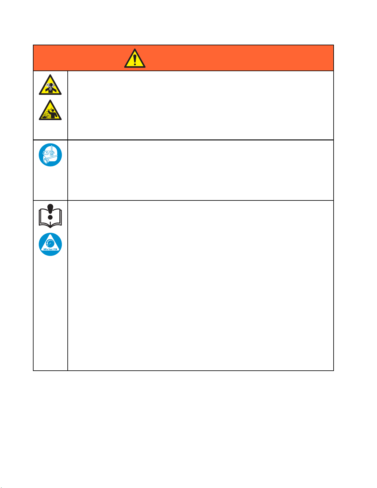
WARNING
TOXIC FLUID OR FUMES
Toxic fluids or fumes can cause serious injury or death if splashed in the eyesoronskin,
inhaled, or swallowed.
• Read MSDSs to know the specific hazards of the fluids you are using.
• Store hazardous fluid in approved containers, and dispose of it according to applicable
guidelines.
• Always wear
equipment.
PERSONAL PROTECTIVE EQUIPMENT
Wear appropriate protective equipment when in the work area to help prevent serious injury,
including eye injury, hearing loss, inhalation of toxic fumes, and burns. This protective
equipment includes but is not limited to:
chemically impermeable gloves when spraying, dispensing, or cleaning
•Protectiv
• Respirators, protective clothing, and gloves as recommended by the fluid and solvent
manufacturer.
EQUIPMENT MISUSE HAZARD
Misuse can cause death or serious injury.
• Do not operate the unit when fatigued or under the influence of drugs or alcohol.
• Do not exceed the maximum working pressure or temperature rating of the lowest rated
system component. See Technical Data in all equipment manuals.
•Useflui
in all e
inform
• Do not leave the work area while equipment is energized or under pressure.
• Turn off all equipment and follow the Pressure Relief Procedure when equipment is not in use.
•Check
manuf
• Do not alter or modify equipment. Alterations or modifications may void agency approvals
and create safety hazards.
• Make sure all equipment is rated and approved for the environment in which youareusingit.
•Usee
• Route hoses and cables away from traffic areas, sharp edges, moving parts, and hot surfaces.
• Do not kink or over bend hoses or use hoses to pull equipment.
•Kee
• Comply with all applicable safety regulations.
e eyewear, and hearing protection.
ds and solvents that are compatible with equipment wetted parts. See Technical Data
quipment manuals. Read fluid and solvent manufacturer’s warnings. For complete
ation about your material, request MSDS from distributor or retailer.
equipment daily. Repair or replace worn or damaged parts immediately with genuine
acturer’s replacement parts only.
quipment only for its intended purpose. Call your distributor for information.
p children and animals away from work area.
8 3A2800B
Page 9
Important Isocy
anate (ISO) Information
Important Iso
Isocyanates (ISO) are catalysts used in two
component materials.
cyanate (ISO) Information
Isocyanate Conditions
Spraying or dispensing materials containing
isocyanates creates potentially harmful mists,
vapors, and atomized particulates.
Read material manufacturer’s warnings and
material MSDS to know specific hazards and
precautions related to isocyanates.
Prevent inhalation of isocyanate mists, vapors,
and atomized particulates by providing sufficient
ventilation in the work area. If sufficient ventilation
is not available, a supplied-air respirator is required
for everyone in the work area.
To prevent contact with isocyanates, appropriate
personal protective equipment, including
chemically impermeable gloves, boots, aprons,
and goggles, is also required for everyone in the
work area.
Keep Components A and B Separate
Cross-contamination can result in cured
material in fluid lines which could cause serious
injury or damage equipment. To prevent
cross-contamination:
• Never interchange component A and component
B wetted parts.
• Never use solvent on one side if it has been
contaminated from the other side.
Moisture Sensitivity of Isocyanates
Exposure to moisture (such as humidity) will cause
ISO to partially cure; forming small, hard, abrasive
crystals, which become suspended in the fluid.
Eventually a film will form on the surface and the ISO
will begin to gel, increasing in viscosity.
NOTICE
Partially cured ISO will reduce performance and
the life of all wetted parts.
• Always use a sealed container with a desiccant
Material Self-ignition
Some materials may become self-igniting if applied
too thick. Read material manufacturer’s warnings
and material MSDS.
3A2800B 9
dryer in the vent, or a nitrogen atmosphere.
Never store ISO in an open container.
• Keep the ISO pump wet cup or reservoir (if
installed) filled with appropriate lubricant. The
lubricant creates a barrier between the ISO and
the atmosphere.
• Use only moisture-proof hoses compatible with
ISO.
• Never use reclaimed solvents, which may
contain moisture. Always keep solvent
containers closed when not in use.
• Always lubricate threaded parts with an
appropriate lubricant when reassembling.
NOTE: The amount of film formation and rate of
crystallization varies depending on the blend of ISO,
the humidity, and the temperature.
Page 10

Important Isocy
anate (ISO) Information
Changing Mate
rials
NOTICE
Changing the material types used in your
equipment requires special attention to avoid
equipment damage and downtime.
• When changi
multiple ti
• Always clea
flushing.
•Checkwith
chemical c
• When chang
or polyur
componen
have amin
often hav
ng materials, flush the equipment
mes to ensure it is thoroughly clean.
n the fluid inlet strainers after
your material manufacturer for
ompatibility.
ing between epoxies and urethanes
eas, disassemble and clean all fluid
ts and change hoses. Epoxies often
es on the B (hardener) side. Polyureas
eaminesontheA(resin)side.
10 3A2800B
Page 11
Troubleshooting
NOTE: Check all possible remedies before disassembling the system.
System Troubleshooting
Troubleshootin
g
Problem
Unit will not operate.
Pump output low on both strokes.
p output low on only one
Pum
roke.
st
No output. Improperly installed dosing valves.
Cause Solution
Inadequate power supply.
Power switch is off.
Main power is shut off.
Exhaust
Clogged fluid outlet line, valves,
etc.
Fluid d
Inadequate power supply.
Exhausted fluid supply. Refill and reprime pump.
Clog
etc.
Worn piston packings.
Hel
Worn piston packing.
ed fluid supply.
ried on piston rod.
ged fluid outlet line, valves,
d open or worn dosing valves.
See Techni
Turn switch on.
Turn main
Refill an
Clear.
Disass
See pum
pump at
See Technical Data, page 59.
r.
Clea
Replace. See pump manual.
Check and repair. See valve
manual.
place. See pump manual.
Re
Check solenoid connections to
valves. See pump manual.
cal Data, page 59.
power switch on.
d reprime pump.
emble and clean pump.
p manual. In future, stop
bottom of stroke.
ump operates erratically.
P
3A2800B
Exhausted fluid supply. Refill and reprime pump.
Held open or worn dosing valves.
Worn piston packing.
Check and repair. See pump
manual.
Replace. See pump manual.
11
Page 12

Troubleshootin
g
Error Code Tro
System errors alert you of a problem and help
prevent off-ratio spraying. There are three types:
Advisory, Deviation, and Alarm.
An Advisory r
clear itself
A Deviation records an error in the system but does
not shut down the equipment. The deviation must be
acknowledged by the user.
If an Alarm occurs, operation stops.
If any of th
• Alarm buzzer sounds (unless in silent mode).
• Alarm popup screen shows the active alarm code.
• Status bar on the Advanced Display Module shows
theactivealarmcode.
• Alarm is saved in the date/time stamped log.
Code
B9A0 AdvisoryVolume
ecords an event in the system, and will
after 60 seconds.
e three types occur:
Type Description Problem
ubleshooting
Batch counter for
Rollove
Current
rA
material A rolled over.
NOTE: When an error occurs be sure to determine
the code before resetting it. If you forget which code
occurred, the Errors screen displays the 200 most
recent errors, with date, time, and description.
NOTE: In some
is shown as th
applicable
display wil
last digit i
Cause Solution
The tota
reached
capable
starte
error codes listed below, a # symbol
e last digit. This symbol represents the
pump number, which can vary. The unit’s
l show the applicable pump number as the
n the code.
lizer has
maximum
value and
d over at zero.
n/a
B9AX Advisory Volume
Rollover A
Lifetime
B9B0 Advisory Volume
Rollover B
Current
B9BX Advi
B9D#
Advisory Volume
sory
me
Volu
over B
Roll
time
Life
Rollover
Pump #
Grand total counter for
material A rolled over.
counter for
Batch
ial B rolled over.
mater
Grand total counter for
material B rolled over.
Grand total counter for
pump#rolledover.
The totalizer has
reached maximum
capable value and
started over at zero.
The totalizer has
reached maximum
capable value and
started over at zero.
otalizer has
The t
hed maximum
reac
ble value and
capa
ted over at zero.
star
The totalizer has
reached maximum
capable value and
started over at zero.
n/a
n/a
n/a
n/a
2
1
3A2800B
Page 13

Troubleshootin
g
Code
B9S0
B9SX
CAC#
CA0X
CADX
Type Description Problem
Advisory Volume
Rollover
Solvent
Current
Advisory Volume
Rollover
Solvent
Lifetime
Alarm
Alarm
Alarm
Comm.
Error Color
Change #
Comm.
Error ADM
Comm.
Error Fluid
Module
Batch counter
material S rol
Grand total counter for
material S rolled over.
System does not see
the Color Change
Module #.
System does not see
the Advanced Display
Module.
System does not
see the Enhanced
Fluid Control Module
(EFCM).
for
led over.
Cause Solution
The totalizer has
reached maximum
capable value and
started over at zero.
The totalize
reached maxi
capable valu
started over
This communication
error indicates that
the network has lost
communication with
the Color Change
Module #.
This comm
error ind
the Netwo
communic
the Adva
Module.
This communication
error indicates that
the Network has lost
communication with
the EFCM.
r has
mum
eand
at zero.
unication
icates that
rk has lost
ation with
nced Display
n/a
n/a
Check CAN cable
connections to
the Color Change
Module # and any
interconnected
modules.
Check CAN cable
connecting ADM to the
EFCM.
Check CAN cables
connecting ADM to
the EFCM. Replace
Cable or EFCM as
necessary.
CANX
CDC
Adviso
Alarm Duplicate
#
ry
Comm.
Error Booth
Control
Color
Change #
System does not see
the Booth Control (and
manual system).
tem sees two or
Sys
e identical Color
mor
nge Modules.
Cha
ommunication
This c
indicates that
error
twork has lost
the Ne
commu
the Bo
modu
Mor
Cha
con
sys
ad
nication with
oth Control
le.
e than one Color
nge Module is
nected in the
tem with the same
dress.
Check CAN cables
connecting booth
control to the Isolation
board. Check Isolation
board power. Replace
cable, booth control,
Isolation board or
Barrier board as
necessary.
ck the system and
Che
ove the extra color
rem
nge module.
cha
3A2800B 13
Page 14

Troubleshootin
g
Code
CDDX
CDNX
DA0#
DE0#
Type Description Problem
Alarm Duplicate
Fluid
Module
Alarm Duplicate
Booth
Control
Alarm Exceeded
Max Flow
Pump #
Alarm Leak Pump#This is a manual stall
System sees tw
more identica
Control Modul
System sees two or
more identical Booth
Control Modules.
Pump was driven to
its maximum allowed
speed.
test failure when the
pump cannot build
pressure to the target
“Stall Test Pressure.”
Will fault after 30
seconds.
oor
l Fluid
es.
Cause Solution
More than one Fluid
Control Module is
connected in the
system.
More than one
Control Modu
connected in
system.
System has a leak
or open valve that is
allowing unrestricted
flow.
Pump is cav
cycling wi
ion.
restrict
Viscosity of material is
too thin for nozzle size.
No material in the
pump or line.
Leak in
the system.
Booth
le is
the
itating,
thout
Check the syst
remove the ext
control modul
Check the system
and remove the extra
booth control module.
Inspect system for
leaks.
Verify pump is being
supplied material.
Reduce nozzle size
to create more
restriction. Reduce
paint pressure to lower
the flow rate.
Make sure the pump
and down stream color
line are loaded with
material.
Determine if leak is
external or internal
by visually inspecting
the system for fluid
leakage. Fix all loose
or worn hoses, fittings,
and seals. Inspect
all valve seats and
needles for wear, and
replace worn piston or
throat seals.
em and
ra fluid
e.
DF0
4
1
Alarm
#
No S
Pum
tall Up
p#
p stall test failed;
Pum
p did not stall on
pum
up stroke.
the
ve failure, seal
Val
lure, worn rod or
fai
inder.
cyl
Replace inlet and
outlet valve and
seal for up stroke.
Replace piston and
throat seals. Replace
rod and cylinder as
necessary.
3A2800B
Page 15

Troubleshootin
g
Code
DG0#
DH0#
DK0#
EAUX Advisory
Type Description Problem
Alarm
Alarm
Alarm Position
No Stall
Down
Pump #
No Stall
Pump #
Pump #
USB Busy USB driv
Pump stall tes
pump did not st
the down strok
Pump stall test failed;
pump did not stall on
either the up or down
stroke.
Thepumpwas
detected to be out
of position.
d, download is
inserte
in progr
t failed;
all on
e.
e has been
ess.
Cause Solution
Valve failure
failure, worn
cylinder.
Valve failure, seal
failure, worn rod or
cylinder.
Indicat
is uploa
downloa
,seal
rod or
es USB port
ding or
ding data.
Replace inlet and
outlet valve and seal
for down stroke.
Replace piston and
throat seals. Replace
rod and cylinder as
necessary.
Replace inle
outlet valv
for up and do
strokes. Re
piston and t
seals. Rep
rod and cyl
necessary
Re-enable pump
power to reset pump.
Wait for
t and
e and seal
wn
place
hroat
lace
inder as
.
USB Idle.
EB00 Record
EBH#
EBUX Record
EC00
0#
EF
Record Home
rd
Reco
Alarm Timeout
Stop
Button
Pressed
Comple
Pump #
USB
drive was
removed.
Setup
Value(s)
Changed
Startup
Pump #
te
Recordofastopbutton
press.
Record of pump
homing complete.
USB drive was
removed while
downloading or
uploading.
Record of changing
setup variables.
Pump tried but was not
able to move to the
home position within
a specified amount of
time.
Indicates system stop
key on ADM was
pressed.
An indi
displa
compl
funct
Downloading/uploading
data on USB was
interrupted by the USB
device being removed.
Indi
whe
wer
Pump dose valves did
not actuate.
Motor could not drive
pumps and linear
actuator.
Pump stroke length
is shortened by
mechanical system
tolerance.
cation on the
y that the pump
eted the home
ion
cates date and time
n setup values
e changed.
n/a
No acti
Replace the USB
device and begin
process again.
n/a
Ve
to
Ve
ac
Verify motor is driving
the pump.
V
assembly of linear
actuator and pump
piston rods. See pump
manual.
on required.
rify air pressure
solenoid valves.
rify the valves are
tuating.
erify correct
3A2800B 15
Page 16

Troubleshootin
g
Code
EF1#
EL00 Record
EM00 Record
EMIX Advisory
Type Description Problem
Alarm Timeout
Shutdown
Pump #
System
Power On
System
Power Off
Pump Off
Pump tried but was not
able to move to the
park position within a
specified amount of
time.
Record of p
(ON).
Record of power cycle
(OFF).
The pumps are not
powered and are
unable to move.
ower cycle
Cause Solution
Pump dose valves did
not actuate.
Pump is filled with
thick paint and could
not drive piston to
end of stroke. Motor
or drive is worn or
damaged.
Indicates date and
time when system was
started.
Indicate
time when
turned of
Pump power was
turned off or an error
occurred.
s date and
system was
f.
Visually inspect valves
to ensure they are
operating properly;
verify they have air
pressure above 85 psi
(0.6 MPa, 6.0 bar).
Observe motor and
drive assembly to
verify that the motor is
generating force.
n/a
n/a
Start pumps by
pressing pump start
key on Advanced
Display module,
or hold down the
Standby key on the
booth control for 1-2
seconds..
EQU0
EQU1
EQU2
Advis
Record
Record
ory
USB Idle USB download
process completed,
drive may be removed.
USB S
Sett
Down
USB Sys.
Settings
Uploaded
ys.
ings
loaded
Sett
down
driv
Settings were
uploaded from USB
drive.
ings were
loaded to USB
e.
Data transfer is
completedtotheUSB
device.
installed USB
User
ce in ADM USB
devi
.
port
User installed USB
device in ADM USB
port.
Remove USB device
from ADM.
n/a
n/a
16 3A2800B
Page 17

Troubleshootin
g
Code
EQU3
EQU4
EQU5
ES00
EVUX Advisory
F1F#
Type Description Problem
Record
Record
Record
Advisory Factory
Alarm Flow Low
USB
Custom
Lang.
Downloaded
USB
Custom
Lang.
Uploaded
USB Logs
Downloaded
Defaults
USB
Disabled
mp #
Fill Pu
Custom Langua
downloaded to
drive.
Custom Language was
uploaded from USB
drive.
Data logs we
downloaded
drive.
Record of
being loa
USB drive has been
inserted, downloading
is disabled.
There ha
flow dur
operat
s been no/low
ing a fill pump
ion.
ge was
USB
re
to USB
defaults
ded.
Cause Solution
User installe
device in ADM U
port.
User installed USB
device in ADM USB
port.
User installed USB
device in ADM USB
port.
Configuration of
system is blocking
data transfer.
There is
on the o
pump or
dUSB
SB
a restriction
utlet side of the
color stack.
n/a
n/a
n/a
n/a
Change configuration
to enable USB
download function.
Make sur
no rest
color s
the dum
ing.
actuat
ethereare
rictions in the
tack and that
pvalveis
F1S#
F6F#
7D#
F
Alarm Flow Low
Purge
Pump #
rm
Ala
Alarm Flow
ss.
Pre
s.
Sen
oved
Rem
let #
In
Detected
Pump #
There has been no/low
flow during a purge
pump operation.
et pressure
Inl
nsducer has been
tra
connected when the
dis
stem is expecting
sy
e.
on
he pump flow
T
xceeded 20 cc/min
e
ow coming into Idle
fl
ode.
m
Thick viscosity
paint requires more
pressure to pump.
Restriction in the outlet
side of the pump or
color stack resulting in
the solvent flow being
too low.
connected
Dis
nsducer.
tra
There is a leak in the
system or the gun was
open when the system
went into Idle mode.
Increase non-mix
pressure if necessary
to create flow during
the fill function.
Make sure there are
no restrictions in the
system. Increase
non-mix pressure if
necessary to create
flow during the purge
function.
Verify transducer
is connected
properly. Replace if
reconnecting does not
eliminate the alarm.
erify there are no
V
eaks in the system.
l
ake sure the air flow
M
witch is actuating
s
roperly. Do not
p
rigger the gun without
t
atomizing air.
3A2800B
17
Page 18

Troubleshootin
g
Code
F7P1 Alarm Flow
F7S1
F8D1 Alarm Flow Not
F9D#
MMUX Advisory
Type Description Problem
Detected
Air Gun
Alarm Flow
Detected
Solvent
Gun
Detected
Alarm Flow
Unstable
Pump #
Maint. USB
Logs Full
Cause Solution
The air flow swi
indicating un
atomizing air
The solvent flow
switch is indicating
unexpected solvent
flow.
No Flow while mixing. Restriction in the outlet
The pump
did not s
enterin
USB memory is >90%
full.
tabilize while
g Idle mode.
tch is
expected
flow.
flow rate
Air flow switch
in flow positio
Leak downstream in
air line or fitting.
Air supply pr
fluctuation
Solvent flow switch is
stuck in flow position.
There is a l
the solven
valve.
side of the pump or
color stack.
Potential leak in the
system.
Configuration
parameter on system
is enabled to generate
this advisory.
is stuck
n.
essure
.
eak through
t cutoff
Clean or repla
switch.
Check for leaks and
tighten fittings.
Eliminate pr
fluctuation
Clean or replace
switch.
Check for leaks and
repair valve.
Make sure there are
no restrictions in the
system.
Check th
leaks an
st.
stall te
Complete download to
ensure no data is lost.
ce
essure
s.
esystemfor
d run manual
P1F#
P2F#
P3D
P3F#
P4D#
P4F#
Alarm Press
Deviation Pressure
Deviation Pressure
#
viationPressure
De
Alarm Pressure
Alarm Pressure
ure
Low In
Pump #
Low Inlet
Pump #
High Outlet
Pump #
Hi
Pu
High Outlet
Pump #
High Inlet
Pump #
let
gh Inlet
mp #
let pressure on
The in
pump #
the us
limit
The inlet pressure on
pump # is less than the
user-entered deviation
limit.
The outlet pressure
on pump # is greater
than the user entered
deviation limit.
Th
on
th
de
The outlet pressure on
pump # is greater than
the user entered alarm
limit.
The inlet pressure on
pump # is greater than
the user-entered alarm
limit.
is less than
er-entered alarm
.
e inlet pressure
pump # is greater
an the user-entered
viation limit.
ase inlet
Incre
ure.
press
Increase inlet
pressure.
Relieve system
pressure.
crease inlet
De
essure.
pr
Relieve system
pressure.
Decrease inlet
pressure.
18 3A2800B
Page 19

Troubleshootin
g
Code
P6D#
P9D#
P9F#
QADX
Type Description Problem
Alarm Press.
Sens.
Removed
Outlet #
Alarm Press.
Sens.
Failed
Outlet #
Alarm Press.
Sens.
Failed Inlet
#
Alarm
Differential
Pressure A
Over B
Outlet pressu
transducer ha
disconnected
system is expe
one.
Outlet pressure
transducer has failed.
Inlet pressure
transducer has failed.
Low Differential
Pressure
re
s been
when the
cting
Cause Solution
Disconnected
transducer.
Outlet pressure
transducer has failed
orthepressureis
above the readable
range.
Inlet pressure
transducer has failed
orthepressureis
above the readable
range.
There is a
Bside.
leak on the
Verify transd
is connected
properly. Rep
reconnecting
eliminate th
Relieve system
pressure. Verify
connections, or
replace if reconnecting
does not eliminate the
alarm.
Relieve system
pressure. Verify
connections, or
replace if reconnecting
does not eliminate the
alarm.
Check the system
for internal and
external leaks on
all color manifolds and
plumbing.
ucer
lace if
does not
ealarm.
QBDX
QPD
1
Alarm
Deviation
Differential
Pressure B
Over A
life
Pot
ired
Exp
High Differential
Pressure
life time has expired
Pot
ore moving the
bef
quired amount
re
material (potlife
of
lume) through the
vo
xed material line.
mi
The B side pump is
cavitating.
There is a leak on the
Aside.
The A
cavi
Purge process was not
completed.
Solvent supply shut off
or empty.
side pump is
tating.
Check p
the B si
paint s
Check the system
for internal and
external leaks on
all color manifolds and
plumbing.
Check paint supply on
the A side, increase
paint supply pressure.
Make sure purge
process is completed.
Verify solvent supply
is available and on,
supply valves are
open.
aint supply on
de, increase
upply pressure.
3A2800B 19
Page 20

Troubleshootin
g
Code
SAD1
SND1
SPD1
Type Description Problem
Alarm Atomizing
Solvent
Alarm Mix Fill
Incomplete
Alarm
Gun Purge
Incomple
AFS is active w
solvent, dilu
material, or a
unknown mater
is in the gun.
The system ti
before compl
mix fill cycl
the gun with
material.
The system timed out
without reaching the
te
user-specified volume
of solvent for a purge.
hile
ted
n
ial
med out
eting the
etoload
mixed
Cause Solution
Atomizing air supply
was not shut off before
purging or filling spray
gun.
Mix manifold not set to
spray position.
Spray gun wa
triggered.
Restrictions in mixer,
manifold, or spray gun.
Solvent fl
working.
Solvent flow is too low
to actuate the solvent
switch.
Gun is not triggered. Operator must
snot
ow switch not
Make sure atomizing
air is shut off before
purging or filling the
spray gun. Use an
AA cutoff valve on the
atomizing air supply.
Set manifold to spray.
Allow flow th
during fill p
the fill com
stops flash
Fix restrictions.
Replace switch.
Increase solvent
pressure to drive a
high purge flow rate
continue flushing
for configured time,
until the booth control
indicates purge is
completed.
rough gun
rocess until
plete LED
ing.
WSUX
00
WX
WXUD Advisory
XUU
W
Advisory
arm
Al
dvisory
A
USB
Config. Err.
Software
Errors
USB
Download
Err.
USB
Upload Err.
USB configuration
file does not match
expected, checked on
startup.
unexpected
An
ftware error has
so
curred.
oc
An error occurred while
downloading to the usb
drive.
n error occurred while
A
uploading from the usb
drive.
anifold was not
Mix m
o flush position,
set t
king solvent flow
bloc
e spray gun.
to th
A software update
was not completed
successfully.
User installed USB
device in ADM USB
port.
User installed USB
device in ADM USB
port.
anifold to flush
Set m
tion.
posi
Reinstall software.
Call Graco Technical
Support.
Repeat process.
epeat process.
R
20 3A2800B
Page 21

Maintenance Error Codes
Troubleshootin
g
Perform the re
Code
END#
ENS0
ENT#
MAD#
MAT#
MEB#
MED#
MEF#
MEG#
MES#
MFF#
MFS0
quired maintenance if the following codes occur.
Type Name Description
Record
Record
Record
Advisory
Advisory
Advisory
Advisory
Advisory
ry
Adviso
Advisory
Advisory
sory
Advi
Calibration P
Calibration Solvent
Meter
Calibration Stall Test
Pump #
Maint. Out
Maint. Stall Test
Pump #
Maint. Valve Catalyst
(B) #
Maint. V
Maint. Valve Inlet #
Maint. Valve Gun #
.ValveSolvent
Maint
#
Maint. Meter Flow # Maintenance is due on flow meter.
Maint. Meter Solvent
ump #
let Pump #
alve Outlet #
A calibration test was run on the pump.
A calibration test was run on the solvent meter.
A stall test was completed successfully on pump #.
Maintenance is due on pump.
Maintenance stall test is due on pump.
Maintena
Maintenance is due on outlet valve.
Maintenance is due on inlet valve.
Mainte
Maintenance is due on solvent valve.
tenance stall test is due on solvent meter.
Main
nce is due on catalyst valve.
nance is due on gun valve.
MGH
MGP0
0
Advisory Maint. Filter Fluid
Advisory Maint. Filter Air
ntenance is due on fluid filter.
Mai
Maintenance is due on air filter.
3A2800B
21
Page 22

Troubleshootin
g
Booth Control
Figure 8 Booth Control
Table 1 . Booth Control Diagnostics
Indicator Description Diagnosis
Troubleshooting
Mix Mode (green)
LEDisonwheninMixmode.
Figure 9 Bottom View of Booth Control
D8
D9
D10
LED blinks when in Mix Fill mode. Also blinks is Mix Idle
mode (together with Standby LED).
Purge Mode (green)
Pressure Change Mode
(green)
Alarm (red)
Standby Mode (green) LED is on steady when in Standby mode.
Heartbeat (green)
Communication (yellow)
Power (green)
LED is on when in Purge mode.
LED blinks when a purge is needed.
LED blinks when in Pressure Change mode.
LED is on steady when any event has been acknowledged.
LED blinks when any event has not been acknowledged.
LED turns off after the event is cleared.
LED blinks when in Color Change, Startup, Shutdown,
Prime Pump, Fill, Calibration, Maintenance, and during
Pump Pressure Check. Also blinks is Mix Idle mode
(together with Mix LED).
LED blinks during normal operation.
LED turns on when board is communication with isolation
board in electronic control.
LED turns on when power is supplied to the board
(connector J11).
2
J11
2
Connector Power/CAN connector.
3A2800B
Page 23

Power Barrier Board Troubleshooting
Troubleshootin
g
Figure 10 Power Barrier Board
Table 2 . Power Barrier Board Diagnostics
Component or
Indicator
D4
D5
F3 Fuse, 400 mA, 250 V
F4 Fuse, 400 mA, 250 V
J4
J5
Description Diagnosis
LED (green) IS Power
LED (green)
Connector, 24 Vdc power input
Connector, +12 Vdc intrinsically safe power
output
Power
If either F3 or F4 is blown, there is no power
to the IS location. D4 is out.
3A2800B 23
Page 24

Troubleshootin
g
Isolation Board Troubleshooting
Figure 11 Isolation Board
Table 3 . Isolation Board Diagnostics
Component or
Indicator
D6
D7
D8
D14
J1
J2
3
J
J4
S1 Pushbutton Switch For Non IS connectors. If switch S1 is off, yellow LED (D14) is
S2 Pushbutton Switch For Intrinsically Safe connectors. If switch S2 is off, yellow LED
Description Diagnosis
LED (yellow) IS Communication
green)
LED (
LED (green) Non-IS Power
LED (yellow) Non-IS Communication
nnector
Co
Connector Non-IS
Connector Intrinsically Safe
Connector Intrinsically Safe
wer
IS Po
n-IS
No
steady on. Push switch to turn switch on.
(D6) is steady on. Push switch to turn switch on.
4
2
3A2800B
Page 25

Troubleshootin
g
Enhanced Flui
Figure 12 Enhanced Fluid Control Module
Table 4 . Enhanced Fluid Control Module Diagnostics
d Control Module Troubleshooting
Connector or
Indicator
1 25 pin connector Pump 1 Module
2 25 pin connector Pump 2 Module
3 25 pin connector
4 25 pin connector
5
6 12 pin connector
7
8 5 pin connector
9 5 pin connector Advanced Display Module
10 5 pin connector 24 Vdc Input
CPLD (D37) LED (orange)
POW (D19) LED (green)
CAN (D69) LED (yellow) Communication.
ERR (D38) LED (red) Blinks an error code. If the LED is on steady,
Description Diagnosis
Pump 3 Module (accessory)
Pump 4 Module (accessory)
12 pin connector
12 pin connector
Multiple purpose I/O
Multiple purpose I/O
Multiple purpose I/O
24 Vdc Power/CAN (Communication Barrier)
Heartbeat
Power
the system is down. Cycle power.
3A2800B 25
Page 26

Troubleshootin
g
Pump Module Troubleshooting
Figure 13 Pump Module
Table 5 . Pump Module Diagnostics
Component or
Indicator
1 25 pin connector
2 5 pin connector Pump connection
3 5 pin connector Encoder connection
4 5 pin connector Pump Inlet Transducer
5
6 4 pin connector Not used
7 8 pin connector
8 4 pin connector
9
10
11
24V
48V
Description Diagnosis
Input from EFCM
5 pin connector
LED (red) Pump Up Valve Output
LED (red) Pump Down Valve Output
LED (red)
LED (green)
LED (green)
Pump Outlet Transducer
Dose Valve Solenoids
48 Vdc Input Power and fan connection
Not used
24 Vdc power supplied
48 Vdc power supplied
26 3A2800B
Page 27

Advanced Display Module Troubleshooting
Troubleshootin
g
Figure 14 Advanced Display Module
Table 6 . Advanced Display Module Diagnostics
Connector or
Indicator
D1
D6
J1 8 pin connector Token port
J2 8 pin connector
J3 5 pin connector
J7 5 p
Description Diagnosis
LED (yellow/green) Green: USB inserted
Yellow: USB communication
LED (red/yellow/green) Green: Power
Yellow: Communication
Error
Red:
port
USB
Light tower (accessory)
in connector
CAN power/communication port
3A2800B
27
Page 28

Notes
Notes
28 3A2800B
Page 29

Electrical Sche
matics
Electrical Sc
hematics
NOTE: The electrical schematic illustrates all possible
wiring expansions in a ProMix PD2K system. Some
components shown are not included with all systems.
NOTE: See Optional Cables and Modules, page 35 for
a list of cable options.
RELAY
(16U820)
16W159
BREAKOUT MODULE PUMP 2
BREAKOUT MODULE PUMP 4
POWER MODULE
(24R257)
16W159
16W159
(24N527)
(24N527)
SPLITTER
(16P243)
4
CABLE (16T659)
CABLE (16T659)
CABLE (16T659)
CABLE (16T659)
(24P658)
ENCODER AND MOTOR
(16P036, 16P037)
WIRE HARNESS
(24P684, 24P685)
PUMP INLET
TRANSDUCER
(16P289, 16P290)
PUMP OUTLET
TRANSDUCER
(16P289, 16P290)
PUMP V/P FOR
FLUID REG.
DOWN
(16P812)
SOLENOID
MAC SERIES 46
FLOW SENSOR
OR G3000 METER
(239716, 258718
16M510, 16M519)
(24P658)
ENCODER AND MOTOR
(16P036, 16P037)
WIRE HARNESS
(24P684, 24P685)
PUMP INLET
TRANSDUCER
(16P289, 16P290)
PUMP OUTLET
TRANSDUCER
(16P289, 16P290)
PUMP V/P FOR
FLUID REG.
DOWN
(16P812)
SOLENOID
MAC SERIES 46
FLOW SENSOR
OR G3000 METER
(239716, 258718
16M510, 16M519)
POWER IN
FAN
UP
(120278)
FAN
UP
(120278)
2 POSITION
SWITCH
(16U725)
CABLE
16T658
LINE FILTER
(16V446)
CABLE
16H078
TERMINAL BLOCK
(114095)
(24N527)
BREAKOUT MODULE PUMP 1
(24N527)
BREAKOUT MODULE PUMP 3
24V
POWER
SUPPLY
(16T660)
48V-10A POWER SUPPLY
TERMINAL BLOCKS WITH FUSES
16W159
FAN
(24P658)
ENCODER AND MOTOR
(16P036, 16P037)
WIRE HARNESS
(24P684, 24P685)
PUMP INLET
TRANSDUCER
(16P289, 16P290)
PUMP OUTLET
TRANSDUCER
(16P289, 16P290)
PUMP V/P FOR
FLUID REG.
UP
DOWN
(16P812)
SOLENOID
MAC SERIES 46
FLOW SENSOR
(120278)
OR G3000 METER
(239716, 258718
16M510, 16M519)
FAN
(24P658)
ENCODER AND MOTOR
(16P036, 16P037)
WIRE HARNESS
(24P684, 24P685)
PUMP INLET
TRANSDUCER
(16P289, 16P290)
PUMP OUTLET
TRANSDUCER
(16P289, 16P290)
PUMP V/P FOR
FLUID REG.
UP
DOWN
(16P812)
SOLENOID
MAC SERIES 46
FLOW SENSOR
(120278)
OR G3000 METER
(239716, 258718
16M510, 16M519)
Figure 15 Electrical Schematic, Sheet 1
COMMUNICATION
MODULE
(24R910)
3
COMMUNICATION
CABLE (15V206)
MODULE
(24R910)
2
CABLE
3
16T072
CAN
IS BOARD
(24M485)
CABLE
(16T280)
BARRIER
BOARD
(248192)
065161, 065159
5
CABLE
(121227)
5
(121227)
CABLE
3
(121227)
6
MODULE 1
COLOR CHANGE
CABLE
2
(15V206)
GCA
MODULE
EFCM
(24N913)
FLOW RATE ANALOG IN
1
CABLE (16V429)
(24N935)
COLOR CHANGE
FLOW RATE ANALOG IN
FLOW RATE ANALOG IN
2
CABLE
(15V206)
6
(24N935)
MODULE 2
MODULE 3
COLOR CHANGE
2
(15V206)
GUN TRIGGER INPUTS
SOLVENT FLOW SWITCH (120278)
3
CABLE
(121003)
FLOW RATE ANALOG IN
2
CABLE
(15V206)
6
6
6
6
(24N935)
(24N935)
MODULE 4
COLOR CHANGE
CATALYST CHANGE
CABLE
SOLVENT METER (258718)
119159
119159
119159
119159
SOLENOID (121324)
PRESSURE SWITCH
(121323)
ADVANCED
DISPLAY MODULE
(24E451)
COLOR CHANGE MODULE 7
COLOR CHANGE MODULE 8
CABLE
(16V426)
1
BOOTH CONTROL (24M731)
2
HAZARDOUS LOCATION
NON-HAZARDOUS LOCATION
(24N935)
MODULE 5
CABLE
(15V206)
(24R219)
(24R219)
MODULE 6
CATALYST CHANGE
GFB
LIGHT
TOWER
(15X472)
7
7
(24N935)
INTERFACES
CABLE
1
(16V426)
3A2800B 29
Page 30

Electrical Sche
matics
POWER
SUPPLY
(16T660)
L (BROWN)
N03 N03
2 POSITION
SWITCH
(16U725)
N04 N04
CABLE
(16T658)
L N
LINE
FILTER
(16V446)
L GRND N
CABLE
(16H078)
L N GRND
TERMINAL
BLOCK
(114095)
L N GRND
24V
GRND (GRN/YEL)
N (BLUE)
CABLE (16V429)
1
SPLITTER
(16P243)
2
345
1
UNUSED
UNUSED
UNUSED
13 A1(+) A2(-)
RELAY
14
N L GRND
48V-10A
POWER SUPPLY
(16U820)
+ -
+ - + - + - + -
F4
F3
F2
F1
+ - + - + - + -
DETAIL A, LOW PRESSURE
PUMPS (24M706, 24M714)
BREAKOUT MODULE
(24N527)
2
1 2 3 4 5 1 2 3 4
WIRE HARNESS
(24P684)
CONTINUED ON PAGE 3
2
CABLE
(15V206)
1 2 3 4 5
CAN IS BOARD
2
(NON IS)
(IS)
4
(24M485)
1 2 3 4 5
1
UNUSED
2
3
RED WIRE (065161)
BLACK WIRE (065159)
1 2 3 4 5 1 2 3 4
(24R257)
POWER MODULE
3
DRAIN/FOIL
CABLE (121227)
3
16T072
1 2 3 4 5
CABLE
1
1
2
2
3
3
4
4
5
5
(121227)
1
UNUSED
5
COMM MODULE (24R910)
INTERFACE
SOLVENT CUTOFF
SOLVENT
METER
(258718)
GROUND BAR
GFB
PWR (RED)
SIG (WHITE)
COM (BLACK)
SHIELD/GRN
1 2 3 4 5
CABLE
(16T280)
1 2 3
BARRIER
BOARD
(248192)
3
UNUSED
BREAKOUT MODULE PUMP 1 (24N527)
2
ENCODER/MOTOR
AND
WIRE HARNESS
PUMP 1
SEE DETAIL A OR B
3
1 2 3 4 5 1 2 3 4 5 1 2
TWISTED PAIR CABLE (16W159)
5
4
PUMP 1
PUMP 1
(16P289 OR 16P290)
INLET TRANSDUCER
OUTLET TRANSDUCER
DETAIL B, HIGH PRESSURE
PUMPS (24M707, 24M715)
BREAKOUT MODULE
2
1 2 3 4 5 1 2 3 4
1
2
3
4
5
3
5
6
1 2 3 4
PUMP 1
(16P289 OR 16P290)
V/P FOR FLUID REG.
(24N527)
WIRE HARNESS
(24P685)
UNUSED
UNUSED
UNUSED
1
2
3
4
5
3
CABLE
(121227)
5
4
3
10
2
1
1
2
3
8
4
5
COMM MODULE (24R910)
+12VDC
1
COM
2
UNUSED
3
UNUSED
4
+12VDC
5
COM
6
5
7
+12VDC
8
COM
9
10
11
12
UNUSED
25 PIN D-SUB CABLE
1
7
3 4
5 6 7 8
COM
COM
+24VDC
+24VDC
PWR (RED)
SIG (WHITE)
COM (BLACK)
SHIELD/GRN
UP
DOWN
PUMP 1
PUMP 1
MANIFOLD
G3000
METER
PUMP 1
(EITHER, 239716,
258718,16M510,
OR 16M519)
(16P812 QTY 2)
MAC SERIES 46
SCREW
GRND
3
DRAIN/FOIL
(16T659)
1 2 3 4
+48V
COM
CONTINUED ON PAGE 3
GCA MODULE
(24N913)
12
4
252423222120191817161413121110 15987654321
BREAKOUT MODULE PUMP 2 (24N527)
3
+48V
FAN PUMP 1
COM
(24P658)
2
1 2 3 4 5 1 2 3 4
ENCODER/MOTOR
AND
WIRE HARNESS
PUMP 2
SEE DETAIL A OR B
1 2 3 4 5 1 2 3 4 5 1 2
TWISTED PAIR CABLE (16W159)
EFCM
252423222120191817161413121110 15987654321 252423222120191817161413121110 15987654321
5
4
PUMP 2
PUMP 2
(16P289 OR 16P290)
INLET TRANSDUCER
(16P289 OR 16P290)
OUTLET TRANSDUCER
6
1 2 3 4
PUMP 2
V/P FOR FLUID REG.
25 PIN
(16T659)
D-SUB CABLE
4
1
3 4
COM
COM
+24VDC
+24VDC
UP
DOWN
PUMP 2
PUMP 2
MANIFOLD
(16P812 QTY 2)
MAC SERIES 46
7
5 6 7 8
G3000
METER
PUMP 2
(EITHER, 239716,
258718,16M510,
OR 16M519)
PWR (RED)
SIG (WHITE)
COM (BLACK)
SCREW
88
1 2 3 4
+48V
COM
SHIELD/GRN
GRND
+48V
FAN PUMP 2
252423222120191817161413121110 15987654321
COM
(24P658)
DRAIN/FOIL
UNUSED UNUSED
UNUSED
UNUSED
UNUSED
UNUSED
UNUSED
UNUSED
UNUSED
UNUSED UNUSED
UNUSED
UNUSED UNUSED
POWER IN
UNUSED
UNUSED
DRAIN/FOIL
1 2 3 4 5 6 7 8 9
PUMP ENCODER AND MOTOR
MOTOR
MOUNTING
SCREW
UNUSED
UNUSED UNUSED
UNUSED
12
11
10
(16P037)
UNUSED
UNUSED
1 2 3 4 5 6 7 8 9
UNUSED
UNUSED UNUSED UNUSED
UNUSED
12
11
1 2
MOTOR
MOUNTING
SCREW
1 2 3 4 5 6 7 8 9
PUMP ENCODER AND MOTOR
10
10
(16P036)
1 2 3 4 5 6 7 8 9
UNUSED
10
Figure 16 Electrical Schematic, Sheet 2, Part 1
TINUED ON THE NEXT PAGE
CON
30 3A2800B
Page 31

GUN TRIGGER INPUTS
SIG
1
COM
2
SIG
3
COM
4
SIG
5
COM
6
6
7
SIG
8
COM
9
SIG
10
COM
11
SIG
12
1
2
3
4
5
6
7
7
8
9
10
11
12
1
2
3
9
4
5
COM
FLOW RATE ANALOG IN 1
FLOW RATE ANALOG COMMON 1
FLOW RATE ANALOG IN 2
FLOW RATE ANALOG COMMON 2
FLOW RATE ANALOG IN 3
FLOW RATE ANALOG COMMON 3
FLOW RATE ANALOG IN 4
FLOW RATE ANALOG COMMON 4
UNUSED
UNUSED
UNUSED
UNUSED
CABLE
(121003)
3
GCA MODULE
EFCM
(24N913)
34
252423222120191817161413121110 15987654321 252423222120191817161413121110 15987654321
119159
GFB PRESSURE SWITCH (121323)
SOLVENT FLOW SWITCH (120278)
1
ADVANCED
2
DISPLAY MODULE
3
4
(24E451)
5
Electrical Sche
1
2
LIGHT
3
TOWER
4
(15X472)
5
matics
25 PIN
(16T659)
D-SUB CABLE
4
1
BREAKOUT MODULE PUMP 3 (24N527)
3
2
1 2 3 4 5 1 2 3 4 1 2 3 4 5 1 2 3 4
ENCODER/MOTOR
WIRE HARNESS
PUMP 3
SEE DETAIL A OR B
1 2 3 4 5 1 2 3 4 5 1 2
AND
4
PUMP 3
(16P289 OR 16P290)
INLET TRANSDUCER
5
PUMP 3
(16P289 OR 16P290)
OUTLET TRANSDUCER
1 2 3 4
TWISTED PAIR CABLE (16W159)
e 17 Electrical Schematic, Sheet 2, Part 2
Figur
CONTINUED ON THE NEXT PAGE
252423222120191817161413121110 15987654321
6
PUMP 3
V/P FOR FLUID REG.
3 4
COM
+24VDC
+24VDC
UP
PUMP 3
PUMP 3
MANIFOLD
(16P812 QTY 2)
MAC SERIES 46
7
COM
DOWN
5 6 7 8
PWR (RED)
SIG (WHITE)
G3000
METER
PUMP 3
(EITHER, 239716,
258718,16M510,
OR 16M519)
1 2 3 4
+48V
COM (BLACK)
SHIELD/GRN
GRND
SCREW
+48V
FAN PUMP 3
COM
(24P658)
(16T659)
2
4
ENCODER/MOTOR
WIRE HARNESS
PUMP 4
SEE DETAIL A OR B
25 PIN D-SUB CABLE
8
COM
5
PUMP 4
(16P289 OR 16P290)
OUTLET TRANSDUCER
252423222120191817161413121110 15987654321
6
1 2 3 4
PUMP 4
V/P FOR FLUID REG.
1
BREAKOUT MODULE PUMP 4 (24N527)
3
4
1 2 3 4 5 1 2 3 4 5 1 2 1 2 3 4
AND
PUMP 4
(16P289 OR 16P290)
INLET TRANSDUCER
TWISTED PAIR CABLE (16W159)
3 4
COM
+24VDC
+24VDC
UP
PUMP 4
PUMP 4
MANIFOLD
(16P812 QTY 2)
MAC SERIES 46
COM
DOWN
7
5 6 7 8
G3000
METER
PUMP 4
(EITHER, 239716,
258718,16M510,
OR 16M519)
PWR (RED)
SIG (WHITE)
COM (BLACK)
SHIELD/GRN
GRND
SCREW
+48V
COM
8
+48V
COM
(24P658)
FAN PUMP 4
3A2800B 31
Page 32

Electrical Sche
matics
FLUSH
COLOR 1
COLOR 2
COLOR 3
COLOR 4
COLOR 5
COLOR 6
COLOR 7
COLOR 8
*FLUSH
COLOR 9
COLOR 10
COLOR 11
COLOR 12
COLOR 13
COLOR 14
COLOR 15
COLOR 16
CABLE (15V206)
2
MANIFOLD
MANIFOLD
+12VDC
COM
+12VDC
COM
+12VDC
COM
+12VDC
COM
+12VDC
COM
+12VDC
COM
+12VDC
COM
+12VDC
COM
+12VDC
COM
+12VDC
COM
+12VDC
COM
+12VDC
COM
+12VDC
COM
+12VDC
COM
+12VDC
COM
+12VDC
COM
+12VDC
COM
+12VDC
COM
1
2
3
4
5
6
1
2
3
4
5
6
1
2
3
4
5
6
2
1
2
3
4
5
6
1
2
3
4
5
6
1
2
3
4
5
6
FROM CAN IS BOARD (24M485) ON PAGE 2
2
345
1
COLOR
CHANGE
MODULE 1
J8
J15
J14
1
(COLORS
1 THRU 8)
2
6
345
J16
J10
1
+12VDC
2
COM
3
+12VDC
J9
4
COM
5
+12VDC
6
COM
1
+12VDC
2
COM
3
+12VDC
4
COM
5
+12VDC
6
COM
1
+12VDC
2
COM
3
+12VDC
4
COM
5
+12VDC
6
COM
CABLE
J8
J15
J14
2
345
1
COLOR
CHANGE
MODULE 2
(COLORS
9 THRU 16)
6
2
345
1
J16
J10
J9
(15V206)
1
2
3
4
5
6
1
2
3
4
5
6
1
2
3
4
5
6
+12VDC
COM
+12VDC
COM
+12VDC
COM
+12VDC
COM
+12VDC
COM
+12VDC
COM
+12VDC
COM
+12VDC
COM
+12VDC
COM
MANIFOLD
MANIFOLD
DUMP
COLOR 1
COLOR 2
COLOR 3
COLOR 4
COLOR 5
COLOR 6
COLOR 7
COLOR 8
DUMP*
COLOR 9
COLOR 10
COLOR 11
COLOR 12
COLOR 13
COLOR 14
COLOR 15
COLOR 16
FLUSH
CATALYST 1
CATALYST 2
CATALYST 3
CATALYST 4
FROM CAN IS BOARD (24M485) ON PAGE 2
MANIFOLD
+12VDC
COM
+12VDC
COM
+12VDC
COM
+12VDC
COM
+12VDC
COM
UNUSED
UNUSED
UNUSED
UNUSED
UNUSED
UNUSED
UNUSED
UNUSED
1
2
3
4
5
6
1
2
3
4
5
6
1
2
3
4
5
6
CATALYST
CHANGE
MODULE 5
(CATALYST
1 THRU 4)
J8
J15
J14
2
1
6
345
J16
J10
+12VDC
COM
+12VDC
COM
+12VDC
COM
+12VDC
COM
+12VDC
COM
UNUSED
UNUSED
UNUSED
UNUSED
UNUSED
UNUSED
UNUSED
UNUSED
MANIFOLD
DUMP
CATALYST 1
CATALYST 2
CATALYST 3
CATALYST 4
1
2
3
J9
4
5
6
1
2
3
4
5
6
1
2
3
4
5
6
2
*FLUSH
COLOR 17
COLOR 18
COLOR 19
COLOR 20
COLOR 21
COLOR 22
COLOR 23
COLOR 24
MANIFOLD
+12VDC
COM
+12VDC
COM
+12VDC
COM
+12VDC
COM
+12VDC
COM
+12VDC
COM
+12VDC
COM
+12VDC
COM
+12VDC
COM
1
2
3
4
J8
5
6
1
2
3
J15
4
5
6
1
2
3
J14
4
5
6
CABLE
17 THRU 24)
2
345
1
COLOR
CHANGE
MODULE 3
(COLORS
6
4
5
3
2
J9
J16
J10
1
(15V206)
1
2
3
4
5
6
1
2
3
4
5
6
1
2
3
4
5
6
+12VDC
COM
+12VDC
COM
+12VDC
COM
+12VDC
COM
+12VDC
COM
+12VDC
COM
+12VDC
COM
+12VDC
COM
+12VDC
COM
Figure 18 Electrical Schematic, Sheet 3
* May be unused in some configurations.
CONTINUED ON THE NEXT PAGE
MANIFOLD
DUMP*
COLOR 17
COLOR 18
COLOR 19
COLOR 20
COLOR 21
COLOR 22
COLOR 23
COLOR 24
2
COLOR 25
COLOR 26
COLOR 27
COLOR 28
COLOR 29
COLOR 30
CABLE (15V206)
*FLUSH
MANIFOLD
+12VDC
COM
+12VDC
COM
+12VDC
COM
+12VDC
COM
+12VDC
COM
+12VDC
COM
+12VDC
COM
UNUSED
UNUSED
UNUSED
UNUSED
22
1
2
3
4
5
6
1
2
3
4
5
6
1
2
3
4
5
6
CABLE
2
1
COLOR
CHANGE
MODULE 4
(COLORS
25 THRU 32)
J8
J15
J14
2
1
345
6
345
J16
J10
(15V206)
J9
+12VDC
COM
+12VDC
COM
+12VDC
COM
+12VDC
COM
+12VDC
COM
+12VDC
COM
+12VDC
COM
UNUSED
UNUSED
UNUSED
UNUSED
MANIFOLD
DUMP*
COLOR 25
COLOR 26
COLOR 27
COLOR 28
COLOR 29
COLOR 30
1
2
3
4
5
6
1
2
3
4
5
6
1
2
3
4
5
6
32 3A2800B
Page 33

FLUSH
CATALYST 3
CATALYST 4
FLUSH
CATALYST 1
CATALYST 2
MANIFOLD
MANIFOLD
+12VDC
COM
+12VDC
COM
+12VDC
COM
UNUSED
UNUSED
UNUSED
UNUSED
UNUSED
UNUSED
UNUSED
UNUSED
UNUSED
UNUSED
UNUSED
UNUSED
+12VDC
COM
+12VDC
COM
+12VDC
COM
UNUSED
UNUSED
UNUSED
UNUSED
UNUSED
UNUSED
UNUSED
UNUSED
UNUSED
UNUSED
UNUSED
UNUSED
1
2
3
4
5
6
1
2
3
4
5
6
1
2
3
4
5
6
22
1
2
3
4
5
6
1
2
3
4
5
6
1
2
3
4
5
6
CATALYST
CHANGE
MODULE 6
(CATALYST
3 THRU 4)
J8
J15
J14
2
1
CABLE
5
4
CATALYST
CHANGE
MODULE 5
(CATALYST
1 THRU 2)
J8
J15
J14
2
1
6
345
2
3
6
J16
345
J9
J16
J10
1
J9
J10
1
2
3
4
5
6
1
2
3
4
5
6
1
2
3
4
5
6
(15V206)
1
2
3
4
5
6
1
2
3
4
5
6
1
2
3
4
5
6
+12VDC
COM
+12VDC
COM
+12VDC
COM
UNUSED
UNUSED
UNUSED
UNUSED
UNUSED
UNUSED
UNUSED
UNUSED
UNUSED
UNUSED
UNUSED
UNUSED
+12VDC
COM
+12VDC
COM
+12VDC
COM
UNUSED
UNUSED
UNUSED
UNUSED
UNUSED
UNUSED
UNUSED
UNUSED
UNUSED
UNUSED
UNUSED
UNUSED
MANIFOLD
MANIFOLD
Electrical Sche
DUMP
CATALYST 3
CATALYST 4
DUMP
CATALYST 1
CATALYST 2
matics
2
CABLE
1
CHANGE
MODULE 4
(COLORS
25 THRU 32)
2
345
COLOR
(15V206)
Figure 19 Electrical Schematic, Sheet 3, Alternate Configuration for Catalyst Change Control
INUED ON THE NEXT PAGE
CONT
3A2800B 33
Page 34

Electrical Sche
matics
FROM CAN IS BOARD (24M485) ON PAGE 2
COLOR FLUSH
COLOR 1
COLOR 2
COLOR 3
COLOR 4
COLOR 5
COLOR 6
COLOR 7
COLOR 8
COLOR 13
COLOR 14
COLOR 15
COLOR 16
COLOR 17
COLOR 18
COLOR 19
COLOR 20
COLOR 21
MANIFOLD
MANIFOLD
+12VDC
COM
+12VDC
COM
+12VDC
COM
+12VDC
COM
+12VDC
COM
+12VDC
COM
+12VDC
COM
+12VDC
COM
+12VDC
COM
+12VDC
COM
+12VDC
COM
+12VDC
COM
+12VDC
COM
+12VDC
COM
+12VDC
COM
+12VDC
COM
+12VDC
COM
+12VDC
COM
1
2
3
4
J8
5
6
1
2
3
J15
4
5
6
1
2
3
4
J14
5
6
1
1
2
3
J8
4
5
6
1
2
3
J15
4
5
6
1
2
3
J14
4
5
6
2
345
1
COLOR
CHANGE
MODULE 7
(COLORS
33 THRU 40)
7
2
345
1
CABLE
2
345
1
COLOR
CHANGE
MODULE 8
(COLORS
41 THRU 48)
7
5
2
3
4
J16
J10
J9
J16
J10
J9
(16V426)
1
NON-HAZARDOUS LOCATION
HAZARDOUS LOCATION
+12VDC
COM
+12VDC
COM
+12VDC
COM
+12VDC
COM
+12VDC
COM
+12VDC
COM
+12VDC
COM
+12VDC
COM
+12VDC
COM
+12VDC
COM
+12VDC
COM
+12VDC
COM
+12VDC
COM
+12VDC
COM
+12VDC
COM
MANIFOLD
MANIFOLD
1
2
3
4
5
6
1
2
3
4
5
6
1
+12VDC
2
COM
3
+12VDC
4
COM
5
+12VDC
6
COM
1
2
3
4
5
6
1
2
3
4
5
6
1
2
3
4
5
6
CATALYST FLUSH
CATALYST 1
CATALYST 2
CATALYST 3
CATALYST 4
COLOR 9
COLOR 10
COLOR 11
COLOR 12
COLOR 22
COLOR 23
COLOR 24
COLOR 25
COLOR 26
COLOR 27
COLOR 28
COLOR 29
COLOR 30
1
BOOTH CONTROL
re 20 Electrical Schematic, Sheet 3, Hazardous Location
Figu
CABLE
5
3
4
(24M731)
2
(16V426)
1
34 3A2800B
Page 35

Electrical Sche
matics
Optional Cabl
NOTE: The total length of all cable used in the system must not exceed 150 ft (45 m). See the
Electrical Schematics, page 29.
M12 CAN Cables
NOTE: The total length of cable used in the
hazardous location must not exceed 120 ft (36 m).
Cable Part N
16V423
16V424
16V425
16V426
16V427
16V428
16V429
0
16V43
M12 CA
es and Modules
, for Hazardous Locations
o.
N Cables, for Non-Hazardous
Loca
Length ft (m
2.0 (0.6)
3.0 (1.0)
6.0 (2.0)
10.0 (3.0)
15.0 (5.0)
25.0 (8
50.0 (16.0)
100.0 (32.0)
tions Only
.0)
CAN Cables, fo
Locations On
Cable Part No. Length ft (m)
)
125306
123422
121000
121227
121001
121002
121003
120952
121201
04
1210
121228
r Non-Hazardous
ly
1.0 (0.3)
1.3 (0.4)
1.6 (0.5)
2.0 (0.6)
3.0 (1.0
5.0 (1.5)
10.0 (3.0)
13.0 (
20.0 (6.0)
25.0 (8.0)
50.0
)
4.0)
(15.0)
15U531
532
15U
15V205
15V206
V207
15
15V208
15U533
15V213
Alternates for Communication Module
24R910, for Non-Hazardous Locations Only
Module Part No. Module Part No.
15V759 15V761
15V760 15V762
2.0 (0.6)
3.0 (1.0)
(2.0)
6.0
10.0 (3.0)
15.0 (5.0)
5.0 (8.0)
2
50.0 (16.0)
100.0 (32.0)
25 Pin D-SUB Cables, for Non-Hazardous
Locations Only
659
16T
16V659
ternates for Color Change Modules
Al
Part Number (Factory Configuration), for
by
n-Hazardous Locations Only
No
Module Part No. Description
24T557 2 color/2 catalyst
4T558
2
24T559 6 color/6 catalyst
24T560 8 color/8 catalyst
Alternates for Color Change Modules
by Part Number (Factory Configuration), for
Hazardous Locations Only
24T571 2 color/2 catalyst
24T572 4 color/2 catalyst
2.5 (0.8)
0 (1.8)
6.
color/4 catalyst
4
24T573 6 color/2 catalyst
24T574 8 color/2 catalyst
3A2800B 35
Page 36

Repair
Repair
Before Servicing
• Servicing the electrical control box exposes you
to high voltage. To avoid electric shock, turn off
power at the main circuit breaker before opening
the enclosure.
• All electrical wiring must be done by a qualified
electrician and comply with all local codes and
regulations.
• Do not substitute or modify system components
as this may impair intrinsic safety.
NOTICE
To avoid d
servicin
groundin
appropri
To avoid electrical component damage, remove all
system power before plugging any connectors.
amaging the circuit boards when
g the control box, wear Part No. 112190
g strap on your wrist and ground
ately.
1. Flush the system as explained in your
PD2K Operation Manual if service time
may exceed pot life time. Follow the
Pressure Relief Procedure, page 37 before
servicing fluid components.
2. Close the main air shutoff valve on the air supply
line.
3. Shut off the power switch (P) at the electrical
control box.
4. If servicing the electrical control box, shut off
power at the main circuit breaker before opening
the enclosure.
Figure 21 Control Box Power Switch
36 3A2800B
Page 37

Repair
Pressure Reli
Follow the Pressure Relief Procedure
whenever you see this symbol.
This equipment stays pressurized until pressure
is manually relieved. To help prevent serious
injury from pressurized fluid, such as skin injection,
splashing fluid and moving parts, follow the
Pressure Relief Procedure whenyoustopspraying
and before cleaning, checking, or servicing the
equipment.
ef Procedure
Without Color Change
NOTE: The following procedure relieves all fluid and
air pressure in the system.
1. Turn off the supply pumps. Open the drain valve
on the supply line fluid filter to relieve pressure
in the supply line.
NOTE: If your system does not include a drain
valve on the supply line, set the mix manifold
With Color Change
NOTE: The following procedure relieves all fluid and
air pressure in the system.
1. Turn off the su
on the supply l
the supply li
NOTE: If your
valveonthes
SPRAY and pr
B dosing pum
pumps. Repe
If you are using a high pressure gun, engage
the trigger lock. Remove the spray tip and
clean it separately.
If using
electro
pply pumps. Open the drain valve
ine fluid filter to relieve pressure in
nes. Do this for each color.
system does not include a drain
upply line, set the mix manifold to
ess
ps a couple of times to drain the
at for each color.
an electrostatic gun, shut off the
statics before flushing the gun.
.CycletheAand
to SPRAY and press
and B dosing pumps a couple of times to drain
the pumps.
2. Press Standby
relieve pressure.
3. Set the mix manifold to FLUSH. Flush the mix
manifoldandgun. SeeFlushMixedMaterialin
the PD2K Operation Manual.
4. Shut off the solvent supply pump. To relieve
pressure, press Purge
the gun. Press Standby
pressure is relieved, to avoid getting a Purge
Incomplete alarm.
NOTE: If pressure remains in the solvent line
between the solvent supply pump and the solvent
valve,VERYSLOWLYloosenafittingtorelieve
pressure gradually.
.CycletheA
. Trigger the gun to
and trigger
when
2. Set the mix manifold to SPRAY. Trigger the gun
to relieve pressure. Repeat for each color.
3. Press Purge
Hold the gun trigger open after the solvent valve
shuts off to relieve all pressure.
4. Set the system to Recipe 0 to flush the system
from the pumps to the gun. When flushing is
complete the system will go to Standby.
5. Shut off the solvent supply pump. To relieve
pressure, press Purge
the gun. Press Standby
pressure is relieved, to avoid getting a Purge
Incomplete alarm.
NOTE: If pressure remains in the solvent line
between the solvent supply pump and the solvent
valve, VERY SLOWLY loosen a fitting to relieve
pressure gradually.
. Repeat for each color.
and trigger
when
3A2800B 37
Page 38

Repair
Repairing the
To replace the Advanced Display Module, disconnect
the cable from the module and remove the module
from the bracket. Install the new module on the
bracket and attach the cable.
Advanced Display Module (ADM)
3. Insert and press token (T) firmly into slot.
NOTE: There is no preferred orientation of the
token.
Figure 24 Insert Token
4. Turn the power switch back on. The red indicator
light (L) will flash until the new firmware is
completely loaded.
5. Remove the token (T).
6. Replace the token access panel.
Replace the Battery
Figure 22 Replace the Advanced Display Module
Install Key Token or Upgrade Token
1. Shut off the PD2K power switch.
2. Remove the token access panel.
Figure 23 Remove Token Access Panel
A lithium battery maintains the ADM clock when the
power is not connected.
Sparking can occur when changing the battery.
Replace the battery only in a non-hazardous
location, away from flammable fluid or fumes.
1. Turn off the PD2K power switch.
2. Remove the rear access panel.
Figure 25 Remove Battery Panel
3. Remove the old battery and replace with a new
CR2032 battery.
4. Replace the rear access panel.
5. Turn the power switch on.
38 3A2800B
Page 39

Repair
Servicing the
Control Box
Replacing the Isolation Board
NOTICE
To avoid damaging the circuit boards when
servicing the control box, wear Part No. 112190
grounding strap on your wrist and ground
appropriately.
To avoid electrical component damage, remove all
system power before plugging any connectors.
1. Follow the steps in Before Servicing, page 36.
2. Loosen the screws (124) and remove the
enclosure cover (117).
3. Note the position of the isolation board
cables. See the following table and
Electrical Schematics, page 29. Disconnect the
cables from the isolation board (111). Remove
the brackets (110).
Isolation Board
Connector
Cable De
stination
Figure 26 Replacing the Isolation Board
J1 (non-intrinsically
safe)
J2 (non
safe)
J3 (intrinsically safe)
J4 (intrinsically safe) Booth Control
4. Remo
boar
the i
5. Ins
(12
6. Ins
to t
7. Tu
8. Tu
at the two green LEDs (D7, D8) and two yellow
th
LE
einstall the cover (117) and tighten the screws
9.R
124).
(
-intrinsically
ve the screws (128) holding the isolation
d (111) to the barrier cover (107). Remove
solation board.
tall the new isolation board, using the screws
8).
tall the brackets (110). Reconnect the cables
he positions as noted above.
rn on power at the main circuit breaker.
rn on the control box power switch. Check
Ds (D6, D14) are on.
EFCM
al Color
Option
e Module
Chang
Barrier Board
gure 27 Detail of Isolation Board Cable
Fi
nnections
Co
3A2800B 39
Page 40

Repair
Replacing the Barrier Board
NOTICE
To avoid damag
servicing the
grounding st
appropriate
To avoid electrical component damage, remove all
system power before plugging any connectors.
1. Follow the steps in Before Servicing, page 36.
2. Loosen the screws (124) and remove the
enclosure cover (117).
3. Loosen the screws (125) and remove the barrier
cover (107), leaving the isolation board (111)
attached to the cover.
4. Note the position of the barrier
board input and output cables. See
Electrical Schematics, page 29. Disconnect the
cables from the barrier board (106).
5. Remove the two screws (108), and the three
screws (109), spacers (105), and lockwashers
(104). Remove the barrier board (106).
6. Install the new barrier board, using the screws,
spacers, and lockwashers.
ing the circuit boards when
control box, wear Part No. 112190
rap on your wrist and ground
ly.
Figure 28 Replacing the Barrier Board
Replacing the Barrier Board Fuses
NOTICE
To avoid damaging the circuit boards when
servicing the control box, wear Part No. 112190
grounding strap on your wrist and ground
appropriately.
To avoid electrical component damage, remove all
system power before plugging any connectors.
7. Reconnect the cables to the barrier board, as
noted above.
8. Install the barrier cover (107) and isolation board
(111).
9. Turn on power at the main circuit breaker.
10. Turn on the control box power switch. Check that
the system is operating.
NOTE: The two green LEDs (D4, D5) on the
barrier board will light if the board has power.
11. Reinstall the cover (117) and tighten the screws
(124).
1. Follow steps 1–4 under
Replacing the Barrier Board, page 40.
2. Remove the fuse (F3 or F4) from its fuseholder.
3. Snap the new fuse into the fuseholder.
4. Follow steps 7–11 under
Replacing the Barrier Board, page 40.
40 3A2800B
Page 41

Replacing the EFCM Control Module
Repair
NOTICE
To avoid damaging the circuit boards when
servicing the control box, wear Part No. 112190
grounding strap on your wrist and ground
appropriately.
To avoid electrical component damage, remove all
system power before plugging any connectors.
1. Follow the steps in Before Servicing, page 36.
2. Loosen the screws (124) and remove the
enclosure cover (117, not shown).
3. Note the position of the EFCM input and output
cables. See Electrical Schematics, page 29.
Disconnect the cables from the EFCM (139).
4. Loosen the screws (142) holding the EFCM to
the enclosure. Remove the module.
5. Install the new EFCM, using the screws (142).
6. Reconnect the cables to the positions as noted
above.
7. Turn on power at the main circuit breaker.
8. Load the softw
Install Key To
9. Turn on the con
the green is on
blinking, an
10. Reinstall th
(124).
Figure 29 Replacing the EFCM Control Module
are. See
ken or Upgrade Token, page 38.
trol box power switch. Check that
, the orange and yellow LEDs are
d the red LED is off.
e cover (117) and tighten the screws
3A2800B
41
Page 42

Repair
Replacing the 24 Vdc Power Supply
NOTICE
To avoid damaging the circuit boards when
servicing the control box, wear Part No. 112190
grounding strap on your wrist and ground
appropriately.
To avoid electrical component damage, remove all
system power before plugging any connectors.
1. Follow the steps in Before Servicing, page 36.
2. Loosen the screws (124) and remove the
enclosure cover (117, not shown).
3. Note the position of the power supply input and
output wires. See Electrical Schematics, page 29.
Disconnect the wires from the power supply
(120).
4. Remove the screws (129) holding the power
supply to the side of the enclosure. Remove the
power supply.
5. Install the new power supply, using the screws
(129).
6. Reconnect the wires to the positions as noted
above.
8. Turn on power a
9. Turn on the con
NOTE: The gree
the green powe
and the 24V gr
control modu
Figure 30 Replacing the 24 Vdc Power Supply
t the main circuit breaker.
trol box power switch.
n LED on the barrier board (106),
r LED on the EFCM module (139),
een LED on each of the pump
les (132) will light when operating.
7. Reinstall the cover (117) and tighten the screws
(124).
2
4
3A2800B
Page 43

Replacing the 48 Vdc Pump Power Supply
Repair
NOTICE
To avoid damaging the circuit boards when
servicing the control box, wear Part No. 112190
grounding strap on your wrist and ground
appropriately.
To avoid electrical component damage, remove all
system power before plugging any connectors.
1. Follow the steps in Before Servicing, page 36.
2. Loosen the screws (124) and remove the
enclosure cover (117).
3. Note the position of the power supply input and
output wires. See Electrical Schematics, page 29.
Disconnect the wires from the power supply
(103).
4. Remove the screws (128) holding the power
supply din rail to the enclosure. Remove the
entire assembly, mounted to the din rail.
5. Install the new power supply assembly, using the
screws (128).
6. Reconnect the wires to the positions as noted
above.
7. Reinstall the cover (117) and tighten the screws
(124).
8. Turn on power a
9. Turn on the con
to turn pump power on.
NOTE: The 48V green LED on each of the pump
control modules (132) will light when operating.
Figure 31 Replacing the 48 Vdc Power Supply
t the main circuit breaker.
trol box power switch. Press
3A2800B 43
Page 44

Repair
Replacing a Pump Control Module
NOTICE
To avoid damaging the circuit boards when
servicing the control box, wear Part No. 112190
grounding strap on your wrist and ground
appropriately.
To avoid electrical component damage, remove all
system power before plugging any connectors.
1. Follow the steps in Before Servicing, page 36.
2. Loosen the screws (124) and remove the
enclosure cover (117).
3. Note the position of the pump control
module input and output cables. See
Electrical Schematics, page 29. Disconnect the
cables from the pump control module (132).
4. Remove the screws (143) holding the pump
control module to the enclosure. Remove the
pump control module.
5. Install the new pump control module, using the
screws (143).
6. Reconnect the cables to the positions as noted
above.
7. Turn on power at the main circuit breaker.
8. Turn on the con
the 48V green L
each of the pum
9. Reinstall the
(124).
Figure 32 Replacing a Pump Control Module
trol box power switch. Check that
ED and the 24V green LED on
p control modules (132) are on.
cover (117) and tighten the screws
4
4
3A2800B
Page 45

Replacing the Line Filter
NOTICE
To avoid damaging the circuit boards when
servicing the control box, wear Part No. 112190
grounding strap on your wrist and ground
appropriately.
To avoid electrical component damage, remove all
system power before plugging any connectors.
1. Follow the steps in Before Servicing, page 36.
2. Loosen the screws (124) and remove the
enclosure cover (117).
3. Note the position of the line filter input and output
wires. See Electrical Schematics, page 29.
Disconnect the wires from the line filter (115).
Repair
4. Remove the screws (142) holding the line filter to
the enclosure. Remove the line filter.
5. Install the new line filter, using the screws (142).
6. Reconnect the wires to the positions as noted
above.
7. Reinstall the cover (117) and tighten the screws
(124).
8. Turn on power at the main circuit breaker.
Figure 33 Replacing the Line Filter
3A2800B 45
Page 46

Repair
Replacing the Power Switch
NOTICE
To avoid damaging the circuit boards when
servicing the control box, wear Part No. 112190
grounding strap on your wrist and ground
appropriately.
To avoid electrical component damage, remove all
system power before plugging any connectors.
1. Follow the steps in Before Servicing, page 36.
2. Loosen the screws (124) and remove the
enclosure cover (117).
3. Note the position of the power switch input and
output wires. See Electrical Schematics, page 29.
Disconnect the wires from the power switch
(112).
4. Remove the switch terminal blocks, unscrew the
retaining nut, and remove the switch.
5. Install the new switch.
6. Reconnect the wires to the positions as noted
above.
7. Reinstall the
(124).
8. Turn on power a
Figure 34 Replacing the Power Switch
cover (117) and tighten the screws
t the main circuit breaker.
46 3A2800B
Page 47

Replacing the Air Flow Switch
Repair
NOTICE
To avoid damaging the circuit boards when
servicing the control box, wear Part No. 112190
grounding strap on your wrist and ground
appropriately.
To avoid electrical component damage, remove all
system power before plugging any connectors.
1. Follow the steps in Before Servicing, page 36.
2. Loosen the screws (124) and remove the
enclosure cover (117).
3. Disconnect the air flow switch wires
from J6 pins 1–2 on the EFCM. See
Electrical Schematics, page 29.
4. Disconnect the air lines.
5. Remove the air flow switch (159) and attaching
hardware from the side of the control box.
6. Install a new air flow switch. Connect the wires
to J6 pins 1–2. Reconnect the air lines.
7. Reinstall the cover (117) and tighten the screws
(124).
8. Turn on power a
9. Turn on the con
Figure 3
5 Replacing the Air Flow Switch
t the main circuit breaker.
trol box power switch.
3A2800B
47
Page 48

Repair
Servicing the
Fluid Section
RemovingaPump
1. Follow the steps in Before Servicing, page 36.
2. Remove the screws (56) holding the cover (8)
to the front of the unit.
3. Disconnect the cable from the pump driver (101).
4. Disconnect the air lines from the dosing valves
(V).
5. Disconnect the fluid inlet and outlet lines from the
pump manifolds (IN, OUT).
6. Remove the screws (15) and pump bracket (7).
7. Loosen the jam nuts holding the pump to the
mounting bracket (4). Remove the pump.
8. See manual 332339 to repair the pump.
Installing a Pump
1. Slide the pump into the mounting bracket (4).
Tighten the jam nuts to secure.
2. Install the pump bracket (7) and screws (15).
3. Connect the fluid inlet and outlet lines to the
pump manifolds (IN, OUT).
4. Connect the air lines to the dosing valves (V).
5. Connect the cable to the pump driver (101).
6. Install the cover (8) to the front of the unit with
the screws (56).
7. Open the main air shutoff valve on the air supply
line.
8. Restore power to the unit. Turn on the power
switch at the electrical control box.
re 36 Installing a Pump
Figu
48 3A2800B
Page 49

Replacing a Solenoid
NOTICE
Repair
To avoid damag
servicing the
grounding st
appropriate
To avoid electrical component damage, remove all
system power before plugging any connectors.
1. Follow the steps in Before Servicing, page 36.
2. Remove the screws (56) holding the cover (8)
to the front of the unit.
3. Loosen the screws (124) and remove the
enclosure cover (117).
4. Disconnect the 2 solenoid wires from
J1 on the pump control module. See
Electrical Schematics, page 29.
5. Remove 2 screws (303) and the solenoid (305).
6. Install the new solenoid (305) with the screws
(303).
7. Connect the 2 solenoid wires to J1
on the pump control module. See
Electrical Schematics, page 29.
ing the circuit boards when
control box, wear Part No. 112190
rap on your wrist and ground
ly.
Figure 37
Solenoid Replacement
8. Replace the covers (8, 117).
3A2800B 49
Page 50

Repair
Replacing a Fan
NOTICE
To avoid damag
servicing the
grounding st
appropriate
To avoid electrical component damage, remove all
system power before plugging any connectors.
1. Follow the steps in Before Servicing, page 36.
ing the circuit boards when
control box, wear Part No. 112190
rap on your wrist and ground
ly.
2. Remove the scr
to the front of
3. Loosen the scr
enclosure cov
4. Disconnect t
module. See E
5. Remove the 4 s
6. Install the
7. Connect the
module. See
8. Replace th
the unit.
er (117).
he 2 fan wires from the pump control
new fan and attaching hardware.
2 fan wires to the pump control
Electrical Schematics, page 29.
e covers (8, 117).
ews (56) holding the cover (8)
ews (124) and remove the
lectrical Schematics, page 29.
crews, nuts, and washers.
Figure 38 Replacing a Fan
50 3A2800B
Page 51

Repair
Replacing the Solvent Flow Switch
1. Follow the steps in Before Servicing, page 36.
2. Remove the screws (56) holding the cover (8)
to the front of the unit.
3. Disconnect the solvent flow switch wires
from J6 pins 11–12 on the EFCM. See
Electrical Schematics, page 29.
4. Disconnect the solvent lines.
5. Unscrew the adapter (45) from the solvent flow
switch (19).
6. Unscrew the solvent flow switch from the elbow
(18).
7. Remove the solvent flow switch (159).
8. Screw the new solvent flow switch onto the elbow
(18).
9. Screw the adapter (45) into the solvent flow
switch (19).
10. Connect the wires to J6 pins 11–12. Reconnect
the solvent lines.
Replacing the Solvent Valve
1. Follow the steps in Before Servicing, page 36.
2. Disconnect the air lines from the solvent valve
(25).
3. Disconnect the solvent inlet and outlet lines.
4. Unscrew the solvent valve (25) from the adapter
(21).
5. Remove the seat (23) and o-rings (22, 24).
6. See manual 312782 to repair the valve.
7. Reassemble in the reverse order.
11. Install the cover (8) to the front of the unit with
the screws (56).
12. Open the main air shutoff valve on the air supply
line.
13. Restore power to the unit. Turn on the power
switch (P) at the electrical control box.
Figure 39 Solvent Valve and Solvent Flow Switch
3A2800B 51
Page 52

Parts
Parts
Proportioner Parts
Part No. MC1000 Low Pressure Proportioner
Part No. MC2000 High Pressure Proportioner
52 3A2800B
Page 53

Part No. MC1000 Low Pressure Proportioner
Parts
Part No. MC200
Part Description
Ref
———
1
———
2
———
3
———
4
5
24T790 PUMP, 70 cc, A side,
24T791 PUMP, 70 cc
6 24T788 PUMP, 35 cc, B side,
24T789 PUMP, 35 cc, B side,
———
7
8 24T771
9 24T770
10 277853
———
11
12 24U
0 High Pressure Proportioner
FRAME 1
CONTROL BOX,
electrical; see
Control Box Parts,
page 55
PANEL, fluid
BRACKET, mo
low pressure; for
Model MC1000; see
manual 332339
ure; for
2339
; includes (2)
m56
602
high press
Model MC2
manual 33
low pressure; for
Model MC1000; see
manual 332339
high pressure; for
Model MC2000; see
manual 332339
BRACKET,
mounting, pump
COVER
of ite
KIT, fan
BRACKET, mounting
SCREW, machine,
pan head; M5 x 0.8;
10 mm
MODULE, display,
advanced; includes
item 12a
unting
,Aside,
000; see
Qty
1
1
2
1
1
1
1
2
1
2
2
2
1
Part Description
Ref
12a 16X039
13 24M731
14 24T772
15
C19798 SCREW, cap, socket
16 16U655
17 104641
18 111763
19 24T78
21 15T717 ADAPTER, solvent
22 1114
23 15T
24 15Y627
25 15X303 VALVE, solvent; see
27
28
29
7
57
725
———
———
———
TOKEN; latest
version of software
for the Advanced
Display Module; not
shown
MODULE, boo
control
MANIFOLD,
solenoid; see
Solenoid Manifold
Parts, page 58
head; 1/4–20 x 3/8 in.
(10 mm)
BRACKET
mountin
FITTING, bulkhead
ELBOW; 1/4 npt
(mbe)
SWITCH, solvent
flow; 1/4 npt(f) ports
valve
O-RING; ptfe
RET
sol
O-RING; ptfe
manual 312782
GU
LE
PL
g, valve
AINER, seat,
vent valve
SSET
G, floor stand
UG, tube, square
th
,
Qty
1
1
2
8
1
1
1
1
1
1
1
1
1
4
2
6
3A2800B 53
Page 54

Parts
Part Description
Ref
———
30
———
31
———
32
———
33
———
34
———
35
———
36
———
43
———
44 155541
45 15F74
50 115287
51
52
3
5
1
—
——
———
———
Qty
WASHER; 3/8
SCREW, cap, hex
head; 3/8–16 x 2.75
in. (70 mm)
SCREW, cap, h
head; 3/8–16
(22 mm)
NUT, lock; 3/8–16 10
SCREW, cap, hex
head; 3/8–16 x 3 in.
(76 mm)
WASHER, lock; 3/8
NUT, hex;
WIRE HARNESS; for
Model MC1000 (not
shown)
WIRE HAR
Model M
shown)
SWIVEL, 90°; 1/4
npt(m) x 1/4 npsm(f)
FITTING, adapter;
1/4 npt(m) x 1/4 npt(f)
FITT
1/4
tub
TUBE, polyethylene;
1/4 in. (6 mm) OD x
3ft
TUBE, nylon; 5/32 in.
(4 mm) OD x 3.5 ft
UBE, nylon, green;
T
or control air to turn
f
alves on; 5/32 in. (4
v
m) OD x 20 ft (cut
m
o length required)
t
C2000 (not
ING, Y-tube; for
in. (6 mm) OD
ing
ex
x7/8in.
3/8–16
NESS; for
40
4
10
8
8
8
2
2
1
1
1
A/R
A/R
A
/R
Part Description
Ref
———
54
55
223547
———
56
———
69
70 16V429
73 24T302
———
73a
73b 24U617
———
73c
———
73d
———
73e
74 166421 NIPPLE, pipe; 1/4
Items marked — — — are not available separately.
TUBE, nylon, re
for control air
valves off; 5/
mm) OD x 20 ft (c
to length requ
GROUND WIRE
SCREW, cap, socket
head; 1/4–20 x 3/4 in.
(19 mm)
GROMMET, cable
CABLE, CAN,
intrinsically safe, 5
pin; for booth control;
fbe; 50 ft (15 m)
KIT, cup,
includes
73a-73e
BRACKET
KIT, barbed fittings;
includes o-rings;
package of 12
TUBE, p
1/4 in.
10 ft (
fit
PLUG, screw; 10–32;
to replace unused
item 73b at TSL cup;
not shown
GASKET; for item
73d; not shown
npt
items
olyurethane;
(6 mm) OD;
3.05 m); cut to
d;
to turn
32 in. (4
ired)
TSL;
Qty
A/R
ut
1
2
1
1
2
1
1
1
4
4
1
54 3A2800B
Page 55

Parts
Control Box Pa
Electrical Control Box
rts
3A2800B 55
Page 56

Parts
Electrical Control Box (continued)
Part Description
Ref
———
101
———
102
103 24T769
———
104
———
105
106 255786
106a 15D979
———
107
———
8
10
——
—
109
ENCLOS
PANEL, back 1
POWER
Vdc; 1
WASH
SPAC
BOAR
item
FUS
act
COVER, barrier
SCREW, machine, pan
head; 6–32 x 1.5 in. (38
mm)
SCREW, machine, pan
head; 6–32 x 0.375 in.
(10 mm)
URE
SUPPLY; 48
0A;480W
ER, lock; no. 6
ER, standoff
D, barrier; includes
106a
E; 400 mA, quick
ing
Qty
1
1
3
3
1
2
1
2
3
Part Description
Ref
———
110
111 24M485
112 16U725
———
113
———
114
115 16V446 FILTER , line; 10A 1
———
116
———
117
———
118
———
119
120 16T660
BRACKE
BOARD
SWITC
posit
DUCT
COVE
BLO
COV
GRO
LIG
PO
Vd
T, board
,isolation,IS
H, selector, 2
ion
,wire
R, duct
CK, terminal
ER, enclosure
MMET
HT
WER SUPPLY; 24
c, 4 A, 96 W
Qty
2
1
1
1
2
1
1
2
4
1
56 3A2800B
Page 57

Parts
Part Description
Ref
———
121
———
122
———
123
———
124
———
125
———
126
———
127
———
128
———
129
130 121003
———
131
132 24N527
133 16P243
———
134
135 121324 VALVE, solenoid; 3–way 1
———
136
———
137
———
138
139 24T773
———
140
———
141
CONNECTOR, bar
ground
SCREW, ground; M5 x
0.8
NUT, hex, flange head;
1/4–20
SCREW, flanged, hex
head; 1/4–20 x 0.75 in.
(19 mm)
SCREW, machine, pan
head; 10–24 x 0.375 in.
(10 mm)
SCREW, ma
head; 10
(19 mm)
FITTING, connector; 1/8
npt(m) x 1/4 in. (6 mm)
OD tube
SCREW, machine, pan
head; 8–32 x 0.25 in. (6
mm)
SCREW, machine,
binding head; 6–32 x
0.25 in. (6 mm)
CAB
MAN
MOD
CAB
MUFFLER 1
EL
np
OD
LUG, pipe; 1/8 npt(m)
P
TRAIN RELIEF, cord
S
ODULE, control,
M
enhanced fluid
SCREW, machine, pan
head; 1/4–20 x 0.5 in. (13
mm)
SCREW, cap, socket
head; 8–32 x 0.625 in.
(16 mm)
–32 x 0.75 in.
LE, CAN; fbe; 3.0 m
IFOLD, air
ULE, control, pump
LE, splitter
BOW, swivel; 1/8
t(m) x 5/32 in. (4 mm)
tube
,
chine, pan
Qty
1
3
4
4
2
3
1
8
4
1
1
2
1
1
3
4
1
2
2
Part Description
Ref
———
142
———
143
144▲ 172953 LABEL, ground symbol 1
———
145
147▲ 15W598 LABEL, warning 1
———
148
150 16T072
151 121227
———
152
———
153
154 16T659
———
155
159 15T63
159a 10464
159b 1117
159c 1130
163 16V4
168▲ 16U600 LABEL, isolation board 1
——
169
——
170
173▲ 15W776 LABEL, warning 1
Items marked — — — are not available separately.
SCREW, machine
head; 10–32 x 0
mm)
SCREW, machine, pan
head; 10–32 x 1.5 in. (38
mm)
CLAMP; for 3/8 in. (10
mm) OD cable
HARNESS, C
isolatio
shown)
ADAPTER, CAN cable,
IS to non-IS
CABLE, CAN; fbe; 0.6 m
HARNESS, 3–wire
HARNESS, 2–wire
CABLE, D-SUB, 25 pin,
2.5 ft
SCREW, self sealing
2
KIT, air flow switch;
includes items 159a-159c
1
FITTING, bulkhead
63
ELBOW; 1/4 npt (mbe)
29
NIPP
29
CABLE, CAN, I.S.; fbe;
50 ft. 15.25 m)
—
NUT, hex, self-locking;
1/4–20
—
SCREW, machine, pan
head; 8–32 x 0.312 in. (8
mm)
n, power (not
LE; 1/4 npt
,pan
.25 in. (6
AN
Qty
10
8
4
1
1
1
1
1
2
2
1
1
1
1
1
4
4
▲ Replacement Danger and Warning labels, tags, and cards are available at nocost.
3A2800B 57
Page 58

Parts
Solenoid Mani
Part No. 24T772 Solenoid Manifold
fold Parts
Part Description
Ref
———
301
———
302
———
303
304 115671
305 16P812 VALVE, solenoid 2
307 114151
308 114263
309
C06061
Items marked — — — are not available separately.
PLATE 1
MANIFOLD
SCREW, cap, socket
head; 1/4–20 x 0.375
in. (10 mm)
CONNECTOR; 1/8
npt(m) x 1/4 in. (6
mm) OD tube
FITTING,
swivel; 1
5/32 in. (
tube
FITTING, straight;
1/8 npt(m) x 5/32 in.
(4 mm) OD tube
MUFFLE
elbow,
/8 npt(m) x
4 mm) OD
R
Qty
1
4
1
4
4
2
58 3A2800B
Page 59

Technical Data
Technical Data
Positive Displ
Proportioner
Maximum fluid w
pressure:
MC1000 Air Sp
MC2000 Air-
Maximum working air
pressure:
Air supply: 85–100 psi
Air filter inlet size: 3/8 npt(f)
Air filtration for air logic
(user-supplied):
Air filtration for atomizing
air (user-supplied):
Mixing ratio range:
Fluids handled:
acement
orking
Systems
Assisted
Spray Syste
ray
ms
one or two component:
•solve
• polyu
nt and waterborne paints
rethanes
U.S.
300 psi 2.1 MPa, 21 bar
1500 psi 10.5 MPa, 105 bar
100 psi 0.7 MPa, 7.0 bar
5 micron (minimum) filtration required; clean and dry air
30 micron (minimum) filtration required; clean and dry air
0.1:1 — 50:1, ±1%
Metric
0.6–0.7 MPa, 6.0–7.0 bar)
• epox
•acid
•mois
cosity range of fluid:
Vis
id filtration
Flu
ser-supplied):
(u
ximum fluid flow:
Ma
Fluid outlet size:
External power supply
requirements:
Operating temperature
range:
Storage temperature
range:
Weight (approximate):
Sound data: Less than 75 dB(A)
Wetted parts:
ies
catalyzed varnishes
ture sensitive isocyanates
20–5000 centipoise
100meshminimum
0 cc/minute (depending on material viscosity)
80
/4 npt(m)
1
90 - 250 Vac, 50/60 Hz, 7 amps maximum draw
5 amp maximum circuit breaker required
1
8 to 14 AWG power supply wire gauge
36 to 122°F 2 to 50°C
—4 to 158°F —20 to 70°C
195 lb 88 kg
17–4PH, 303, 304 SST, Tungsten carbide (with nickel binder),
perfluoroelastomer; PTFE, PPS, UHMWPE
3A2800B 59
Page 60

Graco Standard
Graco warrants all equipment referenced in this document which is manufactured by Graco and bearing its name to be
free from defects in material and workmanship on the date of sale to the original purchaser for use. With the exception of
any special,
sale, repair or replace any part of the equipment determined by Graco to be defective. This warranty applies only when
the equipment is installed, operated and maintained in accordance with Graco’s written recommendations.
This warranty does not cover, and Graco shall not be liable for general wear and tear, or any malfunction, damage or
wear caused by faulty installation, misapplication, abrasion, corrosion, inadequate or improper maintenance, negligence,
accident, tampering, or substitution of non-Graco component parts. Nor shall Graco be liable for malfunction, damage or
wear caused by the incompatibility of Graco equipment with structures, accessories, equipment or materials not supplied
by Graco, or the improper design, manufacture, installation, operation or maintenance of structures, accessories,
equipment or materials not supplied by Graco.
This warranty is conditioned upon the prepaid return of the equipment claimed to be defective to an authorized Graco
distributor for verification of the claimed defect. If the claimed defect is verified, Graco will repair or replace free of charge
any defective parts. The equipment will be returned to the original purchaser transportation prepaid. If inspection of the
equipment does not disclose any defect in material or workmanship, repairs will be made at a reasonable charge, which
charges may include the costs of parts, labor, and transportation.
THIS WARRANTY IS EXCLUSIVE, AND IS IN LIEU OF ANY OTHER WARRANTIES, EXPRESS OR IMPLIED,
INCLUDING BUT NOT LIMITED TO WARRANTY OF MERCHANTABILITY OR WARRANTY OF FITNESS FOR A
PARTICULAR PURPOSE.
Graco’s sole obligation and buyer’s sole remedy for any breach of warranty shall be as set forth above. The buyer agrees
that no other remedy (including, but not limited to, incidental or consequential damages for lost profits, lost sales, injury to
person or property, or any other incidental or consequential loss) shall be available. Any action for breach of warranty
must be brought within two (2) years of the date of sale.
GRACO MAKES NO WARRANTY, AND DISCLAIMS ALL IMPLIED WARRANTIES OF MERCHANTABILITY AND
FITNESS FOR A PARTICULAR PURPOSE, IN CONNECTION WITH ACCESSORIES, EQUIPMENT, MATERIALS OR
COMPONENTS SOLD BUT NOT MANUFACTURED BY GRACO. These items sold, but not manufactured by Graco
(such as electric motors, switches, hose, etc.), are subject to the warranty, if any, of their manufacturer. Graco will
provide purchaser with reasonable assistance in making any claim for breach of these warranties.
In no event will Graco be liable for indirect, incidental, special or consequential damages resulting from Graco supplying
equipment hereunder, or the furnishing, performance, or use of any products or other goods sold hereto, whether due to
a breach of contract, breach of warranty, the negligence of Graco, or otherwise.
FOR GRACO CANADA CUSTOMERS
The Parties acknowledge that they have required that the present document, as well as all documents, notices and
legal proceedings entered into, given or instituted pursuant hereto or relating directly or indirectly hereto, be drawn up in
English. Les parties reconnaissent avoir convenu que la rédaction du présente document sera en Anglais, ainsi que tous
documents, avis et procédures judiciaires exécutés, donnés ou intentés, à la suite de ou en rapport, directement ou
indirectement, avec les procédures concernées.
extended, or limited warranty published by Graco, Graco will, for a period of twelve months from the date of
Warranty
Graco Information
For the latest information about Graco products, visit www.graco.com.
To place an order, contact your Graco Distributor or call to identify the nearest distributor.
Phone: 612-623-6921 or Toll Free: 1-800-328-0211 Fax: 612-378-3505
All written and visual data contained in this document reflects the latest product information available at the time of publication.
Graco reserves the right to make changes at any time without notice.
For patent information, see www.graco.com/patents.
Original Instructions. This manual contains English. MM 3A2800
Graco Headquarters: Minneapolis
International Offices: Belgium, China, Japan, Korea
GRACO INC. AND SUBSIDIARIES • P.O. BOX 1441 • MINNEAPOLIS MN 55440-1441 • USA
Copyright 2013, Graco Inc. All Graco manufacturing locations are registeredtoISO9001.
www.graco.com
Revised October 2013
 Loading...