

Page 1
Setup - Operation
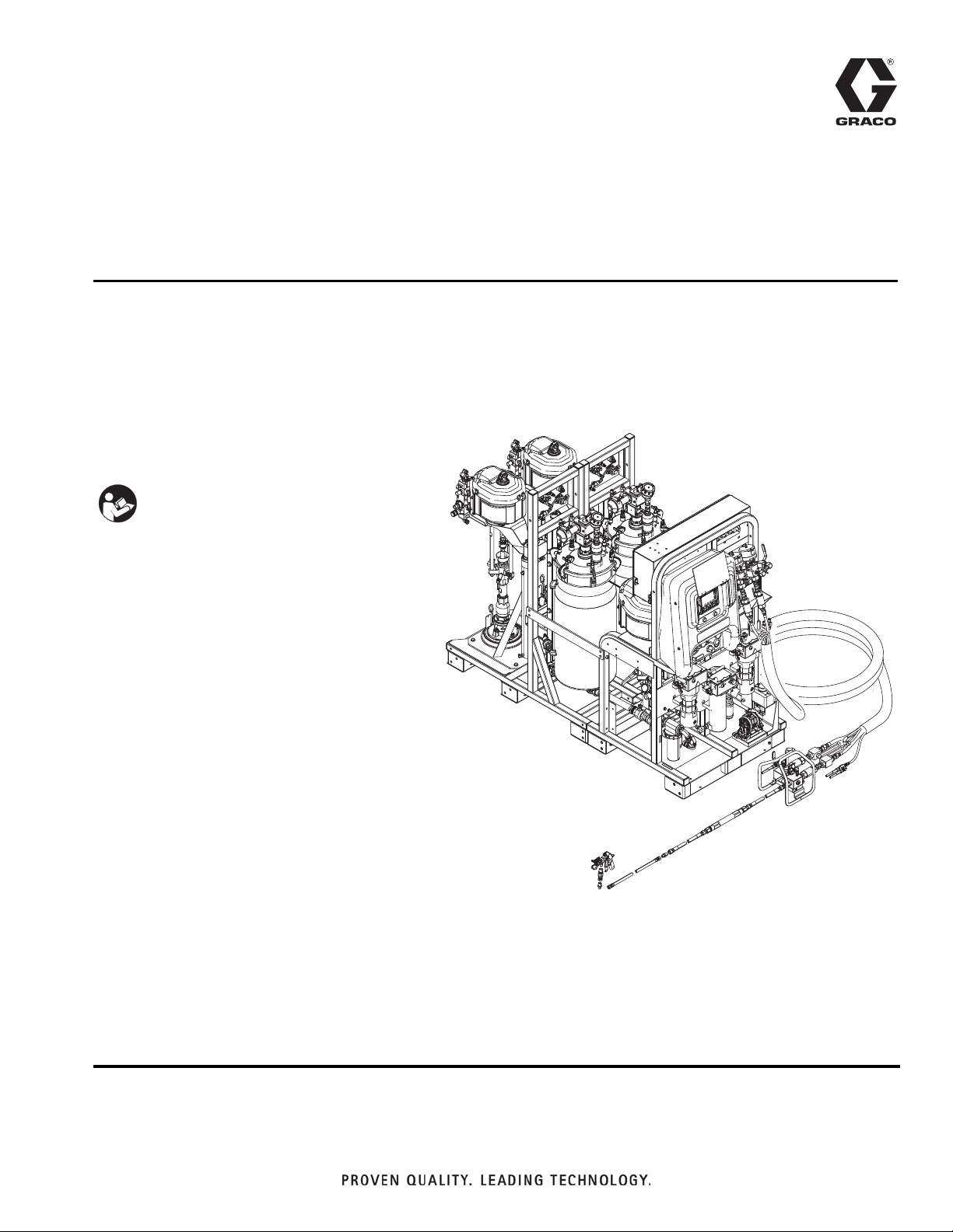
XM PFP
For spraying two-component intumescent epoxies. For professional use only.
Not for use in explosive atmospheres or hazardous locations.
Important Safety Instructions
Read all warnings and instructions in all
supplied manuals. Save all instructions.
3A2776D
EN
See page 3 for model information, including
maximum working pressure and approvals.
WLD
Page 2

Contents
Models . . . . . . . . . . . . . . . . . . . . . . . . . . . . . . . . . . . 3
Related Manuals . . . . . . . . . . . . . . . . . . . . . . . . . . . 3
Warnings . . . . . . . . . . . . . . . . . . . . . . . . . . . . . . . . . 4
Keep Components A and B Separate . . . . . . . . 6
Changing Materials . . . . . . . . . . . . . . . . . . . . . . . 6
Components A and B . . . . . . . . . . . . . . . . . . . . . 6
Component Identification . . . . . . . . . . . . . . . . . . . . 7
Typical Setup (Front View) . . . . . . . . . . . . . . . . . 7
Typical Setup (Back View) . . . . . . . . . . . . . . . . . 8
Fluid Control Assembly . . . . . . . . . . . . . . . . . . . . 9
Main Power and Heater Controls . . . . . . . . . . . 10
Sprayer and Flush Pump Air Controls . . . . . . . 10
Feed Module Air Controls . . . . . . . . . . . . . . . . 11
User Interface . . . . . . . . . . . . . . . . . . . . . . . . . 12
Setup . . . . . . . . . . . . . . . . . . . . . . . . . . . . . . . . . . . . 14
Location . . . . . . . . . . . . . . . . . . . . . . . . . . . . . . 14
Unboxing . . . . . . . . . . . . . . . . . . . . . . . . . . . . . . 14
Configuration Options . . . . . . . . . . . . . . . . . . . . 14
Grounding . . . . . . . . . . . . . . . . . . . . . . . . . . . . . 16
Connect Power . . . . . . . . . . . . . . . . . . . . . . . . 16
Connect Air Supply . . . . . . . . . . . . . . . . . . . . . . 17
Connect Feed Module Lines to Sprayer Module 18
Install Level Sensor Probe . . . . . . . . . . . . . . . . 19
Check Level Sensor Calibration . . . . . . . . . . . . 19
Connect the Fluid Hose Bundle to the System . 20
Connect the Fluid Hose Bundle to the
Mix Manifold . . . . . . . . . . . . . . . . . . . . . . . . 21
Connect the Mix Manifold to the Gun . . . . . . . . 22
Prime Heated Fluid Circulation System . . . . . . 23
Initial Startup . . . . . . . . . . . . . . . . . . . . . . . . . . . . . 24
Prime Solvent Flush Pump . . . . . . . . . . . . . . . . . . 29
Adjust Ratio and System Settings . . . . . . . . . . . . 31
Temperature Settings . . . . . . . . . . . . . . . . . . . . . . 31
Spray . . . . . . . . . . . . . . . . . . . . . . . . . . . . . . . . . . . . 32
Flush Mixed Material . . . . . . . . . . . . . . . . . . . . . . 36
Park Metering Pump Rods . . . . . . . . . . . . . . . . . . 37
Pressure Relief Procedure . . . . . . . . . . . . . . . . . . 38
System Verification . . . . . . . . . . . . . . . . . . . . . . . . 40
Pump and Metering Test . . . . . . . . . . . . . . . . . . 40
Batch Dispense or Ratio Test . . . . . . . . . . . . . . 42
Down Stream Valve Leak Test . . . . . . . . . . . . . 43
Mix and Integration Tests . . . . . . . . . . . . . . . . . 44
Empty and Flush Entire System . . . . . . . . . . . . . . 45
Prepare Level Sensor for Shipping . . . . . . . . . . . 49
Download Data from USB . . . . . . . . . . . . . . . . . . . 50
USB Logs . . . . . . . . . . . . . . . . . . . . . . . . . . . . . 50
Download Setup . . . . . . . . . . . . . . . . . . . . . . . . 50
Download Procedure . . . . . . . . . . . . . . . . . . . . . 50
Maintenance . . . . . . . . . . . . . . . . . . . . . . . . . . . . . . 52
Adjust Packing Nuts . . . . . . . . . . . . . . . . . . . . . 52
Filters . . . . . . . . . . . . . . . . . . . . . . . . . . . . . . . . . 52
Seals . . . . . . . . . . . . . . . . . . . . . . . . . . . . . . . . . 52
Clean the System . . . . . . . . . . . . . . . . . . . . . . . 53
Troubleshooting . . . . . . . . . . . . . . . . . . . . . . . . . . . 54
Alarms . . . . . . . . . . . . . . . . . . . . . . . . . . . . . . . . 54
General Tips . . . . . . . . . . . . . . . . . . . . . . . . . . . 54
Individual Control Module LED Diagnostic
Information . . . . . . . . . . . . . . . . . . . . . . . . . 55
Troubleshooting Table . . . . . . . . . . . . . . . . . . . 55
Appendix A - User Interface Display . . . . . . . . . . 58
Change a Setting . . . . . . . . . . . . . . . . . . . . . . . . 58
Alarms . . . . . . . . . . . . . . . . . . . . . . . . . . . . . . . . 58
Setup Mode Screens . . . . . . . . . . . . . . . . . . . . . 59
Operator Command Mode Screens . . . . . . . . . . 66
Automatically Displayed Screens . . . . . . . . . . . 73
Appendix B - Alarms . . . . . . . . . . . . . . . . . . . . . . . 75
Alarms Overview . . . . . . . . . . . . . . . . . . . . . . . . 75
Alarm Code Troubleshooting . . . . . . . . . . . . . . . 78
Technical Data . . . . . . . . . . . . . . . . . . . . . . . . . . . . 85
Dimensions . . . . . . . . . . . . . . . . . . . . . . . . . . . . 86
Graco Standard Warranty . . . . . . . . . . . . . . . . . . . 88
Graco Information . . . . . . . . . . . . . . . . . . . . . . . . . 88
2 3A2776D
Page 3
Models
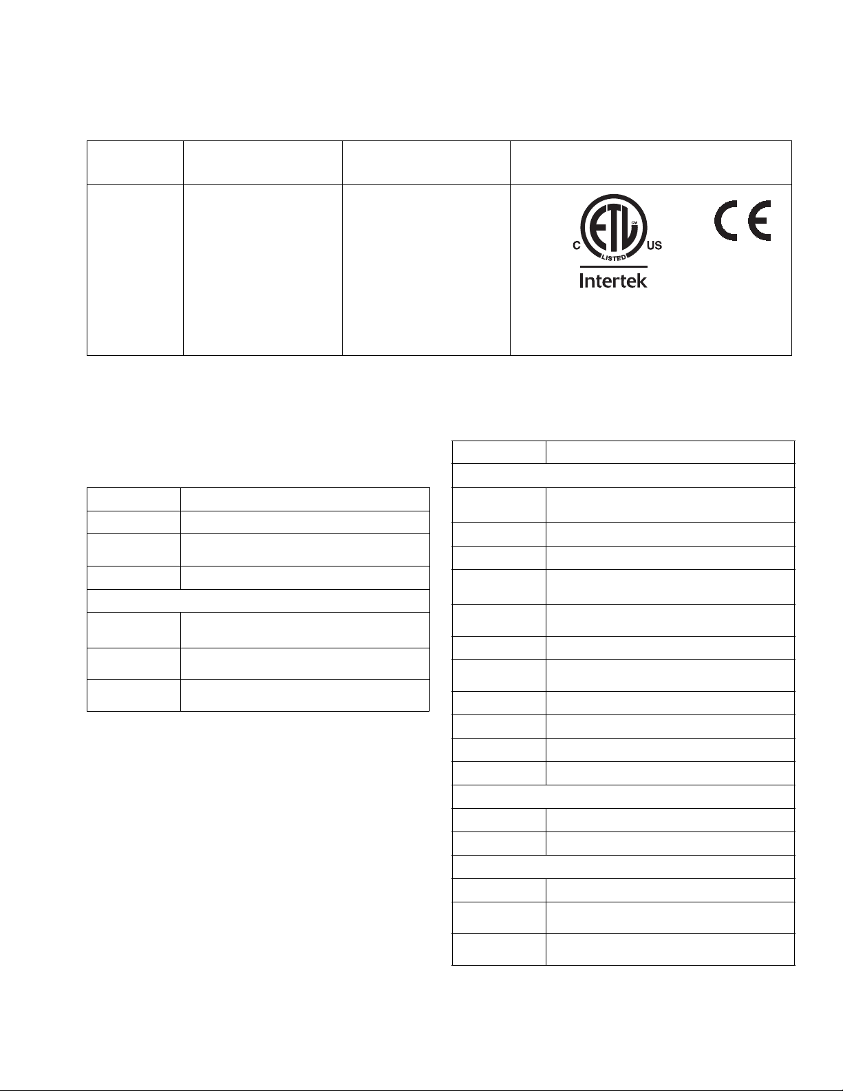
Models
Models
Maximum Fluid
Working Pressure
Maximum Air Working
Pressure Approvals
A and B Materials:
6000 psi
(41 MPa, 414 bar)
Supply:
262869
24W626
Flushing Fluid:
4500 psi
(31 MPa, 310 bar)
(1.0 MPa, 10.3 bar)
Max. Setpoint:
(0.7 MPa, 7 bar)
Heating Fluid:
100 psi
(0.7 MPa, 7 bar)
Related Manuals
Manuals are available at www.graco.com. Component
manuals in English:
Manual Description
3A2989 XM PFP Repair
3A2988
3A2799 XHF Spray Gun
Heaters
309524
3A2954
3A2824
XM PFP Mix Manifold Instructions Parts
Viscon
®
HP High Pressure Fluid
Heater Instructions - Parts
Viscon HF High Flow, High Pressure
Fluid Heater Instructions - Parts
Viscon LT Fluid Heater Instructions -
Parts
150 psi
100 psi
Certified to CAN/CSA C22.2 No. 88
9902471
Conforms to
UL 499
Manual Description
Pumps, Motors, Supply Systems
™
308652
311238
311762
312375
312376
312792
312794
Husky
Pumps Instructions - Parts
NXT
Xtreme
Check-Mate
Instructions - Parts
Check-Mate Pump Packages Instructions - Parts
Merkur
Merkur Pump Assembly Instructions -
Parts
205 Air-Operated Diaphragm
®
Air Motor Instructions - Parts
®
®
312796 NXT Air Motor Instructions - Parts
Lowers Instructions - Parts
®
Displacement Pumps
Pump Repair - Parts
313526 Supply Systems Operation
313527 Supply Systems Repair - Parts
312374 Air Control Instructions - Parts
Accessories
332073 Hot Water Flush Kit Instructions
3A2987 Air Dryer Kit Instructions
Other
306861 Ball Valves Instructions - Parts
307005
308169
3A2776D 3
High Pressure Swivel Instructions Parts
Air Filters, Lubricators, and Kits
Instructions - Parts
Page 4
Warnings
Warnings
The following warnings are for the setup, use, grounding, maintenance, and repair of this equipment. The exclamation point symbol alerts you to a general warning and the hazard symbols refer to procedure-specific risks. When
these symbols appear in the body of this manual or on warning labels, refer back to these Warnings. Product-specific
hazard symbols and warnings not covered in this section may appear throughout the body of this manual where
applicable.
WARNING
WARNINGWARNINGWARNING
ELECTRIC SHOCK HAZARD
This equipment must be grounded. Improper grounding, setup, or usage of the system can cause
electric shock.
• Turn off and disconnect power at main switch before disconnecting any cables and before servicing
or installing equipment.
• Connect only to grounded power source.
• All electrical wiring must be done by a qualified electrician and comply with all local codes and
regulations.
SKIN INJECTION HAZARD
High-pressure fluid from gun, hose leaks, or ruptured components will pierce skin. This may look like just
a cut, but it is a serious injury that can result in amputation. Get immediate surgical treatment.
• Do not spray without tip guard and trigger guard installed.
• Engage trigger lock when not spraying.
• Do not point gun at anyone or at any part of the body.
• Do not put your hand over the spray tip.
• Do not stop or deflect leaks with your hand, body, glove, or rag.
•Follow the Pressure Relief Procedure when you stop spraying and before cleaning, checking, or
servicing equipment.
• Tighten all fluid connections before operating the equipment.
• Check hoses and couplings daily. Replace worn or damaged parts immediately.
FIRE AND EXPLOSION HAZARD
Flammable fumes, such as solvent and paint fumes, in work area can ignite or explode. To help prevent
fire and explosion:
• Use equipment only in well ventilated area.
• Eliminate all ignition sources; such as pilot lights, cigarettes, portable electric lamps, and plastic drop
cloths (potential static arc).
• Keep work area free of debris, including solvent, rags and gasoline.
• Do not plug or unplug power cords, or turn power or light switches on or off when flammable fumes
are present.
• Ground all equipment in the work area. See Grounding instructions.
• Use only grounded hoses.
• Hold gun firmly to side of grounded pail when triggering into pail. Do not use pail liners unless they
are antistatic or conductive.
• Stop operation immediately if static sparking occurs or you feel a shock. Do not use equipment
until you identify and correct the problem.
• Keep a working fire extinguisher in the work area.
BURN HAZARD
Equipment surfaces and fluid that’s heated can become very hot during operation. To avoid severe
burns:
• Do not touch hot fluid or equipment.
4 3A2776D
Page 5
Warnings
WARNING
WARNINGWARNINGWARNING
MOVING PARTS HAZARD
Moving parts can pinch, cut or amputate fingers and other body parts.
• Keep clear of moving parts.
• Do not operate equipment with protective guards or covers removed.
• Pressurized equipment can start without warning. Before checking, moving, or servicing equipment,
follow the Pressure Relief Procedure and disconnect all power sources.
EQUIPMENT MISUSE HAZARD
Misuse can cause death or serious injury.
• Do not operate the unit when fatigued or under the influence of drugs or alcohol.
• Do not exceed the maximum working pressure or temperature rating of the lowest rated system
component. See Technical Data in all equipment manuals.
• Use fluids and solvents that are compatible with equipment wetted parts. See Technical Data in all
equipment manuals. Read fluid and solvent manufacturer’s warnings. For complete information
about your material, request MSDS from distributor or retailer.
• Do not leave the work area while equipment is energized or under pressure.
• Turn off all equipment and follow the Pressure Relief Procedure when equipment is not in use.
• Check equipment daily. Repair or replace worn or damaged parts immediately with genuine manufacturer’s replacement parts only.
• Do not alter or modify equipment. Alterations or modifications may void agency approvals and create
safety hazards.
• Make sure all equipment is rated and approved for the environment in which you are using it.
• Use equipment only for its intended purpose. Call your distributor for information.
• Route hoses and cables away from traffic areas, sharp edges, moving parts, and hot surfaces.
• Do not kink or over bend hoses or use hoses to pull equipment.
• Keep children and animals away from work area.
• Comply with all applicable safety regulations.
TOXIC FLUID OR FUMES HAZARD
Toxic fluids or fumes can cause serious injury or death if splashed in the eyes or on skin, inhaled, or
swallowed.
• Read MSDSs to know the specific hazards of the fluids you are using.
• Store hazardous fluid in approved containers, and dispose of it according to applicable guidelines.
PERSONAL PROTECTIVE EQUIPMENT
Wear appropriate protective equipment when in the work area to help prevent serious injury, including
eye injury, hearing loss, inhalation of toxic fumes, and burns. This protective equipment includes but is
not limited to:
• Protective eyewear, and hearing protection.
• Respirators, protective clothing, and gloves as recommended by the fluid and solvent manufacturer
SPLATTER HAZARD
Hot or toxic fluid can cause serious injury if splashed in the eyes or on skin. During blow off of platen,
splatter may occur.
• Use minimum air pressure when removing platen from drum.
3A2776D 5
Page 6

Warnings
Keep Components A and B Separate
Cross-contamination can result in cured material in
fluid lines which could cause serious injury or damage
equipment. To prevent cross-contamination:
• Never interchange component A and component
B wetted parts.
• Never use solvent on one side if it has been contaminated from the other side.
Changing Materials
NOTICE
Changing the material types used in your equipment
requires special attention to avoid equipment damage
and downtime.
• When changing materials, flush the equipment
multiple times to ensure it is thoroughly clean.
Components A and B
IMPORTANT!
Material suppliers can vary in how they refer to plural
component materials.
Be aware that in this manual:
Component A
Component B
This equipment doses the B component into the A component flow. An integration hose must always be used
after the mix manifold and before the static mixer.
refers to resin or major volume.
refers to the hardener or minor volume.
• Always clean any fluid inlet strainers after flushing.
• Check with your material manufacturer for chemical compatibility.
• When changing between epoxies and urethanes
or polyureas, disassemble and clean all fluid components and change hoses. Epoxies often have
amines on the B (hardener) side. Polyureas often
have amines on the B (resin) side
6 3A2776D
Page 7
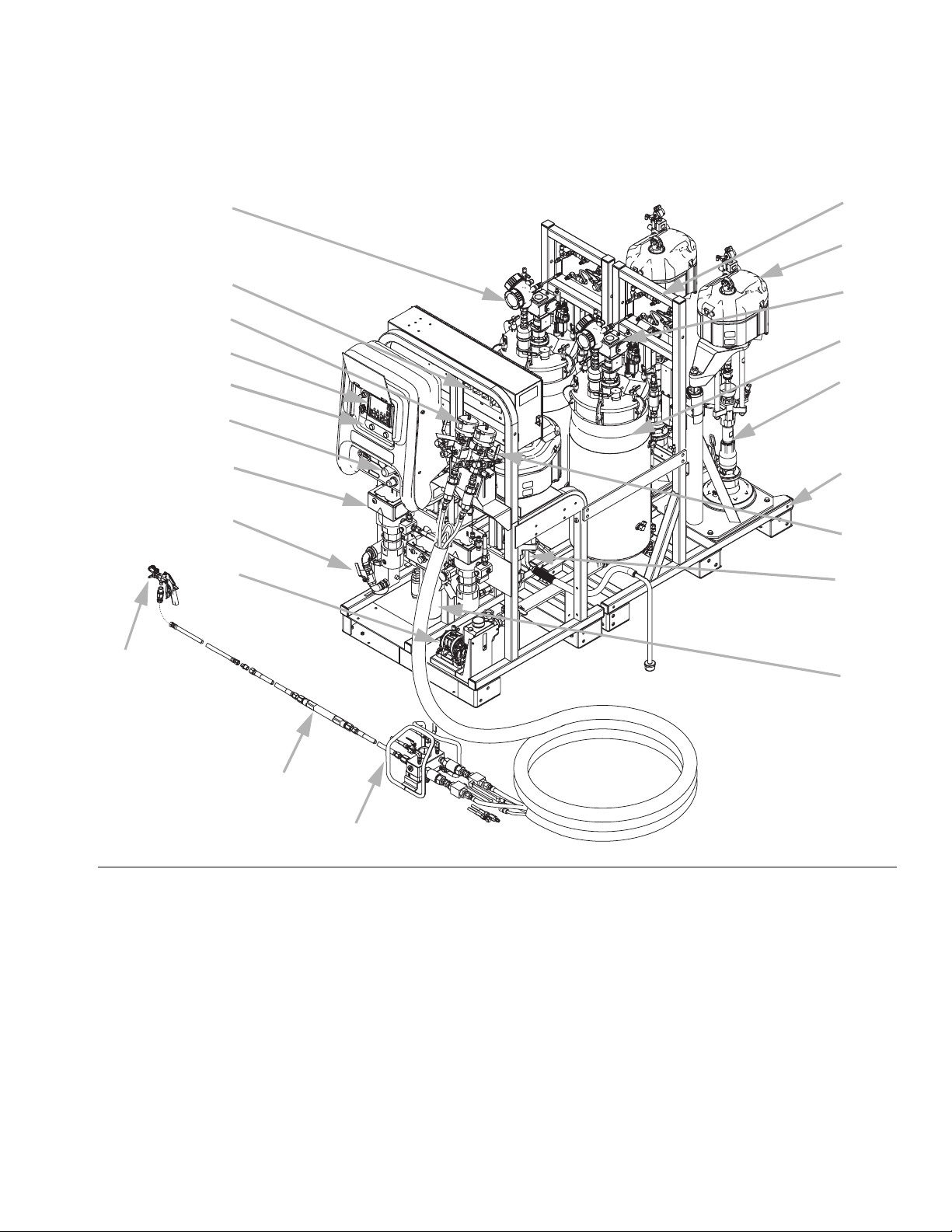
Component Identification
Typical Setup (Front View)
Y
Component Identification
V
U
J
B
C
D
G
K
E, F
C1
T
ti19927a
WLE
L
P
M
A
N
X
H
S
R
FIG. 1
Key:
AFrame
B Fluid Control Assembly
C GCA Control Display
D Metering Pumps Control On and Off Buttons
E Main Air Supply Shutoff Valve, 1 in. npt(f) Inlet
F Air Filter, 1-1/4 in.
G Air Controls for Sprayer and Flush Pump (see page 10)
H Viscon HP Heater for hose bundle
J Junction Box/Heater Controls (see page 10)
K Viscon HF Material Heater
L Air Powered Agitator with Lubricator
M Feed Pump
N Recirculation Control Valve
P Pressure Tank, Double-Wall Temperature Conditioned
3A2776D 7
R Remote Mix Manifold
S Static Mixer Assembly
T Spray Gun
U Air Motor
V Supply Controls (see page 11)
W High Pressure Fluid Metering Pump
X Solvent Flush Pump (Merkur Pump)
Y Radar Fluid Level Sensor
Z Air Regulator for Feed Tanks and Pumps
A1 Heated Tank Circulation Components (uses a Viscon LT)
B1 TSL Supply Bottle and Bracket
C1 Heated Fluid Circulation Pump for Hose Bundle
D1 Insulation Jacket
Page 8
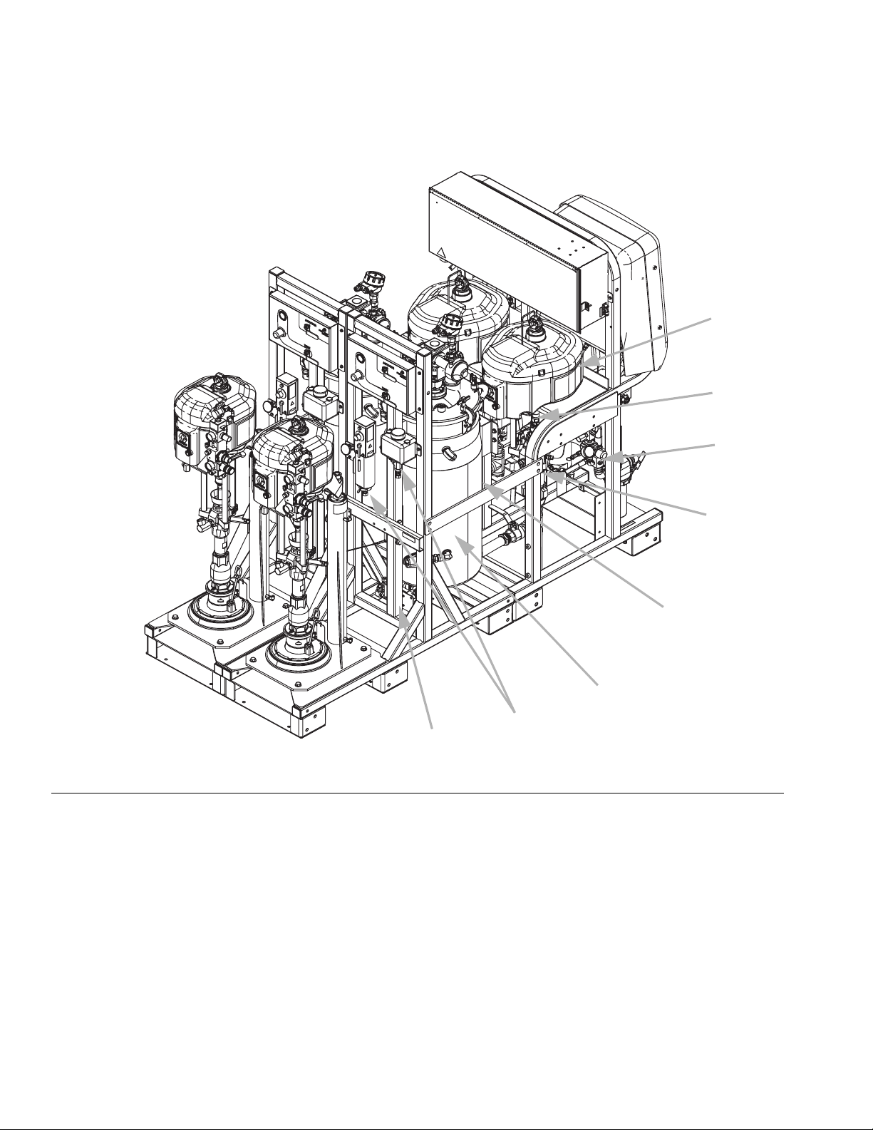
Component Identification
Typical Setup (Back View)
U
B1
Z
FIG. 2
C1, A1
A1
WLD
W
X (located between
metering pumps, not
visible in current view)
D1, A1
8 3A2776D
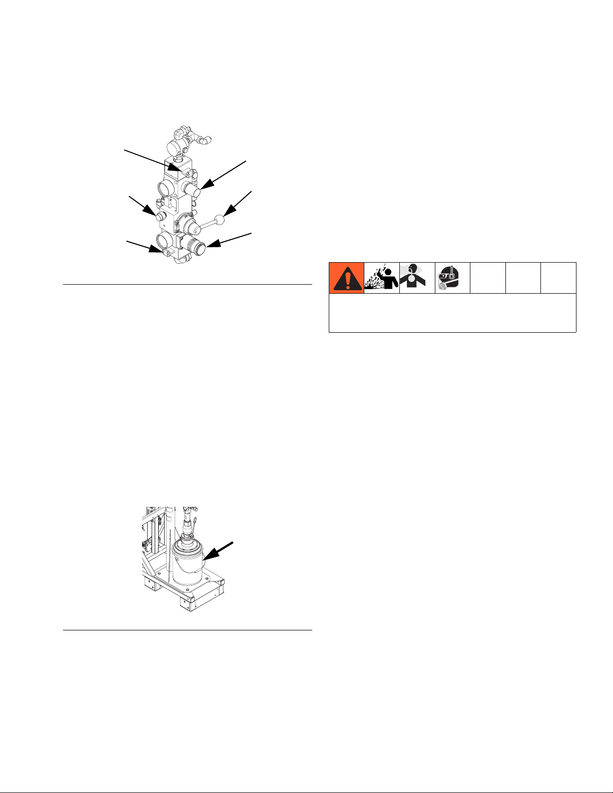
Page 9
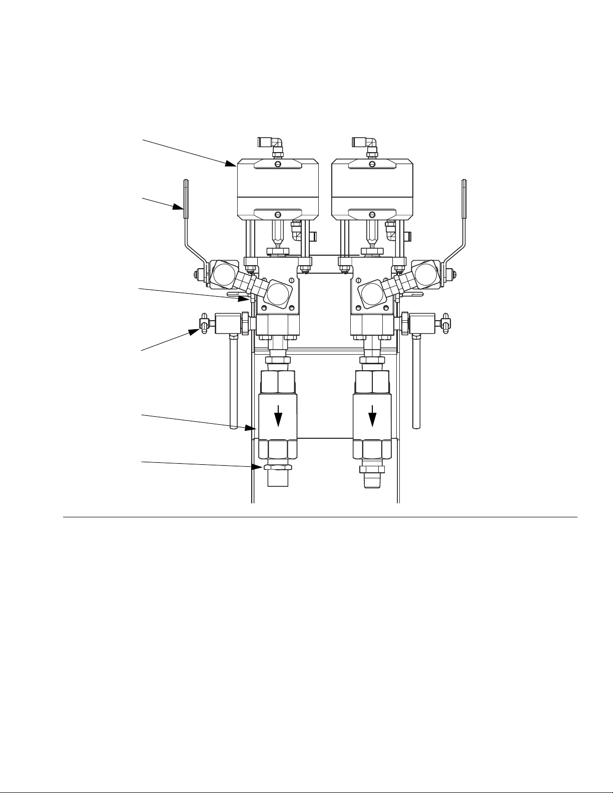
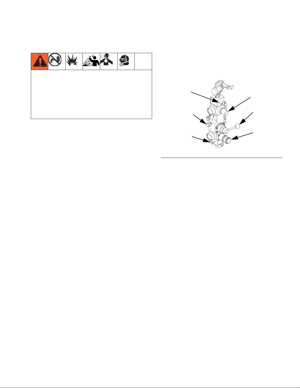
Fluid Control Assembly
AA
AC
AL
Component Identification
AE
AG
AJ
FIG. 3
AA Dosing Valve
AC Recirculation Valve
AE Sampling Valve
AG Outlet Check Valve
AJ Hose Connection (Model 262869) - A side: 3/4 npt(m); B side: 1/2 npt(m)
Hose Connection (Model 24W626) - A side: 3/4 npt(m); B side 3/4 npt(m)
AL Pressure Sensor
ti19928a
3A2776D 9
Page 10
Component Identification
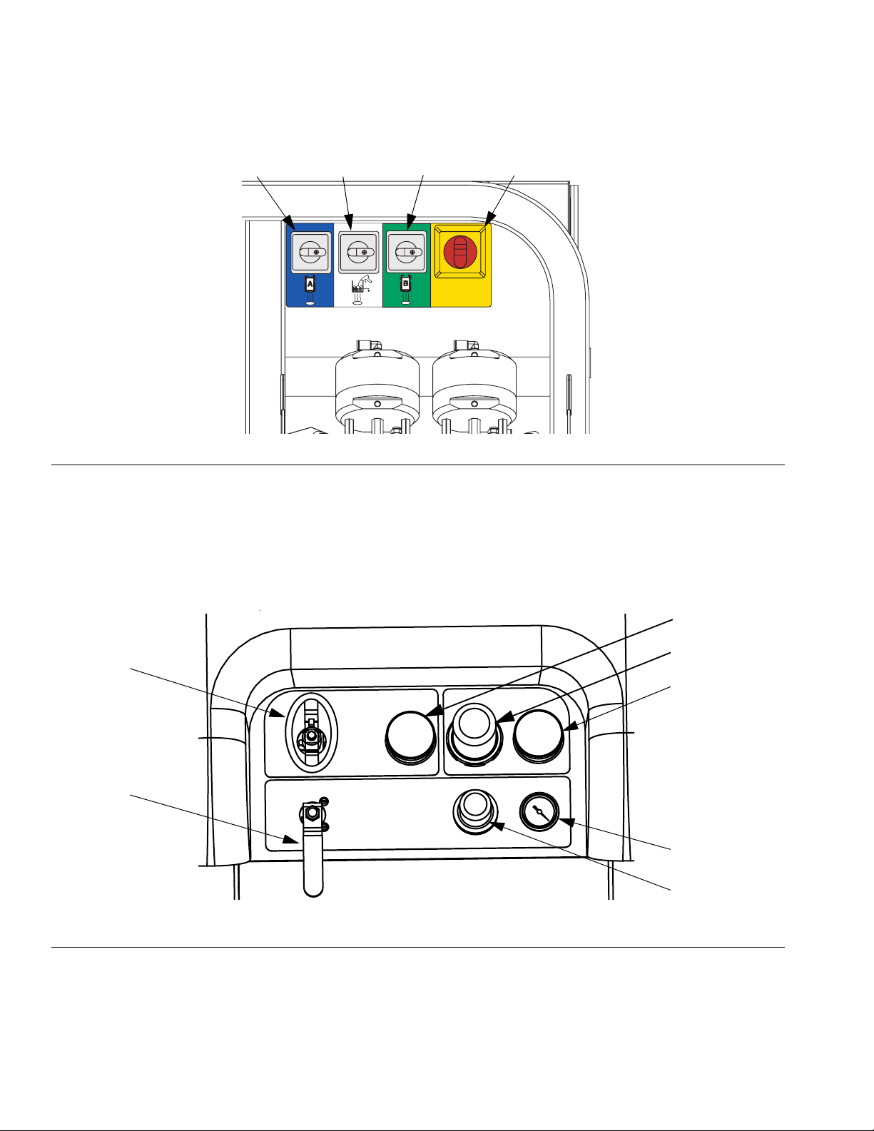
Main Power and Heater Controls
BB BCBD BA
FIG. 4
ti20101a
BA Main Power ON/OFF Switch
BB A Tank Water Heat ON/OFF Switch
BC B Tank Water Heat ON/OFF Switch
BD Optional Heated Water Flush Tank Accessory ON/OFF
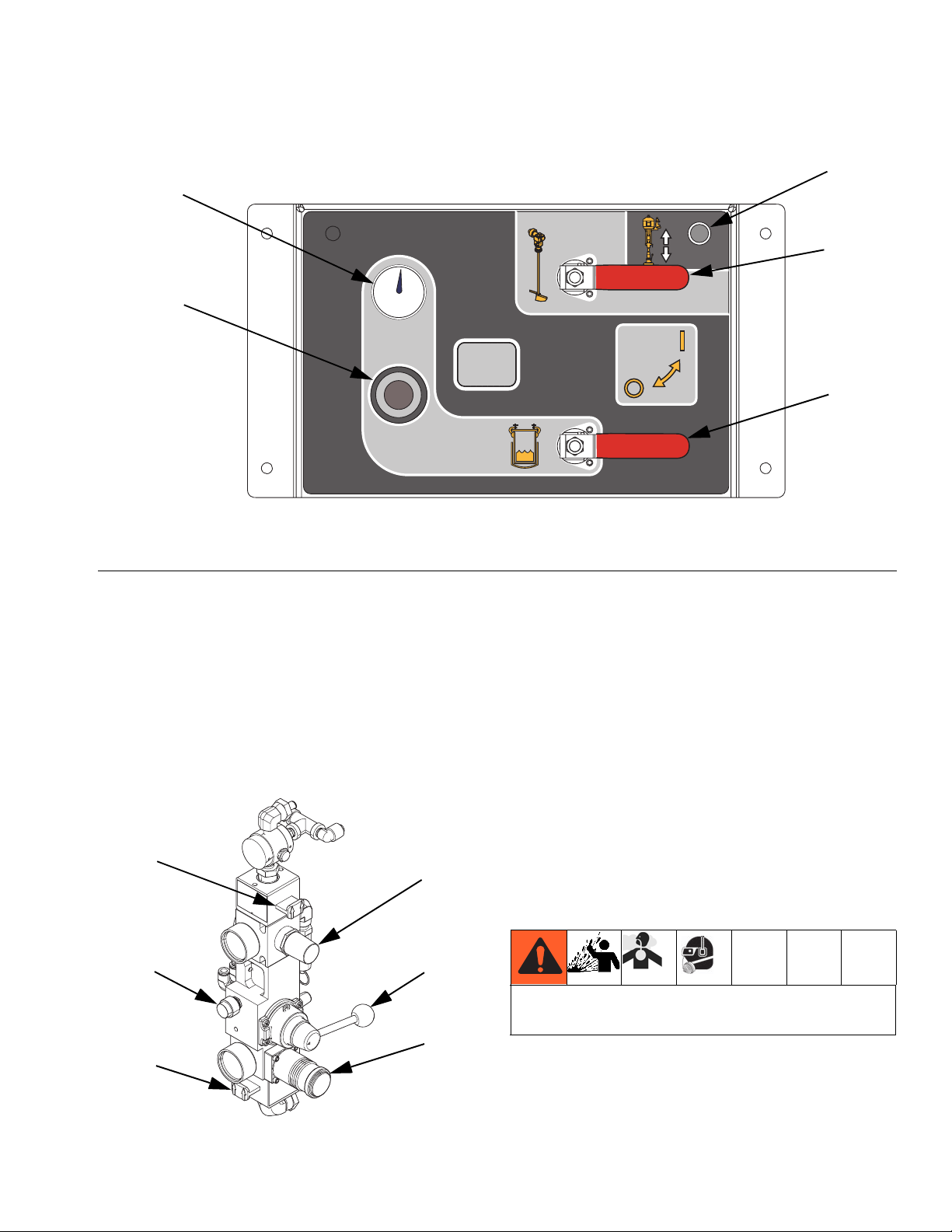
Sprayer and Flush Pump Air Controls
CA
CB
FIG. 5
Switch (only used if the water heater accessory has been
added to the machine)
CC
CD
CE
CF
CG
r_XM1A00_312359_313289_14A
CA Metering Pump Air On/Off Control
CB Solvent Pump Air On/Off Control
CC Inlet Air Pressure Gauge
CD Metering Pump Air Regulator
CE Metering Pump Air Regulator Gauge
10 3A2776D
CF Solvent Pump Air Gauge
CG Solvent Pump Air Regulator
Page 11
Feed Module Air Controls
CR
Component Identification
CU
CP
NOTE: Both valves shown open
F
IG
. 6: Supply Controls
CP Tank Air Pressure Regulator
CR Tank Air Pressure Gauge
CS Tank Air Supply Valve
CT Agitator and Heated Water Circulation On/Off Valve
CU Feed Pump Bypass Button
FEED PUMP
BYPASS
ti20127a
CT
CS
Feed Pump Bypass Button
Use the feed pump bypass button to manually run the
feed pump when the automatic tank filling function is not
running the feed pump. See automatic tank filling details
on page 73.
Feed Pump Air Controls
DF
DA RAM Air ON/Exhaust Slider Valve
DB RAM Air Regulator
DC RAM Up/Down Director Valve
DD RAM Blowoff Valve
DE Air Motor Regulator
DF Air Motor ON/Exhaust Slider Valve
DE
RAM Blowoff Valve (DD)
DD
DC
To minimize material splatter, use the minimum air
pressure required to remove platen from pail.
DB
DA
To easily remove the RAM from the pail, press and hold
the RAM Blowoff Valve button while lifting the RAM
platen. A small amount of air pressure will be supplied to
ti20104a
3A2776D 11
the pail to push the pail off of the RAM.
Page 12
Component Identification
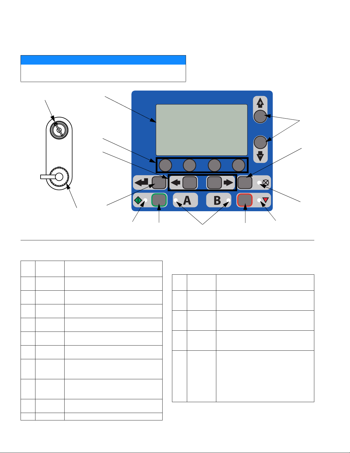
User Interface
NOTICE
To prevent damage to soft key buttons, do not press the buttons
with sharp objects such as pens, plastic cards, or fingernails.
DJ
DR
DA
DG
DF
DD
ti13365a
DH
DE
DP
F
IG
. 7: User Interface
DM
DB
Buttons LEDs
Call
out Button Function
DA Display
Screen
DB Start Initiates Active Run Mode function cur-
DC Stop Terminates Active Run Mode function
DD Enter Press to open drop-down fields, select
DE Alarm
Reset
DF Left/Right Move between screens in run or setup
DG Function Activates mode or action represented by
DH Up/Down Move between drop-down fields, option
DJ Setup Key
Lock
DR USB Port Connection for data download.
Use to view screens. See page 58.
rently selected in Run Screen.
currently selected.
options, and save values.
Resets alarms and advisories.
modes.
the icon above each of the four buttons in
the LCD.
boxes, and selectable values within
Setup screens.
Change ratio or enter Setup mode.
There are four types of LEDs on the display.
Call
out LED Function
DK Blue Dosing valve active
DM Green Spray mode active
DN Red Alarm
DP Yellow Warning
DK
DC
• On - dosing valve is active
• Off - dosing valve is not active
• Spray mode is on (active)
• Spray mode is off (inactive)
• On - alarm is present
• Off - no alarm
• On - is active.
• Off - no warning indicated. Ratio
and setup fields are not changeable.
• Flashing - key is present and
turned. Ratio and setup fields
are changeable.
DN
12 3A2776D
Page 13
Component Identification
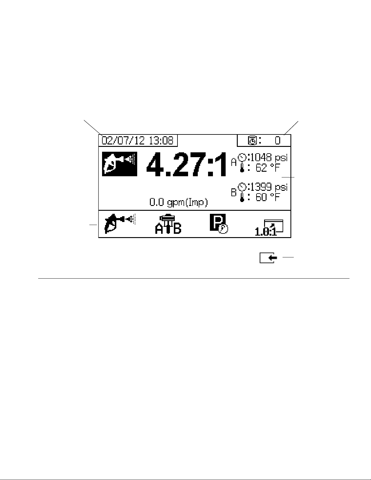
User Interface Display
Main Display Screen Components
NOTE: For detailed screens information, see Appendix A - User Interface Display beginning on page 58.
The following figure calls out the navigational, status, and general informational components of each display screen.
Current Date and Time
Navigational Bar
F
IG
. 8: Main Display Screen Components (shown with all display features enabled)
Remaining Potlife Time
Function Display
Go back one screen
3A2776D 13
Page 14
Setup
Setup
Location
Select a non-hazardous location with the required power
and air supply to set up your sprayer. Maintain access
from all sides.
Unboxing
The machine is shipped on two separate pallets, one
with the XM PFP and one with the two feed modules.
Each pallet is wrapped in heavy cardboard with a lid
secured with straps. Cut the lid straps then remove the
lids and cardboard.
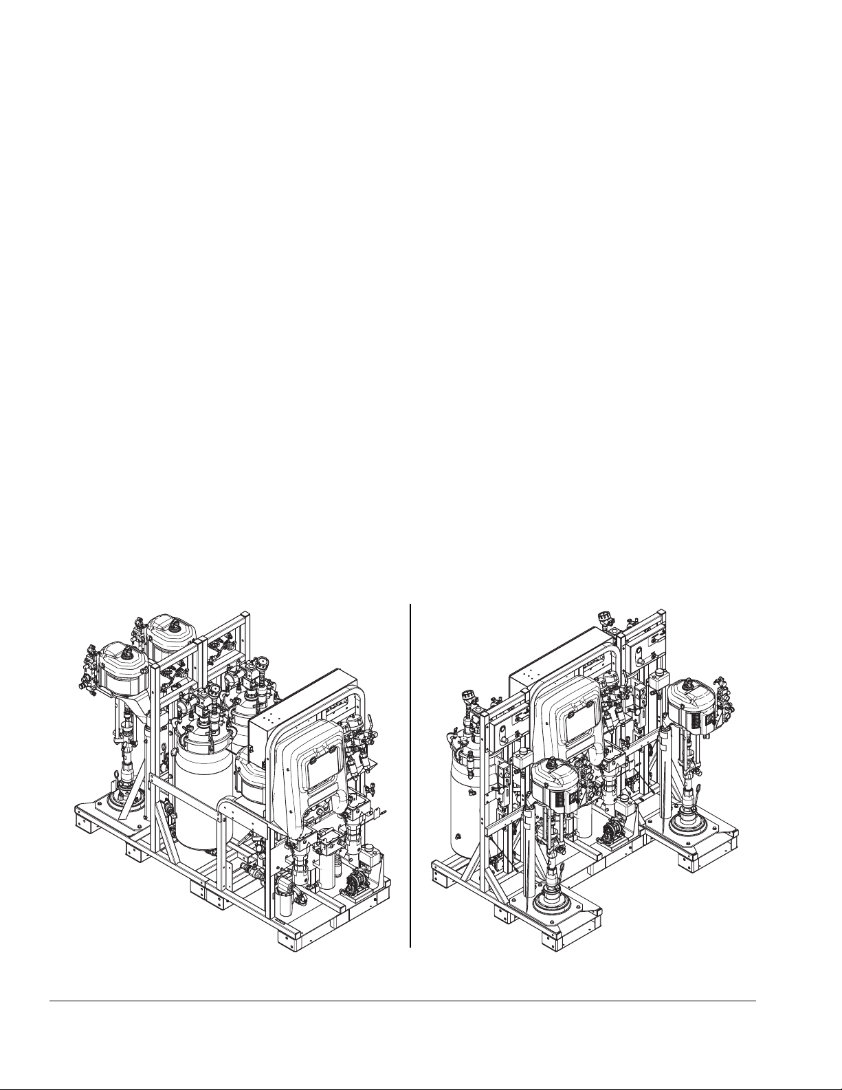
Configuration Options
The system can be laid out two ways:
• Side by side: where the feed modules are on either
side of the system module
• Front to back: where the feed modules are behind
the system module
Front to Back Configuration
Side by Side Configuration
ti20267a
F
IG
. 9
14 3A2776D
ti20268a
Page 15
Connect Modules
Regardless of the chosen module configuration, the A
feed module must be on the left and the B feed module
must be on the right when looking at the front of the system module. The A module has a blue A sticker on the
air control panel and a 1/2 in. return fitting into the tanks.
The B module has a green B sticker on the air control
panel and a 3/8 in. return fitting into the tanks.
Setup
5.5 in. long
1x
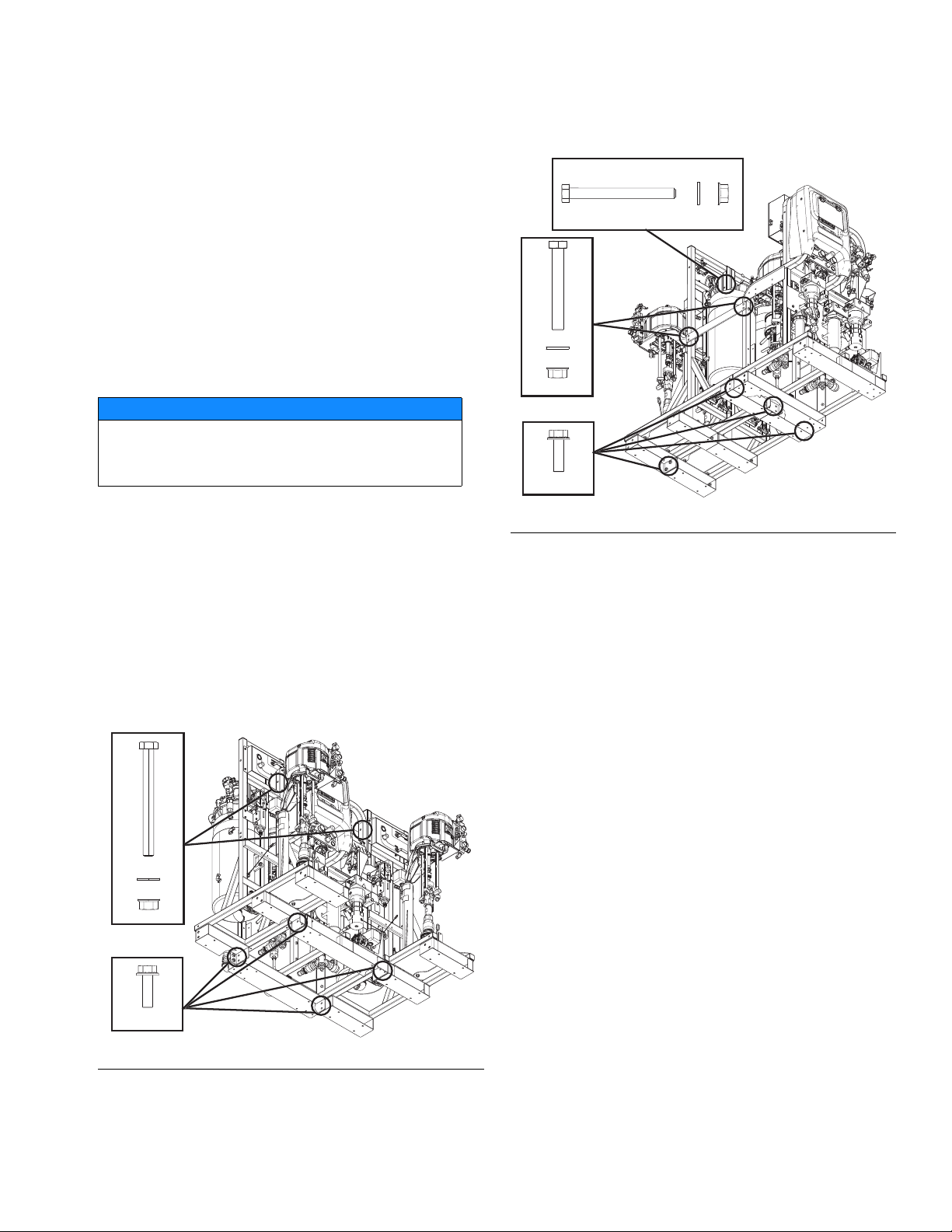
Choose one of the configurations shown in F
IG
. 9 then
bolt together the three modules on a flat surface. See
F
IG
. 10 or FIG. 11 for bolt locations. The frame bolts are
included in a bag. Once connected, the assembly can
be moved as one piece with a fork-truck.
NOTICE
Do not use lift rings to lift the entire assembly. This
will damage the system. The system must be lifted
from the bottom.
If the modules will not be connected, they must be within
12 in. of each other and in one of the two configurations
in F
IG
. 9 to ensure hoses and cables can reach their
connections.
If the front-to-back module configuration is used, install
the two supplied straight steel braces between each
feed module and the sprayer module, see F
IG
. 11.
These are not used in the side-by-side module configuration.
4x
3.5 in. long
ti20197a
10x
FIG. 11: Bolt Locations (Front to Back)
2x
5.5 in. long
8x
1.5 in. long
F
IG
. 10: Bolt Locations (Side by Side)
3A2776D 15
ti20163a
Page 16
Setup
Grounding
The equipment must be grounded to reduce the risk
of static sparking and electric shock. Electric or static
sparking can cause fumes to ignite or explode.
Improper grounding can cause electric shock.
Grounding provides an escape wire for the electric
current.
Ground the electrical connection properly according to
local codes.
Connect Power
Power must be connected by a qualified electrician.
Graco does not supply heater junction box power cords.
Use the following chart to determine which power cord
your system requires.
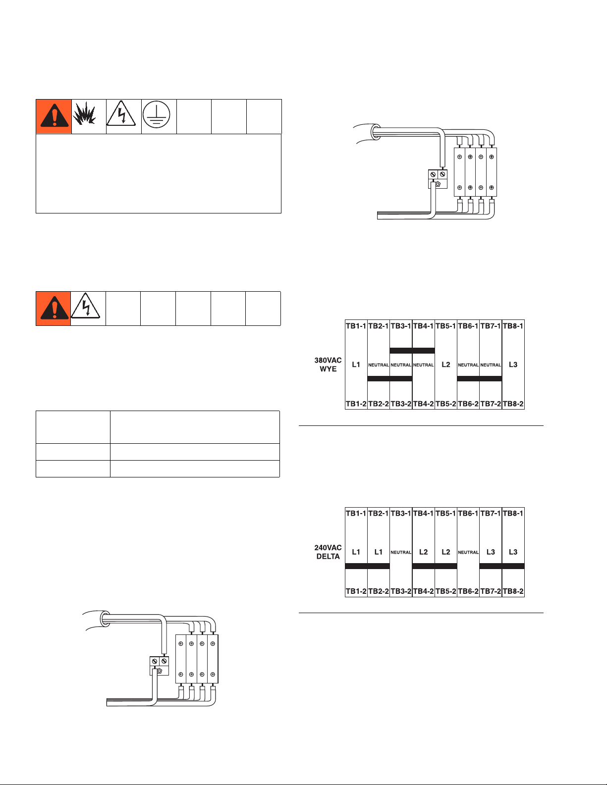
380V, 3 Phase WYE: Use a 5/32 in. (4 mm) hex key to
connect the three power leads to the top terminals L1,
L2, and L3. Connect neutral to N. Connect green to
ground (GND).
7L4
N L1 L2 L3
1L1
ti8613a1
4. Find the red power jumpers in the terminal blocks
supplied in a plastic bag in the junction box.
5.
For 380V, 3 Phase installations only,
use pliers to
install the red power jumpers into the terminal
blocks in the correct positions as shown in the following illustration. Push jumpers firmly into position.
Power Cord Requirements
System
Voltage Cord Specification AWG (mm
2
)
240V, 3 PH 6 (13.3) 3 wire + ground
380V, 3 PH 6 (13.3) 4 wire + ground
1. Open junction box cover.
2. Insert power cord through the large empty strain
relief in the bottom of the junction box.
3. Connect power cord as follows.
230V, 3 Phase Delta: Use a 5/32 in. (4 mm) hex key to
connect the three power leads to top terminals L1, L2,
and L3. Connect green to ground (GND).
L1 L2 L3N
1L1
FIG. 12
6.
For 240V, 3 Phase installations only,
use pliers to
install the red power jumpers into the terminal
blocks in the correct position as shown in the following illustration. Push jumpers firmly into position.
F
IG
. 13
7. Close junction box cover.
ti8612a1
16 3A2776D
Page 17

Connect Air Supply
Connect air supply line to the 1 in. npt(f) air supply ball
valve inlet.
NOTE:
Use a 3/4 in. (19.1 mm) ID minimum air hose.
E
ti20105a
NOTE:
Air supply requirement:
maximum; 80 psi (552 kPa, 5.5 bar) minimum (while
running).
150 psi (1.0 MPa, 10.3 bar)
Setup
Flow volume required:
250 scfm (7.1 m
100 scfm (2.8 m3/min) minimum;
3
/min) maximum. Available fluid pressure and flow rate are directly related to available air
volume. A typical single gun XM PFP application will use
125 to 175 scfm (3.5 to 5.0 m
3
/min).
NOTE:
Dosing valves are operated by air. The sprayer will not
operate correctly if the inlet air pressure drops below
80 psi (552 kPa, 5.5 bar) while spraying.
3A2776D 17
Page 18
Setup
Connect Feed Module Lines to Sprayer Module
1. Connect Modules, page 15.
2. Connect the large diameter green hose from each
tank bottom outlet to the respective metering pump
inlet.
NOTE: There is a vertical swivel union at each end of
the green hose assembly.
NOTE: If desired, the green hose can be trimmed to fit
better.
a. Loosen the tank end of the hose before trying to
connect to the metering pump inlet.
b. Bend the hose as necessary to make it fit.
c. Once the vertical unions are tightened, check
that the hose clamps on the green hose are
tightened to approximately 90-100 in-lb
(10-11 N•m).
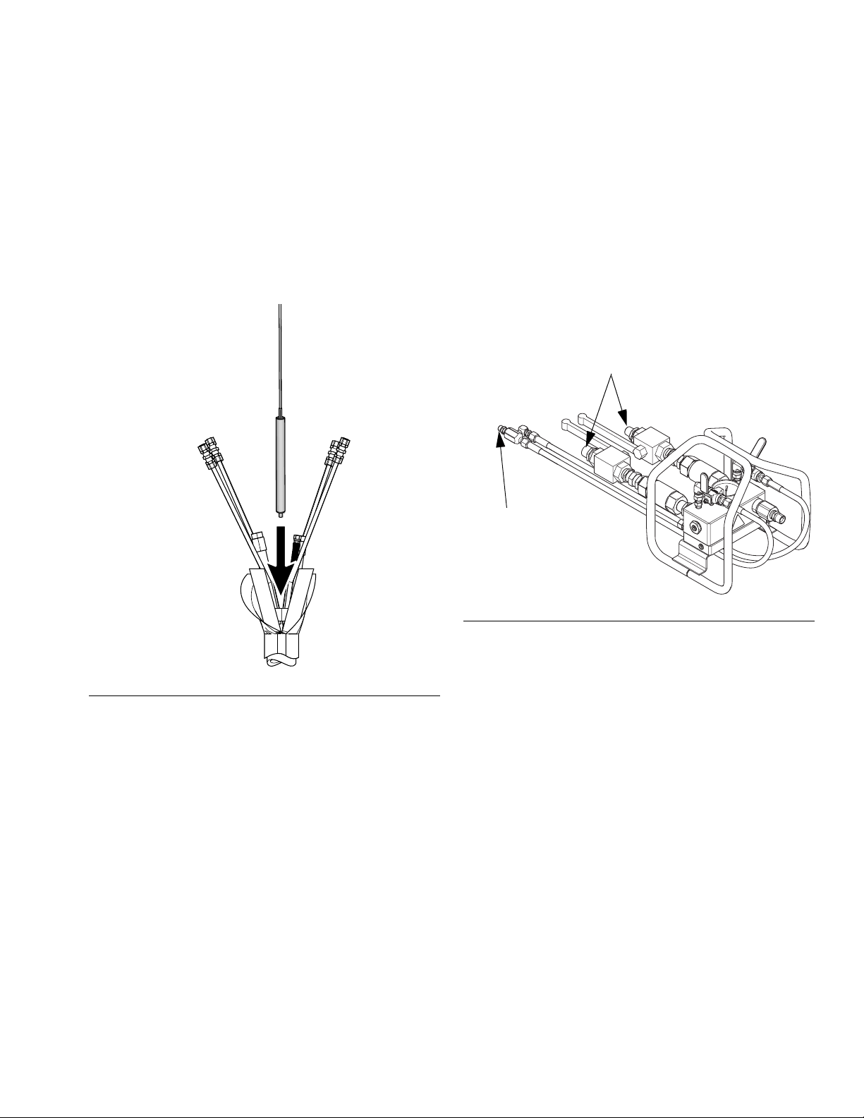
3. Connect the two hose bundles with a red air hose
on the sprayer module to the correct connection on
the respective feed module, as described below.
a. Connect the red 1/2 in. air hose to the swivel
union. See the ‘a’ in F
e
IG
. 14.
ti20269a
a
c
d
b
F
IG
. 14
b. Connect the 1/4 in. OD air signal tube to the
tube with a tube connector. This is the feed
pump pilot signal. See the ‘b’ in F
c. Connect the small cable with an M8 connector
to the mating M8 connector. See the ‘c’ in F
14.
d. Connect the larger cable with an M12 connector
to the mating M12 connector. This is the level
sensor connection. See the ‘d’ in F
e. Connect heater power cable to the mating
power connector. See the ‘e’ in F
4. Connect the fluid circulation return hoses.
• The 1/2 in. circulation hose from the dosing
valve connects to the side of the A tank.
• The 3/8 in. circulation hose from the dosing
valve connects to the side of the B tank.
IG
IG
. 14.
IG
. 14.
. 14.
IG
.
18 3A2776D
Page 19
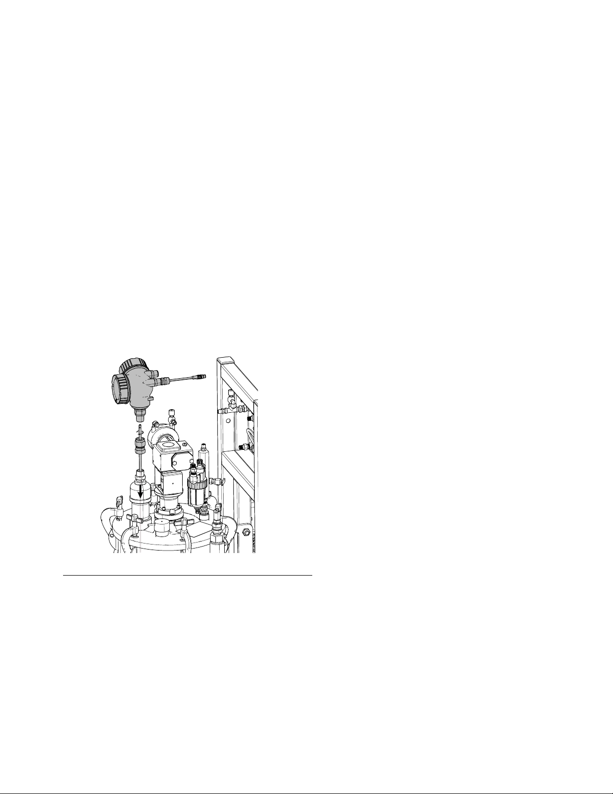
Install Level Sensor Probes
Each tank uses a 37 in (94 cm) stainless steel rod,
which functions as the level sensor probe, that mounts
into the level sensor head and extends down into the
tank. The level sensor probes are tie-wrapped to the
frame of each feed module at the factory prior to shipment. The level sensor probes must be mounted into the
level sensor heads before use.
1. Verify the main power switch is OFF.
2. Disconnect 3/4 in. union that holds the level sensor
on top of the tank.
3. Apply blue thread lock to the threads in the top of
the rod.
4. Feed the rod into the tank and screw the threaded
end up into the sensor head.
5. Use a pliers to grab the flat on the rod and tighten
the rod up into the sensor head. Do not over-tighten.
Setup
WLD
IG
. 15
F
Level Sensor Calibration
Level sensors are factory set to work with these tanks.
Calibration is not necessary unless replacing a sensor.
See manual 3A2989.
3A2776D 19
Page 20
Setup
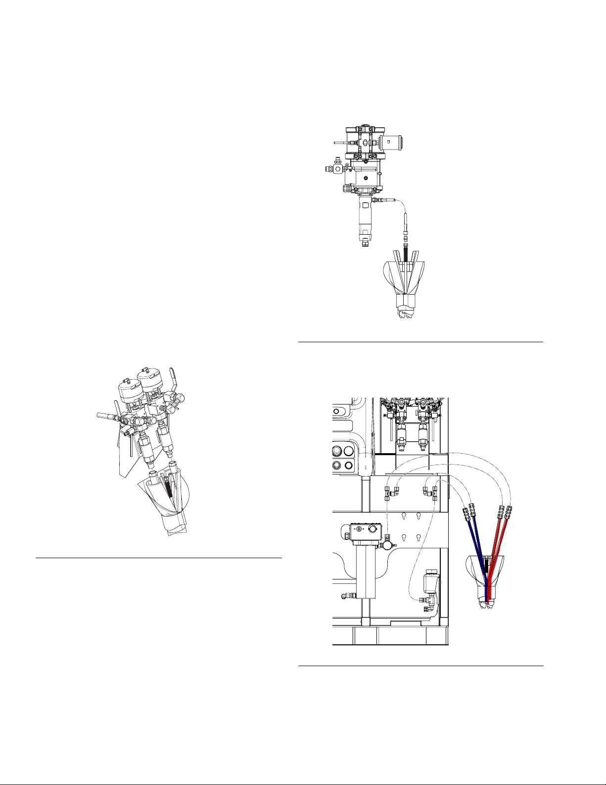
Connect the Fluid Hose Bundle to the System
The system is shipped with a 50 ft (15 m) hose bundle
for connecting the system to the mix manifold.
The bundle contains one 3/4 in. ID A material hose, one
1/2 in. ID B material hose (model 262869) one 3/4 in. ID
B material hose (model 24W626), one 1/4 in. ID flush
hose, and 1/2 in. OD heated fluid circulation tubes. The
hose bundle is insulated and wrapped inside a protective sheath which has a Velcro closure so it can be
opened to change hoses.
1. Position the hose bundle end with the four loose red
and blue tubes at the machine outlet.
Model 262869: Connect the 3/4 in. A and 1/2 in. B
hoses to the respective material outlet check valves
on the front of the system. See F
Model 24W626: Connect the 3/4 in. A and 3/4 in. B
hoses to the respective material outlet check valves
on the front of the system. See F
IG
IG
. 16.
. 16.
2. Connect the short purple flush hose from the solvent
flush pump to the 1/4 npsm hose in the bundle. Use
the 1/4 in. nipple included with the hose bundle to
connect the hoses. See F
IG
. 17.
ti20272a
FIG. 17: Solvent Flush Pump Connection
3. Connect the two red tubes in the bundle to the tube
tee on the red tube on the front of the machine. Do
the same for the blue tubes. See F
IG
. 18.
ti20106a
F
IG
. 16
ti20273a
IG
. 18
F
20 3A2776D
Page 21
Setup
4. Locate the long temperature sensor with black heat
shrink sheath and a connected cable that is
tie-wrapped to the B heater power cable.
a. Cut the temperature sensor loose from the tie
wrap.
b. Insert the sensor down inside the hose bundle
so it is buried in the insulation and up against
the fluid hoses. Be sure the sensor cable will not
get pulled tight by the hose or catch on anything.
Connect the Fluid Hose Bundle to the Mix Manifold
1. Unroll the hose bundle out to the spray area.
2. Model 262869: Connect the 3/4 in. A and 1/2 in. B
hoses to the material inlet ball valves on the mix
manifold. See F
Model 24W626: Connect the 3/4 in. A and 3/4 in. B
hoses to the material inlet ball valves on the mix
manifold. Color code material hoses (green and
blue) with respective color identification on mix
manifold. See F
IG
. 20.
IG
. 20.
Material Inlets
ti20274a
F
IG
. 19
c. Use electrical tape to wrap the hose bundle
from where it connects to the system to the
hose sheath. This insulates and protects the
hose bundle.
Solvent Inlet
ti20088a
FIG. 20
3. Remove the U-shaped tube connectors only from
the end of the longer set of red and blue tubes. Trim
the excess tubing to fit the one set of the red and
blue tubes fully into the two brass compression fittings on the aluminum heat circulation plate under
the main manifold. Tighten the compression fittings.
4. Route the purple solvent flush hoses from the manifold underneath the manifold carriage and connect
to the 1/4 in. flush hose in the hose bundle.
See F
IG
. 20.
5. Use electrical tape to wrap the hose bundle from
where it connects to the system to the hose sheath.
This insulates and protects the hose bundle.
3A2776D 21
Page 22

Setup
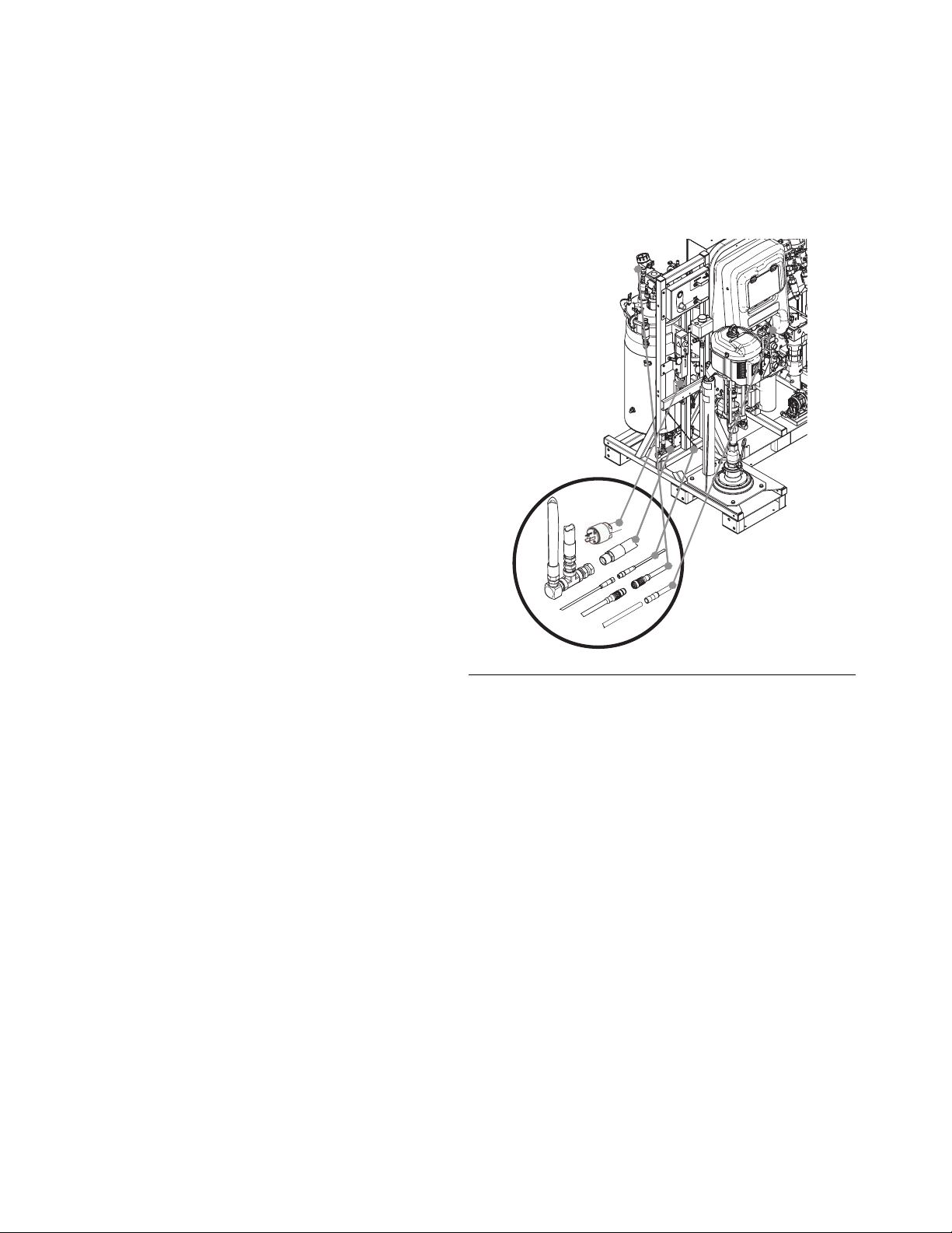
Connect the Mix Manifold to the Gun
The following parts are supplied loose. Connect them to
the mix manifold as follows. See F
1. Connect 1/2 in. ID x 2 ft hose to mix manifold (R)
outlet.
R
IG
. 21.
S
T
F
IG
. 21
2. Connect static mixer (S).
3. Connect 1/2 in. ID x 10 ft. hose.
4. Connect 1/2 in. x 3/8 in. nipple.
5. Connect 3/8 in. ID x 3 ft hose.
6. Connect 1/2 x 3/8 nipple.
7. Connect swivel.
8. Connect gun (T).
ti20090a
22 3A2776D
Page 23
Setup
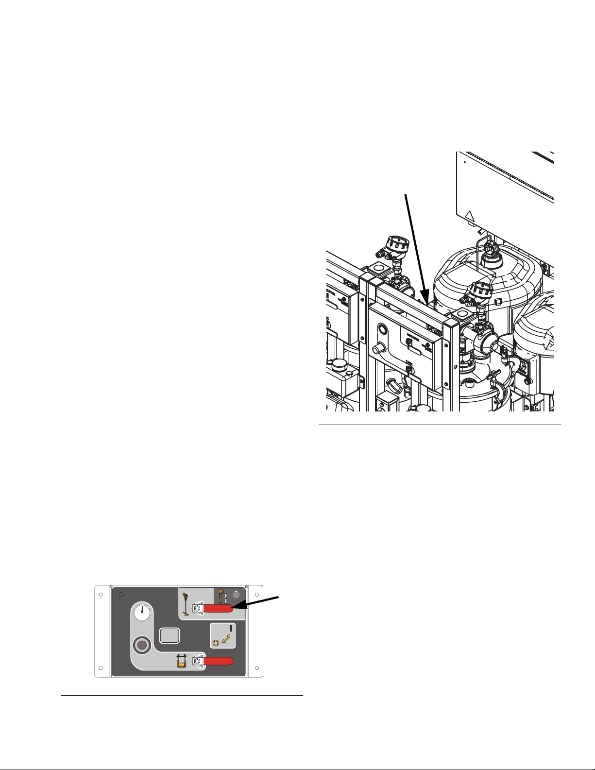
Prime Heated Fluid Circulation System
The heated fluid circulation system includes heated
hoses alongside the material hoses for the length of the
hose bundle, heated fluid circulation through the mix
manifold, and heated fluid circulation through the tank
double-wall which is insulated by a jacket.
Hose Bundle Heating System
1. Add a 50% water, 50% glycol anti-freeze mix to the
small translucent tank located at the bottom right
corner of the front of the sprayer module.
NOTE: Even in warm climates, a water/glycol mix
should be used to keep the circulation system clean and
working properly.
2. With air supply on, adjust the silver knob on top of
the diaphragm pump to start the small black diaphragm pump under the tank. Adjust pump to
approximately 2-3 cycles per second.
3. Continue to add the 50/50 fluid mixture as air is
purged from the fluid lines but make sure the tank is
no more than 1/4 to 1/3 full when cold.
3. Adjust the silver knob located just above the Feed
Module Air Controls. When looking at the Feed
Module Air Controls, the knob will be visible just
above them. See F
IG
. 23. Adjust knob until tank
heated fluid pump reaches approximately 2-3 cycles
per second.
Adjustment Knob Location
ti20126a
NOTE: Re-tighten all heated fluid circulation tube fittings
after the first time the system has been run at full temperature.
Double-Walled Tank Heating System
NOTE: The double-walled tanks are pre-filled with a
water/glycol mix at the factory. If your tanks are already
filled, skip this section.
1. Add a 50% water, 50% glycol anti-freeze mix to the
small translucent tank located between the tank and
feed pump on the feed module.
2. Turn the agitator and tank heated fluid pump air ball
valve ON.
FEED PUMP
BYPASS
ti20127a
F
IG
. 22
FIG. 23
4. Continue to add the 50/50 fluid mixture as air is
purged from the fluid lines but make sure the tank is
no more than 1/4 to 1/3 full when cold.
5. Repeat for other feed module.
NOTE: Re-tighten all heated fluid circulation tube fittings
after the first time the system has been run at full temperature.
3A2776D 23
Page 24
Initial Startup
Initial Startup
Perform this procedure on new systems. Systems are
tested at the factory with mineral oil and there will be
residual oil in the material lines. Flush new systems if A
or B material will not function properly if it contacts mineral oil.
NOTE: If the tank return lines are not disconnected on
the initial priming of the system, all of the oil in the material lines will be pushed back into the tank and mixed
with the material, which will contaminate all of the fluid in
the tank.
1. Verify all procedures in the Setup section beginning
on page 14 have been properly performed.
2. Perform Adjust Packing Nuts on page 52.
3. Turn main power switch (BA) ON and verify the system air inlet ball valve (E) is open. See F
page 10 and F
4.
If your A or B material will not function properly if it
IG
. 1 on page 7.
mixes with a small amount of mineral oil,
IG
. 4 on
perform
the remainder of this Initial Startup procedure once
with grounded pails of solvent instead of A and B
material pails. After performing this entire procedure
once with solvent, perform it a second time with the
A and B materials. Be sure to choose a solvent that
is compatible with your material and with the wetted
parts in this system. See Technical Data on
page 85.
5. Close both feed system air controls ball valves then
open the brass valve on the tank lid air assembly.
Air pressure gauge should read 0 psi. Close the
brass valve.
FEED PUMP
BYPASS
Return line
port
ti20267a
FIG. 25
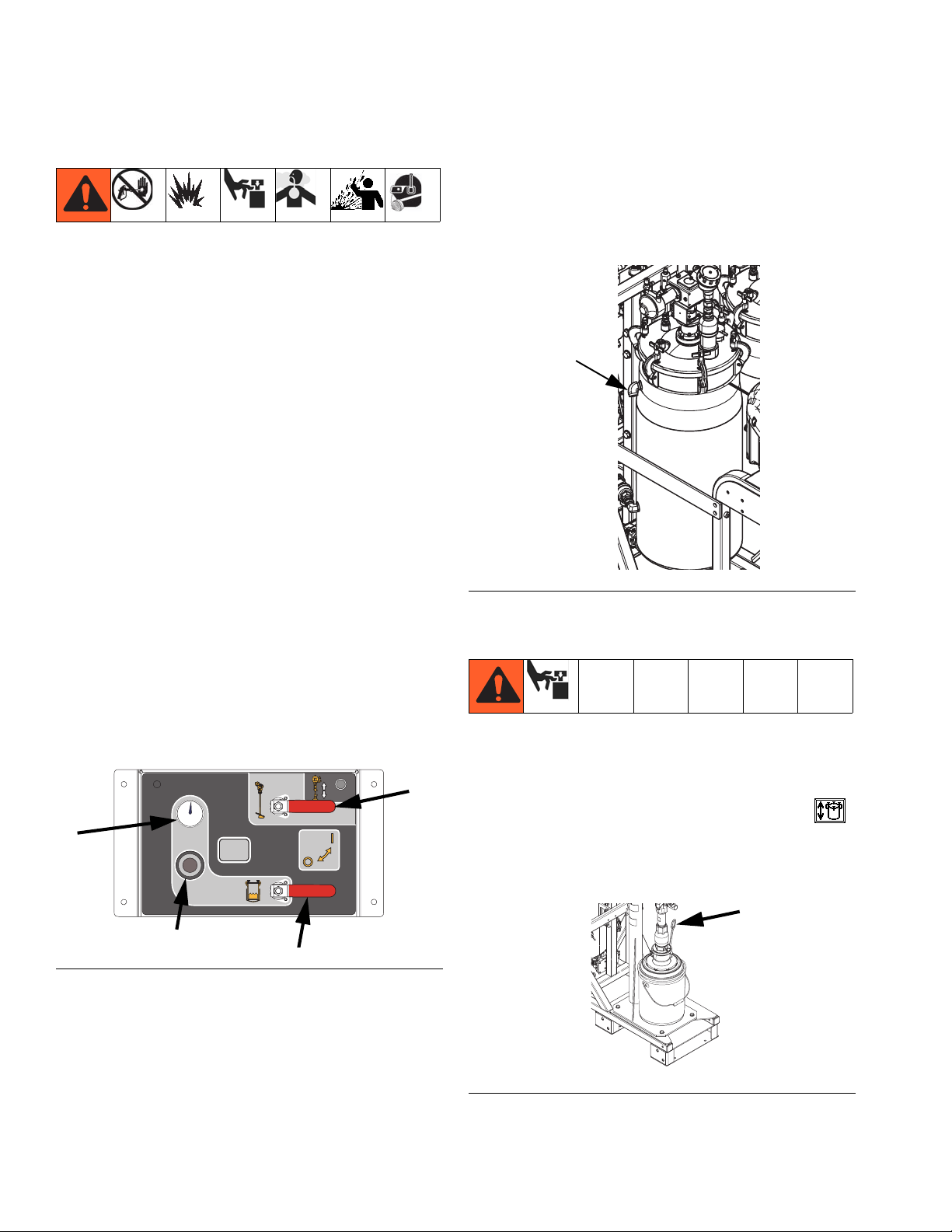
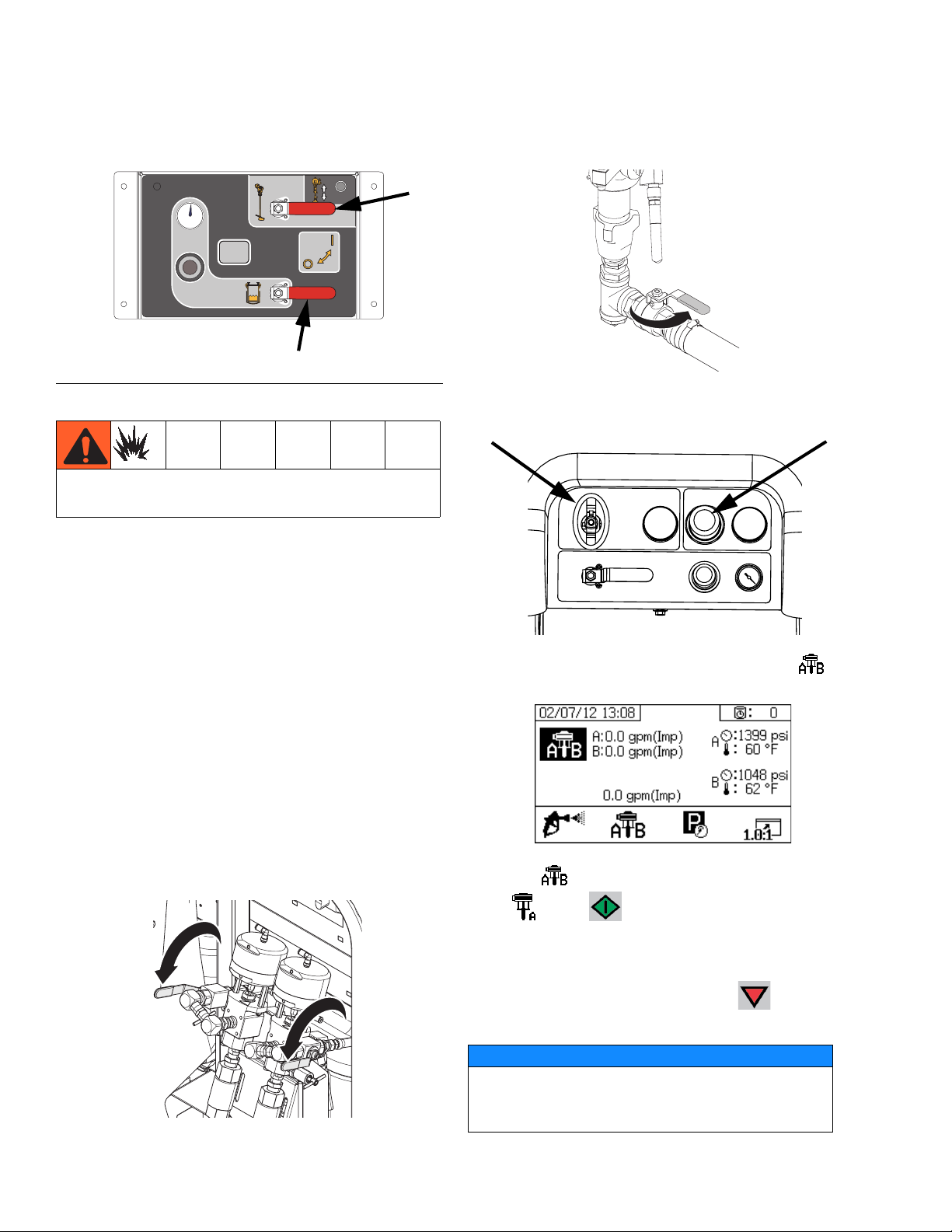
7. Fill the tanks with material:
NOTE: If adding flush solvent, remove the platen from
the feed pump by loosening the two setscrews and the
air tube. Drop the feed pump directly into the pail.
a. Navigate to the Supply screen then press
to activate automatic tank filling. See page 73.
b. Remove the priming stick from the platen.
ti20127a
FIG. 24
6. Disconnect the material circulation return line from
the side of each tank then cap the tank port. This
enables pushing the mineral oil out of the fluid lines.
Route the return lines into waste containers. See
F
IG
. 25.
ti20108a
FIG. 26
24 3A2776D
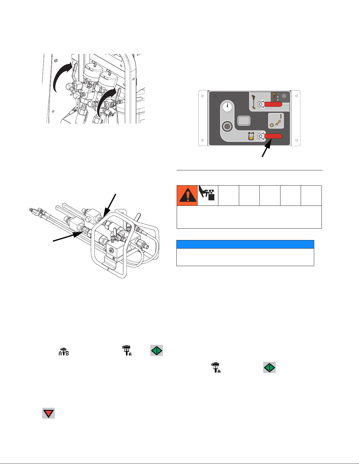
Page 25
Initial Startup
c. Slide main air slider valve (DA) and air motor
slider valve (DF) to the OFF position. See F
27.
DF
DD
DA
F
IG
. 27: Feed Pump Controls
ti20104a
DE
DC
DB
d. Back out the air regulator (DB) then lift the RAM
director valve (DC).
e. Slide main air slider valve (DA) ON.
f. Slowly adjust the air regulator (DB) to increase
air pressure until the RAM begins to lift. Use air
regulator to adjust RAM speed.
g. Adjust director valve to the neutral position
when the platen is high enough to position the
pail beneath the platen.
h. Install pail of material beneath feed pump
platen.
IG
k. Ensure platen is centered on pail when it con-
.
tacts it. Repeat previous steps until platen is
centered on pail.
l. Adjust air regulator (CB) to increase air pres-
sure until the RAM presses into the pail. Install
priming stick once fluid begins exiting the priming stick hole.
NOTE: New platens components may be stiff and resist
entering the pail. Continue increasing pressure up to 80
psi until platen enters the pail. If it does not enter at 80
psi, the thick clear packing on the platen may need to be
flipped upside down so the wider diameter side is up
and the smaller diameter side is down.
Use the minimum pressure possible to lift the platen
out of the pail to minimize material splattering when
the platen exits the pail.
m. With the platen pressing into the fluid, slide the
air motor slider valve (DF) to the ON position.
See F
IG
. 27. Feed pump will start cycling. Continue pumping until pail is empty or desired
amount of fluid has been added to the tank.
Slide the air motor slider valve (DF) to the OFF
position to stop the feed pump.
n. To lift the platen out of the pail, press the
blowoff button (DD) then lift the director valve.
The feed pump will push pressurized air into the
pail to remove it from the platen. Do not let the
pail lift off of the frame. If it does, lower the
platen then retry.
o. Repeat the previous steps as necessary until
both tanks are filled to desired level. Do not
overfill the tank.
ti20108a
IG
. 28
F
i. Back out the air regulator (DB) then lower the
RAM director valve (DC).
j. Slowly adjust the air regulator (DB) to increase
air pressure until the RAM begins to lower. Use
air regulator to adjust RAM speed.
3A2776D 25
Page 26
Initial Startup
8. Open both ball valves on the feed module air controls.
FEED PUMP
BYPASS
ti20127a
F
IG
. 29
To reduce the risk of explosion, never turn on heaters
when solvent is in the system.
9. If not already set, adjust the feed module settings:
11. Verify the sampling valves are closed.
12. Open metering pump inlet ball valves.
WLD
13. Turn on air supply and set metering pump air regulator to 20 psi (138 kPa 1.38 bar).
a. Use regulator on the feed module air controls to
set tank air pressure to 60 psi.
b. Adjust silver knob on agitator until it reaches
30 rpm.
c. Adjust silver knob on tank heated fluid circula-
tion pump until it reaches 60 cpm.
d.
If there is no solvent in the tanks,
adjust tank
water heater knob until the 4 is at the 12 o’clock
position then check temperature when the
heater indicator light turns off. Adjust setting
then repeat until desired temperature is
achieved.
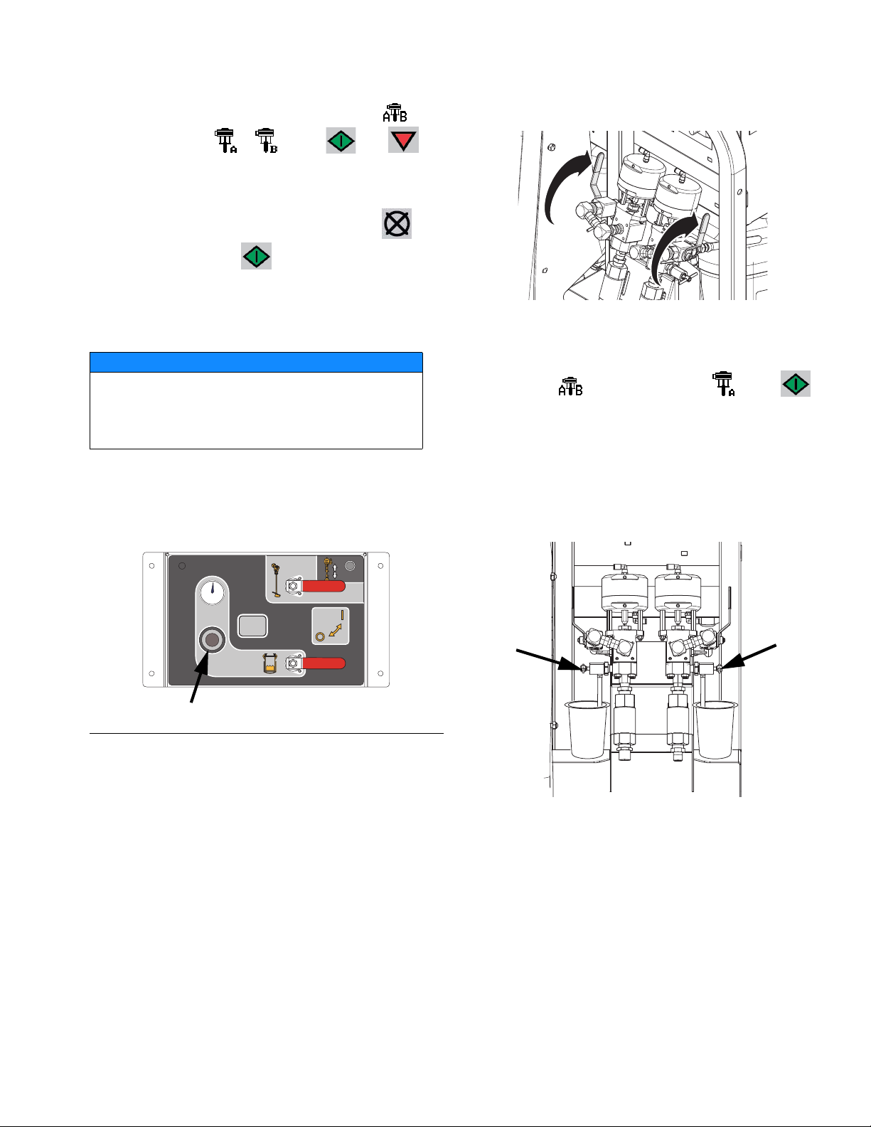
10. Open the circulation valves.
14. At the main run (fluid control) screen, press to
enter manual pump run mode.
15. Press repeatedly to select Metering Pump
A . Press . Slowly turn metering pump air
regulator (CD) clockwise to increase air pressure
until metering pump A starts. Continue to run pump
slowly and dispense into pail until clean material
comes out of the return line. Press to stop
pump. Back out the metering pump air regulator.
NOTICE
Run metering pump as slowly as possible until it is
fully primed to prevent pump damage due to pump
WLD
26 3A2776D
cavitation.
Page 27
Initial Startup
NOTE: To run each side independently, press
repeatedly to set to
or
. Press and as
needed to prime. Monitor containers to avoid overflow.
NOTE: When priming or flushing pumps, it is normal to
get cavitation or pump runaway alarms. Press to
clear alarms then press again as necessary.
These alarms prevent excessive pump speeds, which
will damage pump packings.
16. Repeat the previous step for the B side.
NOTICE
Prior to performing the following step, make sure
the tank is not more than half full. When the tank
pressure is relieved, the fluid will expand, and could
overfill the tank if there is too much in the tank.
17. Back out the tank air pressure regulator on the feed
system air controls and open the brass valve on the
tank lid.
20. Close the circulation valves.
WLD
21. Prime the A sampling valve:
a. Press repeatedly to set to
.
Press .
Slowly turn metering pump air regulator (CD)
clockwise to increase air pressure until metering
pump A starts.
b. With a waste container beneath the valve, open
the A sampling valve slowly until clean material
dispenses then close the sampling valve.
FEED PUMP
BYPASS
ti20127a
F
IG
. 30
18. With the tank air pressure relieved, remove tank
port plugs and reconnect the tank return lines.
19. Adjust the tank air pressure regulator back to the
desired pressure.
ti20109a
22. Repeat the previous step to prime the B sampling
valve.
3A2776D 27
Page 28
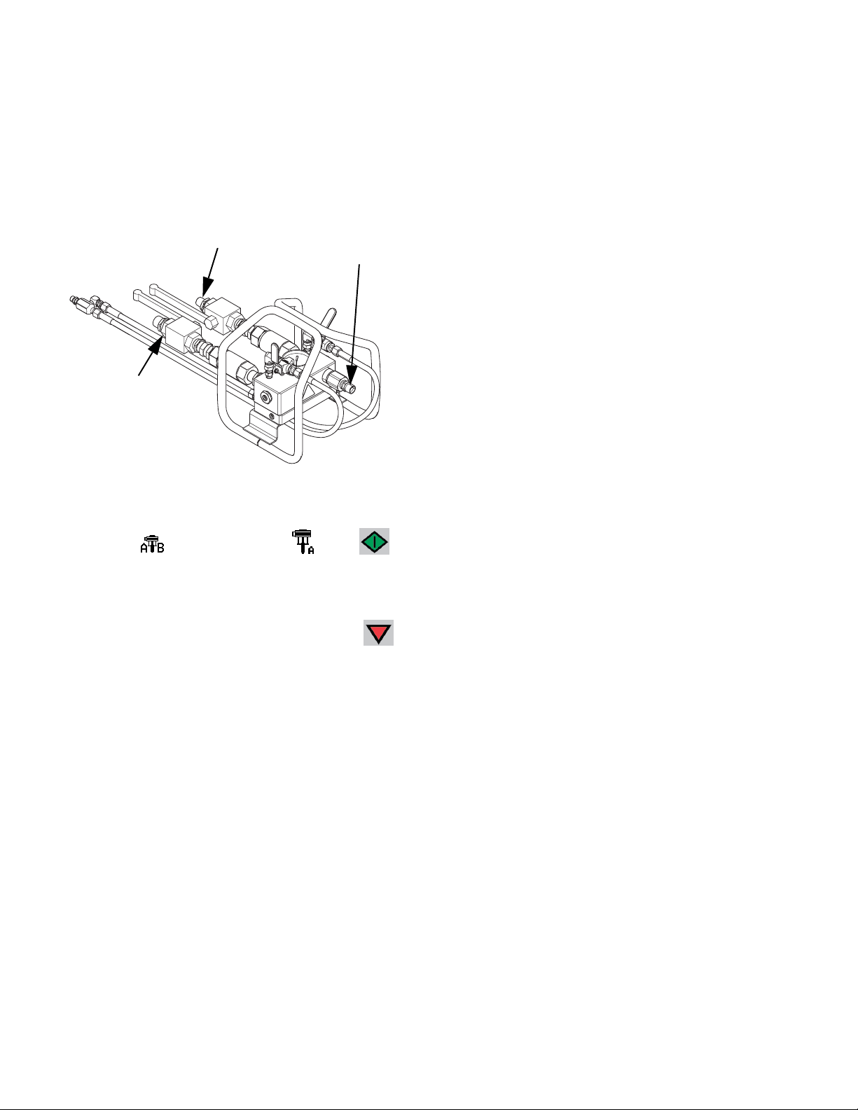
Initial Startup
23. Prime the A material hose:
a. Remove the outlet fitting from the mix manifold
so materials can be dispensed without mixing.
b. Place a waste pail under the mix manifold out-
let.
B Valve
A Valve
ti20088a
Outlet
Fitting
c. Open the A side mix manifold inlet ball valve.
d. Press repeatedly to set to
.
Press .
Slowly turn metering pump air regulator (CD)
clockwise to increase air pressure until metering
pump A starts. Continue until clean material dis-
penses from the A material line then press
to stop pump.
e. Close the A side mix manifold inlet ball valve
then reconnect to the mix manifold. Back out
the metering pump air regulator.
f. Repeat for the B material line.
NOTE: Now all of the material lines are primed except
for the section from the mix manifold to the gun.
24. Perform the Prime Solvent Flush Pump procedure
on page 29 to flush out the oil from those lines, and
to finish preparing for spraying.
28 3A2776D
Page 29

Prime Solvent Flush Pump
• The equipment must be grounded to reduce the
risk of static sparking and electric shock. Hold gun
firmly to side of grounded pail when triggering into
pail.
• Do not point gun at anyone or at any part of the
body.
• Solvent can irritate eyes, nose, throat, and skin.
Hot fluid and parts can burn skin. Wear appropriate protective wear when using flush solvents
and/or if fluid temperature exceeds 110° F (43° C).
• Keep clear of moving parts.
1. Turn main power switch ON and verify the XM PFP
air supply ball valve is open.
2. Fill grounded metal pail with solvent.
3. With the mix manifold inlet ball valves and the mix
manifold solvent flush ball valves closed, trigger the
gun into a grounded pail to remove any residual
pressure.
4. Ensure trigger lock is engaged. Remove spray tip.
Prime Solvent Flush Pump
7. Open the solvent flush valves.
ti20110a
8. Disengage trigger lock and trigger gun into a
grounded pail. Press gun against the grounded pail.
Use a pail lid with a hole to dispense through. Seal
around hole and gun with a rag to prevent splash
back.
9. Open solvent pump air valve (CB). Pull out and
slowly turn solvent pump air regulator (CG) clockwise until solvent pump begins to slowly cycle.
CG
CB
10. Continue to dispense until all air is purged.
TI19265a2
5.
If the optional hot water flush kit is not used,
TI19266a
place
solvent flush pump siphon tube in the pail of solvent.
TI1953a
11.
If the optional hot water flush kit is used,
perform the
following steps:
NOTICE
6.
If the optional hot water flush kit is used,
water hose connected to the water inlet. Do not turn
on the water heater yet.
3A2776D 29
turn on the
To avoid burning out the heater element in the
water heater, never turn on the water heater
unless it is filled with water.
Page 30

Prime Solvent Flush Pump
a. After water begins dispensing from the gun, turn
the water heater toggle switch located on the
back of the heater ON.
b. Turn the water heater power switch on the sys-
tem junction box ON.
ti20101a
NOTE: The water heater must be filled with fluid and
turned on at least 45 minutes prior to when flushing will
be required.
12. Close solvent pump air valve (CB) to stop pump
then trigger gun into grounded pail to relieve pressure. Engage gun trigger lock.
TI19265a2
13. Close the solvent flush ball valves on the mix manifold.
30 3A2776D
Page 31

Adjust Ratio and System Settings
Adjust Ratio and System
Settings
1. Turn key to right (setup position). Yellow LED will
flash and the Setup mode Home screen will display.
2. Press and to change the volume ratio setting.
3. When desired ratio is displayed, turn key to left. Yellow LED will turn off.
4. Change all settings in the user-interface to the
desired values. See Appendix A - User Interface
Display on page 58 for detailed screens information, including navigation and instructions.
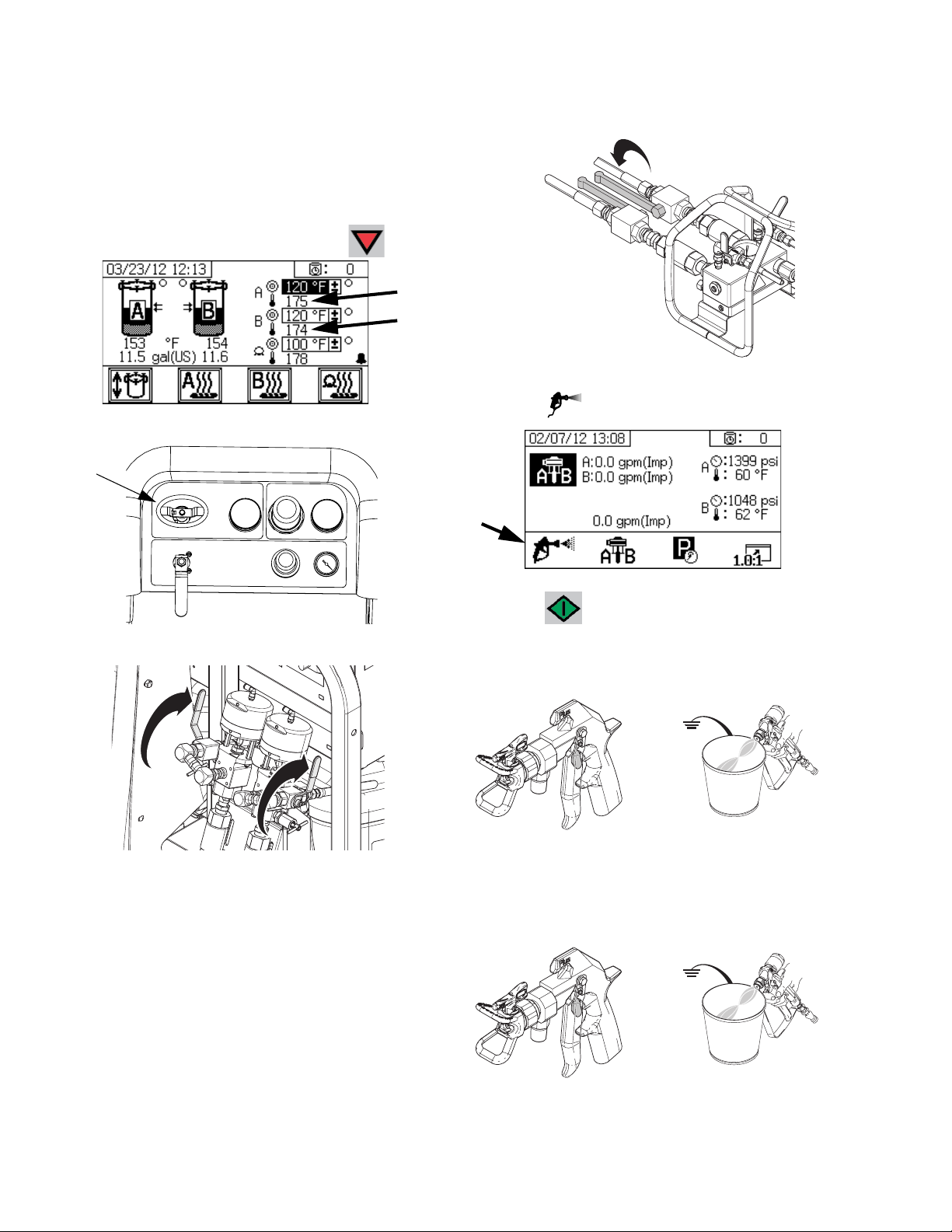
Temperature Settings
2. After the red light goes out, check the temperature
on the gauge and adjust as needed to get desired
temperature.
NOTE: Tank will not heat up faster by increasing the
temperature setting.
A and B Material Temperature
There is one Viscon HF 5400 watt heater for heating
material while in circulation or while dispensing. These
heaters are digitally controlled to your specific setpoint
temperature.
The Supply screen controls and displays the setpoint
and actual temperature.
Set the desired A and B temperature. The box next to
the target is the setpoint. The number next to the thermometer is the actual temperature.
Press and to turn on the A and B primary
heaters.
See Spray procedure for pre-heating procedure to use
prior to spraying.
Set all temperatures per your materials data sheet specifications.
Feed Tanks
Temperature is controlled by an adjustable thermostat
on each tank heater. Power to the tank heaters is supplied from the power switches (BB, BC) next to the main
power switch. Tank material temperature is displayed on
the Supply screen under the tank icon. The circulating
heated fluid temperature is displayed on the temperature gauge next to the heater.
1. Set heater control knob to 4. This is approximately
120°F (49°C).
Hose Bundle Temperature
Set the desired hose bundle temperature on the supply
screen.
Be sure the knob on the Viscon HP hose heater (the
middle of the three heaters on the front of the system) is
turned fully clockwise (full ON position). Always leave in
the full ON position. Heater has a separate digital control module in the junction box.
The heater will heat the water/glycol mixture to 180°F
(82°C) as needed until the hose bundle gets up to the
desired temperature. It will then run at whatever temperature is required to maintain the hose setpoint temperature.
Press to turn the hose bundle heater ON or OFF.
3A2776D 31
Page 32

Spray
Spray
Do not point gun at anyone or at any part of the body.
Solvent can irritate eyes, nose, throat, and skin. Hot
fluid and parts can burn skin. Wear appropriate protective wear when using flush solvents and/or if fluid
temperature exceeds 110° F (43° C).
This procedure includes steps ensure that any settled
fillers are well-mixed with the material, the metering
pump lines are fully primed, the metering pump check
valves are operating smoothly, and materials are up to
temperature prior to spraying the production surface.
When the temperatures displayed on the Supply screen
reach operating temperature, the material is ready to
spray.
After the first day of spraying follow Pressure Relief
Procedure, page 38, then tighten packing nuts on
pumps and dosing valves.
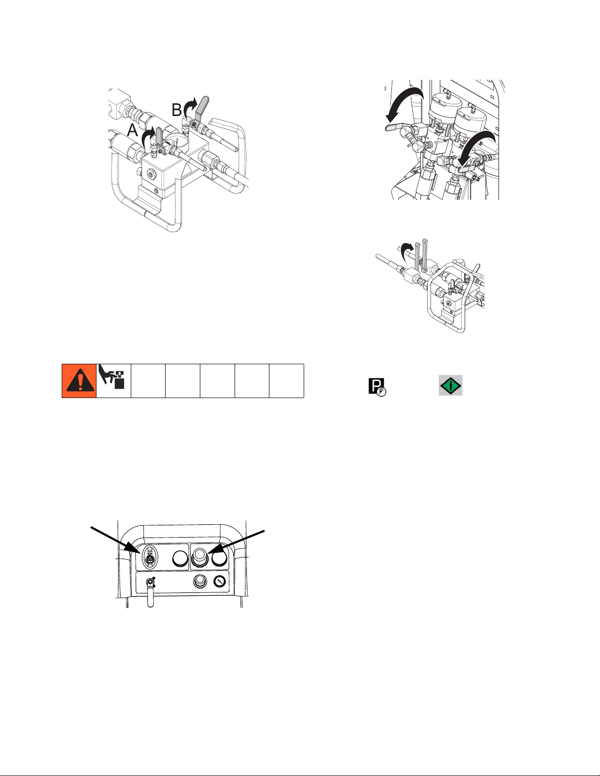
5. Open both ball valves on the feed module air controls.
FEED PUMP
BYPASS
ti20127a
FIG. 31
6. Close mix manifold flush valves.
1. If this is the Initial Startup or if system components
have been replaced, follow the Initial Startup procedure beginning on page 24.
2. Turn main power switch ON and verify the XM PFP
air supply ball valve is open.
3. Perform Prime Solvent Flush Pump, page 29 to
ensure the solvent pump is prepared to quickly flush
out mixed material when done spraying.
NOTE:
If the optional hot water flush kit is used,
the
water heater must be filled with fluid then turned on 45
minutes prior to when flushing will be required.
4. If tank levels are low, fill them with material. See
step 7 on page 24.
ti20095a
7. Close mix manifold ball valves.
ti20129a
32 3A2776D
Page 33

Spray
8. Open recirculation valves.
WLD
9. Ensure metering pump air supply is OFF.
pressure to the metering pumps until the enabled
pump(s) begin running slowly.
CA
13. Turn A and B tank fluid heaters ON.
CD
10. At the main run (fluid control) screen, press to
enter manual pump run mode.
11. Press repeatedly to select . Press to
begin circulating.
NOTICE
Run metering pump as slowly as possible until it is
fully primed to prevent pump damage due to pump
cavitation.
12. Back out the metering pump air regulator (CD) then
turn on the main air shutoff valve (CA). Use metering pump air regulator to slowly increase the air
ti20101a
14. To adjust tank fluid heater temperature, adjust the
numbered knob on the heater.
15. Turn on the primary material heaters.
a. Navigate to the Supply screen. See Operator
Command Mode Screens on page 66.
b. Press and to turn on the A and B pri-
mary heaters, and press to turn on the
hose bundle heater.
16. If desired, press to enable automatic tank filling. See page 73 for automatic tank filling details.
17. Run the metering pumps until the material has
reached the desired temperature.
NOTE: If you circulate the A side metering pump at
pressures greater than 3000 psi (21 MPa, 210 bar), an
advisory is issued and the yellow LED on the display
illuminates. This is a reminder to select Spray mode
prior to spraying and to circulate at a lower pressure to
avoid excessive pump wear.
3A2776D 33
Page 34
Spray
NOTE: If you circulate the A side metering pump above
5200 psi (35.4 MPa, 354 bar), an alarm shuts down the
pump to prevent accidentally spraying material while still
in circulation mode.
18. Once the materials reach the desired temperature
as shown on the supply screen, press .
19. Turn off the main air shutoff valve (CA).
CA
24. Open mix manifold ball valves.
ti20128a
25. Select .
20. Close recirculation valves.
WLD
21. Perform Pump and Metering Test on page 40.
22. Perform Ratio Test (Batch Dispense or Ratio
Test) on page 42.
23. Perform Down Stream Valve Leak Test on
page 43.
26. Press to start the metering pumps.
27. Disengage trigger lock and trigger gun into a
grounded metal pail. Use a metal pail lid with a hole
to dispense through to avoid splashing.
TI19265a1
TI1953a
28. Adjust metering pump air regulator (CD) to 30 psi
(0.21 MPa, 2.1 bar).
29. Dispense until clean, well-mixed epoxy flows from
the gun.
TI19265a1
TI1953a
30. Engage trigger lock.
34 3A2776D
Page 35

31. Perform the Mix and Integration Tests on page 44.
When necessary, engage trigger lock then install
the tip on gun.
Spray
2
TI19265a2
1
NOTE: While spraying, it is best to continuously hold the
trigger. Do not release the trigger unless necessary.
This maximizes the material temperature consistency
and minimizes fiber buildup.
32. Adjust air regulator (CD) to the necessary spraying
pressure and trigger gun to spray material on a test
panel. Look at ratio screen to ensure it is reading
the correct ratio. Continue spraying on the test
panel until the desired pattern results then begin
spraying the production surface.
33. Follow Flush Mixed Material on page 36 when you
are finished spraying if the potlife of the mixed materials in the system could expire before you spray
again.
NOTE: Pot life of the mixed materials in the system is
much shorter than the dry time of dispensed epoxy
because mixed material potlife or working time
decreases with increased temperature.
3A2776D 35
Page 36

Flush Mixed Material
Flush Mixed Material
• The equipment must be grounded to reduce the
risk of static sparking and electric shock. Hold gun
firmly to side of grounded pail when triggering into
pail.
• Do not point gun at anyone or at any part of the
body.
• Solvent can irritate eyes, nose, throat, and skin.
Hot fluid and parts can burn skin. Wear appropriate protective wear when using flush solvents
and/or if fluid temperature exceeds 110° F (43° C).
• Keep clear of moving parts.
This procedure flushes out mixed material from system
to prevent it from curing in the system.
NOTE: Pot life of the mixed materials in the system is
much shorter than the dry time of dispensed epoxy
because mixed material potlife or working time
decreases with increased temperature.
7. Disengage trigger lock and trigger gun into a
grounded pail. Use a pail lid with a hole to dispense
through. Seal around hole and gun with a rag to prevent splash back.
8. Open solvent pump air supply valve. Pull out and
slowly turn solvent pump air regulator clockwise to
increase air pressure. Use lowest pressure needed
to flush material out of hose.
9. Continue dispensing until clean flushing fluid is dispensed.
Follow this procedure when you are finished spraying if
the potlife of the mixed materials in the system could
expire before you spray again.
1. If necessary, Prime Solvent Flush Pump, page 29.
2. Press to stop the metering pumps.
3. Trigger gun into a waste container to relieve pressure then engage trigger lock.
4. Remove spray tip.
5. Close mix manifold ball valves.
ti20129a
TI19265a1
TI1953a
10. Close the open solvent flush valve. Open the other
solvent flush valve. Continue dispensing long
enough for any remaining mixed material
11. Close solvent pump air supply valve.
12. Trigger gun to relieve pressure in solvent lines then
engage trigger lock.
TI19265a2
6. Open one of the solvent flush valves on the mix
manifold.
36 3A2776D
Page 37
Park Metering Pump Rods
13. Close solvent flush valves.
ti20095a
ti20095a
14. Use a rag and solvent to clean spray tip then reinstall on gun.
15. Remove the static mixer. Clean the mix element
then re-install the mixer.
Park Metering Pump Rods
2. Open fluid recirculation valves.
WLD
3. Close mix manifold material ball valves.
ti20129a
4. Open the metering pump air supply ball valve.
NOTE: This procedure is only necessary when the system will not be used for more than a few hours. The primary purpose of this procedure is to prevent material
from hardening on the metering pump shaft by extending the pump so the portion of the shaft that is exposed
to material is not exposed to the air.
1. Close metering pump air supply ball valve then back
out the air pressure regulator.
5. Press then press to start metering
pumps. Slowly adjust air pressure regulator until
pumps begin to move. Each metering pump will circulate materials until they reach the bottom of the
stroke then will stop.
3A2776D 37
Page 38
Pressure Relief Procedure
Pressure Relief Procedure
Follow the Pressure Relief Procedure whenever
you see this symbol.
This equipment stays pressurized until pressure is
manually relieved. To help prevent serious injury
from pressurized fluid, such as skin injection,
splashing fluid and moving parts, follow the Pressure
Relief Procedure when you stop spraying and before
cleaning, checking, or servicing the equipment.
1. Engage trigger lock.
TI19265a2
2.
If the system will be shut down for more than a few
hours,
perform Park Metering Pump Rods proce-
dure on page 37 to prevent fluid hardening on the
metering pump shafts.
NOTICE
The material may expand when air pressure is
removed. This can cause the tank to overfill and
damage the parts attached to the tank lid. To prevent overfilling the tank, never relieve air pressure
in the tank unless the tank is less than half full.
Verify tank material level on the user interface, see
Appendix A - User Interface Display section
beginning on page 58.
5.
If necessary to relieve tank air pressure:
close both
feed system air control ball valves and back out the
air pressure regulator. Open the brass valves on the
tank lids for full tank de-pressurization. Pressure
gauge should read 0 psi.
FEED PUMP
BYPASS
ti20127a
3. Press .
4. Slide the feed pump air supply valve (DF) and director valve air supply valve (DA) to the OFF position.
DF
DD
DA
F
IG
. 32: Feed Pump Air Controls
ti20104a
DE
DC
DB
F
IG
. 33
6. Open mix manifold ball valves.
ti20128a
38 3A2776D
Page 39

Pressure Relief Procedure
7. Open recirculation ball valves.
WLD
8. Disengage trigger lock.
TI19265a1
9. Hold a metal part of the gun firmly to a grounded
metal pail. Trigger gun to relieve pressure in material hoses. Use a pail lid with a hole to dispense
through. Seal around hole and gun with a rag to prevent splash back.
11. Close mix manifold material ball valves.
ti20129a
12. Perform Flush Mixed Material procedure beginning
on page 36 to prevent mixed material curing in the
system and to relieve pressure in the solvent lines.
13.
If the system will be shutdown for more than a few
hours,
fill metering pump A and B packing nuts with
throat seal liquid (TSL).
NOTE: Fluid pressure in the system is now relieved.
10. Engage trigger lock.
TI1953a
TI19265a2
3A2776D 39
Page 40

System Verification
System Verification
NOTE: Each sampling valve must be primed prior to
beginning this procedure to ensure best accuracy. If the
clear tube connected to the sampling valve is not filled
with material, prime the sampling valves.
Graco recommends running the following tests daily
prior to spraying on the production surface.
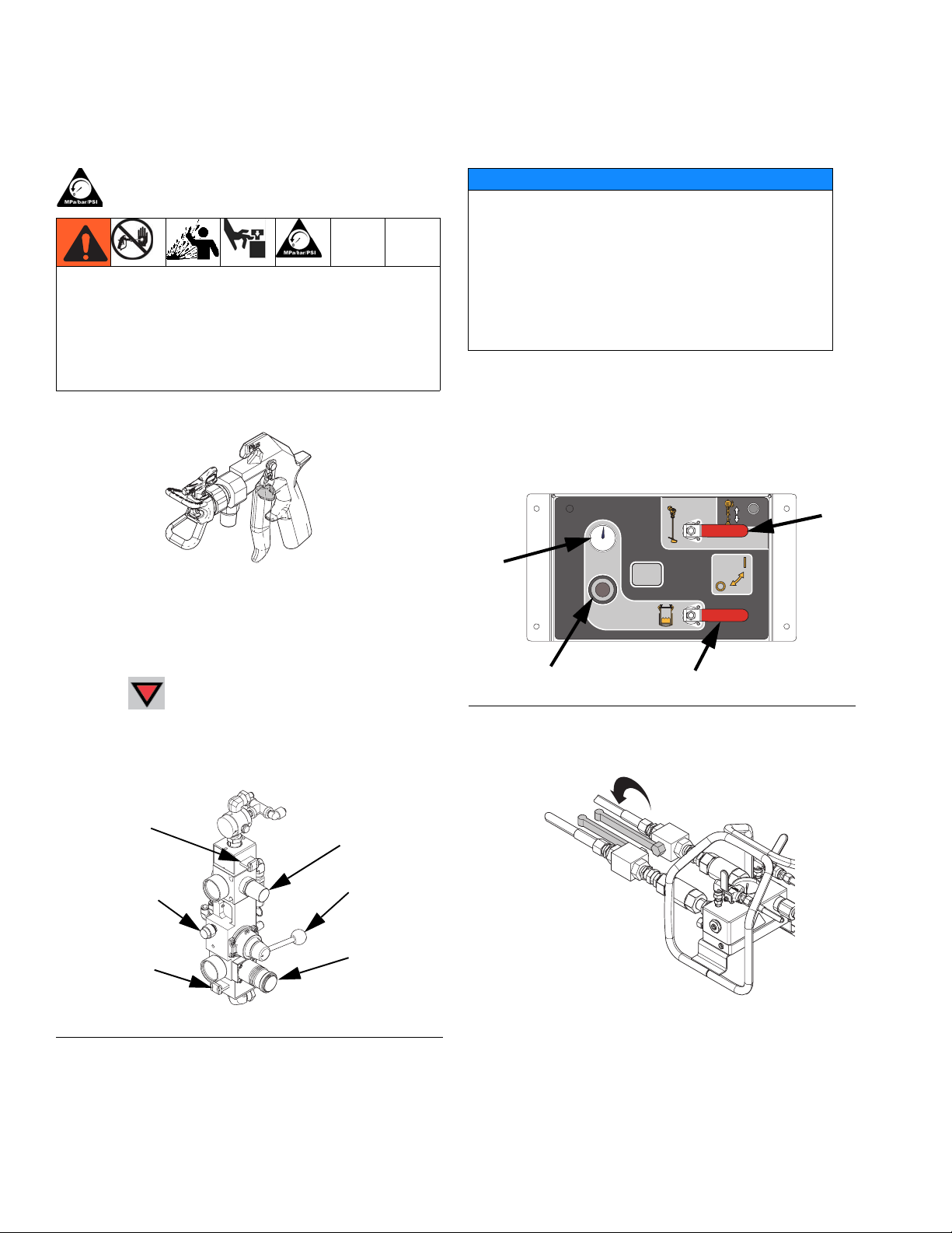
Pump and Metering Test
This test checks the following five items and should be
run every time a new job is started, or if there is a suspected problem.
• Verifies that the metering pumps installed match the
metering pumps selected on the Setup screen by
dispensing exactly 750 ml of each material.
• Verifies that each metering pump holds fluid against
the metering pump inlet valve by stalling on the
down stroke.
• Verifies that each metering pump holds fluid against
the metering pump piston valve and packings by
stalling on the upstroke.
• Verifies that each metering valve holds fluid and that
there are no external leaks between the metering
pump and metering valve.
• Verifies that the recirculation valves (AC, AD) are
closed and do not leak.
This test will dispense 750 ml of component A, and then
750 ml of component B. Dispense into separate cups so
the fluid can be returned to the supply tanks.
1. Verify the clear tube connected to each sampling
valve is filled with material. If not, perform the following steps to ensure accuracy of the metering test.
a. Turn metering pump air supply valve on.
b. At the main run (fluid control) screen, press
to enter manual pump run mode.
c. Press repeatedly to select . Press
.
d. With a waste container beneath the sampling
valve, slowly open the valve until material
begins to slowly dispense. Once clean material
dispenses from the sampling valve, and the
clear tube is completely filled with clean mate-
rial, press to stop dispensing. Repeat with
the other side if necessary.
NOTE: During each dispense the flow will stop once to
stall the upstroke, once to stall the downstroke, and then
it will finish the dispense. Do not close the sampling
valve until the fluid flow stops and the blue metering
pump light (DK) goes out.
NOTE: Material hoses from the system to the mix manifold must be filled with material and pressurized for testing to be successful.
40 3A2776D
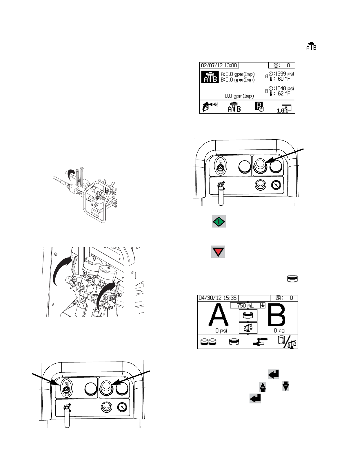
2. Enter Test mode in the run (fluid control) screen.
See Test Screens on page 69. Select
run pump test.
to
Page 41

System Verification
3. Set metering pump air regulator (CD) pressure to
zero. Open metering pump air valve (CA). Adjust
metering pump air regulator (CD) pressure to 50 psi
(0.35 MPa, 3.5 bar).
CA
4. Dispense fluid A:
a. Close recirculation valves, mix manifold inlet
ball valves, and sampling valves.
b. Place a clean 1 quart (1000 cc) container under
sampling valve A.
5. Dispense fluid B as follows:
a. Place a clean 1 quart (1000 cc) container under
sampling valve B.
CD
ti20112a
b. Slowly open and adjust sampling valve B to
achieve desired flow. Metering pump stops
automatically; twice during test and again when
dispense completes. Metering pump B
light (DK) turns off.
ti20111a
c. Press . Metering pump A light (DK) comes
on.
d. Slowly open sampling valve A until material
begins to dispense. Metering pump stops automatically; twice during test and again when dispense completes. Metering pump A light (DK)
turns off, metering pump B light (DK) turns on.
e. Close sampling valve A (AE).
c. Close sampling valve B.
6. Compare fluid amounts in containers; they should
each equal 750 ml (25.3 fl. oz.). Repeat test if fluids
are not equal. If problem persists, see Alarm Code
Troubleshooting, page 79.
7. Return fluid used in test to corresponding fluid supply container.
Confirm Pump and Metering Test
The Confirm Pump and Metering Test screen displays
when the pump and metering test completes without
error. This screen displays the target weight of material
dispensed into each beaker from each metering pump.
To have your test results entered in the downloadable
USB log files, enter the two weights.
3A2776D 41
Page 42
System Verification
Batch Dispense or Ratio Test
NOTE: This test dispenses a calculated volume of each
fluid based on ratio. The two fluids combined equal the
batch size selected.
Follow this procedure to dispense a batch (into one container) for touch-up work or to verify the dispensed ratio
(use separate containers for fluids A and B).
When checking the ratio, use a scale to tare the two
containers then weight the dispensed materials.
1. Close mix manifold material ball valves.
e. At the main run (fluid control) screen, press
to enter manual pump run mode.
f. Adjust metering pump air regulator pressure to
50 psi (0.35 MPa, 3.5 bar).
ti20129a
2. Close recirculation ball valves.
WLD
3. Pressurize the material lines:
d. Set metering pump air regulator pressure to
zero. Open metering pump air valve.
g. Press .
h. When both the A and B metering pumps stall,
press .
4. Enter Test mode in the run (fluid control) screen.
See Test Screens on page 69. Select
to run
batch dispense test.
5. Adjust dispense amounts from 500 ml to 2000 ml (in
250 ml increments) by pressing to open the
drop-down box. Then press and to select
the desired value. Press to select that value.
6. Close recirculation valves, mix manifold inlet ball
valves, and sampling valves.
42 3A2776D
Page 43

System Verification
7. Place a clean container under sampling valve A.
ti20111a
8. Press . Metering pump A light comes on.
9. Dispense fluid A. Slowly open and adjust sampling
valve A (AE) to achieve desired flow. The metering
pump stops automatically when dispense completes
and metering pump A light (DK) turns off and metering pump B light (DK) turns on.
Batch dispense:
12.
Ratio check
als dispensed.
stir material until mixed.
: compare net weight of A and B materi-
Confirm Batch Dispense Test
The Confirm Batch Dispense Test screen displays when
the batch dispense test completes without error. This
screen displays the selected ratio between the metering
pumps and the weight of material dispensed from each
metering pump.
The gray at the bottom of the beaker represents the volume of material dispensed by metering pump A and the
black at the top of the beaker represents the volume of
material dispensed by pump B.
Enter the weight of each sample in the A and B input
boxes. The system will calculate the ratio and display a
check in the box if it is within tolerance. The result of the
test is also entered in the USB log.
10. Close sampling valve A (AE).
11. Dispense fluid B as follows:
a.
Batch dispense:
pling valve B (AF).
Ratio check
pling valve B (AF).
b. Slowly open and adjust sampling valve B (AF)
to achieve desired flow. The metering pump
stops automatically when dispense completes.
Metering pump B light (DK) turns off.
move container under sam-
: place clean container under sam-
ti20112a
Down Stream Valve Leak Test
This test confirms or troubleshoots leaks in components
located down stream of the dosing valves. Use this test
to detect closed or worn valves, and to detect leaks in
circulation valves installed at a remote mix manifold.
1. Close both mix manifold valves downstream of the
dosing valves.
2. Close recirculation valves (AC, AD).
c. Close sampling valve B (AF).
3A2776D 43
Page 44

System Verification
3. Enter Test mode in the run (fluid control) screen.
See Test Screens on page 69. Select
run down stream valve leak test.
4. Select
(AA, AB) are open by verifying blue LEDs are illumi-
nated for both dosing valves.
5. If test is successful, both metering pumps will stall
against the downstream valves when the dosing
valves (AA, AB) are open. If any movement is
detected in the metering pumps after stalling, an
alarm is issued indicating which side has a leak.
.
Press . Ensure dosing valves
to
Mix and Integration Tests
Use the following tests to check for proper mix and integration.
Butterfly Test
At low pressure, normal flow rate, and without a spray
tip installed, dispense a 1/2 in. (12.7 mm) bead of material onto foil until multiple changeovers of each metering
pump have occurred. Fold the sheet of foil over the fluid
then peel it back and look for unmixed material (appears
marble-like).
Curing Test
Spray a single continuous pattern on foil at typical pressure setting, flow rate, and tip size until multiple changeovers of each metering pump have occurred. Trigger
and de-trigger at typical intervals for the application. Do
not overlap or cross over your spray pattern.
Check curing at various time intervals, listed on the
material data sheet. For example, check for dry to touch
by running your finger along the test pattern’s entire
length at the time listed on the data sheet.
NOTE:
Spots that take longer to cure indicate insufficient integration.
Appearance Test
Spray material onto metal substrate. Look for variations
in color, gloss, or texture that may indicate improperly
catalyzed material.
44 3A2776D
Page 45
Empty and Flush Entire System
a. With director valve (DC) in the neutral position
• Running solvent through heaters can cause a fire
or explosion. Turn off heaters and allow to cool
before flushing. Do not turn on heaters until fluid
lines are clear of solvent.
• Splashing fluid can land on exposed body parts
and irritate the skin. Cover fluid container and use
the lowest possible pressure when flushing to
avoid splashing.
Empty and Flush Entire System
and the RAM air regulator (DB) backed out,
slide main air slider valve (DA) ON.
DF
DD
DE
DC
Only perform this procedure when:
• The system will not be used for more than one
month.
• Changing to a new material in the A or B side.
To flush a new system, see Initial Startup on page 24.
To flush only the mix manifold to the gun, see Flush
Mixed Material, page 36.
NOTE: While hot water is sometimes used to flush
mixed material from the system, it is not recommended
for flushing the entire system. When flushing the entire
system, use a solvent the dissolves the material.
This procedure is designed to minimize the volume of
discarded A and B material when emptying and flushing
the entire system.
1. Flush Mixed Material, page 36.
2.
If applicable,
remove the feed pump from pail:
DA
ti20104a
DB
FIG. 34: Feed Pump Air Controls
b. Lift the director valve to the UP position, the
press and hold the blowoff button (DD) while
increasing the air pressure using the RAM air
regulator. When the feed pump exits the pail,
move the director valve to the neutral position
and release the blowoff button.
3. Empty the feed pump outlet material lines to the
tank:
a. Slide the air motor slider valve (DF) ON.
b. Rotate air motor regulator (DE) to increase air
pressure until feed pump begins to cycle. Continue until all material from outlet line to the tank
have been pushed into the tank. This will be
noticeable by an increase in feed pump cycle
rate.
4. Make sure all heaters are off and cool.
3A2776D 45
Page 46
Empty and Flush Entire System
5. Close the circulation valves.
WLD
6. Empty the A material tank:
a. Close the A side mix manifold inlet ball valve.
b. Disconnect the A material hose from the mix
manifold at the fitting between the ball valve and
check valve.
f. Close the A side mix manifold inlet ball valve.
g. Close the tank air supply ball valve then open
the brass valve on the top of the tank to relieve
tank air pressure.
FEED PUMP
BYPASS
ti20127a
FIG. 35
The tank lid assembly is heavy. To prevent crushing
your fingers if the tank lid is accidentally dropped,
exercise caution while lifting the tank lid.
ti20088a
c. Place the A material hose in a clean container
to salvage the dispensed material. Make sure to
have enough clean containers within reach to
switch to as each container is filled.
d. Open the A side mix manifold inlet ball valve.
e. Press repeatedly to set to
.
Press .
Slowly turn metering pump air regulator (CD)
clockwise to increase air pressure until metering
pump A starts. Continue pumping until the
metering pump speed increases on its own
which signals that the tank is now empty and
there is air at the metering pump inlet. Press
to stop metering pump then back out the
air pressure regulator.
NOTICE
The level sensor is very sensitive. Be careful not to
damage it while lifting the tank lid.
h. Remove the tank lid assembly.
i. Scrape remaining material from the walls of the
tank into the tank outlet.
j. Re-install the tank lid assembly.
k. Close the brass valve on the top of the tank
then open the tank air supply ball valves to
pressurize the tank.
l. With selected, press . Slowly turn
metering pump air regulator (CD) clockwise to
increase air pressure until metering pump A
starts. Wait until the metering pump speed
decreases, meaning that it is now primed with
the new material from the tank inlet. Continue
pumping until the metering pump speed
increases, which means all of the material has
46 3A2776D
Page 47
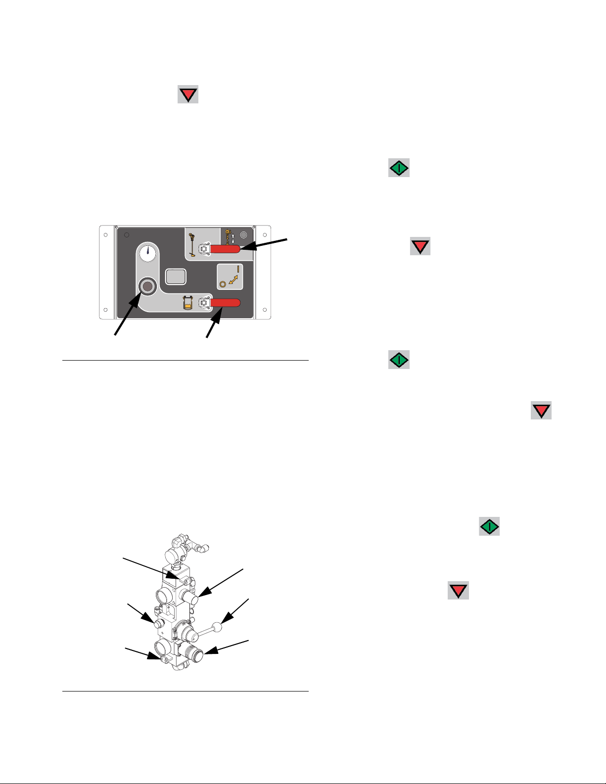
Empty and Flush Entire System
been pumped and there is air at the metering
pump inlet. Press to stop metering pump
then back out the air pressure regulator.
7. Add solvent to the A material tank:
a. On the A side feed module, close both feed sys-
tem air control ball valves and back out the air
pressure regulator. Open the brass valve on the
top of the tank to fully relieve tank air pressure.
FEED PUMP
BYPASS
ti20127a
F
IG
. 36
b. Remove the platen from the A side feed pump
by loosening the two setscrews and the air tube.
c. Place a pail of solvent under the feed pump
then slowly insert feed pump into the pail. The
feed pump should rest on the bottom of the pail.
d. Slide the air motor slider valve (DF) to ON.
Adjust the air regulator (DE) so the feed pump
runs very slowly.
e. Continue adding solvent to tank until enough
solvent is in the tank to expel the remaining
material from the hose bundle material line.
8. Salvage the A material from the hose bundle material line then flush the hose bundle material line:
a. Press . Slowly turn metering pump air
regulator (CD) clockwise to increase air pressure until metering pump A starts. Continue until
the material appears to be thinner, which is a
sign that the solvent is mixing with the material,
then press to stop the metering pump.
Back out the air pressure regulator.
b. Cover the material container and store for later
use.
c. Move the A material line to a waste container.
d. Press . Slowly turn metering pump air
regulator (CD) clockwise to increase air pressure until metering pump A starts. Continue until
clean solvent is dispensed, then press to
stop the metering pump. Back out the air pressure regulator.
e. Reconnect hose bundle material line to the mix
manifold.
f. Disengage trigger lock then trigger gun into the
waste container and press . Slowly turn
metering pump air regulator (CD) clockwise to
DF
DD
DE
DC
increase air pressure until metering pump A
starts. Continue until clean solvent is dis-
pensed, then press to stop the metering
pump. Back out the air pressure regulator.
DA
ti20104a
IG
. 37: Feed Pump Air Controls
F
3A2776D 47
DB
Page 48

Empty and Flush Entire System
9. Verify tank air pressure is still relieved, then purge
the material from the tank return line.
a. Open the circulation valves.
WLD
b. Disconnect the tank return line from side of the
tank.
c. Place the return line in a waste container.
d. Press . Slowly turn metering pump air
regulator (CD) clockwise to increase air pressure until metering pump A starts. Continue until
clean solvent is dispensed, then press to
stop the metering pump. Back out the air pressure regulator.
10. Repeat this entire procedure for the B material side.
Leave solvent in the lines to prevent scale buildup
which could flake off.
11. Adjust Packing Nuts, see page 52.
48 3A2776D
Page 49
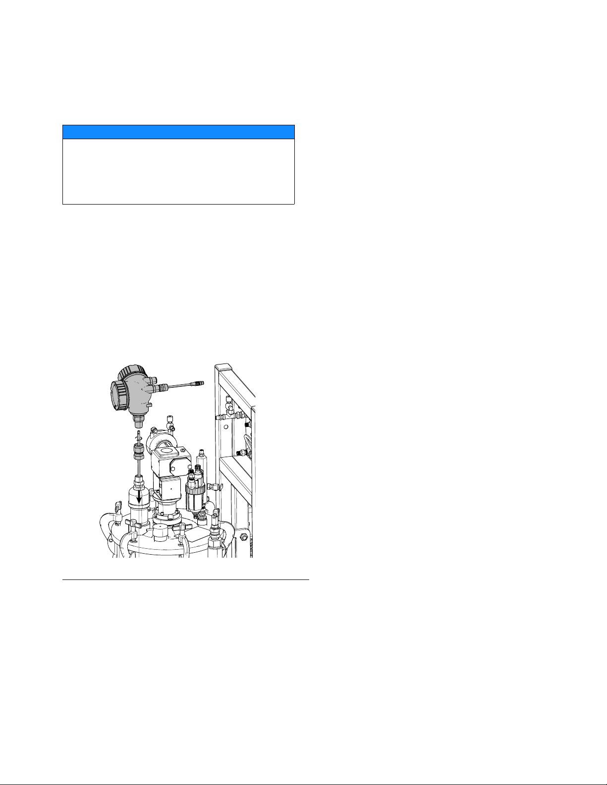
Prepare Level Sensor for Shipping
NOTICE
To prevent damage to the level sensor probe, do
not ship the feed module with the tanks empty and
the level sensor probe installed. This can cause the
probes to vibrate severely and damage the level
sensor head.
If possible, transport the tanks with at least 5 gallons (19
liters) of viscous material in the tanks, which is enough
for the material level to be above the probe end and will
prevent the probe from vibrating severely. If the tanks
cannot be shipped with material, perform the following
procedure.
1. Disconnect the 3/4 in. union below the level sensor
head. The level sensor head will be loose but will
not be removed. It is not necessary to remove the
level sensor cable.
Prepare Level Sensor for Shipping
WLD
F
IG
. 38
2. Use a pliers to grasp the flat on the rod and unscrew
it out of the sensor head.
3. Pull the probe up out of the tank and tape it to the
square tube frame securely to prevent vibration.
4. Replace the 3/4 in. union and level sensor head on
the tank lid. Tighten securely for shipping.
5. After shipment, see Install Level Sensor Probes
on page 19 to re-install.
3A2776D 49
Page 50

Download Data from USB
Download Data from USB
USB Logs
By default, the ratio spray logs record data every 60
seconds. This 60 second interval will record about 32
days of data if spraying 8 hours per day, 7 days per
week. To change the default, see Download Setup,
page 50. This log can hold up to 18000 lines of data.
Ratio Log 1
(Default log for download.) The ratio log records date,
time, machine number, job number, ratio, and batch volume while the system is in Spray mode.
Spray Log 2
The spray log records key data while the system is in
spray mode. It records A and B temperature, A and B
pressure, A and B flow, A and B batch totals, ratios,
restrictor adjustments, alarm codes, and commands.
NOTE: Once the ratio or spray log is full, new data automatically overwrites old data.
NOTE: After data in the ratio or spray log is downloaded
it remains in the USB module until it is overwritten.
Download Setup
Navigate to the System Setup screen. Change the number of hours of recorded data to download (default is
768 hours), by pressing and to move
to . Press to make the field selectable.
Press to scroll through each digit. Press
to save the new digit. Follow the same procedure
to change the time interval at which data will record
(default is 60 seconds). Exit the System Setup screen.
Download Procedure
Alarm Log 3
The alarm log records all alarm codes generated over a
two year period. This log should be used for troubleshooting purposes and cannot be deleted. This log can
hold up to 73000 lines of data.
Data Log 4
The data log records (every 120 seconds) all data that
occurs during spray mode over a two year period. This
log should be used for troubleshooting purposes and
cannot be deleted. This log can hold up to 43000 lines
of data.
NOTE: The 120 second recording period cannot be
adjusted.
1. Insert USB flash drive into USB port (DR). Use only
Graco-recommended USB flash drives; see Rec-
ommended USB Flash Drives, page 74.
NOTE: Inserting the USB flash drive while the sprayer is
running will stop sprayer operation.
50 3A2776D
Page 51

2. The USB download screen automatically displays,
and the selected log(s) automatically downloads.
The USB symbol flashes to indicate download is in
process.
NOTE: To cancel download, press while in pro-
cess. Wait for USB icon to stop flashing, and then
remove USB flash drive.
3. The USB icon stops flashing when download com-
pletes. The box below displays , which indicates the download was successful
4. Remove USB flash drive from USB port (DR).
5. Insert USB flash drive into USB port of computer.
6. The USB flash drive window automatically opens. If
it does not, open USB flash drive from within Win-
®
dows
Explorer.
Download Data from USB
7. Open Graco folder.
8. Open sprayer folder. If downloading data from more
than one sprayer, there will be more than one
sprayer folder. Each sprayer folder is labeled with
the corresponding USB serial number.
9. Open DOWNLOAD folder.
10. Open folder labeled with the highest number. The
highest number indicates the most recent data
download.
11. Open log file. Log files open in Microsoft
®
Excel® by
default. However, they can also be opened in any
®
text editor or Microsoft
Word.
NOTE: All USB logs are saved in Unicode (UTF-16) format. If opening the log file in Microsoft Word, select Unicode encoding.
3A2776D 51
Page 52

Maintenance
Maintenance
See the following table for maintenance tasks and frequency. See the following sections for details for each
task.
Frequency Task
• Before first use
• After first hour of operation
• After first day of operation
• Whenever TSL is discolored
or has seeped over the packing nut, and after sprayer has
been transported
Weekly Filters
As Needed Add oil to agitator
Adjust packing nuts
Seals
motor lubricators.
Use 10W or
10W-30 detergent
oil.
Clean the system
5. After TSL is added, tighten dosing valve packing
nuts 1/4 turn after nut contacts packings; about
145-155 in-lb (16-18 N•m).
TSL
TSL
ti20107a
Filters
Once a week check, clean, and replace (if needed) the
following filters.
• Main air inlet manifold filter; see XM PFP Repair Parts manual 3A2989, Replace Air Filter Element
section, for instructions.
Adjust Packing Nuts
NOTE: There must be no pressure when adjusting the
packing nuts. Air pressure in the feed tanks is too much.
1. Follow Pressure Relief Procedure, page 38,
including relieving air pressure in the tanks.
2. Fill A and B metering pump packing nuts with throat
seal liquid (TSL
3. After TSL is added, torque metering pump packing
nuts to 50 ft-lb (67.5 N•m). Follow instructions in
Xtreme Lowers manual 311762.
4. Fill A and B dosing valves packing nuts with throat
seal liquid (TSL).
™
).
• Air regulator filter (5 micron) on air control assembly; see XM PFP Repair - Parts manual 3A2989,
Replace Air Filter Element section, for instructions.
Seals
Once a week, check and tighten throat seals on metering pumps and dosing valves. Be sure to follow the
Flush Mixed Material, page 36, prior to tightening
seals.
52 3A2776D
Page 53

Clean the System
1. Ensure all equipment is grounded. See Grounding,
page 16.
2. Ensure the area where the sprayer will be cleaned
is well ventilated; and remove all ignition sources.
3. Turn off all heaters and allow equipment to cool.
4. Flush mixed material. See Flush Mixed Material,
page 36.
5. Perform Pressure Relief Procedure, page 38. This
includes flushing the system and parking the metering pumps.
6. Turn main power switch OFF.
Maintenance
7. Clean external surfaces only using a rag soaked in
solvent that is compatible with the spray material
and the surfaces being cleaned.
8. Allow enough time for solvent to dry before using
sprayer.
3A2776D 53
Page 54

Troubleshooting
Troubleshooting
Alarms
See Appendix B - Alarms, starting on page 76.
General Tips
The following information will help ensure the system is set up properly.
Grounding
• Ensure incoming power is grounded.
Air Supply
• Use at least a 3/4 in. (19mm) ID air hose, no longer
than 50 feet (15m).
• Ensure the first air pressure supply gauge stays above
80 psi (0.55 MPa, 5.5bar) while spraying.
• Ensure that the metering pump air pressure regulator
is set to at least 35 psi (2.4 bar) for spraying.
• Ensure that the solenoid air filter/regulator behind the
air panel is set to at least 80-85 psi.
• Check that the air filter element in the solenoid air filter/regulator behind the air panel is clean.
• Check that the main inlet air filter is clean.
Calibration
• Ensure dosing valve needle packing nuts are not
adjusted too tight. They should be snug when there is
no fluid pressure on the valve.
Motor Icing
Air motors accumulate ice in the exhaust valving and muffler under hot and humid conditions or under cold ambient
conditions. It can cause pressure loss or motor stalling.
• Ensure that the motor is left active when not spraying
to keep the internal bleed air working. Leave the motor
active in Spray mode or Manual mode to keep the
bleed air on.
Restrictions or Lost Pressure
• Check that the static mixer and whip hose are clean.
• Check the check valves for build up if spraying
fiber-filled material.
Mix Manifold
• Ensure that the ‘A’ and ‘B’ outlet hose sizes volume
balanced close to the mix ratio. Unbalanced hose sizes
can cause off-ratio slugs at the mix manifold during
pressure and/or flow transitions. See XM PFP Mix
Manifold manual.
• If less integration and mix hose is used than what is
recommended, ensure that “Fast Dosing” is selected in
the setup screens.
Software Version
• Ensure all modules in the system use software from
same token. Different software versions may not be
compatible.
• The latest software version for each system can be
found at Tech Support at www.graco.com.
• The ‘B’ fluid pressure should always be 15% to 30%
higher than ‘A’ pressure.
• A larger pressure difference indicates ‘A’ motor icing.
• A smaller or negative pressure difference indicates ‘B’
motor icing.
• Ensure that the NXT motor de-Ice bleed valves are
open to bleed warm air across the ice.
54 3A2776D
Page 55

Troubleshooting
Individual Control Module LED Diagnostic Information
The following LED signals, diagnosis, and solutions are the same for the display module, advanced fluid control
module (AFCM), fluid control cube, high power temperature control module (HPTCM), and USB module. LEDs are
located next to the module power cable.
Module Status LED Signal Diagnosis Solution
Green on System is powered up and power
--supply voltage is greater than
11 Vdc.
Blue
Voltage is being sent to the heater ---
(HPTCM only)
Yellow Internal communication in progress ---
Red solid Hardware failure Replace module.
Red flashing fast Uploading software ---
Red flashing slow Token error Remove token and upload software
token again.
Troubleshooting Table
NOTE: The sprayer operates using air pressure. Many problems are caused by inadequate air supply. The inlet air
pressure gauge cannot drop below 80 psi (0.5 MPa, 5.5 bar) while running.
Problem Cause Solution
Display not lit. No green light present on
back of display module.
Display not lit on system. Green light is
present on back of display module.
No electric power. Disconnect “off” or
breaker “open.”
Voltage jumpers not installed or configured in power junction box.
No green lights present on display, FCM,
or USB module.
No display power through CAN cable.
Green light in present on AFCM, but is
not present on USB module.
Green light is present on USB module. Check CAN cable. Replace if necessary.
Display module failed. Replace display module. See the XM
Reset main disconnect and breaker.
Install red jumpers in junction box terminal blocks. See Connect Power on
page 16.
Check for 24 Vdc on J1, pins 2 and 3, of
power supply. See Electrical Schematics
in the XM PFP repair manual. If there is
not 24 Vdc, replace power supply module. See XM PFP repair manual.
Check CAN cable. Replace if necessary.
See the XM PFP repair manual.
See the XM PFP repair manual.
PFP repair manual.
3A2776D 55
Page 56

Troubleshooting
Problem Cause Solution
Metering pumps do not run when Run
Mode is selected and the blue LED is illuminated.
Pump Test completes without error, but A
or B component has more than 750cc of
fluid in beaker.
Batch Test completes without error, but A
or B component has more fluid in beaker
than displayed on screen.
Sprayer does not start when start button
is pressed.
Fluid valves leaking at rod. Loose or worn packings. Tighten packing nut. If leak continues,
Fluid valve leaking between main and
outlet housings.
Material does not cure consistently. Ratio not set correctly. Check that correct ratio is set and set by
Air pressure to metering pumps too low Increase pressure to 50 psi (0.35 MPa,
3.5 bar) or greater.
Air pressure to metering valves is too low. Check air regulator behind main air
panel. Should be 80-85 psi
(0.55-0.59 MPa, 5.5-5.9 bar).
Circulation valves or mix manifold ball
valves are not open.
Air pilot lines are obstructed Check pilot lines for kinks or pinches.
Solenoid valve stuck. Actuate solenoid manually, if it does not
Air pilot valve(s) to motor stuck. Replace valve(s). See XM PFP repair
Metering valve(s) not opening. Service or replace valve(s). See XM PFP
Air motor stalled. See manual 311238.
Incorrect metering pumps were selected
in System Setup screens.
Air is trapped in fluid due to excessive
agitation, circulation, and heat. Fluid is
measured by volume when it is compressed under pressure.
See causes for previous pump test problem.
Faulty start switch or wire harness. Check start switch and wiring harness
Faulty stop switch or wiring harness. Check stop switch and wiring harness
O-ring on seat has failed. Replace both o-rings on that seat.
Material not mixing correctly. Test metering pump. Make sure mixer is
Material not properly conditioned before it
was added to sprayer.
Not using enough integration hose. Add more integration hose.
Open ball valves.
operate, replace solenoid. See the XM
PFP repair manual.
manual.
repair manual.
See Appendix A - User Interface Dis-
play beginning on page 58.
Repeat Pump Test with fresh fluid.
If the specific gravity of each fluid is
known, check samples by weight (750cc
x specific gravity equals weight in grams).
If weight is correct, extra volume in beaker is air.
See solutions for previous pump test
problem.
continuity; switch is normally open circuit.
See Electrical Schematics in the XM PFP
repair manual.
continuity; stop switch is normally closed
circuit. See Electrical Schematics in the
XM PFP repair manual.
replace packings.
volume.
clean; flush as needed.
Position mixer after integrator hose.
Mix material thoroughly.
Select “fast dosing” in setup.
56 3A2776D
Page 57

Troubleshooting
Problem Cause Solution
Poor spray pattern.
Also, see “System runs erratically” below.
System runs erratically. Air filter(s) clogged. Clean. Replace element(s).
Air supply relief valve opens. Air regulator set too high. Lower setting.
Flow rate too low. Air supply hose is too small or too long. Use 3/4 in. minimum ID air supply hose.
Receive ratio alarm after starting in spray
mode while using remote mix manifold.
Receive ratio alarm while using remote
mix manifold after a significant change in
pressure.
Fluid pressure too low. Increase metering pump pressure.
Fluid temperature too low. Increase fluid temperature.
Spray tip dirty or worn. Relieve pressure. Clean or replace tip.
Follow gun manual instructions.
Mix manifold, mixer, swivel, gun, or hoses
partially plugged or too restrictive.
Air supply hoses undersized. Replace hoses with appropriate size.
Air compressor undersized. Use larger air compressor.
Air supply pressure tank undersized. Use larger pressure tank.
Inlet air pressure gauge drops below 50
psi (0.35 MPa, 3.5 bar) while spraying.
A and/or B air motor has ice. Open air motor de-ice bleed air control.
Metering pump is binding. Repair lower. See XM PFP repair man-
Inadequate air supply. Use larger CFM compressor.
Air pressure to metering pumps too low. Increase metering pump air pressure.
Spray tip too small. Relieve pressure. Install larger tip. Follow
Mix manifold, mixer, swivel, gun, or hoses
partially plugged or too restrictive.
A and B hoses do not fill to correct pressure ratio simultaneously. Therefore,
spray time increases in order to balance
pressure. Ratio screen bar graph stays to
one side until pressure balances.
A and B hoses do not fill to correct pressure ratio simultaneously. Therefore,
spray time increases in order to balance
pressure. Ratio screen bar graph stays to
one side until pressure balances.
Inspect parts for cured material. Clean or
replace, or use larger hoses and mixer.
See solutions above for system runs
erratically problem.
Allow ice to melt. Dry the compressed air.
Heat the compressed air. Use a smaller
tip and lower flow rate.
ual.
See Technical Data, page 85.
gun manual instructions.
Inspect parts for cured material. Clean or
replace, or use larger hoses and mixer.
Pressurize outlet hoses in manual A/B
pump mode. Then start spray mode.
Select correct hose size to balance your
volume ratio. See XM PFP Mix Manifold
manual.
Pressurize outlet hoses in manual A/B
pump mode. Then start spray mode.
Select correct hose size to balance your
volume ratio. See XM PFP Mix Manifold
manual.
Change pressure slowly while spraying.
3A2776D 57
Page 58

Appendix A - User Interface Display
Appendix A - User Interface Display
The user interface display is divided into three main
functions: Setup, Command, and Automatic.
Setup Mode Screens (key to right)
Use these screens to:
• set desired mix ratio by volume
• set weight ratio and tolerance for ratio checks
• configure system settings
• set potlife parameters
• enable/disable functions, displays, and display
components
• set which USB logs to download
• schedule maintenance parameters for alarms
and advisories
• set pressure and temperature limits
• set tank “fill” and “full” levels
NOTE: Some setup functions must be enabled from the
Enable Setup screens before users can change or set
configurations. See Enable Setup Screens, page 63,
for instructions.
• download USB logs.
Change a Setting
All settings are changed in the same manner:
1. Navigate to the desired screen. See Operator
Command Mode Screens on page 66, or Setup
Mode Screens on page 59.
2. Once in the desired screen, use the arrow keys to
navigate to the item that you wish to change.
3. Press enter to enter editing mode.
4. Use the arrow keys to change the selection or
value.
5. Press enter again to save the change or press
to cancel the change.
Alarms
Operator Command Mode Screens (key to left or
removed)
Use these screens to:
• run pumps, including flush, circulate, and prime
procedures
• park metering pumps so pump rods are down
when not in use
• mix and spray
•view mix ratio
• run pump tests
• run batch dispense ratio tests
• run valve leak checks
• view dispense totals
•view alarms
• diagnose alarms
• clear alarms
• set and view A heater, B heater, and hose bundle temperatures
• view tank temperatures and levels
Automatically Displayed Screens
See Appendix B - Alarms, starting on page 76.
These screens are shown when
• The potlife timer alarms to notify the user that
material is about to cure in the system.
58 3A2776D
Page 59

Appendix A - User Interface Display
Setup Mode Screens
To enter the Setup Mode screens, turn the setup key lock (DJ) to the right. The key cannot be removed when in
Setup Mode. See F
Setup Mode Screens Navigation Diagram
Software VersionsHome / Volume Mix Ratio
IG
. 7 on page 12. Some setup screens can be disabled, see Enable Setup Screens on page 63.
Ratio Test
Temperature
Pressure
Tank Fill
Enable Options 3
Maintenance 2Maintenance 1
Enable Options 2Enable Options 1
Date/Time/Units System/USB
(From All Screens)
Potlife/Hose Length
3A2776D 59
Page 60
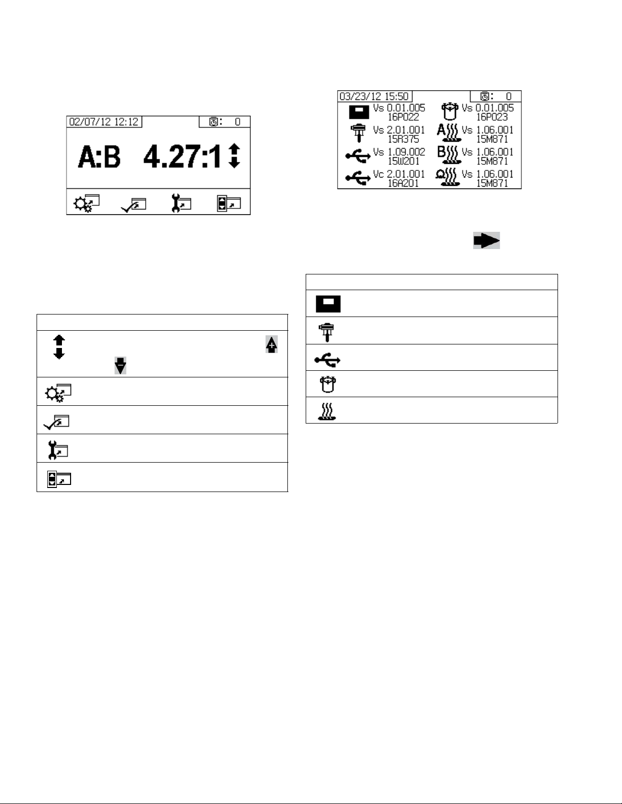
Appendix A - User Interface Display
Home Setup Screens
Home
Home is the first screen that displays in Setup mode. It
shows the current metering pump ratio and enables
users to change the mix ratio and access the following
screens: system setup, enable/disable functions, maintenance setup, and limits. Refer to the following table for
more details.
Icon Function
Increase or decrease mix ratio. Press
and to change the mix ratio.
Navigate to jump to system setup screens.
Software Versions
This screen displays the versions and part number of
the system components. Refer to the following table for
details. To access this screen, press from the
Home Setup screen.
Icon Function
Display module version (Vs) and part number
Advanced fluid control module version (Vs)
and part number
USB version (Vs) and part number
USB Configuration (Vc) and part number
Fluid control cube version and part number
Navigate to enable/disable options
B, and Hose version and part number (Vs)
screens.
Navigate to maintenance setup screens.
Navigate to pressure and temperature limits setup screens.
.
High power temperature control module A,
60 3A2776D
Page 61
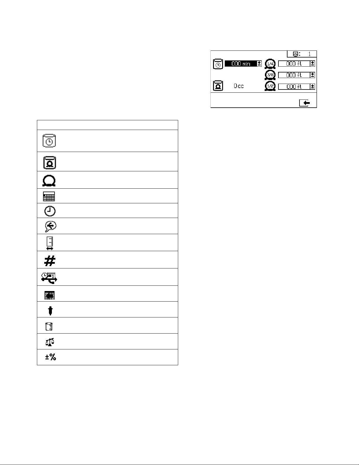
Appendix A - User Interface Display
System Setup Screens
System Setup enables users to configure system settings for fluid control and operator interaction. Refer to
the following table for details.
NOTE:
Some system settings must be enabled from the Enable
Setup screens before users can change or set configurations. See Enable Setup Screens, page 63, for
instructions.
Icon Function
Set number of minutes before mixed material will set in hose. Resets after material
volume set by user is passed through hose.
Indicates total hose volume. Always displayed in cc units.
Set length of hose after mix manifold. Used
to indicated total hose volume.
Set calendar date and format.
Set time.
Potlife/Hose Length
This screen enables users to set the potlife timer, and
length of each mixed material hose specific to the system. The total mixed material volume is then calculated
and displayed on the page. The potlife time displays in
the upper right corner.
When the fluid flow stops the displayed potlife time
counts down in one minute intervals. The timer automatically resets when the calculated mixed fluid volume is
dispensed.
Set USB language.
Set units of measurement desired for display, such as fluid and temperature.
Set sprayer number if using more than one
sprayer.
Set how often data will record to USB ratio
and spray logs.
Set number of hours of recorded data to
download to USB flash drive.
Set the A and B side metering pump sizes.
Volume ratio reference
Weight ratio reference
Ratio Pass Tolerance
3A2776D 61
Page 62

Appendix A - User Interface Display
Date/Time/Units
Use this screen to set day, time, and units that will be
displayed on each screen. The selected language is
used in each USB log. The following USB languages are
supported: English, French, German, Spanish, Russian,
Italian, Chinese, Japanese, Korean, Norwegian, and
Polish.
System Number and USB Settings
Tank Fill
Graco recommends leaving all of the settings on this
screen at the factory defaults.
This screen can be used to adjust tank level settings.
The default settings from the top of the screen to the
bottom are 20, 13, 11, and 4, when gallons is the
selected unit of measure on the system. The level sensors cannot detect fluid under the four gallon level.
The top and bottom settings are used for maximum and
minimum settings for the tanks on this machine and
should not be changed. If the tank level goes beyond
one of these settings, an alarm will result. See Alarm
Code Troubleshooting on page 79.
Use this screen to set the sprayer number if using more
than one sprayer, and to configure the number of hours
downloaded to external USB flash drive and how often
the data will record, and set the A and B side metering
pump size. This system uses a 220 cc pump on the A
side and a 180 cc pump on the B side.
The middle two settings are for maintaining the tank
level when automatic tank filling is on. Automatic tank
filling will maintain the fluid level in the tank to between
these two levels. Changing these levels will move the
arrows shown next to the tanks on the Supply screen.
When using fiber-filled or compressible fluids, do not set
the high arrow too high. When the tank is depressurized
with too much fluid in the tanks, the fluid can expand
and rise up into the tank lid air passages.
Each value must be larger than the value below it.
Ratio Test
Use this screen to set the ratio by weight (middle number), and the ratio by weight tolerance (bottom number).
The ratio by volume (top number) is displayed but cannot be changed on this screen. These values determine
whether the ratio test passes. See Home screen, on
page 60, to change the ratio by volume.
62 3A2776D
Page 63

Appendix A - User Interface Display
Enable Setup Screens
Use these screens to enable and disable functions,
screens, and USB download log files. Checked boxes
indicate the function, screen, or log file is enabled. Refer
to the following table for details.
To enable and disable functions, screens, and USB log
files, press from the Home Setup screen. Once
in the Enable Setup screen, press and to
scroll through each subscreen. Press and to
scroll through each field within the subscreens, and
press to enable or disable each. Press to
return to the Home Setup screen.
Icon Function
USB data download function. Disable this
function to prevent operators from changing USB settings.
NOTE: Even if this function is disabled,
selected USB logs will still be downloaded.
Enable or disable totalizer screens.
Enable or disable batch totalizer clear function.
Display potlife timer on all screens.
Enable or disable potlife timer setup
screen.
Display flow rates on run screens
Display A and B pressures on run screens.
Icon Function
Enable or disable dosing valve maintenance setup screen.
Enable or disable incoming air filter maintenance setup screen.
Enable or disable limits (pressure and temperature) screens.
Fast dosing function. Enable function to
minimize B side dose size and increase
dosing rate. See table below.
Use this function with short integration
hose. The system will attempt to hold the
dosing sizes below the advisory level.
Display time on all screens.
Enable or disable downloading individual
USB log files (1-4).
Enable or disable the A or B feed system.
When disabled, that feed system will not be
shown on the user interface and no alarms
will be generated for that feed system. This
enables the user to use the air shutoff
valve on the feed pump to turn on and off
the feed pumps if there is a problem with
the feed system.
Fast Dosing Function
Fast Dosing Advisory QTAE Alarm QDAE
ON 20 cc 30 cc
OFF 35 cc 45 cc
Display A and B heater outlet temperatures
on run screens.
Enable or disable ability to change metering pump size in system setup screens.
Enable or disable ratio screen. If enabled,
ratio screen will automatically display after
sprayer runs for 10 seconds.
Enable or disable pump maintenance setup
screens.
3A2776D 63
Enable Setup Screen 1
(Shown with factory default settings.)
Page 64

Appendix A - User Interface Display
Enable Setup Screen 2
(Shown with factory default settings.)
Enable Setup Screen 3
(Shown with factory default settings.)
Maintenance Setup Screens
Use these screens to set maintenance setpoint amounts
for pumps and dosing valves. The maintenance setup 2
screen enables users to schedule the number of days
between changing the main incoming air filter before a
reminder advisory will sound.
The number displayed below each selectable field indicates the amount of material dispensed, counting up to
the setpoint requiring maintenance.
Icon Function
Set amount of material moved through
pump that will result in a maintenance
warning.
Set amount of material moved through dosing valve that will result in a maintenance
warning.
Set number of days between changing the
main incoming air filter before a reminder
advisory is issued.
Maintenance Setup 1
Maintenance Setup 2
64 3A2776D
Page 65

Appendix A - User Interface Display
User Limits Setup Screens
Use these screens to set and adjust pressure and temperature limits for both metering pumps, including limits
that will issue advisories and alarms. Refer to the following table for details.
The allowable range for the temperature setpoint is 34° 160°F (1° - 71°C). If the temperature or pressure setpoint is zero, pressure limits and alarms are disabled.
NOTE: The B metering pump pressure always runs
10-20% higher than the A metering pump pressure.
Icon Function
Set and adjust pressure limits for both
metering pumps during spray mode.
Set and adjust high and low temperature
limits for both fluid heaters during spray
mode.
Set target pressure or temperature.
Set and adjust limits above or below target
value that if exceeded will issue an advisory. Used with pressure and temperature
limits.
Set and adjust limits above and below target value that if exceeded will issue a
alarm. Used with pressure and temperature
limits.
Process Pressure Limits (for spray mode)
Process Temperature Limits (for spray mode)
3A2776D 65
Page 66

Appendix A - User Interface Display
Operator Command Mode Screens
To enter the Operator Command Functions screens, turn the setup key lock (DJ) to the left.
See F
IG
. 7 on page 12.
Operator Command Mode Screens Navigation Diagram
Supply Screen
in each section
Go to primary screen
Maintenance 2
Maintenance 1
Totalizer
Information Screens
Alarm Information
Alarm Log
Valve Test
Test Screens
(Pump Volume Test shown)
Park Pump
(Spray Mode shown)
Run (Fluid Control) Screens
66 3A2776D
Pump Mode
Batch Test
Pump Test
Ratio
Spray Mode
Weight/Volume
Restrictor
Page 67

Appendix A - User Interface Display
Run (Fluid Control) Screens
Run (fluid control) is the first screen displayed at power
on. It enables users to spray material, and operate and
park metering pumps. Run consists of two screens:
power on/enter and ratio mode.
The power on/enter screen cycles through power on
mode, spray mode, pump mode, and park mode. It displays the current ratio setpoint when in spray mode and
may also display: pressure, temperature and flow rate if
these options are enabled.
The ratio screen displays the current ratio and monitors
the B side restriction adjustment.
Icon Function
Spray:
proportion and spray material.
Icon at bottom of screen:
metering pumps are active. Press repeatedly to cycle through metering pump A,
metering pump B, and both metering
pumps.
Icon in rectangle:
pumps.
Operate the A metering pump only (prim-
ing, flushing).
Operate the B metering pump only (priming, flushing).
Operate both metering
Park Metering Pumps:
to bottom of the stroke.
Ratio:
jump to ratio screen.
Select which
run metering pumps
Spray Mode
Users must be in this mode to spray or proportion material. Press the button below the spray icon to enter this
mode.
Pump Mode
Users must be in this mode to operate metering pumps
for priming or flushing. Press the button below the
metering pump icon to enter this mode. Continue pressing the metering pump icon button to cycle through
metering pump A, metering pump B, and both metering
pumps.
Power On/Enter Mode
Power On/Enter Mode is the default screen when users
enter Fluid Control.
NOTE: This screen remains blank until a mode is
selected.
3A2776D 67
Page 68

Appendix A - User Interface Display
Park Mode
Users must be in this mode to park the metering pump
fluid rods to the bottom of their stroke. Press the button
below the park icon to enter this mode.
Ratio Mode
This screen displays the current ratio or the adjust
restriction screen. To access this screen, press .
NOTE: If the field is enabled on the Enable
Setup screen, the Spray Mode screen will be replaced
by the bar graph screen after 10 seconds of spray time.
Adjust Restriction Screen
This screen shows the balance of the A and B fluid
sides. If the bar graph remains all the way to the right,
there is not enough restriction on the B side and adding
more restriction will lower the dosing size. If the bar
graph remains all the way to the left, there is too much
restriction on the B side. Reducing restriction will reduce
dosing size.
Press to return to the Spray Mode screen.
Icon Function
Display Ratio:
fluid mix ratio.
Display Adjust Restriction Screen
show the accuracy of the
68 3A2776D
Page 69
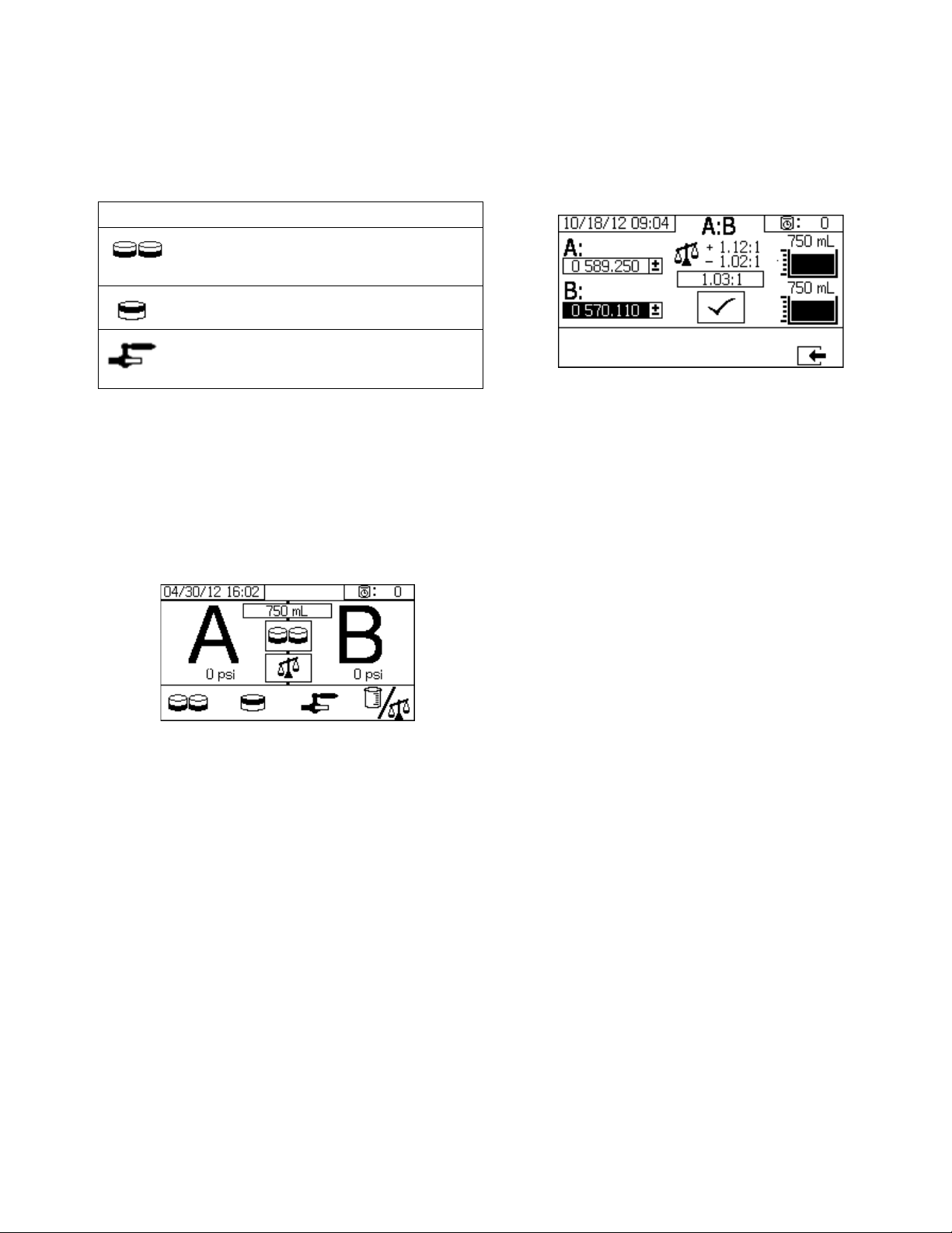
Appendix A - User Interface Display
Test Screens
Use this screen to run batch dispense tests, pump tests,
and down stream valve leak tests.
Icon Function
Pump Test:
B; verifies pump selection, operation, and
metering.
Batch Dispense:
amounts of A and B with a selectable total.
Down Stream Valve Leak Test:
valves after the dosing valves hold pressure.
Pump Test
Use this screen to dispense a fixed 750 ml volume of
material from each metering pump. When the metering
pump is active it flashes in black on the screen. When
the metering pump completes dispensing it displays
gray on the screen. This test will stall the A and B metering pumps on each stroke to verify they hold pressure.
See Pump and Metering Test procedure on page 40.
dispenses 750cc of each A and
dispenses proportioned
test if
If weight mode is used, enter the net weights of each
dispensed material in the respective input boxes on this
screen. If they are within the ratio tolerance set on the
Setup Mode Ratio Test screen, a check will appear in
the box. The results are entered into the USB logs.
Confirm Pump and Metering Test
This screen displays when the pump test completes
without error. This screen displays the target weight of
material dispensed into each beaker from each metering
pump.
3A2776D 69
Page 70
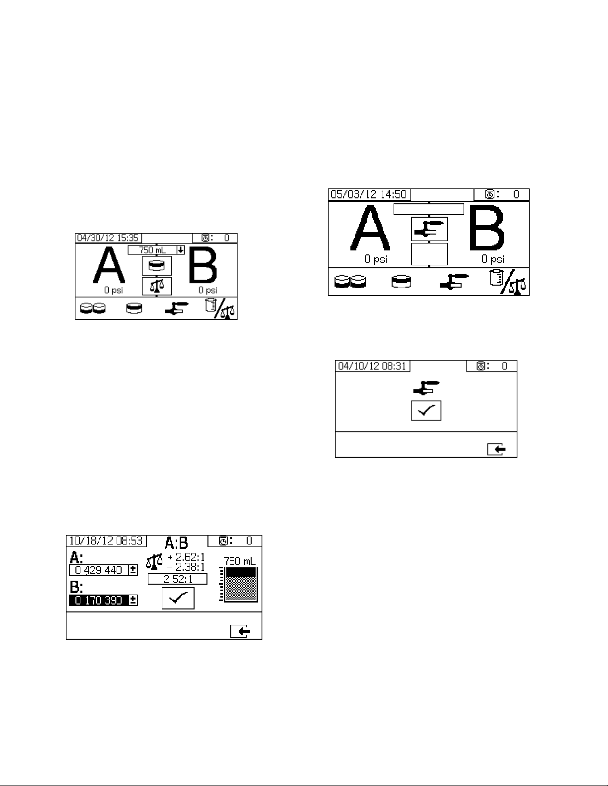
Appendix A - User Interface Display
Batch Dispense or Ratio Test
Use this screen to dispense a selected total volume of
material on ratio. For example, 1000 ml at 4:1 = 800 ml
of A + 200 ml of B. The total batch volume can be
selected from the drop down menu. The dispense material can be used to check the ratio or to mix together and
use in production. See Batch Dispense or Ratio Test
procedure on page 42.
When the metering pump is active it flashes in black on
the screen. When the metering pump completes dispensing it displays in gray on the screen.
Confirm Batch Dispense Test
Down Stream Valve Leak Test
Use this screen to test for closed or worn valves down
stream of the A and B dosing control valves. It can be
used to test the mix manifold shutoff/check valves or
any remote circulation valves.
While running the test, if there is continuous metering
pump movement on the A or B side, an error will be
issued. The error indicates a leak in the valve.
Confirm Valve Leak Test
This screen displays when the valve leak test completes
and indicates whether the test was successful.
This screen displays when the batch dispense test completes without error. This screen displays the selected
ratio between the metering pumps and the desired
weight of material dispensed from each metering pump.
The gray at the bottom of the beaker represents the
material dispensed by metering pump A. The black at
the top of the beaker represents the material dispensed
by metering pump B.
If weight mode is used, enter the net weights of each
dispensed material in the respective input boxes on this
screen. If they are within the ratio tolerance set on the
Setup Mode Ratio Test screen, a check will appear in
the box. The results are entered into the USB logs.
70 3A2776D
Page 71
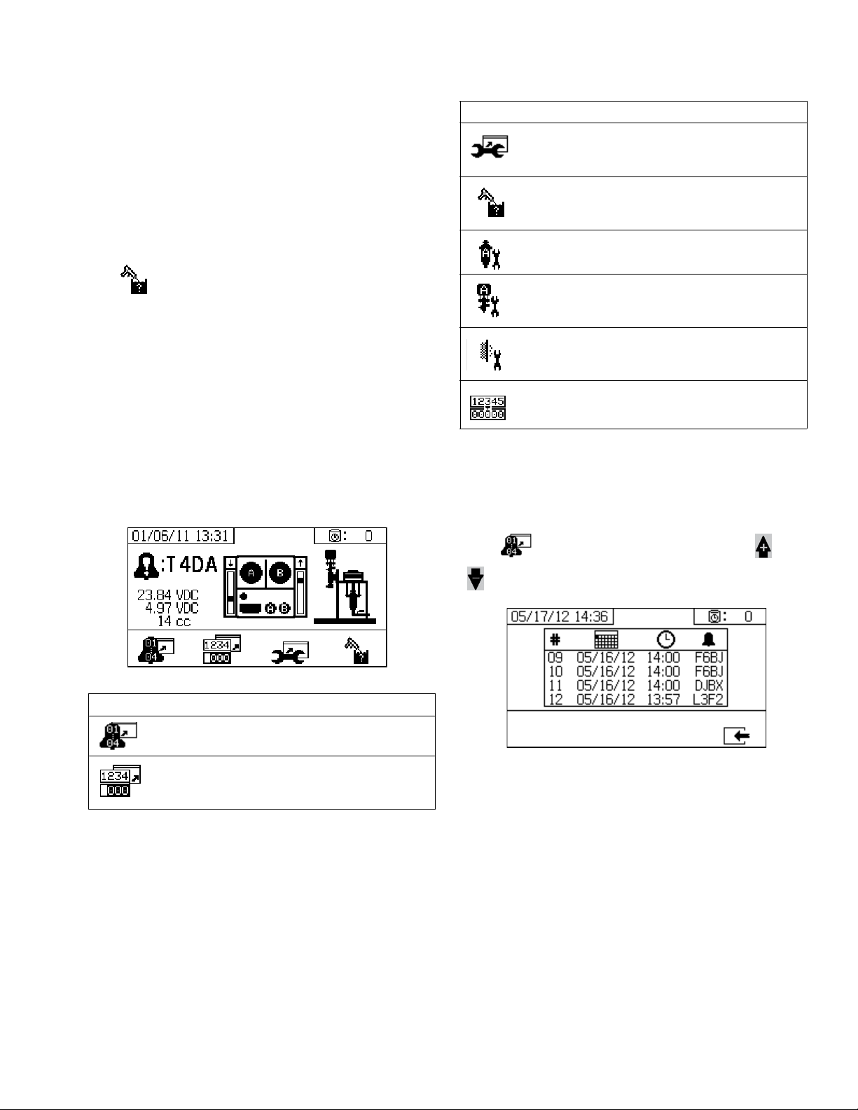
Appendix A - User Interface Display
Information Screens
Use this screen to view alarm diagnostic information,
alarm logs, and pump batch and grand totals. These
screens also enable users to view maintenance information for pump and check valves, including the maintenance schedule.
NOTE:
If the potlife timer is enabled, the Flush Confirm
icon displays.
Alarm
The Alarm screen displays the specific alarm code.
There are two levels of error codes: alarms and advisories. A solid bell icon with an exclamation point and
three audible alerts indicate a alarm. And an outlined
hollow bell icon and a single audible alert indicate an
advisory.
Additionally, this screen displays the location of the error
with the top view and side view of the system. Refer to
the following table and subsections for more details.
Icon Function
Go to maintenance screen. Allows user to
view maintenance information.See Mainte-
nance Setup 2, page 64.
Flush confirm. Use when the potlife timer is
enabled. Press button to confirm flush
before a potlife advisory is issued.
Amount of material moved through pump
that will result in a maintenance warning.
Amount of material moved through dosing
valve that will result in a maintenance
warning.
Number of days between maintenance
cycles that will result in a reminder advisory.
Clear batch totalizers or maintenance
counters.
Alarm Log
Use this screen view details regarding alarms received,
including the date, time, and alarm code for the last 16
alarms. Up to four pages of alarms are available.
Icon Function
Go to Alarm log. Use up and down arrows
to scroll through list of the past 16 errors.
Go to totalizer screen. Allows users to view
the grand and batch totals for each pump
and both pumps combined.
Press to access the alarm log. The press and
to scroll through each page of alarms.
3A2776D 71
Page 72
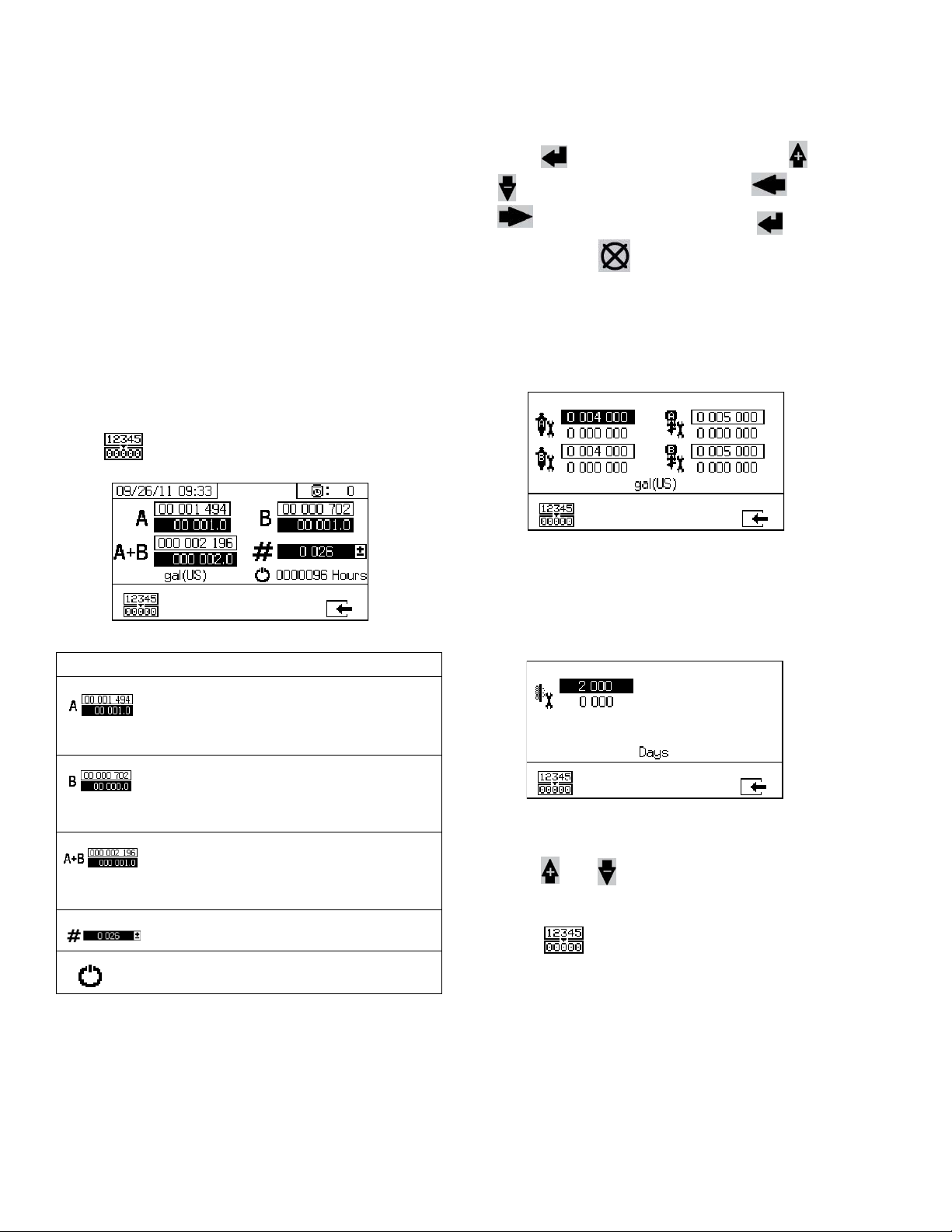
Appendix A - User Interface Display
Totalizers and Job Number
Use this screen view the grand and batch totals for each
pump and both pumps combined. The units of measurement are displayed on the bottom of the screen and displayed in the units of measurement selected during
setup.
Grand total is the amount of material the system has
dispensed during its lifetime. Batch total is the amount of
material dispensed since the last user reset.
A job number can be entered at the beginning of each
spray job. This helps to organize the USB spray log.
Clear Batch Totalizer
To clear the batch totalizer values for A, B, and A+B,
press to set all values to zero.
Change Job Number
1. Press to highlight the first digit. Press and
to change the number and press and
to move to the next digit. Press to save
the number or to cancel.
Maintenance 1 Screen
Use this screen view setpoints for the amount of material that needs to move through both pumps and dosing
valves that will result in a maintenance warning.
Icon Function
Displays batch total and grand total for
pump A. The grand total is displayed at
the top, and the batch total is displayed at
the bottom.
Displays batch total and grand total for
pump B. The grand total is displayed at
the top, and the batch total is displayed at
the bottom.
Displays batch total and grand total for
both pumps combined. The grand total is
displayed at the top, and the batch total is
displayed at the bottom.
Displays job number for each spray
period.
Number of hours system has been running
Maintenance 2 Screen
Use this screen view number of days between changing
the main incoming air filter before a reminder advisory is
issued.
Reset Maintenance Counter
1. Press and to scroll through and select the
maintenance field to reset.
2. Press to reset the maintenance counter to
zero.
72 3A2776D
Page 73

Supply Screen
Use these screens to turn on and off automatic tank filling, turn on and off the fluid heaters and hose heat, and
change temperature setpoints for each fluid heater and
for the hose heat.
When automatic tank filling is on, the feed pump will
begin pumping fluid into the tank when the fluid level
goes below the bottom arrow. It will continue filling until
the fluid level reaches the upper arrow. When the feed
pump is running, the small circle on the screen next to
the tank will have a black background. In order for automatic tank filling to run, the director valve (DC) must be
in the DOWN position, and the RAM slider valve (DA)
and air motor slider valve (DF) must both be in the ON
position with proper air pressure air supplied to the RAM
and air motor. See Feed Pump Air Controls on
page 11.
Appendix A - User Interface Display
This screen also displays the current volume of each
tank and the current temperature measured at each fluid
heater, at the hoses, and in each tank.
Icon Function
Turn on and off automatic tank filling
Turn on and off the A fluid heater
Turn on and off the B fluid heater
Turn on and off the hose heat
3A2776D 73
Page 74

Appendix A - User Interface Display
Automatically Displayed Screens
Potlife Screen
This screen automatically displays when a potlife advisory occurs. The screen automatically closes when the
advisory ends or the user presses the flush confirm button. Refer to the following table for more details.
Icon Function
Advisory has been issued.
Potlife timer is enabled.
Time after potlife expires. Starts at 0.00
and counts down in negative one minute
intervals.
Press to mute advisory buzzer.
Press to confirm that mixed hose has been
flushed. Resets potlife timer.
Icon Function
Flashes while data download is in process.
Check mark appears after download completes. Indicates download was successful.
If download was not successful,
appears.
Displays total memory to download and
remaining memory left to download.
Displays time remaining for log download
to complete.
Press to cancel download. If download is
cancelled, remove USB flash drive.
Indicates which log(s) will be downloaded.
Recommended USB Flash Drives
It is recommended that users use the Diesel 4GB USB
USB Screen
This screen automatically displays and the selected
log(s) automatically starts downloading when a USB
flash drive is inserted into the control box. See F
on page 75 to see an example of a downloaded log file.
Inserting the USB flash drive while the sprayer is running will automatically stop sprayer operation. Removing the USB flash drive automatically closes the USB
screen.
The log selected for current download is displayed in the
single box next to the USB icon. The other available
logs are displayed in the boxes on the right side of the
screen. Refer to the following table for more details.
74 3A2776D
IG
. 39
flash drive (16A004) included with the PFP sprayer for
data download. However, the following USB flash drives
can also be used, but are not available through Graco.
• Crucial Gizmo!
JDO4GB-730)
• Transcend JetFlash
(model TS4GJFV30)
™
4GB USB flash drive (model
®
V30 4GB USB flash drive
Page 75

Appendix A - User Interface Display
FIG. 39: Example Ratio and Spray Logs
3A2776D 75
Page 76
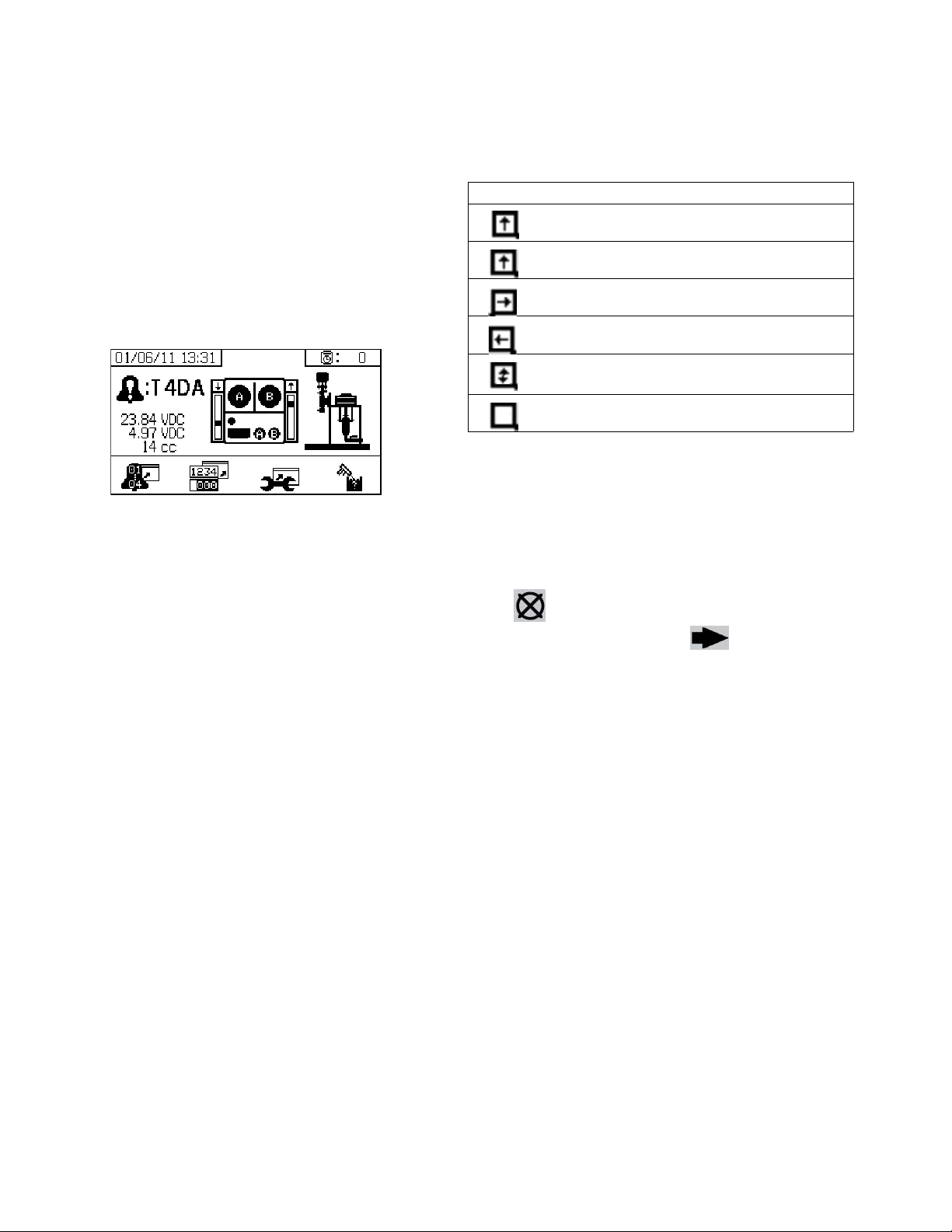
Appendix B - Alarms
Appendix B - Alarms
Alarms Overview
View Alarms
When an alarm occurs the alarm information screen
automatically displays. It shows the current alarm code
along with a bell icon. It also shows the alarm location
with top and side views of the sprayer.
There are two levels of alarms: warnings and advisories.
A bell icon indicates an alarm. A solid bell icon with an
exclamation point and three audible alerts indicate a
warning. And an outlined hollow bell icon and a single
audible alert indicate an advisory.
Advisories are notifications that require attention but not
immediately. Alarms require immediate correction;
therefore, sprayer operation automatically stops.
Icon Function
Moving up
Moving down
Top changeover
Bottom changeover
Both reed switches are active. Start of
changeover or motor icing problem.
Blank: No reed switch signal - error
Diagnose Alarms
See Alarm Code Troubleshooting for causes and
solutions to each alarm code.
Clear Alarms
Press to clear alarms and advisories. From the
alarm information screen, press to return to the
run (fluid control) screen.
This screen also shows diagnostic information. There
are three lines of data on the left side. The top line
shows the power supply. This should be 23-25 Volts.
The middle line shows the voltage supplied to all sensors connected to the Advanced Fluid Control Module.
This should be between 4.9-5.1 Volts.
The center of the screen shows linear sensor vertical
bar graphs and reed switch information. The A side
information is on the left and the B side information is on
the right. Linear sensor position is displayed on the bar
graph that goes up and down when the metering pump
moves. This bar graph should move from top to bottom
to match each metering pump stroke.
The state of the two reed switches in each air motor are
shown with the arrow above each vertical bar graph.
76 3A2776D
Page 77

Appendix B - Alarms
Alarm Code Key
Use the following table as a quick guide to determine alarm code meaning.
Digit 1 Digit 2 Digit 3 Digit 4
Code Event Code Mode (Char 2) Code Location (Char 3) Code Zone (Char 4)
A Current 1 Low Alarm A Material A 1 Tank A
F Flow 2 Low Deviation B Material B 2 Tank B
L Tank Level 3 High Deviation C Controller A Heater A
P Pressure 4 High Alarm D Output Discharge B Heater B
R Ratio 5 Calibration F Input Feed C Level Sensor A
T Temperature 6 Sensor Failure M Power Supply D Level Sensor B
V Voltage 7 Unexpected
Non-Zero Value
8 Unexpected
Zero Value
9 Unstable K Reed Switch
C Communication A Loss P Display
D Pump A Runaway X System
D Cavitation
E Time-out
F Stall Up
G Stall Down
J Linear Sensor
K Reed Switch
M Maintenance A Pump
EValve
GFilter
Q Proportioning D Overdose
PPotlife
T Dosing Time
P Pneumatic Supply E Hose
R Recirculation H Heater Hose
J Linear Sensor
3A2776D 77
Page 78

Appendix B - Alarms
Possible Alarms by Mode
The following table outlines the alarms that you may receive while operating the system. The alarms are categorized
according to each mode.
Mode Control Logic Alarms
Spray Dosing valves close for startup test; green light blinks. --
If fluid pressure is under 1000 psi (7 MPa, 70 bar), STOP. P1AX
If pumps move (indicating internal leakage), STOP. F7AX, F7BX
If fluid pressure is more than 103% of allowed maximum, air motor shuts off until fluid
pressure drops.
If is pressure more than 110% of allowed maximum, STOP. P4BX
Dosing valve A opens, and dosing valve B cycles to maintain ratio. --
A and B blue lights illuminate when dosing valves are operating. --
If there is not enough B component to hold ratio, dosing valve A closes momentarily. R5BE
If A or B component is more than 5% off ratio setpoint, STOP. R1BE, R4BE
If A dose size is too large, STOP. QDAE
A and B dosing valves close momentarily at each pump changeover. --
Park Both dosing valves open; A and B blue lights turn on. --
User opens circulation valves or sprays gun. When pump reaches bottom stroke the
blue light turns off.
If park does not complete in 10 minutes, turn off air to both motors. DEAX, DEBX
Circulation A and/or B dosing valves close and motor air turns on. --
If fluid pressure exceeds 3000 psi (21.0 MPa, 210 bar) on the A pump, receive yellow
light advisory.
If fluid pressure exceeds 5600 psi (39.2 MPa, 392 bar) on the A pump, STOP. P4AX
If no movement in 10 minutes, turn off air to both motors. DEAX, DEBX
Pump Test Both dosing valves close; green light blinks. --
If fluid pressure is under 1000 psi (7.0 MPa, 70 bar), STOP. P1AX, P1BX
If pumps move (indicating leakage) STOP. F7AX, F7BX
Turn on A blue light, open A dosing valve, user opens sampling valve. --
Close A dosing valve on upstroke; check for no movement. DFAX
Close A dose valve on down stroke; check for no movement. DGAX
Open A dose valve and dispense total of 750 ml material, close valve, turn off blue
light.
Repeat for B side. DFBX, DGBX
If both pumps pass pump test, display shows two beakers of 750ml each. --
Batch Dispense Test
Valve Test If fluid pressure is not 1000 psi (7 MPa, 70 bar), STOP. P1AX
User selects total volume desired. --
Open A dosing valve, turn on blue light, user opens sampling valve, turn off blue light
when complete.
Open B dosing valve, turn on blue light, user opens sampling valve, turn off blue light
when complete.
Display shows volume of A and B components at end of batch dispense test. --
Check for no movement of pumps (stall within 10 seconds). F7AX, F7BX
None
--
P4AX
--
--
--
78 3A2776D
Page 79

Appendix B - Alarms
Alarm Code Troubleshooting
NOTE: See PFP Plural-Component Sprayers Repair-Parts manuals for non-alarm based troubleshooting.
* Indicates the alarm is user-defined.
Alarm
Code Alarm Problem
A4DA
A4DB
A4DH Hose Heater Over-Current
A8DA
A8DB
A8DH Hose Heater No Current
A9DA
A9DB
A9DH Hose Heater Unexpected
CACA
CACB
CACH Temperature Control Module
CACP Display Has No Signal Always No display communication signal. Check cable connections. Replace
DAAX
DABX
DDAX
DDBX
DEAX
DEBX
A/B Material Heater
Over-Current Alarm
Alarm
A/B Heater No Current Alarm Always Temperature Control Module is bad. Replace module.
Alarm
A/B Material Heater Unexpected Current Alarm
Current Alarm
Temperature Control Module
Heater Loss Of Communication Alarm with A/B Material
Heater
Loss of Communication
Alarm with Hose Heater
Pump Runaway; Above 80
CPM For 10 Sec.
Pump Cavitation; Dives More
Than 1/2 Of Stroke.
Pump Does Not Move In 10
Minutes.
When
Active Cause Solution
Always Temperature Control Module is bad. Replace module.
Heater is bad. Repair heater.
Always Temperature Control Module is bad. Replace module.
Heater is bad. Repair heater.
Heater is bad. Repair heater.
Heater wiring is bad. Fix heater wiring
Always Temperature Control Module is bad. Replace module.
Heater is bad. Repair heater.
Heater wiring is bad. Fix heater wiring
Always Temperature Control Module is bad. Replace module.
Heater is bad. Repair heater.
Always Temperature Control Module is bad. Replace module.
Heater is bad. Repair heater.
Always Network communication cable is
bad.
Temperature Control Module network address is wrong.
Temperature Control Module is bad. Replace module.
Always Network communication cable is
bad.
Temperature Control Module network address is wrong.
Temperature Control Module is bad. Replace module.
Machine powered down in spray
mode.
Always No material in pump or lines; no fluid
restriction.
Spray No fluid or valve closed. Refill supply and open inlet valve.
Material is too cold or thick. Increase material temperature to
Pump inlet check valve not closing. Clear debris from check valve. Or
Feed pump not providing material. Check feed pump (if used).
Inlet strainer plugged (if used). Check and clean strainer. See XM
Park or
Pump Test
Recirculation valves were not
opened to allow flow.
Replace communication cable.
Set module network address.
Replace communication cable.
Set module network address.
display.
See XM PFP Repair manual.
Press stop button before turning off
power.
Refill material in tank or hoses;
install fluid tip.
reduce viscosity. See Spray, page
32. Shear material with agitation to
reduce viscosity.
replace ball, seat, and seal.
PFP repair manual.
Open recirculation valves.
3A2776D 79
Page 80

Appendix B - Alarms
Alarm
Code Alarm Problem
DFAX
DFBX
DGAX
DGBX
DJAX
DJBX
DKAX
DKBX
F6AJ A Air Motor Linear Sensor
F6AK A Air Motor Reed Switch Sig-
F6BJ B Air Motor Linear Sensor
F6BK B Air Motor Reed Switch Sig-
F7AX
F7BX
L2F1
L2F2
Pump Did Not Stall Against
Fluid Pressure On Up Stroke
Only.
Pump Did Not Stall Against
Fluid Pressure On Down
Stroke Only.
Pump Motor Linear Sensor
Has No Signal.
Pump Motor Linear Sensor Is
Out Of Range.
Pump Motor Reed Switch
Failure; Missing Signals From
One Or Both Switches.
Jump Advisory.
nal Missing Advisory.
Jump Advisory.
nal Missing Advisory.
System Detects Unexpected
Pump Movement (Fluid
Flow).
Tank Level Low Advisory Spray and
When
Active Cause Solution
Pump Test Pump piston check valve, piston
packings, or dosing valve are not
holding fluid pressure.
Pump Test Pump inlet check or dose valve is
fouled, or damaged.
Always No linear sensor signal from motor. Swap A and B sensors. Replace
Linear sensor plugged in while
power is on.
Bad connection inside fluid control
module.
Always Linear sensor is beyond range. Replace sensor or sensor magnet.
Sprayer is not properly grounded. See Grounding, page 16.
Always Bad motor cable connections, or
bad reed switch.
Reed switch cable is plugged in
while power is on.
Bad connection inside fluid control
module.
Always System ran out of fluid. Add fluid to the system.
Linear sensor is bad. Replace linear sensor.
Always Reed switch does not see the air
motor magnet.
Reed switches are bad. Replace air motor reed switch. Pre-
Air motor is icing.
Always System ran out of fluid. Add fluid to the system.
Linear sensor is bad. Replace linear sensor.
Always Reed switch does not see the air
motor magnet.
Reed switches are bad. Replace air motor reed switch. Pre-
Air motor is icing.
Spray Recirculation valve or dosing valve
open or leaking for more than five
seconds.
Tank level less than 10% below tank
Tank
empty setpoint for 3 seconds.
Air solenoid is bad. Replace air solenoid.
Flush pump. See General Tips,
page 54. Recheck. Remove, clean,
and repair lower. See XM PFP
repair manual.
Remove inlet housing & clean and
inspect. See XM PFP repair manual.
sensor if problem follows sensor.
See XM PFP repair manual.
Power sprayer off and back on. Do
not plug in linear sensor while power
is on.
Replace fluid control module. See
XM PFP repair manual.
See XM PFP repair manual.
Swap A and B motor cables.
Replace cable if problem persists.
Otherwise replace reed sensor
assembly. See XM PFP repair manual.
Power sprayer off and back on. Do
not plug in reed switch cable while
power is on.
Replace fluid control module.
Replace air motor reed switch magnet.
vent air motor icing. See advisory
P9AX and P9BX.
Replace air motor reed switch magnet.
vent air motor icing. See advisory
P9AX and P9BX.
Close or repair recirculation valve,
and run Pump Test. See
Metering Test, page 40.
Add material to tank.
Increase air pressure to solenoid.
Pump and
80 3A2776D
Page 81

Appendix B - Alarms
Alarm
Code Alarm Problem
L3F1
L3F2
L4F1
L4F2
L6FC
L6FD
*MAAX
*MABX
*MEAX
*MEBX
*MGPX Maintain Air Filter. Always, if
P1AX
P1BX
*P2AX
*P2BX
P4AX
P4BX
P4RE Pressure High. Recircula-
P5RE Pressure High. Recircula-
*P5AX
*P5BX
P6AX
P6BX
P9AX A Pump Pressure is Abnor-
Tank Level High Advisory Spray and
Tank Level High Alarm Always Tank level greater than 90% of total
Tank Level Sensor Failure
Alarm
Maintain Pump. Always, if
Maintain Dosing Valve. Always, if
Pressure Low. Spray,
Pressure Exceeded Advisory
Limits.
Pressure High. Always Fluid pressure is above maximum. Decrease main air regulator.
Pressure Exceeded Alarm
Limits.
Pressure Sensor Failure; No
Signal.
mally Low Compared to B
Pump Pressure.
When
Active Cause Solution
Tank
Always Cable is disconnected or bad Replace level sensor
enabled
enabled
enabled
Pump Test,
Leak Test
Spray Pressure exceeded high or low advi-
tion
tion
Spray Pressure exceeded high or low
Always Pressure sensor or cable is bad on
Spray A air motor is icing causing restric-
Tank level greater than 10% above
tank full setpoint for 3 seconds.
Air solenoid to feed pump is bad. Replace air solenoid.
Fluid expanded when air pressure
was removed.
tank volume for 3 seconds.
Fluid expanded when air pressure
was relieved.
Sensor rod is damaged. Replace sensor rod.
Pump usage exceeds user-set limit.
Maintenance due.
Dosing valve usage exceeds
user-set limit. Maintenance due.
Air filter exceeds user-set limit.
Maintenance due.
Fluid pressure is below 1000 psi (7
MPa, 70 bar).
sory limits for more than 15 seconds.
Pressure is above maximum advisory limit of 3000 psi (21 MPa, 210
bar) on A side.
Pressure is above maximum warning limit of 5200 psi (35.9 MPa, 359
bar) on A side.
alarm limits for more than 15 seconds.
the side indicated.
tion and lower fluid pressure.
A pump is binding. Repair lower. See XM PFP repair
A motor is binding. Repair air motor. See XM PFP
Lower the tank level.
Increase air pressure to solenoid.
Lower the tank level.
Lower the tank full setpoint.
Turn all sensor DIP switches to off
Connect level sensor cable to system
Service pump. See pump manual
listed on page 3.
Service dosing valve. See pump
manual listed on page 3.
Service main air filter and control filter regulator.
Increase main air regulator.
Same as P5AX or P5BX.
Decrease pump air regulator pressure.
Decrease pump air regulator pressure.
Adjust pump pressure regulator,
change tips, or adjust target set
point.
Replace sensor and cable assembly. See XM PFP repair manual.
Open the air motor de-ice bleed air
controls. Allow ice to melt. Dry compressed air. Heat compressed air.
Use a smaller tip.
manual.
repair manual.
3A2776D 81
Page 82

Appendix B - Alarms
Alarm
Code Alarm Problem
P9BX B Pump Pressure is Abnor-
mally Low Compared to A
Pump Pressure.
QDAE Dosing Size A Alarm Spray The fluid dosing size is greater than
*QPDX Pot Life Timer Expired. Mixed
Fluid Will Cure in Hoses,
Mixer, and Gun.
QTAE Dosing Size A Advisory Spray The fluid dosing size is greater than
R1BE Ratio Low B (Under Dose B);
System Delivering Not
Enough B Component.
R4BE Ratio High B (Overdose B);
System Delivering Too Much
B Component.
When
Active Cause Solution
Spray B air motor is icing causing restric-
tion and lower fluid pressure.
B pump is binding. Repair lower. See XM PFP repair
B air motor is binding. Repair air motor. See XM PFP
45 cc when fast dosing is turned off.
The fluid dosing size is greater than
30 cc when fast dosing is turned on.
Spray Have not sprayed enough volume to
keep fresh mixed fluid in the integration hose, mixer, whip hose, and
spray gun.
35 cc when fast dosing is turned off.
The fluid dosing size is greater than
20 cc when fast dosing is turned on.
Spray B dosing valve will not open. Check for air signal to valve.
B mix manifold valve closed. Open green mix manifold valve.
Pump filter plugged on B side. Use alternate 30 mesh screen. See
Spray B Dosing valve not closing. Perform Pump Test to test for leak-
Pump filter plugged on A side. Clean filter. See manual 311762.
Inlet air dropping below 80 psi (0.55
MPa, 5.5 bar) while spraying. B dosing valve not closing correctly.
Solenoid air regulator set below 80
psi (0.55 MPa, 5.5 bar)
Open the air motor de-ice bleed air
controls. Allow ice to melt. Dry compressed air. Heat compressed air.
Use a smaller tip.
manual.
repair manual.
Decrease the air motor velocity with
a smaller tip or increase ‘B’ restriction.
Decrease the air motor velocity with
a smaller tip or increase ‘B’ restriction.
Spray fluid, or flush. Resets when
you leave spray mode. See Spray,
page 32, or Flush Mixed Material,
page 36.
Decrease the air motor velocity with
a smaller tip or increase ‘B’ restriction.
Decrease the air motor velocity with
a smaller tip or increase ‘B’ restriction.
manual 311762 for part number.
Clean B pump outlet filter. See manual 311762.
age. See Pump and Metering Test,
page 40.
Loosen valve packing nut. See XM
PFP repair manual.
Check air signal at valve top
Repair valve or air solenoid. See XM
PFP repair manual.
Use alternate 30 mesh screen. See
manual 311762 for part number.
Check air filters. See XM PFP repair
manual.
Use larger air hose.
Use larger compressor.
Use smaller gun tips or less guns to
reduce flow rate.
Adjust air regulator.
82 3A2776D
Page 83

Appendix B - Alarms
Alarm
Code Alarm Problem
R5BE Dosing Sizes Are Not Opti-
mized.
R9BE System detected five R4BF
(Ratio High B) or five R1BF
(Ratio Low B) alarms within
five minutes. Sprayer shuts
down for five minutes for
operator to resolve problem.
*T2DA
*T2DB
T3CA
T3CB
T3CH Hose Heater Temperature
T4CA
T4CB
T4CH Hose Heater Temperature
T4DA
T4DB
T4DE Hose High Temperature RTD
T4DH Hose Heater High Tempera-
*T5DA
T5DB
T6DA
T6DB
T6DE Hose RTD 1 Bad Alarm Always RTD bad. Replace RTD.
T6DH Hose Heater RTD 2 Bad
Temperature Exceeded Advisory Limits.
A/B Material Heater Temperature Control Module
Over Temperature Advisory
Control Module Over Temperature Advisory
A/B Material Heater Temperature Control Module
Over Temperature Alarm
Control Module Over Temperature Alarm
A/B Material Heater High
Temperature RTD 1 Alarm
1 Alarm
ture RTD 2 Alarm
A/B Material Heater Temperature Exceeded Alarm
Limits.
A/B Material Heater RTD 1
Bad Alarm
Alarm
When
Active Cause Solution
Spray Dosing valve is operating near high
or low timing limits.
Spray See R4BE or R1BE alarm causes. See R4BE or R1BE alarm solutions.
Spray Fluid temperature exceeded high or
low limits for more than four minutes.
Always Module is bad. Replace module.
Always Module is bad. Replace module.
Always Module is bad. Replace module.
Always Module is bad. Replace module.
Always Heater bad. Repair heater.
RTD bad. Replace RTD.
Always Heater bad. Repair heater.
Splitter cable bad. Replace splitter cable
RTD bad in hose bundle. Replace RTD in hose bundle.
Always Heater bad. Repair heater.
Splitter cable bad. Replace splitter cable
RTD bad in hose heater outlet. Replace RTD in hose water heater
Spray Fluid temperature exceeded high or
low alarm limits for more than four
minutes.
Always RTD bad. Replace RTD.
RTD disconnected. Connect sensor to system.
RTD disconnected. Connect sensor to system.
Always RTD bad. Replace RTD in hose heater outlet.
RTD disconnected. Connect sensor to system.
Balance A and B fluid hoses. See
XM PFP Mix Manifold manual.
Or change ‘B’ restriction. Check
Restriction screen.
Flush mixed material if necessary,
and purge off-ratio mixed material in
hose.
Same as T5DA or T5DB.
Cool system down.
Cool system down.
Cool system down.
Cool system down.
outlet.
If fluid temperature is too low, return
to circulation mode to increase fluid
temperature. Adjust heater set point
if needed. See Spray, page 32.
If fluid temperature is too high, lower
heater set point, and return circulation mode to cool. See Spray,
page 32.
Adjust temperature target setpoint.
See Spray, page 32.
3A2776D 83
Page 84

Appendix B - Alarms
Alarm
Code Alarm Problem
T6F1
T6F2
T8DA
T8DB
T8DH Hose Temperature Not Ris-
V1MA
V1MB
V1MH Hose Heater Low Line Volt-
V2MX Voltage Low Control Advisory Always Voltage dropping below 9 Vdc from
V4MA
V4MB
V4MH Hose Heater High Line Volt-
Tank RTD Failure Advisory Always Temperature sensor is bad Replace temperature sensor
A/B Material Temperature
Not Rising Alarm
ing Alarm
A/B Material Heater Low Line
Voltage Alarm
age Alarm
A/B Material Heater High Line
Voltage Alarm
age Alarm
When
Active Cause Solution
Cable is disconnected or bad Connect temperature sensor cable
Heater A/B Heater bad. Repair heater.
Heater voltage too low. Increase heater voltage to 200 - 240
Hose
Heater
Always Temperature Control Module power
Always Temperature Control Module power
Always Temperature Control Module is bad. Replace module.
Always Temperature Control Module is bad. Replace module.
Heater bad. Repair heater.
Heater voltage too low. Increase heater voltage to 200 - 240
cable is disconnected.
Heater circuit breaker is off Turn on heater circuit breaker.
cable is disconnected.
Heater circuit breaker is off Turn on heater circuit breaker.
power supply.
Heater is bad. Repair heater.
Heater is bad. Repair heater.
to system.
VAC.
VAC.
Plug in module power cable.
Plug in module power cable.
Change air filter in control filter regulator. See XM PFP repair manual.
Check voltage on information
screen.
84 3A2776D
Page 85
Technical Data
XM PFP
US Metric
Mix Ratio Range 1:1-10:1 (in 0.01 increments)
Ratio Tolerance Range (before alarm) +/- 5%
Maximum Flow Rate (measured with oil) 3 gallons per minute 13.6 liters per minute
Fluid Viscosity Range
Air Inlet 1 in. npt(f)
Fluid Inlets Pail (Feed Pumps)
Maximum Fluid Working Pressure for A and B
Materials
Maximum Fluid Working Pressure for Flushing
Fluid
Maximum Fluid Working Pressure for Heating
Fluid
Maximum Fluid Temperature 160°F 70°C
System Inlet Supplied Air Pressure Range 80-150 psi 0.5-1.0 MPa, 5.5-10.3 bar
Maximum Pump Air Pressure 100 psi 0.7 MPa, 7 bar
Maximum Tank Air Pressure 90 psi 0.6 MPa, 6 bar
Air Filtration 40 micron main filter, 5 micron control air filter
Ambient Operating Temperature Range 32 to 130°F 0 to 54°C
Ambient Storage Temperature Range 30 to 160°F -1 to 71°C
Environmental Conditions Rating Altitude up to 13,123 ft Altitude up to 4000 m
Sound Pressure * 86 dBA at 100 psi 86 dBA at 0.7 MPa, 7 bar
Sound Power ** 98 dBA at 100 psi 98 dBA at 0.7 MPa, 7 bar
System Weight (empty, no fluid) 2175 lb 987 kg
Air Consumption
Minimum 100 scfm
Maximum 250 scfm
Typical Application 125-175 scfm
Power Requirements
Voltage (can be set with jumpers) Option 1: 220-240V, 3 phase DELTA (3 wire plus ground)
Wattage 18,400 watts (23,400 with optional flush water heater)
Amps 240V, 3-phase models: 65 Amps per phase full load
Handles mastic materials which are loaded into heated tanks
with ram-fed priming piston pumps
6000 psi 41 MPa, 414 bar
4500 psi 31 MPa, 310 bar
100 psi 0.7 MPa, 7 bar
3
2.8 meter
7.1 meter
3.5-5.0 meter
Option 2: 380-400V, 3 phase WYE (4 wire including neutral
plus ground)
380V, 3-phase models: 38 Amps per phase full load
/min
3
/min
3
/min
Technical Data
3A2776D 85
Page 86

Technical Data
XM PFP
US Metric
Wetted Parts
Suction Tube (Flush) Aluminum
Tanks Stainless Steel
Flush Pump Carbide, PTFE, stainless steel, UHMWPE
Hoses Nylon
A and B Metering and Feed Pumps Carbon steel, alloy steel, stainless steel, zinc and nickel plat-
ing, ductile iron, tungsten carbide, PTFE
Dosing Valves Carbon Steel, nickel plating, carbide, polyethylene, leather
Manifold Carbon steel, nickel plating, carbide, stainless steel, PTFE,
UHMWPE
Mixer Stainless steel housing with stainless elements
Approvals
Machine CE, ETL
Pressure Tanks ASME, CE
Notes
* Sound pressure measured 3.3 feet (1 meter) from equipment.
** Sound power measured per ISO-9614-2.
86 3A2776D
Page 87

Dimensions
Technical Data
Min: 70 in.
(1780 mm)
Max: 84 in.
(2130 mm)
ti20268a
52 in.
(1320 mm)
76 in.
(1930 mm)
Min: 70 in.
(1780 mm)
Max: 84 in.
(2130 mm)
ti20267a
104 in.
(2640 mm)
38 in.
(965 mm)
3A2776D 87
Page 88

Graco Standard Warranty
Graco warrants all equipment referenced in this document which is manufactured by Graco and bearing its name to be free from defects in
material and workmanship on the date of sale to the original purchaser for use. With the exception of any special, extended, or limited warranty
published by Graco, Graco will, for a period of twelve months from the date of sale, repair or replace any part of the equipment determined by
Graco to be defective. This warranty applies only when the equipment is installed, operated and maintained in accordance with Graco’s written
recommendations.
This warranty does not cover, and Graco shall not be liable for general wear and tear, or any malfunction, damage or wear caused by faulty
installation, misapplication, abrasion, corrosion, inadequate or improper maintenance, negligence, accident, tampering, or substitution of
non-Graco component parts. Nor shall Graco be liable for malfunction, damage or wear caused by the incompatibility of Graco equipment with
structures, accessories, equipment or materials not supplied by Graco, or the improper design, manufacture, installation, operation or
maintenance of structures, accessories, equipment or materials not supplied by Graco.
This warranty is conditioned upon the prepaid return of the equipment claimed to be defective to an authorized Graco distributor for verification of
the claimed defect. If the claimed defect is verified, Graco will repair or replace free of charge any defective parts. The equipment will be returned
to the original purchaser transportation prepaid. If inspection of the equipment does not disclose any defect in material or workmanship, repairs
will be made at a reasonable charge, which charges may include the costs of parts, labor, and transportation.
THIS WARRANTY IS EXCLUSIVE, AND IS IN LIEU OF ANY OTHER WARRANTIES, EXPRESS OR IMPLIED, INCLUDING BUT NOT
LIMITED TO WARRANTY OF MERCHANTABILITY OR WARRANTY OF FITNESS FOR A PARTICULAR PURPOSE.
Graco’s sole obligation and buyer’s sole remedy for any breach of warranty shall be as set forth above. The buyer agrees that no other remedy
(including, but not limited to, incidental or consequential damages for lost profits, lost sales, injury to person or property, or any other incidental or
consequential loss) shall be available. Any action for breach of warranty must be brought within two (2) years of the date of sale.
GRACO MAKES NO WARRANTY, AND DISCLAIMS ALL IMPLIED WARRANTIES OF MERCHANTABILITY AND FITNESS FOR A
PARTICULAR PURPOSE, IN CONNECTION WITH ACCESSORIES, EQUIPMENT, MATERIALS OR COMPONENTS SOLD BUT NOT
MANUFACTURED BY GRACO. These items sold, but not manufactured by Graco (such as electric motors, switches, hose, etc.), are subject to
the warranty, if any, of their manufacturer. Graco will provide purchaser with reasonable assistance in making any claim for breach of these
warranties.
In no event will Graco be liable for indirect, incidental, special or consequential damages resulting from Graco supplying equipment hereunder, or
the furnishing, performance, or use of any products or other goods sold hereto, whether due to a breach of contract, breach of warranty, the
negligence of Graco, or otherwise.
FOR GRACO CANADA CUSTOMERS
The Parties acknowledge that they have required that the present document, as well as all documents, notices and legal proceedings entered into,
given or instituted pursuant hereto or relating directly or indirectly hereto, be drawn up in English. Les parties reconnaissent avoir convenu que la
rédaction du présente document sera en Anglais, ainsi que tous documents, avis et procédures judiciaires exécutés, donnés ou intentés, à la suite
de ou en rapport, directement ou indirectement, avec les procédures concernées.
Graco Information
For the latest information about Graco products, visit www.graco.com.
TO PLACE AN ORDER, contact your Graco distributor or call to identify the nearest distributor.
Phone: 612-623-6921 or Toll Free: 1-800-328-0211 Fax: 612-378-3505
All written and visual data contained in this document reflects the latest product information available at the time of publication.
GRACO INC. AND SUBSIDIARIES • P.O. BOX 1441 • MINNEAPOLIS MN 55440-1441 • USA
Copyright 2012, Graco Inc. All Graco manufacturing locations are registered to ISO 9001.
Graco reserves the right to make changes at any time without notice.
For patent information, see www.graco.com/patents.
Original instructions. This manual contains English. MM 3A2776
Graco Headquarters: Minneapolis
International Offices: Belgium, China, Japan, Korea
www.graco.com
Revision D - September 2014
 Loading...