

Page 1
Instructions-Parts
3A2573D
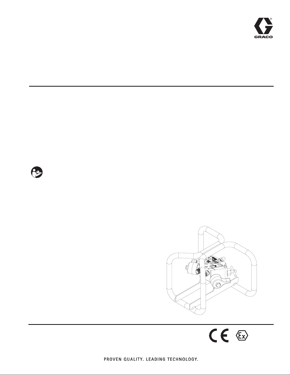
Gun Splitter Valve
Use to operate one or two spray guns with one proportioner or premixed paint in a 1K
sprayer. Provides independent flushing of each gun while the other gun remains in use.
For professional use only.
262826 (includes carriage)
7250 psi (50 MPa, 500 bar) Maximum Material Working Pressure
5000 psi (35 MPa, 345 bar) Maximum Flush Inlet Working Pressure
EN
Important Safety Instructions
Read all warnings and instructions in this
manual. Save these instructions.
II 2 G
c IIB T5
Page 2
Warnings
Contents
Warnings . . . . . . . . . . . . . . . . . . . . . . . . . . . . . . . . . 2
Component Identification . . . . . . . . . . . . . . . . . . . . 4
Pressure Relief Procedure . . . . . . . . . . . . . . . . . . . 5
Installation . . . . . . . . . . . . . . . . . . . . . . . . . . . . . . . . 6
Operation . . . . . . . . . . . . . . . . . . . . . . . . . . . . . . . . . 6
Flushing . . . . . . . . . . . . . . . . . . . . . . . . . . . . . . . . . . 6
Parts . . . . . . . . . . . . . . . . . . . . . . . . . . . . . . . . . . . . . 8
Technical Data . . . . . . . . . . . . . . . . . . . . . . . . . . . . 10
Graco Standard Warranty . . . . . . . . . . . . . . . . . . . 12
Warnings
The following warnings are for the setup, use, grounding, maintenance, and repair of this equipment. The exclamation point symbol alerts you to a general warning and the hazard symbols refer to procedure-specific risks. When
these symbols appear in the body of this manual or on warning labels, refer back to these Warnings. Product-specific
hazard symbols and warnings not covered in this section may appear throughout the body of this manual where
applicable.
WARNING
FIRE AND EXPLOSION HAZARD
Flammable fumes, such as solvent and paint fumes, in work area can ignite or explode. To help prevent
fire and explosion:
• Use equipment only in well ventilated area.
• Eliminate all ignition sources; such as pilot lights, cigarettes, portable electric lamps, and plastic
drop cloths (potential static arc).
• Keep work area free of debris, including solvent, rags and gasoline.
• Do not plug or unplug power cords, or turn power or light switches on or off when flammable fumes
are present.
• Ground all equipment in the work area. See Grounding instructions.
• Use only grounded hoses.
• Hold gun firmly to side of grounded pail when triggering into pail. Do not use pail liners unless they
are antistatic or conductive.
• Stop operation immediately if static sparking occurs or you feel a shock. Do not use equipment
until you identify and correct the problem.
• Keep a working fire extinguisher in the work area.
SKIN INJECTION HAZARD
High-pressure fluid from gun, hose leaks, or ruptured components will pierce skin. This may look like
just a cut, but it is a serious injury that can result in amputation. Get immediate surgical treatment.
• Do not spray without tip guard and trigger guard installed.
• Engage trigger lock when not spraying.
• Do not point gun at anyone or at any part of the body.
• Do not put your hand over the spray tip.
• Do not stop or deflect leaks with your hand, body, glove, or rag.
• Follow the Pressure Relief Procedure when you stop spraying and before cleaning, checking, or
servicing equipment.
• Tighten all fluid connections before operating the equipment.
• Check hoses and couplings daily. Replace worn or damaged parts immediately.
2 3A2573D
Page 3
Warnings
WARNING
TOXIC FLUID OR FUMES HAZARD
Toxic fluids or fumes can cause serious injury or death if splashed in the eyes or on skin, inhaled, or
swallowed.
• Read MSDSs to know the specific hazards of the fluids you are using.
• Store hazardous fluid in approved containers, and dispose of it according to applicable guidelines.
PRESSURIZED ALUMINUM PARTS HAZARD
Use of fluids that are incompatible with aluminum in pressurized equipment can cause serious
chemical reaction and equipment rupture. Failure to follow this warning can result in death, serious
injury, or property damage.
• Do not use 1,1,1-trichloroethane, methylene chloride, other halogenated hydrocarbon solvents or
fluids containing such solvents.
• Many other fluids may contain chemicals that can react with aluminum. Contact your material
supplier for compatibility.
PERSONAL PROTECTIVE EQUIPMENT
Wear appropriate protective equipment when in the work area to help prevent serious injury, including
eye injury, hearing loss, inhalation of toxic fumes, and burns. This protective equipment includes but is
not limited to:
• Protective eyewear, and hearing protection.
• Respirators, protective clothing, and gloves as recommended by the fluid and solvent manufacturer.
EQUIPMENT MISUSE HAZARD
Misuse can cause death or serious injury.
• Do not operate the unit when fatigued or under the influence of drugs or alcohol.
• Do not exceed the maximum working pressure or temperature rating of the lowest rated system
component. See Technical Data in all equipment manuals.
• Use fluids and solvents that are compatible with equipment wetted parts. See Technical Data in all
equipment manuals. Read fluid and solvent manufacturer’s warnings. For complete information
about your material, request MSDS from distributor or retailer.
• Do not leave the work area while equipment is energized or under pressure.
• Turn off all equipment and follow the Pressure Relief Procedure when equipment is not in use.
• Check equipment daily. Repair or replace worn or damaged parts immediately with genuine manufacturer’s replacement parts only.
• Do not alter or modify equipment. Alterations or modifications may void agency approvals and create safety hazards.
• Make sure all equipment is rated and approved for the environment in which you are using it.
• Use equipment only for its intended purpose. Call your distributor for information.
• Route hoses and cables away from traffic areas, sharp edges, moving parts, and hot surfaces.
• Do not kink or over bend hoses or use hoses to pull equipment.
• Keep children and animals away from work area.
• Comply with all applicable safety regulations.
3A2573D 3
Page 4
Component Identification
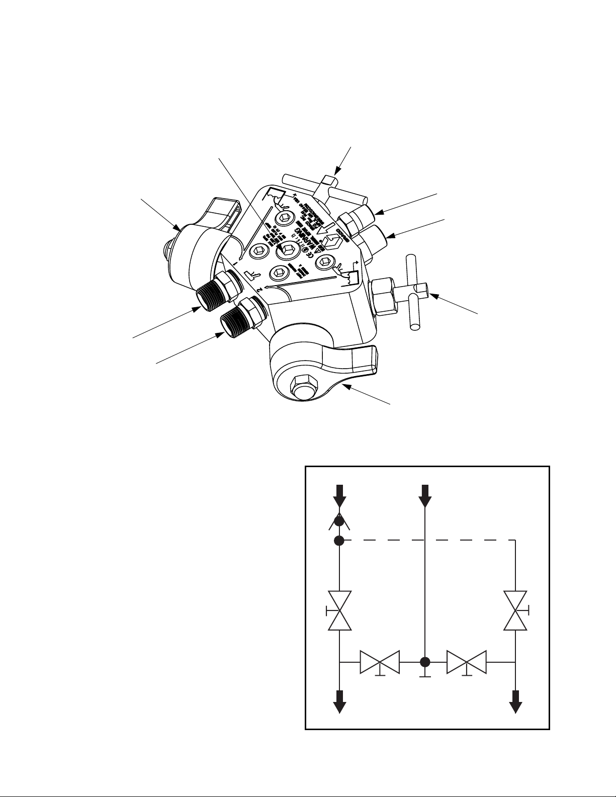
Component Identification
J
B
A
H
G
Key:
A Gun #1 Material Shutoff Valve
B Gun #1 Solvent Shutoff Valve
C Solvent Inlet Port
D Mixed Material Inlet Port
E Gun #2 Solvent Shutoff Valve
F Gun #2 Material Shutoff Valve
G Gun #2 Outlet Port
H Gun #1 Outlet Port
J Optional Mixed Material Through Port For Third Gun
K Solvent Check Valve
C/K
D
E
F
Schematic View
C
K
D
NOTE: The Optional Mixed Material Through Port (J)
can be used for a third gun.
EB
AFJ
H
4 3A2573D
G
Page 5

Pressure Relief Procedure
Pressure Relief Procedure
Follow the Pressure Relief Procedure whenever
you see this symbol.
This equipment stays pressurized until pressure is
manually relieved. To help prevent serious injury from
pressurized fluid, such as skin injection, splashing
fluid and moving parts, follow the Pressure Relief
Procedure when you stop spraying and before
cleaning, checking, or servicing the equipment.
Relieve A and B Fluid Pressure
1. Engage the trigger lock.
TI1949a
2. Close the main air shutoff valve (CA) on your proportioner pump or 1K sprayer.
7. Disengage the trigger lock.
TI1950a
TI1953a
8. Hold a metal part of the gun firmly to a grounded
metal pail. Trigger the gun to relieve pressure.
9. Engage the trigger lock.
10. If you are using a XP Sprayer, close the dual shutoff
handle (AE) and open the circulation handle (AC).
AC
AE
CA
r_571100_3A0420A_11a-1
3. Shut off heaters, if used.
4. Shut off feed pumps, if used.
5. Open gun #1 and gun #2 material shutoff valves (A,
F).
A - OPEN F - OPEN
6. Remove the spray tip and clean.
r_571101_3A0420A_9a-2
11. Always flush the mix hose after relieving A and B
fluid pressure through the mix manifold. See Flush
Mixed Material instructions in XP Sprayer manual.
12. Shutoff the solvent supply pump and repeat steps
6-8 to relieve solvent pressure. Ensure solvent
valves (B, E) are open.
B - OPENE - OPEN
If you are using a XP Sprayer and the mixed material
has already been flushed, but pressure remains on
the A and B pumps, pressure can be relieved back
to the hoppers.
a. Close the main air shutoff valve (CA).
b. Open the circulation handle (AC).
3A2573D 5
Page 6

Installation
Installation
1. Connect the mixed material supply line from the proportioner or 1K sprayer to the manifold material inlet
port (D).
2. Connect a hose between each manifold gun material outlet (G,H) and spray gun fluid inlet.
3. Connect a solvent supply hose from the solvent supply to the manifold solvent inlet port (C).
Operation
NOTICE
Do not allow mixed material to reside in equipment
longer than the pot life of the material at fluid temperature. Pot life is much shorter than dry time.
Heated material cures much faster than ambient
and may damage your equipment. Check your
material safety data sheet (MSDS).
Flushing
The gun splitter valve can flush both guns at the same
time or flush one gun independently while the other gun
continues to spray. The equipment must be flushed if:
• Any gun will not be used within the pot life of the
material.
• Neither gun will be used within the pot life of the
material. The mixed feed line, splitter, and both guns
must be flushed.
To reduce the risk of skin injection, follow the
Pressure Relief Procedure in your proportioner or 1K
sprayer manual when you stop spraying and before
cleaning, checking, servicing, or transporting
equipment.
Depending on which gun you want to supply material to,
open the material shutoff valve for gun #1 (A), gun #2
(F), or both valves.
A - OPEN F - OPEN
To shut off material supply to a gun, close the material
shutoff valve (A or F).
A - CLOSE
F - CLOSE
1. Close the material shutoff valves gun #1 (A) or gun
#2 (F) for the gun to be flushed.
2. Relieve material pressure in the gun to be flushed
by unlocking the trigger lock. Trigger the gun into a
grounded pail. Lock trigger lock.
Unlocked
3. Lock trigger lock. Remove spray tip.
Locked
Locked
TI1948A
4. Turn on solvent supply and set the pressure as
needed for flushing.
6 3A2573D
Page 7

5. Open the gun’s solvent flush valve for gun #1 (B) or
gun #2 (E).
B - OPENE - OPEN
6. Unlock trigger lock and trigger gun into a grounded
pail. Flush out mixed material until clean solvent dispenses. Lock trigger lock.
Flushing
Unlocked
Locked
7. Shutoff solvent pump and close solvent valve for
gun #1 (B) or gun #2 (E).
B - CLOSEE - CLOSE
8. Lock trigger lock.
Locked
9. Final Flush must be done from the proportioner’s
mix manifold or while flushing your pre-mix sprayer,
through the gun splitter to the gun. Follow Flushing
procedure in your proportioner or sprayer manual.
NOTE: It is good practice to flush through each individual flush line valve after flushing through the main inlet.
3A2573D 7
Page 8

Parts
Parts
262826, Gun Splitter Valve
18
17
15
1
29
3 4
19 (x5)
23
14
3 4
20
13
5
2
12
13
5
12
2
21
25
1
1
2
ti19051a
11
1
Apply PTFE thread sealant to fittings.
2
Apply lubricant to o-rings.
3
Prior to assembly, turn valves counter-clockwise to the fully
open position. Torque valve into body (11) to 50 +/- 5 ft-lbs (67.7
N•m).
Ref. Part Description Qty.
1 --- VALVE, splitter
(includes items 11-29)
2 262816 CARRIAGE, remote valve 1
3 100214 WASHER, lock 3
4 558673 SCREW, shcs, 5/16-18 x 3/4 in. (19
mm)
11 262822
12* 195136
13* 195132
14 24M220
BODY, splitter, gun
O-RING, PTFE
SEAT, carbide
CARTRIDGE, valve, solvent;
see page 9
15 24M219
CARTRIDGE, valve, paint;
see page 9
3
4
4
4
Apply thread locker to external threads.
5
When replacing the seat, torque the stem to the seat five times,
up to 80 in-lbs (9 N•m), to form sealing surface.
Ref. Part Description Qty.
17 15R381
1
18 117623
19 100721
20 563210
3
21 156971
1
23 101754
4
25 159239
4
29 156849
2
* Included in Valve Seal Repair Kit 24M213 (purchase
2
separately). See 24M213, Valve Seal Repair Kit,
HANDLE, black
NUT, cap, 3/8-16
PLUG, pipe, 1/4 npt
VALVE, check, 1/4 npt, 5000 psi
(35 MPa, 345 bar)
FITTING, nipple, short; 1/4 npt
PLUG, pipe; 3/8 npt
FITTING, nipple, pipe, reducing
PIPE, nipple; 3/8 npt
page 9.
2
2
5
1
1
1
2
2
8 3A2573D
Page 9

24M220, Solvent Valve 24M219, Material Valve
46
36
46
36
52
1
1 3
3
2
4
46
43
41
51
1
4
36
33
50
3
2
4
ti19127b
51
31
1
3
1
4
50
52
ti19126b
Parts
1
1
Install seal with assembly tools 15T630 and 16T066 from valve seal repair kit.
2
Prior to installing the shutoff valve, apply medium strength thread locker to threads and allow to cure.
3
Apply lubricant to seal, threads and o-ring.
4
Torque to 130 in-lbs (15 N•m).
Ref. Part Description Qty.
31* 15M529 SEAL, check valve 1
33* 16M186 VALVE, shut off, splitter, gun 1
13 195132 SEAT, carbide 1
12 195136 O-RING, PTFE 1
36 24M212 CARTRIDGE, valve, solvent 1
Ref. Part Description Qty.
41* 15M529 SEAL, check valve 1
43* 16M186 VALVE, shut off, splitter, gun 1
13 195132 SEAT, carbide 1
12 195136 O-RING, PTFE 1
46 24M211 CARTRIDGE, valve, paint 1
* Included in Valve Seal Repair Kit 24M213 (purchase separately).
24M213, Valve Seal Repair Kit
Ref. Part Description Qty.
12 195136
13 195132
31, 41 15M529
33, 43 16M186
50 15Y627
51 15T630
52 16T066
O-RING, PTFE
SEAT, carbide
SEAL, check valve
VALVE, shut off, splitter, gun
PACKING, o-ring #2-116, PTFE
TOOL, seal assembly
TOOL, seal assembly
1
1
1
1
1
1
1
3A2573D 9
Page 10

Technical Data
Technical Data
Gun Splitter Valve
US Metric
Maximum fluid working pressure
Mixed paint
Flush solvent
Paint wetted materials
Manifold and valve housings Nickel plated steel
Seats Carbide
Valve stems 17-4 and 440c stainless
Seals PTFE, UHMWPE
Solvent flush wetted materials
Check valve and fittings Zinc plated steel
Ball Chrome alloy
Gasket Aluminum
Connections
Mixed paint inlet 1/2 in. npt(f) port with 3/8 npt(m) inlet
Flush solvent inlet 1/4 in. npt(m) nipple
Gun 1 and Gun 2 outlets 3/8 npt nipples in 3/8 npt(f) ports
Optional Gun 3 straight through outlet 3/8 npt(f) plugged port
Weight
Gun splitter valve with carriage 10.2 lbs 4.6 kg
Carriage Dimensions
Height 8 in. 20.3 cm
Width 6.25 in. 15.87 cm
Length 9.26 in. 23.52 cm
7250 psi 50 Mpa, 500 bar
5000 psi 35 MPa, 345 bar
10 3A2573D
Page 11

Technical Data
3A2573D 11
Page 12

Graco Standard Warranty
Graco warrants all equipment referenced in this document which is manufactured by Graco and bearing its name to be free from defects in
material and workmanship on the date of sale to the original purchaser for use. With the exception of any special, extended, or limited warranty
published by Graco, Graco will, for a period of twelve months from the date of sale, repair or replace any part of the equipment determined by
Graco to be defective. This warranty applies only when the equipment is installed, operated and maintained in accordance with Graco’s written
recommendations.
This warranty does not cover, and Graco shall not be liable for general wear and tear, or any malfunction, damage or wear caused by faulty
installation, misapplication, abrasion, corrosion, inadequate or improper maintenance, negligence, accident, tampering, or substitution of
non-Graco component parts. Nor shall Graco be liable for malfunction, damage or wear caused by the incompatibility of Graco equipment with
structures, accessories, equipment or materials not supplied by Graco, or the improper design, manufacture, installation, operation or
maintenance of structures, accessories, equipment or materials not supplied by Graco.
This warranty is conditioned upon the prepaid return of the equipment claimed to be defective to an authorized Graco distributor for verification of
the claimed defect. If the claimed defect is verified, Graco will repair or replace free of charge any defective par ts. The equipment will be returned
to the original purchaser transportation prepaid. If inspection of the equipment does not disclose any defect in material or workmanship, repairs will
be made at a reasonable charge, which charges may include the costs of parts, labor, and transportation.
THIS WARRANTY IS EXCLUSIVE, AND IS IN LIEU OF ANY OTHER WARRANTIES, EXPRESS OR IMPLIED, INCLUDING BUT NOT LIMITED
TO WARRANTY OF MERCHANTABILITY OR WARRANTY OF FITNESS FOR A PARTICULAR PURPOSE.
Graco’s sole obligation and buyer’s sole remedy for any breach of warranty shall be as set forth above. The buyer agrees that no other remedy
(including, but not limited to, incidental or consequential damages for lost profits, lost sales, injury to person or property, or any other incidental or
consequential loss) shall be available. Any action for breach of warranty must be brought within two (2) years of the date of sale.
GRACO MAKES NO WARRANTY, AND DISCLAIMS ALL IMPLIED WARRANTIES OF MERCHANTABILITY AND FITNESS FOR A
PARTICULAR PURPOSE, IN CONNECTION WITH ACCESSORIES, EQUIPMENT, MATERIALS OR COMPONENTS SOLD BUT NOT
MANUFACTURED BY GRACO. These items sold, but not manufactured by Graco (such as electric motors, switches, hose, etc.), are subject to
the warranty, if any, of their manufacturer. Graco will provide purchaser with reasonable assistance in making any claim for breach of these
warranties.
In no event will Graco be liable for indirect, incidental, special or consequential damages resulting from Graco supplying equipment hereunder, or
the furnishing, performance, or use of any products or other goods sold hereto, whether due to a breach of contract, breach of warranty, the
negligence of Graco, or otherwise.
FOR GRACO CANADA CUSTOMERS
The Parties acknowledge that they have required that the present document, as well as all documents, notices and legal proceedings entered into,
given or instituted pursuant hereto or relating directly or indirectly hereto, be drawn up in English. Les parties reconnaissent avoir convenu que la
rédaction du présente document sera en Anglais, ainsi que tous documents, avis et procédures judiciaires exécutés, donnés ou intentés, à la suite
de ou en rapport, directement ou indirectement, avec les procédures concernées.
Graco Information
For the latest information about Graco products, visit www.graco.com.
TO PLACE AN ORDER, contact your Graco distributor or call to identify the nearest distributor.
Phone: 612-623-6921 or Toll Free: 1-800-328-0211 Fax: 612-378-3505
All written and visual data contained in this document reflects the latest product information available at the time of publication.
GRACO INC. AND SUBSIDIARIES • P.O. BOX 1441 • MINNEAPOLIS MN 55440-1441 • USA
Copyright 2012, Graco Inc. All Graco manufacturing locations are registered to ISO 9001.
Graco reserves the right to make changes at any time without notice.
For patent information, see www.graco.com/patents.
Original instructions. This manual contains English. MM 3A2573
Graco Headquarters: Minneapolis
International Offices: Belgium, China, Japan, Korea
www.graco.com
Revised October 2014
 Loading...