

Page 1
Instructions-Parts
3A2526F
E-Flo®
E-Flo® E-Flo®
DC
DC DC
Motor
Motor Motor
EN
Electric
Electric Electric
For
For For
See page 3 for model part numbers and
approvals information.
drive
for
low
to
drive drive
for for
low low
professional
professional professional
Important
Important Important
Readallwarningsandinstructionsinthismanual.
Save
Save Save
use
use use
Safety
Safety Safety
these
these these
medium
to to
medium medium
only.
only. only.
Instructions
Instructions Instructions
instructions.
instructions. instructions.
volume
volume volume
paint
circulation
paint paint
circulation circulation
pumps.
pumps. pumps.
PROVENQUALITY.LEADINGTECHNOLOGY.
Page 2

Contents
Contents Contents
Models...............................................................3
BasicModels...............................................3
BasicModelswithRegion-Specic
Approvals.......................................4
AdvancedModels........................................5
AdvancedModelswithRegion-Specic
Approvals.......................................6
Warnings...........................................................7
Installation..........................................................10
FillWithOilBeforeUsingEquipment.............10
PowerSupplyRequirements.........................10
ConnectthePowerSupply...........................11
Grounding...................................................12
IntrinsicallySafeInstallationRequirements
forAdvancedMotors.......................12
Operation...........................................................13
Startup........................................................13
Shutdown....................................................13
PressureReliefProcedure............................13
AdvancedMotorOperation...........................13
BasicMotorOperation..................................14
Maintenance......................................................16
PreventiveMaintenanceSchedule................16
ChangetheOil.............................................16
CheckOilLevel...........................................16
BearingPre-Load.........................................16
ErrorCodeTroubleshooting................................17
Repair................................................................19
ReplaceOutputSealCartridge.....................19
Parts..................................................................20
BasicMotorAssembly..................................20
AdvancedMotorAssembly...........................22
Notes................................................................24
RepairKits,RelatedManuals,and
Accessories..........................................25
ControlBoardReplacementKits24U934,
24U936,24U935,24U937.....................27
Overview.....................................................27
ToolsRequired............................................27
ReplacementInstructions.............................27
EncoderReplacementKit24U938.......................29
Overview.....................................................29
ToolsRequired............................................29
ReplacementInstructions.............................29
PositionSensorReplacementKit16U705............32
Overview.....................................................32
ToolsRequired............................................32
ReplacementInstructions.............................32
AdvancedPowerBoardReplacementKit
24U939................................................34
ToolsRequired............................................34
ReplacementInstructions.............................34
PrepareMotor..............................................34
DisconnectPowerWires...............................34
RemoveControlModuleBracket...................34
RemoveElectronicsCover...........................34
DisconnectPowerBarrierBoard...................35
InstallNewPowerBarrierBoard...................35
ReinstallElectronicsCover...........................35
ReinstallWiringBoxCover...........................35
AttachControlModuleBracket......................36
PowerUnit...................................................36
ReattachPumpLower..................................36
AppendixA-SystemControlDrawing
24N637................................................37
MountingHolePattern........................................42
TechnicalData...................................................43
GracoStandardWarranty....................................44
2
3A2526F
Page 3
Models
Models
Models Models
Basic
Basic Basic
Motor
Motor Motor
EM0011A1
EM0021A2
Models
Models Models
Part
No.
Part Part
No. No.
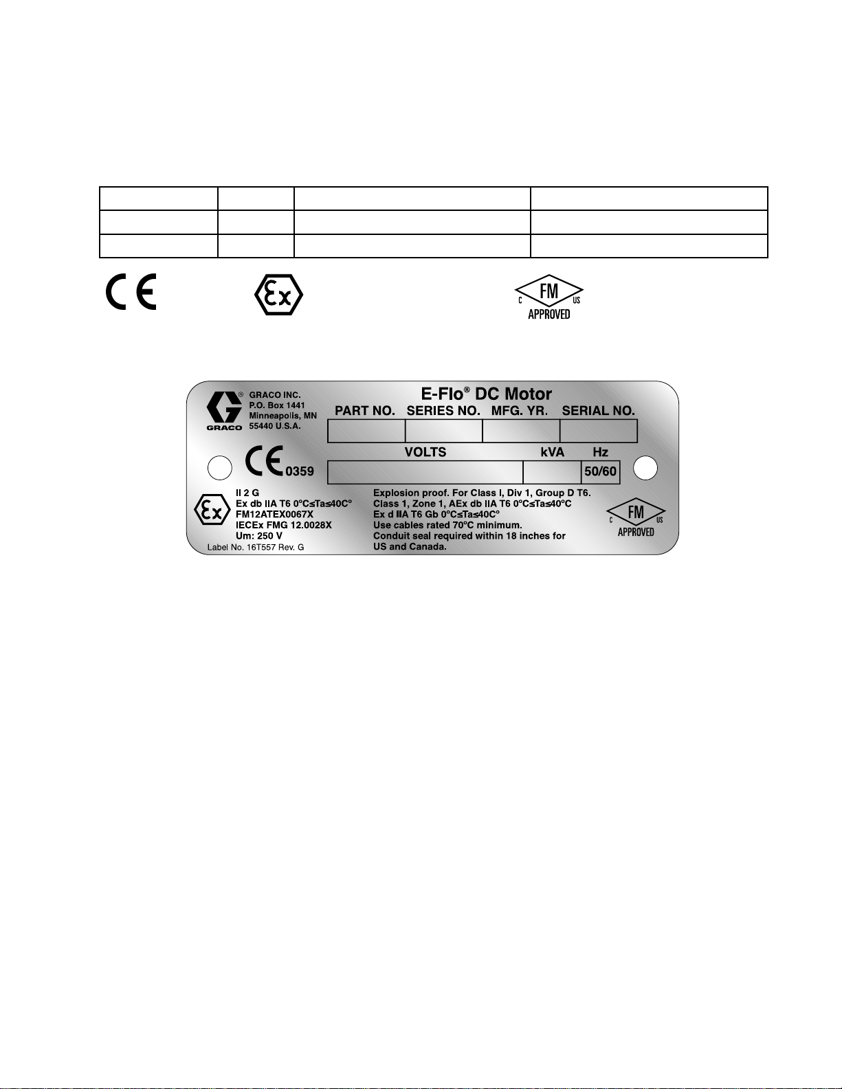
0359
0359 0359
Series
Series Series
ExdbIIAT60°C≤Ta≤40°C
FM12ATEX0067X
IECExFMG12.0028X
Horsepower
Horsepower Horsepower
II2G
Maximum
Maximum Maximum
1400(6227)
2800(12455)
ForClassI,Div.1,GroupDT6.
Class1,Zone1,AExdbIIAT60°C≤Ta≤40°C
ExdIIAT6Gb0°C≤Ta≤40°C
Force,
Force, Force,
lbf
(N)
lbf lbf
(N) (N)
Figure1BasicMotorIdenticationLabel
List
List List
•IEC60079–0:2011(Ed.6)
•IEC60079–1:2007w/Corr1(Ed6)
•EN60079–0:2012
•EN60079–1:2007
•ANSI/ISA60079–0:2009
•ANSI/ISA60079–1:2009
•FM3615:2006
Specic
Specic Specic
1.Consultthemanufacturerifdimensional
2.Consultthemanufacturerforgenuine
Standards
of ofofStandards Standards
Conditions
Conditions Conditions
informationontheameproofjointisnecessary.
replacementfasteners.M8x30socket-head
capscrewsofClass12.9steelorbetterwitha
minimumyieldstrengthof1100MPa(160,000
psi)areacceptablealternatives.
Use:
of ofofUse: Use:
•CSAC22.2No.0.4:2004(R2009)
•CSAC22.2No.0.5:82(R2008)
•CSAC22.2No.30:M86(R2007)
•CAN/CSA-E60079–0:2011
•CAN/CSA-E60079–1:2011
•CAN/CSAC22.2No.1010.1:2004
3A2526F 3
Page 4
Models
Basic
Basic Basic
Motor
Motor Motor
EM0013A1
EM0023A2
Models
Models Models
Part
No.
Part Part
No. No.
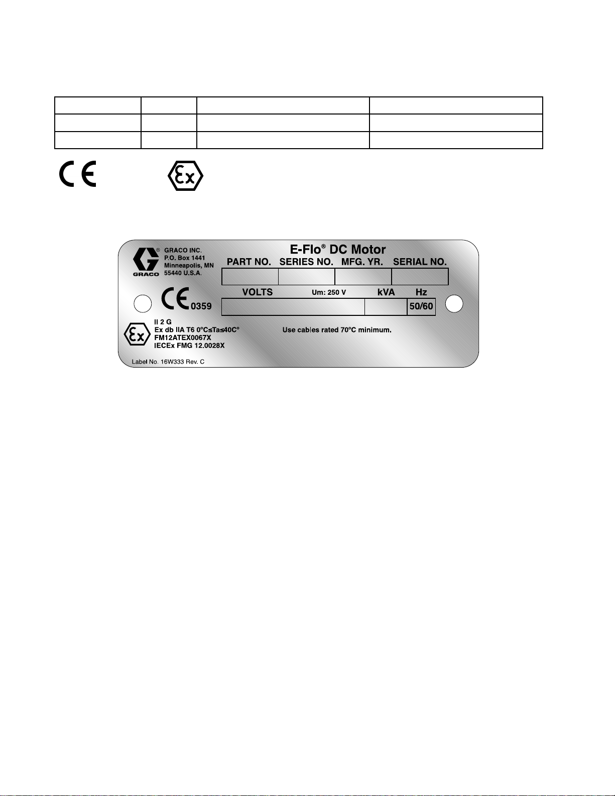
0359
0359 0359
with
Region
with with
Region Region
Series
Series Series
ExdIIAT60°C≤Ta≤40°C
FM12ATEX0067X
IECExFMG12.0028X
Specic
- --Specic Specic
Horsepower
Horsepower Horsepower
II2G
Approvals
Approvals Approvals
Maximum
Maximum Maximum
1400(6227)
2800(12455)
Force,
Force, Force,
lbf
(N)
lbf lbf
(N) (N)
Figure2BasicMotorwithRegion-SpecicApprovals
IdenticationLabel
List
List List
•IEC60079–0:2011(Ed.6)
•IEC60079–1:2007w/Corr1(Ed6)
Specic
Specic Specic
1.Consultthemanufacturerifdimensional
2.Consultthemanufacturerforgenuine
Standards
of ofofStandards Standards
Conditions
Conditions Conditions
informationontheameproofjointisnecessary.
replacementfasteners.M8x30socket-head
capscrewsofClass12.9steelorbetterwitha
minimumyieldstrengthof1100MPa(160,000
psi)areacceptablealternatives.
Use:
of ofofUse: Use:
•EN60079–0:2012
•EN60079–1:2007
4
3A2526F
Page 5
Models
Advanced
Advanced Advanced
Motor
Part
Motor Motor
Part Part
EM0012A1
EM0022A2
EM0025A2
Models
Models Models
No.
No. No.
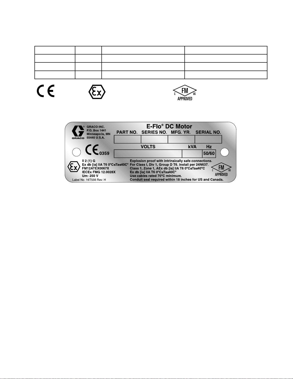
0359
0359 0359
Series
Series Series
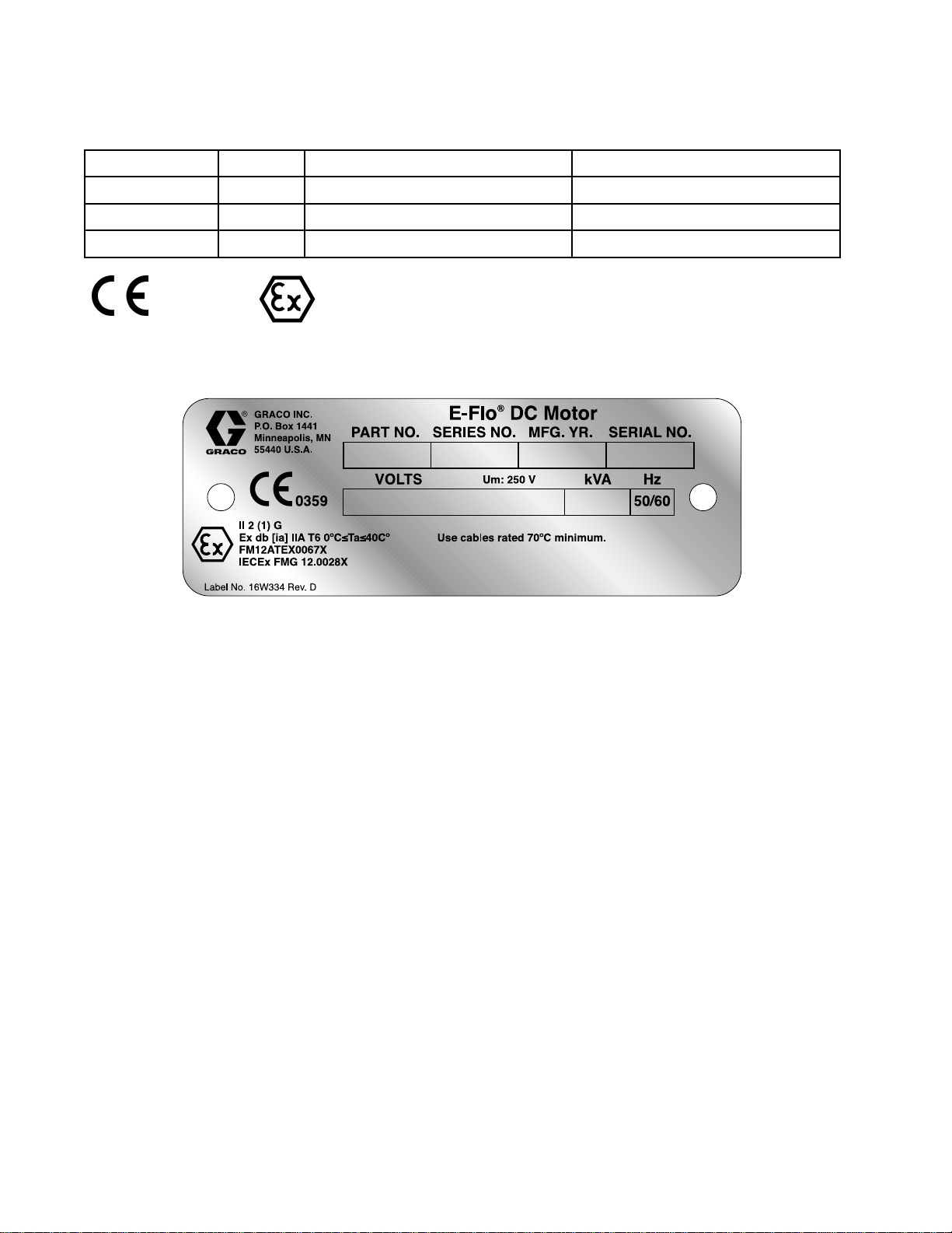
Exdb[ia]IIAT60°C≤Ta≤40°C
FM12ATEX0067X
IECExFMG12.0028X
Horsepower
Horsepower Horsepower
II2(1)G
Maximum
Maximum Maximum
1400(6227)
2800(12455)
2800(12455)
Class1,Zone1,AExdb[ia]IIAT60°C≤Ta≤40°C
Exdb[ia]IIAT60°C≤Ta≤40°C
Force,
Force, Force,
ForClassI,Div.1,GroupDT6.
lbf
(N)
lbf lbf
(N) (N)
Figure3AdvancedMotorIdenticationLabel
List
List List
•IEC60079–0:2011(Ed.6)
•IEC60079–1:2007w/Corr1(Ed.6)
•IEC60079–11:2011(Ed.6)
•EN60079–0:2012
•EN60079–1:2007
•EN60079–11:2012
•FM3600:2011
•FM3610:2010
•FM3615:2006
•FM3810:2005
•CSAC22.2No.0.4:2004(R2009)
Specic
Specic Specic
1.Consultthemanufacturerifdimensional
2.Consultthemanufacturerforgenuine
Standards
of ofofStandards Standards
Conditions
Conditions Conditions
informationontheameproofjointisnecessary.
replacementfasteners.M8x30socket-head
capscrewsofClass12.9steelorbetterwitha
minimumyieldstrengthof1100MPa(160,000
psi)areacceptablealternatives.
Use:
of ofofUse: Use:
•CSAC22.2No.0.5:82(R2008)
•CSAC22.2No.30:M86(R2007)
•CSAC22.2No.157–92(R2006)
•CAN/CSA-E60079–0:2011
•CAN/CSA-E60079–1:2011
•CAN/CSAC22.2No.1010.1:2004
•CAN/CSA-E60079–11:2011
•ANSI/ISA60079–0:2009
•ANSI/ISA60079–1:2009
•ANSI/ISA60079–11:2011
3A2526F 5
Page 6
Models
Advanced
Advanced Advanced
Motor
Part
Motor Motor
Part Part
EM0014A1
EM0024A2
EM0026A2
Models
Models Models
No.
No. No.
0359
0359 0359
with
with with
Series
Series Series
Exd[ia]IIAT60°C≤Ta≤40°C
FM12ATEX0067X
IECExFMG12.0028X
Region
Region Region
Horsepower
Horsepower Horsepower
II2(1)G
Specic
- --Specic Specic
Approvals
Approvals Approvals
Maximum
Maximum Maximum
1400(6227)
2800(12455)
2800(12455)
Force,
Force, Force,
lbf
(N)
lbf lbf
(N) (N)
Figure4AdvancedMotorwithRegion-Specic
ApprovalsIdenticationLabel
List
List List
•IEC60079–0:2011(Ed.6)
•IEC60079–1:2007w/Corr1(Ed.6)
•IEC60079–11:2011(Ed.6)
Specic
Specic Specic
1.Consultthemanufacturerifdimensional
2.Consultthemanufacturerforgenuine
Standards
of ofofStandards Standards
Conditions
Conditions Conditions
informationontheameproofjointisnecessary.
replacementfasteners.M8x30socket-head
capscrewsofClass12.9steelorbetterwitha
minimumyieldstrengthof1100MPa(160,000
psi)areacceptablealternatives.
Use:
of ofofUse: Use:
•EN60079–0:2012
•EN60079–1:2007
•EN60079–11:2012
6 3A2526F
Page 7
Warnings
Warnings Warnings
Thefollowingwarningsareforthesetup,use,grounding,maintenance,andrepairofthisequipment.The
exclamationpointsymbolalertsyoutoageneralwarningandthehazardsymbolsrefertoprocedure-specic
risks.Whenthesesymbolsappearinthebodyofthismanualoronwarninglabels,referbacktothese
Warnings.Product-specichazardsymbolsandwarningsnotcoveredinthissectionmayappearthroughout
thebodyofthismanualwhereapplicable.
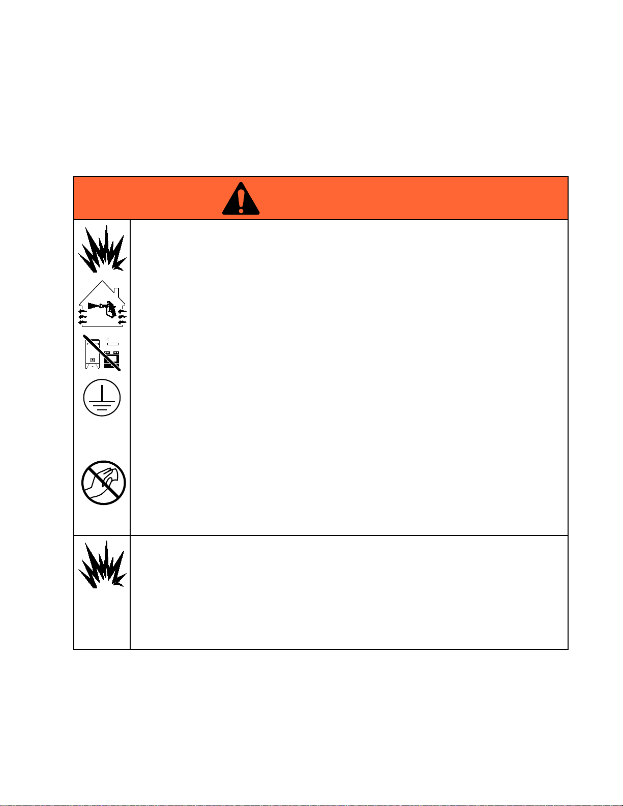
WARNING
WARNING WARNING
FIRE
AND
FIRE FIRE
Flammablefumes,suchassolventandpaintfumes,inwork work
preventreandexplosion:
•Useequipmentonlyinwellventilatedarea.
•Eliminateallignitionsources;suchaspilotlights,cigarettes,portableelectriclamps,and
plasticdropcloths(potentialstaticarc).
•Keepworkareafreeofdebris,includingsolvent,ragsandgasoline.
•Donotplugorunplugpowercords,orturnpowerorlightswitchesonoroffwhenammable
fumesarepresent.
•Groundallequipmentintheworkarea.SeeGrounding Grounding
•Useonlygroundedhoses.
•Holdgunrmlytosideofgroundedpailwhentriggeringintopail.Donotusepaillinersunless
theyareantistaticorconductive.
Stop
•Stop Stop
equipmentuntilyouidentifyandcorrecttheproblem.
•Keepaworkingreextinguisherintheworkarea.
EXPLOSION
AND AND
EXPLOSION EXPLOSION
operation
operation operation
immediately
immediately immediately
HAZARD
HAZARD HAZARD
work
area
area area
canigniteorexplode.Tohelp
Grounding
ifstaticsparkingoccursoryoufeelashock,Donotuse
instructions.
Warnings
Staticchargemaybuilduponplasticpartsduringcleaningandcoulddischargeandignite
ammablevapors.Tohelppreventreandexplosion:
•Cleanplasticpartsonlyinwellventilatedarea.
•Donotcleanwithadrycloth.
•Donotoperateelectrostaticgunsinequipmentworkarea.
SPECIAL
SPECIAL SPECIAL
•Topreventtheriskofelectrostaticsparking,theequipment’snon-metallicpartsshouldbe
cleanedonlywithadampcloth.
•Thealuminumhousingmaysparkuponimpactorcontactwithmovingparts,whichmay
causereorexplosion.Takeprecautionstoavoidsuchimpactorcontact.
•Allameproofjointsarecriticaltotheintegrityofthemotorasapprovedforhazardous
locationsandarenotrepairableifdamaged.Damagedpartsmustbereplacedonlywith
genuineGracopartswithnosubstitutions.
CONDITIONS
CONDITIONS CONDITIONS
FOR
SAFE
FOR FOR
USE
SAFE SAFE
USE USE
3A2526F
7
Page 8
Warnings
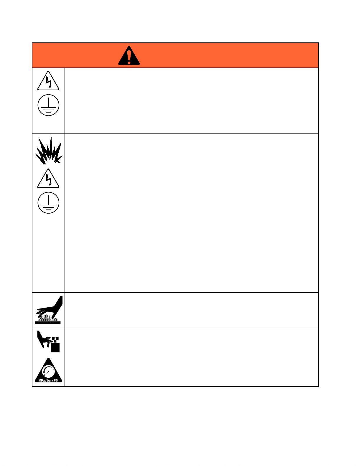
WARNING
WARNING WARNING
ELECTRIC
ELECTRIC ELECTRIC
Thisequipmentmustbegrounded.Impropergrounding,setup,orusageofthesystemcan
causeelectricshock.
•Turnoffanddisconnectpoweratmainswitchbeforedisconnectinganycablesandbefore
servicingorinstallingequipment.
•Connectonlytogroundedpowersource.
•Allelectricalwiringmustbedonebyaqualiedelectricianandcomplywithalllocalcodes
andregulations.
INTRINSIC
INTRINSIC INTRINSIC
Intrinsicallysafeequipmentthatisinstalledimproperlyorconnectedtonon-intrinsicallysafe
equipmentwillcreateahazardousconditionandcancausere,explosion,orelectricshock.
Followlocalregulationsandthefollowingsafetyrequirements.
•Besureyourinstallationcomplieswithnational,state,andlocalcodesfortheinstallationof
electricalapparatusinaClassI,GroupD,Division1HazardousLocation,includingallofthe
localsafetyrecodes,NFPA33,NEC500and516,andOSHA1910.107.
•Equipmentthatcomesincontactwiththeequipment’sintrinsicallysafeterminalsmust
meettheentityparameterrequirementsspeciedinControlDrawing24N637.See
IntrinsicallySafeInstallationRequirementsforAdvancedMotors,page12.Thisincludes
safetybarriers,DCvoltagemeters,ohmmeters,cables,andconnections.Removetheunit
fromthehazardousareawhentroubleshooting.
SHOCK
SHOCK SHOCK
SAFETY
SAFETY SAFETY
HAZARD
HAZARD HAZARD
•Donotinstallanyequipmentapprovedonlyforanon-hazardouslocationinahazardous
area,asdenedinArticle500oftheNationalElectricalCode(USA)oryourlocalelectrical
code.SeetheIDlabelfortheintrinsicsafetyratingforyourequipment.
•Groundthemotor.Usea12gaugeminimumgroundwire,connectedtoatrueearthground.
SeeGrounding,page12.
•Donotoperatethemotorwithanycoverremoved.
•Donotsubstitutesystemcomponents,asthismayimpairintrinsicsafety.
BURN
BURN BURN
Equipmentsurfacesanduidthat’sheatedcanbecomeveryhotduringoperation.Toavoid
severeburns:
•Donottouchhotuidorequipment.
MOVING
MOVING MOVING
Movingpartscanpinch,cutoramputatengersandotherbodyparts.
•Keepclearofmovingparts.
•Donotoperateequipmentwithprotectiveguardsorcoversremoved.
•Pressurizedequipmentcanstartwithoutwarning.Beforechecking,moving,orservicing
HAZARD
HAZARD HAZARD
PARTS
PARTS PARTS
equipment,followthePressure Pressure
HAZARD
HAZARD HAZARD
Pressure
Relief
Procedure
Relief Relief
Procedure Procedure
anddisconnectallpowersources.
8 3A2526F
Page 9
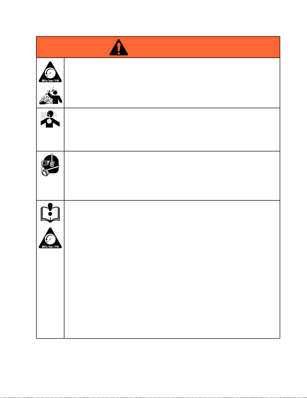
WARNING
WARNING WARNING
PRESSURIZED
PRESSURIZED PRESSURIZED
Fluidfromtheequipment,leaks,orrupturedcomponentscansplashintheeyesoronskin
andcauseseriousinjury.
EQUIPMENT
EQUIPMENT EQUIPMENT
HAZARD
HAZARD HAZARD
Warnings
•FollowthePressure Pressure
cleaning,checking,orservicingequipment.
•Tightenalluidconnectionsbeforeoperatingtheequipment.
•Checkhoses,tubes,andcouplingsdaily.Replacewornordamagedpartsimmediately.
TOXIC
TOXIC TOXIC
Toxicuidsorfumescancauseseriousinjuryordeathifsplashedintheeyesoronskin,
inhaled,orswallowed.
•ReadMSDSstoknowthespecichazardsoftheuidsyouareusing.
•Storehazardousuidinapprovedcontainers,anddisposeofitaccordingtoapplicable
guidelines.
PERSONAL
PERSONAL PERSONAL
Wearappropriateprotectiveequipmentwhenintheworkareatohelppreventseriousinjury,
includingeyeinjury,hearingloss,inhalationoftoxicfumes,andburns.Thisequipmentincludes
butisnotlimitedto:
•Protectiveeyewear,andhearingprotection.
•Respirators,protectiveclothing,andglovesasrecommendedbytheuidandsolvent
manufacturer.
EQUIPMENT
EQUIPMENT EQUIPMENT
Misusecancausedeathorseriousinjury.
•Donotoperatetheunitwhenfatiguedorundertheinuenceofdrugsoralcohol.
•Donotexceedthemaximumworkingpressureortemperatureratingofthelowestrated
systemcomponent.SeeTechnical Technical
•Useuidsandsolventsthatarecompatiblewithequipmentwettedparts.SeeTechnical Technical
inallequipmentmanuals.Readuidandsolventmanufacturer’swarnings.Forcomplete
informationaboutyourmaterial,requestMSDSfromdistributororretailer.
•Donotleavetheworkareawhileequipmentisenergizedorunderpressure.
•TurnoffallequipmentandfollowthePressure Pressure
•Checkequipmentdaily.Repairorreplacewornordamagedpartsimmediatelywithgenuine
manufacturer’sreplacementpartsonly.
•Donotalterormodifyequipment.Alterationsormodicationsmayvoidagencyapprovals
andcreatesafetyhazards.
•Makesureallequipmentisratedandapprovedfortheenvironmentinwhichyouareusingit.
•Useequipmentonlyforitsintendedpurpose.Callyourdistributorforinformation.
•Routehosesandcablesawayfromtrafcareas,sharpedges,movingparts,andhotsurfaces.
•Donotkinkoroverbendhosesorusehosestopullequipment.
•Keepchildrenandanimalsawayfromworkarea.
•Complywithallapplicablesafetyregulations.
Pressure
FLUID
FLUID FLUID
OR
OR OR
PROTECTIVE
PROTECTIVE PROTECTIVE
MISUSE
MISUSE MISUSE
Relief
Procedure
Relief Relief
Procedure Procedure
FUMES
FUMES FUMES
EQUIPMENT
EQUIPMENT EQUIPMENT
HAZARD
HAZARD HAZARD
Technical
whenyoustopspraying/dispensingandbefore
Data
Data Data
inallequipmentmanuals.
Pressure
Relief
Procedure
Relief Relief
Procedure Procedure
whenequipmentisnotinuse.
Technical
Data
Data Data
3A2526F 9
Page 10
Installation
Installation
Installation Installation
Installationofthisequipmentinvolvespotentially
hazardousprocedures.Onlytrainedandqualied
personnelwhohavereadandwhounderstand
theinformationinthismanualshouldinstallthis
equipment.
NOTE:
NOTE: NOTE:
IntrinsicallySafeInstallationRequirementsfor
AdvancedMotors,page12.
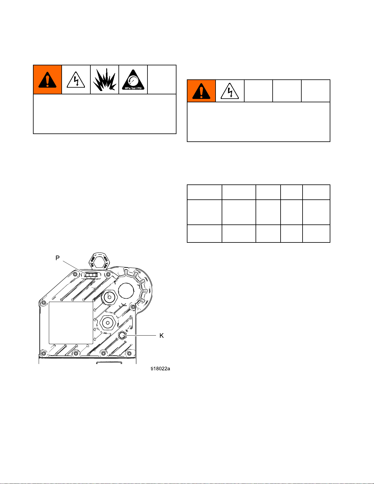
Fill
Fill Fill
Beforeusingtheequipment,openthellcap(P)and
addGracoPartNo.16W645ISO220silicone-free
syntheticgearoil.Checktheoillevelinthesightglass
(K).Filluntiltheoillevelisnearthehalfwaypointof
thesightglass.Theoilcapacityisapproximately1.5
quarts(1.4liters).Do Do
NOTE:
NOTE: NOTE:
suppliedwiththeequipment.
Toinstallanadvancedmotor,alsosee
With
With With
Oil
Before
Oil Oil
Before Before
Do
Two1quart(0.95liter)bottlesofoilare
Using
Using Using
not
overll.
not not
overll. overll.
Equipment
Equipment Equipment
Power
Power Power
Improperwiringmaycauseelectricshockorother
seriousinjuryifworkisnotperformedproperly.
Haveaqualiedelectricianperformanyelectrical
work.Besureyourinstallationcomplieswithall
National,StateandLocalsafetyandrecodes.
SeeTable1forpowersupplyrequirements.The
systemrequiresadedicatedcircuitprotectedwitha
circuitbreaker.
Table
Table Table
Model*
Model* Model*
EM001x100–130
EM002x200–240
*ThelastdigitoftheModelNo.varies.Seethe
Models
Models Models
Supply
Supply Supply
Power
1 11. ..Power Power
Voltage
Voltage Voltage
/200–240
Vac
Vac
tablesonpages3–6.
Requirements
Requirements Requirements
Supply
Supply Supply
Specications
Specications Specications
Phase
Phase Phase
150/601.4
150/602.9
Hz
Hz Hz
kVA
kVA kVA
Figure5SightglassandOilFillCap
Hazardous
Hazardous Hazardous
Requirements
Requirements Requirements
Explosion
Explosion Explosion
Allelectricalwiringinthehazardousareamustbe
encasedinClassI,DivisionI,GroupDapproved
explosion-proofconduit.FollowallNational,State,
andLocalelectriccodes.
Aconduitseal(D)isrequiredwithin18in.(457mm)
ofthemotorfortheUSandCanada.
Allcablesmustberatedat70°C.
Flame
Flame Flame
Useappropriateconduit,connectors,andcable
glandsratedforATEXII2G.FollowallNational,
State,andLocalelectriccodes.
Allcableglandsandcablesmustberatedat70°C.
Area
Cabling
Area Area
Cabling Cabling
Proof
Proof Proof
Proof
Proof Proof
(ATEX)
(ATEX) (ATEX)
and
Conduit
and and
Conduit Conduit
10 3A2526F
Page 11
Installation
Connect
Connect Connect
Improperwiringmaycauseelectricshockorother
seriousinjuryifworkisnotperformedproperly.
Haveaqualiedelectricianperformanyelectrical
work.Besureyourinstallationcomplieswithall
National,StateandLocalsafetyandrecodes.
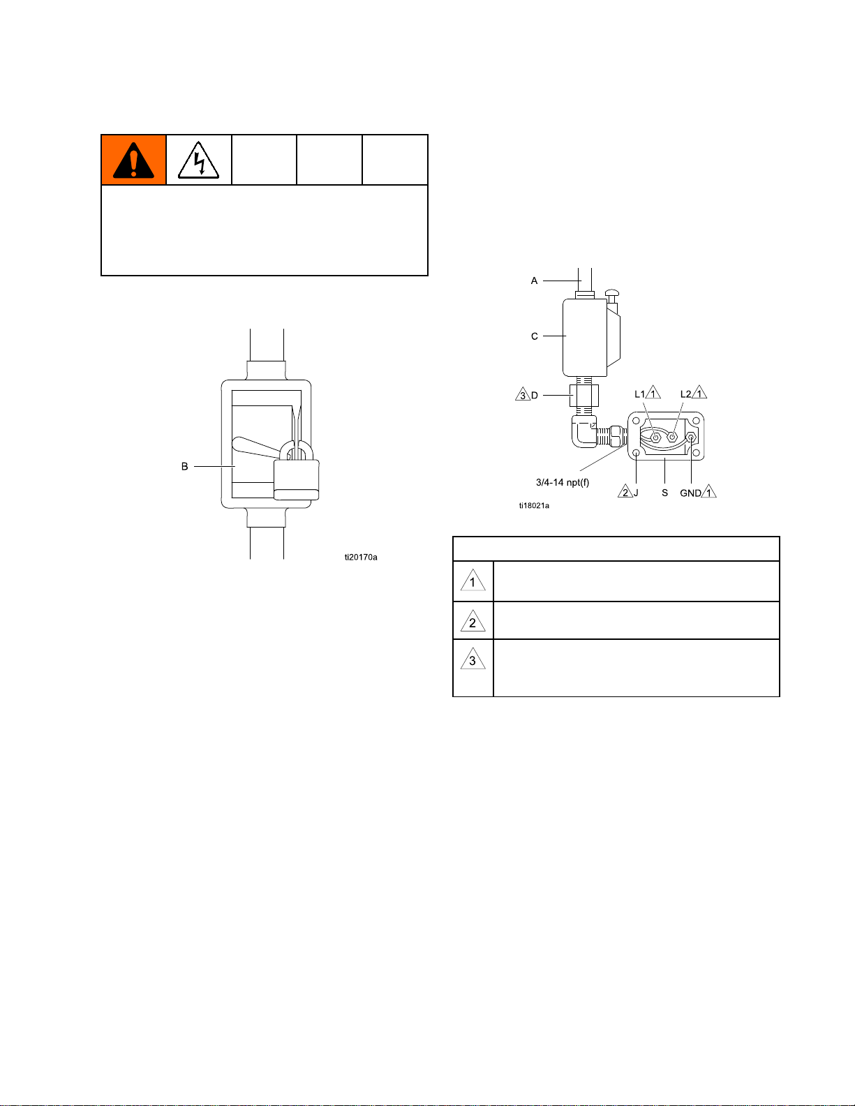
1.Ensurethatthefusedsafetyswitch(B)isshut
offandlockedout.
the
Power
the the
Power Power
Supply
Supply Supply
4.Bringthepowerwiresintotheelectrical
compartmentthroughthe3/4–14npt(f)inletport.
Connectthewirestotheterminals,asshown.
Torquetheterminalnutsto25in-lb(2.8N•m)
Do
not
maximum.Do Do
5.Closetheelectricalcompartment.Torquethe
coverscrews(J)to15ft-lb(20.3N•m).
over-torque.
not not
over-torque. over-torque.
Figure6LockedOutFusedSafetySwitch
2.Installastart/stopcontrol(C)intheelectrical
supplyline(A),withineasyreachofthe
equipment.Thestart/stopcontrolmustbe
approvedforuseinhazardouslocations.
3.Opentheelectricalcompartment(S)onthe
motor.
Figure7ConnectthePowerWires
Notes
for
Fig.
Notes Notes
for for
Tightenallterminalnutsto25in-lb(2.8N•m)
maximum.Do Do
Tightencoverscrewsto15ft-lb(20.3N•m).
Aconduitseal(D)isrequiredwithin18
in.(457mm)ofthemotorfortheUSand
Canada.
7
Fig. Fig.
7 7
Do
not
over
not not
torque.
over over
- --torque. torque.
3A2526F
11
Page 12
Installation
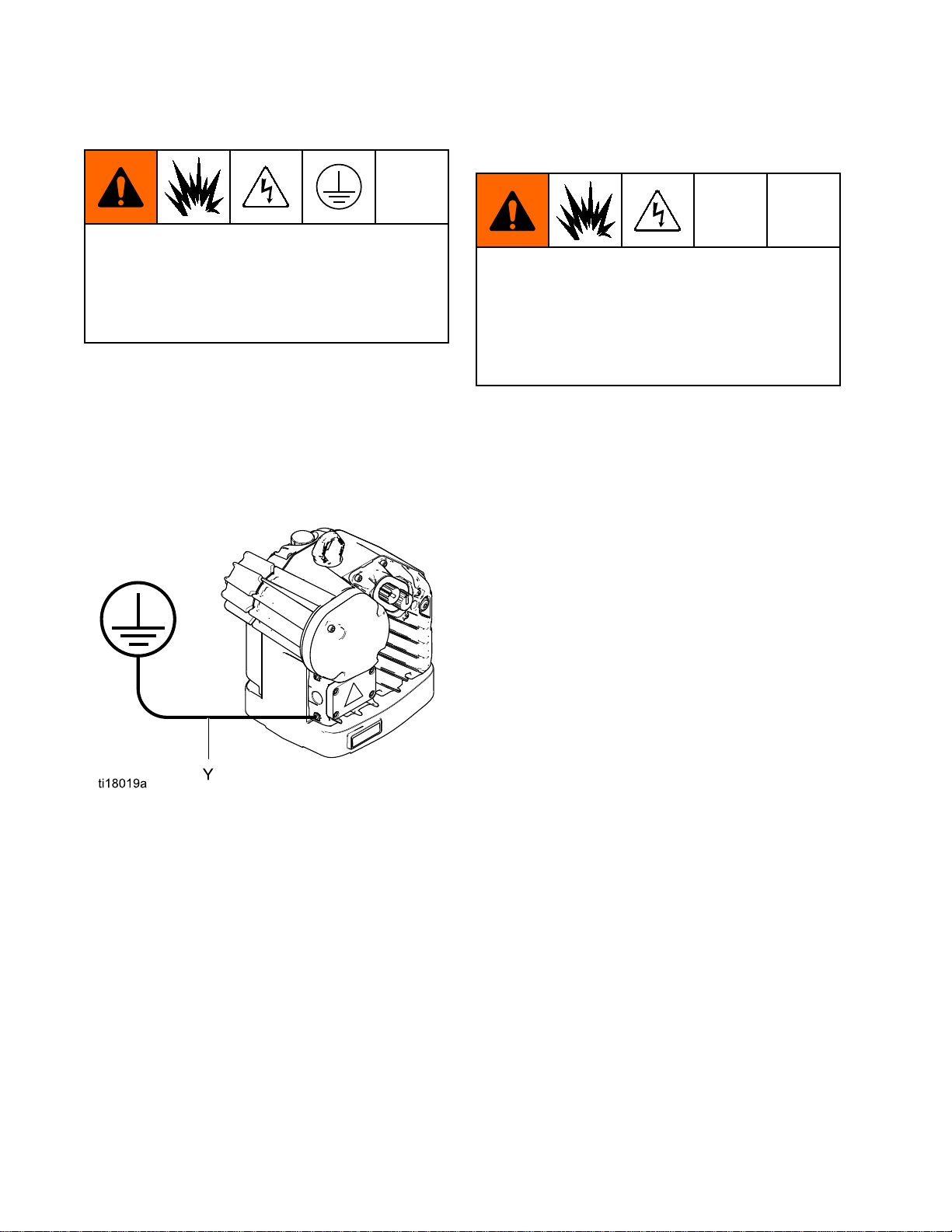
Grounding
Grounding Grounding
Thisequipmentmustbegroundedtoreducethe
riskofstaticsparkingandelectricshock.Electric
orstaticsparkingcancausefumestoigniteor
explode.Impropergroundingcancauseelectric
shock.Groundingprovidesanescapewireforthe
electriccurrent.
NOTE:
NOTE: NOTE:
EM0022,allmotorsmustbebondedtothe
samehighintegrityequipotentialsystem.See
IntrinsicallySafeInstallationRequirementsfor
AdvancedMotors,page12.
Loosenthegroundscrewandattachagroundwire
(Y).Tightenthegroundscrewsecurely.Connectthe
otherendofthegroundwiretoatrueearthground.
ForadvancedmotorsEM0012and
Intrinsically
Intrinsically Intrinsically
Requirements
Requirements Requirements
Donotsubstituteormodifysystemcomponents
asthismayimpairintrinsicsafety.Forinstallation,
maintenance,oroperationinstructions,read
instructionmanuals.Donotinstallequipment
approvedonlyfornon-hazardouslocationina
hazardouslocation.Seetheidenticationlabelfor
theintrinsicsafetyratingforyourmodel.
SeeAppendixA-SystemControlDrawing24N637,
page37,forinstallationrequirementsandentity
parameters.Followallinstallationinstructionsinyour
systemmanual.
Safe
Safe Safe
Installation
Installation Installation
for
Advanced
for for
Advanced Advanced
Motors
Motors Motors
Figure8GroundWire
12
3A2526F
Page 13
Operation
Operation
Operation Operation
Startup
Startup Startup
1.Unlockthefusedsafetyswitch(B)andturniton.
SeeConnectthePowerSupply,page11
2.Pressthestartpushbutton(C).
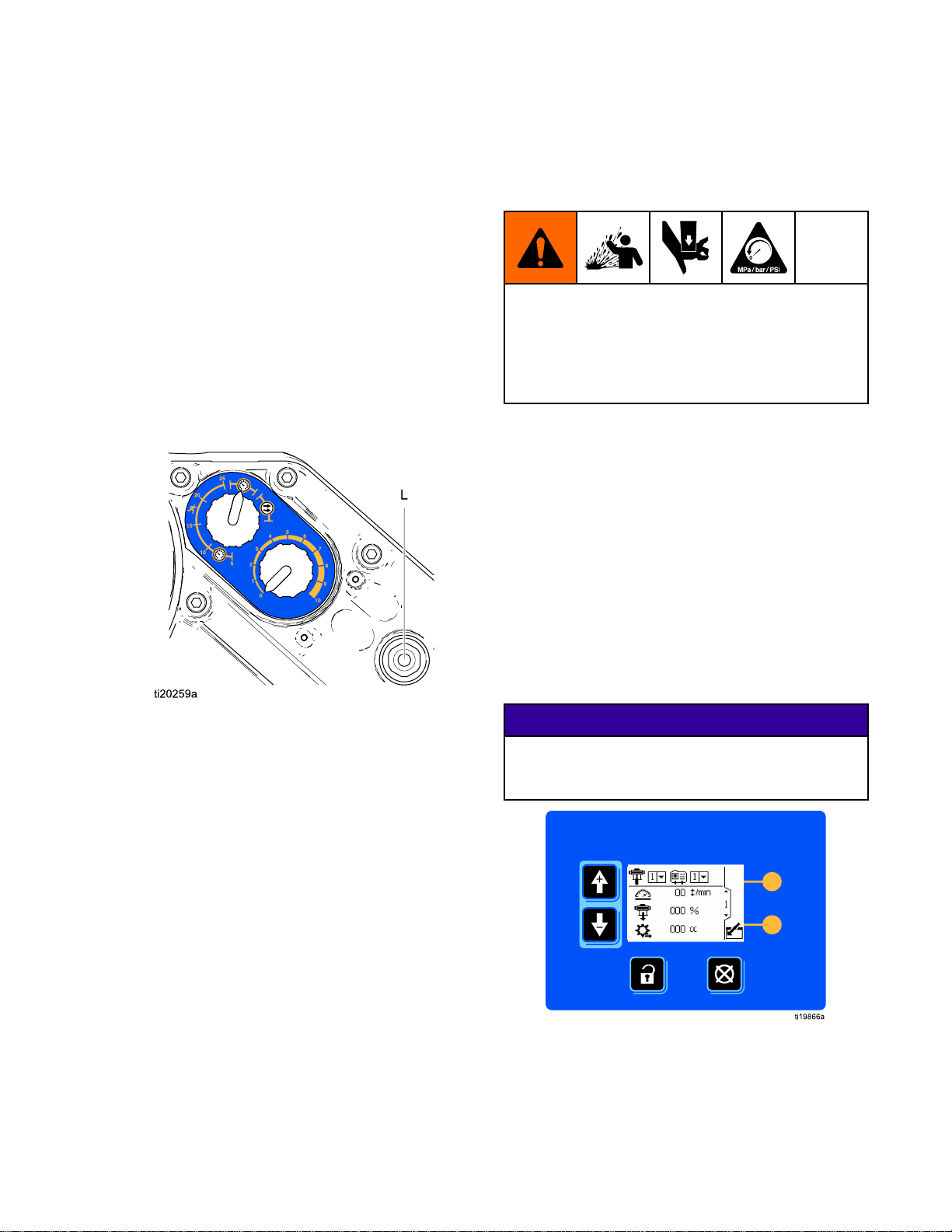
3.Checkthatthepowerindicator(L)islit(steady
on).
4.SeeAdvancedMotorOperation,page13or
BasicMotorOperation,page14forfurther
instructions.
Pressure
Pressure Pressure
Thisequipmentstayspressurizeduntilpressureis
manuallyrelieved.Tohelppreventseriousinjury
fromsplashinguidandmovingparts,followthe
PressureReliefProcedurewhenyoustopspraying
andbeforecleaning,checking,orservicingthe
equipment.
1.Disengagethestart/stopcontrol(C).See
ConnectthePowerSupply,page11
2.Shutoffandlockoutthefusedsafetyswitch(B).
3.Relievealluidpressureasexplainedinyour
separateE-FloDCpumpmanual.
Advanced
Advanced Advanced
TheAdvancedE-FloDCmotorsrequireinstallationof
the24P822ControlModuleAccessoryKittoprovide
theinterfaceforuserstoenterselectionsandview
informationrelatedtosetupandoperation.Seethe
ControlModuleAccessoryKitmanualforinstallation
andoperationinformation.
Relief
Relief Relief
Motor
Motor Motor
Procedure
Procedure Procedure
Operation
Operation Operation
Figure9PowerIndicator
Shutdown
Shutdown Shutdown
FollowthePressureReliefProcedure,page13.
NOTICE
NOTICE NOTICE
Topreventdamagetothesoftkeybuttons,donot
pressthebuttonswithsharpobjectssuchaspens,
plasticcards,orngernails.
Figure10ControlModuleAccessory
3A2526F 13
Page 14
Operation
Basic
Basic Basic
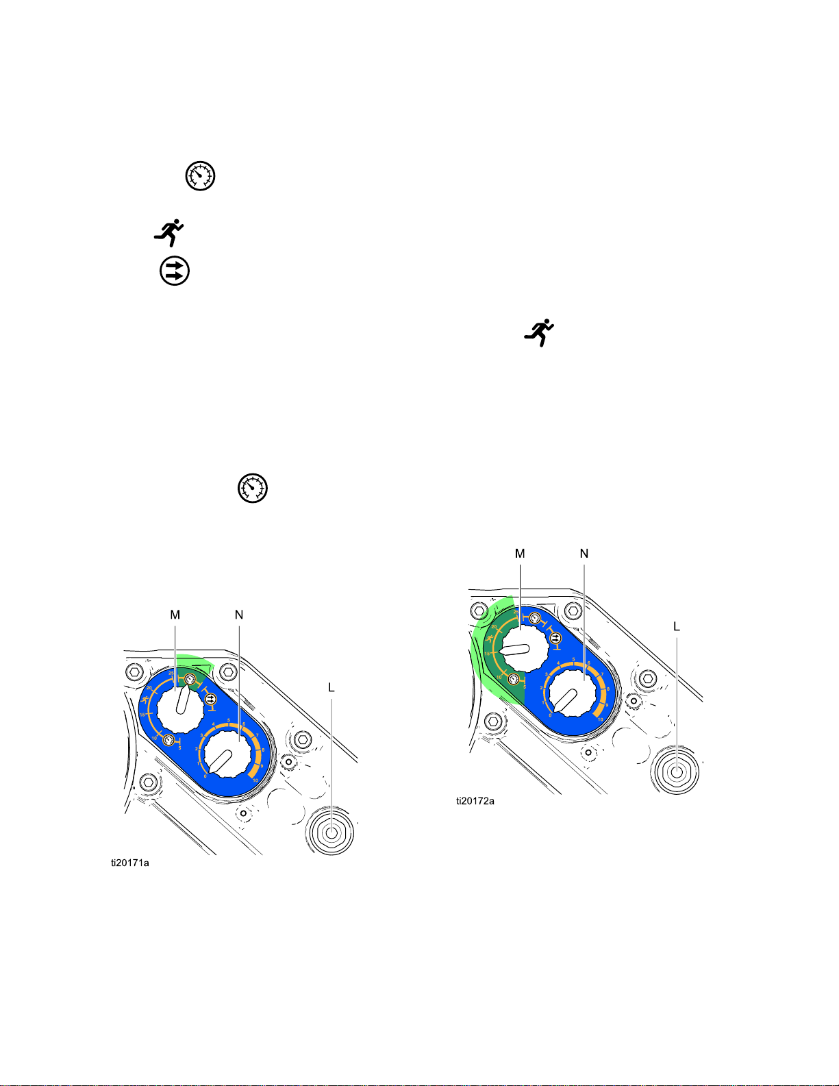
Thebasicmotorhasthreeoperatingmodes:
•PressureMode
•PressureModewithIntegratedRunaway
•FlowMode
NOTE:
NOTE: NOTE:
turntheControlKnob(N)fullycounterclockwiseto0.
Pressure
Pressure Pressure
Wheninpressuremode,themotorwilladjustthe
speedtomaintainaconstantuidpressure.
1.TurntheControlKnob(N)fullycounterclockwise
2.PulltheModeSelectswitch(M)outtoset.Turn
3.PulltheControlKnob(N)outtoset.Turnthe
Motor
Motor Motor
Protection
Beforechangingfromonemodetoanother,
to0.
theswitchtoPressure
tolock.
knobclockwisetoincreasethepressure,or
counterclockwisetodecreasethepressure.
Pushtheknobintolock.
Operation
Operation Operation
Mode
Mode Mode
.Pushtheswitchin
Pressure
Pressure Pressure
Protection
Protection Protection
Inpressuremodewithintegratedrunawayprotection,
themotorwilladjustthespeedtomaintainaconstant
uidpressure,butwillshutdownifitexceedsa
user-setspeed.
1.TurntheControlKnob(N)fullycounterclockwise
to0.
2.PulltheModeSelectswitch(M)outtoset.In
theRunaway
desiredshutdownspeedincyclesperminute(5,
10,15,20,or25).Pushtheswitchintolock.
3.PulltheControlKnob(N)outtoset.Turnthe
knobclockwisetoincreasethepressure,or
counterclockwisetodecreasethepressure.
Pushtheknobintolock.
NOTE:
NOTE: NOTE:
speedisexceededfor5cycles.Toreset,turnthe
ControlKnob(N)fullycounterclockwiseto0,then
turntothedesiredpressure.
Mode
Mode Mode
Themotorwillshutdowniftheselected
with
Integrated
with with
Integrated Integrated
range,turntheswitchtothe
Runaway
Runaway Runaway
Figure11PressureMode
14
Figure12PressureModewithIntegratedRunaway
Protection
3A2526F
Page 15

Flow
Mode
Flow Flow
Mode Mode
Wheninowmode,themotorwillmaintaina
constantspeedregardlessoftheuidpressure,up
tothepump’smaximumworkingpressure.See
TechnicalData,page43.
1.TurntheControlKnob(N)fullycounterclockwise
to0.
2.PulltheModeSelectswitch(M)outtoset.Turn
Operation
theswitchtoFlow
lock.
3.Theamountofowisdeterminedbythecycle
ratesetwiththeControlKnob(N).Theknob’s
scale(0–10)correspondstoacycleadjustment
rangeof0-30cyclesperminute.TurntheControl
Knob(N)clockwisetoincreasethecyclerate
(ow),orcounterclockwisetodecreasethecycle
rate(ow).
.Pushtheswitchinto
Figure13FlowMode
3A2526F 15
Page 16

Maintenance
Maintenance
Maintenance Maintenance
Preventive
Preventive Preventive
Theoperatingconditionsofyourparticularsystem
determinehowoftenmaintenanceisrequired.
Establishapreventivemaintenancescheduleby
recordingwhenandwhatkindofmaintenanceis
needed,andthendeterminearegularschedulefor
checkingyoursystem.
Change
Change Change
NOTE:
NOTE: NOTE:
200,000–300,000cycles.Afterthebreak-inperiod,
changetheoilonceayear.OrdertwoPartNo.
16W645ISO220silicone-freesyntheticgearoil.
1.Placeaminimum2quart(1.9liter)container
2.Reinstalltheoildrainplug(25).Torqueto25–30
3.Openthellcap(P)andaddGracoPartNo.
Changetheoilafterabreak-inperiodof
undertheoildrainport.Removetheoildrain
plug(25).Allowalloiltodrainfromthemotor.
ft-lb(34–40N•m).
16W645ISO220silicone-freesyntheticgear
oil.Checktheoillevelinthesightglass(K).Fill
untiltheoillevelisnearthehalfwaypointofthe
sightglass.Theoilcapacityisapproximately1.5
quarts(1.4liters).Do Do
Maintenance
Maintenance Maintenance
the
Oil
the the
Oil Oil
Do
not
not not
Schedule
Schedule Schedule
overll.
overll. overll.
Check
Check Check
Checktheoillevelinthesightglass(K).Theoil
levelshouldbenearthehalfwaypointofthesight
glasswhentheunitisnotrunning.Iflow,openthe
llcap(P)andaddGracoPartNo.16W645ISO220
silicone-freesyntheticgearoilasrequired.Theoil
capacityisapproximately1.5quarts(1.4liters).Do Do
not
not not
Figure15SightglassandOilFillCap
Oil
Level
Oil Oil
Level Level
overll.
overll. overll.
Do
4.Reinstallthellcap.
Figure14OilDrainPlug
Bearing
Bearing Bearing
Thebearingpre-loads(R)arefactorysetandarenot
useradjustable.Donotadjustthebearingpre-loads.
Pre
Load
Pre Pre
- --Load Load
16 3A2526F
Page 17

ErrorCodeTroubleshooting
Error
Error Error
Errorcodescantakethreeforms:
•Alarm:alertsyoutothealarmcauseandshuts
downthepump.
•Deviation:alertsyoutotheproblem,butpump
maycontinuetorunpastthesetlimitsuntilthe
system’sabsolutelimitsarereached.
•Advisory:informationonly.Pumpwillcontinueto
operate.
NOTE:
NOTE: NOTE:
pressure(Pcodes)canbedesignatedasalarms
ordeviations.SeeSetup Setup
ModuleManual.
Applicable
Applicable Applicable
Advanced1–2
AdvancedNone
Code
Code Code
OnAdvancedmotors,ow(Kcodes)and
Motor
Motor Motor
Troubleshooting
Troubleshooting Troubleshooting
Setup
Screen
Screen Screen
Blink
Code
Blink Blink
Code Code
4 44intheControl
Display
Display Display
Code
Code Code
K1D?
K2D?
NOTE:
NOTE: NOTE:
thecodeisassociatedwiththedisplayonly.
NOTE:
NOTE: NOTE:
codeisaplaceholderfortheunitnumberwherethe
eventoccurred.
NOTE:
NOTE: NOTE:
indicatoronthemotor.Theblinkcodegivenbelow
indicatesthesequence.Forexample,blinkcode1–2
indicates1blink,then2blinks;thesequencethen
repeats.
NOTE:
NOTE: NOTE:
anindicatorofwhichpumpisactive(
hasbeenpushed,seeRun Run
ModuleManual).
Alarm
Alarm Alarm
Deviation
Deviation Deviation
AlarmFlowisbelowminimumlimit.
DeviationFlowisbelowminimumlimit.
Intheerrorcodeslistedbelow,an“X”means
Intheerrorcodeslistedbelow,a“?”inthe
Theblinkcodeisdisplayedusingthepower
Ablinkcodeof9isnotanerrorcode,but
Run
Screen
Screen Screen
or
or or
Description
Description Description
softkey
1 11intheControl
Basicand
Advanced
AdvancedNone
Advanced1–3
AdvancedNone
Advanced1–4
AdvancedNone
Basicand
Advanced
Basicand
Advanced
Advanced2–3
AdvancedNone
1
2
3
K4D?
K3D?
P1I?
P2I?
P4I?
P3I?
V1I?
V4I?
CAD?
CAC?
AlarmFlowexceedsmaximumtarget;also
indicatespumprunawayconditionexists.
DeviationFlowexceedsmaximumtarget;also
indicatespumprunawayconditionexists.
AlarmPressureisbelowminimumlimit.
DeviationPressureisbelowminimumlimit.
AlarmPressureexceedsmaximumtarget.
DeviationPressureexceedsmaximumtarget.
AlarmBrownout;voltagesuppliedtomotoristoo
low.
AlarmVoltagesuppliedtomotoristoohigh.
Alarm
Alarm
UnitdetectsalossofCANcommunication.
Thisalarmisonlylogged.Noashing
alarmappearsonthedisplay,buttheblink
codedoesoccur.
DisplaydetectsalossofCAN
communication.Flashingalarm
appearsonthedisplay,andtheblinkcode
occurs.
CONTINUED ON THE NEXT PAGE.
3A2526F
17
Page 18

ErrorCodeTroubleshooting
Applicable
Applicable Applicable
Motor
Motor Motor
Advanced2–4
Basicand
Advanced
Advanced1–5
Basicand
Advanced
AdvancedNoneP5DXDeviationMorethanonepumpisassignedtoa
AdvancedNone
Advanced1–6
AdvancedNone
Blink
Code
Blink Blink
Code Code
4
5
Display
Display Display
CAG?
WXD?
WSD?
T3D?
P6CAor
P6CB
P6D?
MND?
Code
Code Code
Alarm
Alarm Alarm
Deviation
Deviation Deviation
Deviation
DeviationForunitswithoutclosedlooppressure
AdvisoryMaintenancecounterisenabledand
or
or or
Alarm
Alarm
Alarm
AlarmForunitswithclosedlooppressurecontrol:
Displaydetectsalossofmodbus
communicationwhencontrolaccessisset
tomodbus.
Aninternalcontrolboardhardwarefailure
isdetected.
Invalidlowersize;occursiftheunitis
operatedbeforesettingupthelowersize.
Overtemperature.
transducer.Theassignmentforthat
transducerisautomaticallyclearedunder
thiscondition.Usermustreassign.
control:Transducer(AorB)isenabled
butnotdetected.
Transducerisenabledbutnotdetected.
countdownreachedzero(0).
Description
Description Description
Basic6NoneAlarm
Basicand
Advanced
Basicand
Advanced
Basicand
Advanced
Basicand
Advanced
Basicand
Advanced
Basicand
Advanced
2–6
3–5
3–4
3–6
4–5
9NoneNone
V1M?
T2D?
WNC?
CCN?
WMC?
TheModeSelectknobissetbetween
PressureandFlow.Setknob
tothedesiredmode.
Alarm
AlarmInternalthermistordisconnected.
Alarm
Alarm
Alarm
ACpowerislost.
Softwareversionsdonotmatch.
Circuitboardcommunicationfailure.
Internalsoftwareerror.
Ablinkcodeof9isnotanerrorcode,but
anindicatorofwhichpumpisactive(see
NOTE
NOTE NOTE
above).
18 3A2526F
Page 19

Repair
Repair
Repair Repair
Replace
Replace Replace
1.Stopthepumpatthebottomofitsstroke.Shut
offandlockoutpowertothemotor.
2.FollowthePressureReliefProcedure,page13.
3.Disconnectthelowerfromthemotor,as
explainedinyourseparateE-FloDCpump
manual.
Output
Output Output
Seal
Seal Seal
Cartridge
Cartridge Cartridge
4.Draintheoilfromthemotor.See
ChangetheOil,page16.
5.Reinstalltheoildrainplug.Torqueto25–30ft-lb
(34–40N•m).
6.Unscrewtheoutputcartridge(19)fromthemotor.
SeeParts,page20.
7.Installthenewoutputcartridge.Torqueto70–80
ft-lb(95–108N•m).
8.Fillwithoil.SeeChangetheOil,page16.
9.Reconnectthelowertothemotor.
10.Turnonpowerandresumeoperation.
3A2526F 19
Page 20

Parts
Parts
Parts Parts
Basic
Basic Basic
EM0011,
EM0011, EM0011,
EM0013,
EM0013, EM0013,
EM0021,
EM0021, EM0021,
EM0023,
EM0023, EM0023,
Motor
Motor Motor
Series
Series Series
Series
Series Series
Series
Series Series
Series
Series Series
Assembly
Assembly Assembly
A,
Horsepower
A, A,
1 11Horsepower Horsepower
A,
Horsepower
A, A,
1 11Horsepower Horsepower
A,
Horsepower
A, A,
2 22Horsepower Horsepower
A,
Horsepower
A, A,
2 22Horsepower Horsepower
Motor
Motor Motor
Motor,
Motor, Motor,
Motor
Motor Motor
Motor,
Motor, Motor,
with
Region-Specic
with with
Region-Specic Region-Specic
with
Region-Specic
with with
Region-Specic Region-Specic
Approvals
Approvals Approvals
Approvals
Approvals Approvals
20 3A2526F
Page 21

Parts
EM0011,
EM0011, EM0011,
EM0013,
EM0013, EM0013,
EM0021,
EM0021, EM0021,
EM0023,
EM0023, EM0023,
Ref
Ref Ref
1
3116343
915F931
1315H525
1424E315
1924K341
24
2515H432
27
33▲16M130LABEL,warning
Part
Part Part
———
———
———
Series
Series Series
Series
Series Series
Series
Series Series
Series
Series Series
A,
A, A,
1 11Horsepower Horsepower
A,
A, A,
1 11Horsepower Horsepower
A,
A, A,
2 22Horsepower Horsepower
A,
A, A,
2 22Horsepower Horsepower
Horsepower
Horsepower
Horsepower
Horsepower
Description
Description Description
HOUSING,motor
SCREW,ground;M5
x0.8
RING,lift
CAP,oilll
SIGHTGLASS
CARTRIDGE,output
seal
SCREW,cap,socket
head;M8x1.25;30
mm
PLUG,oildrain
COVER,electrical
compartment
(EM0011and
EM0021)
Motor
Motor Motor
Motor,
Motor, Motor,
Motor
Motor Motor
Motor,
Motor, Motor,
with
Region-Specic
with with
Region-Specic Region-Specic
with
Region-Specic
with with
Region-Specic Region-Specic
Qty
Qty Qty
1
3
1
1
1
1
4
1
1
1
Approvals
Approvals Approvals
Approvals
Approvals Approvals
Part
Ref
Part Part
Ref Ref
16W360LABEL,warning
34▲196548LABEL,warning1
3616U113KIT,knob;kit
3816W645
———
43
Description
Description Description
(EM0013and
EM0023)
includesreplacement
partsforoneknob
OIL,gear,synthetic;
ISO220silicone-free;
1quart(0.95liter);
notshown
WASHER,lock,
spring;no.8
Qty
Qty Qty
1
2
2
4
▲ReplacementDangerandWarninglabels,tags,
andcardsareavailableatnocost.
Itemsmarked———arenotavailableseparately.
3A2526F
21
Page 22

Parts
Advanced
Advanced Advanced
EM0012,
EM0012, EM0012,
EM0014,
EM0014, EM0014,
EM0022,
EM0022, EM0022,
EM0024,
EM0024, EM0024,
EM0025,
EM0025, EM0025,
EM0026,
EM0026, EM0026,
Motor
Motor Motor
Series
Series Series
Series
Series Series
Series
Series Series
Series
Series Series
Series
Series Series
Series
Series Series
A,
A, A,
A,
A, A,
A,
A, A,
A,
A, A,
A,
A, A,
A,
A, A,
Assembly
Assembly Assembly
Horsepower
1 11Horsepower Horsepower
Horsepower
1 11Horsepower Horsepower
Horsepower
2 22Horsepower Horsepower
Horsepower
2 22Horsepower Horsepower
Horsepower
2 22Horsepower Horsepower
Horsepower
2 22Horsepower Horsepower
Motor
Motor Motor
Motor,
Motor, Motor,
Motor
Motor Motor
Motor,
Motor, Motor,
Motor
Motor Motor
Motor,
Motor, Motor,
with
Region-Specic
with with
Region-Specic Region-Specic
with
Region-Specic
with with
Region-Specic Region-Specic
with
Region-Specic
with with
Region-Specic Region-Specic
Approvals
Approvals Approvals
Approvals
Approvals Approvals
Approvals
Approvals Approvals
22
3A2526F
Page 23

Parts
EM0012,
EM0012, EM0012,
EM0014,
EM0014, EM0014,
EM0022,
EM0022, EM0022,
EM0024,
EM0024, EM0024,
EM0025,
EM0025, EM0025,
EM0026,
EM0026, EM0026,
Ref
Ref Ref
1
3116343
915F931
1315H525
1424E315
1924K341
24
2515H432
27
Part
Part Part
———
———
———
Series
Series Series
Series
Series Series
Series
Series Series
Series
Series Series
Series
Series Series
Series
Series Series
A,
Horsepower
A, A,
1 11Horsepower Horsepower
A,
Horsepower
A, A,
1 11Horsepower Horsepower
A,
Horsepower
A, A,
2 22Horsepower Horsepower
A,
Horsepower
A, A,
2 22Horsepower Horsepower
A,
Horsepower
A, A,
2 22Horsepower Horsepower
A,
Horsepower
A, A,
2 22Horsepower Horsepower
Description
Description Description
HOUSING,motor
SCREW,ground;M5
x0.8
RING,lift
CAP,oilll
SIGHTGLASS
CARTRIDGE,output
seal
SCREW,cap,socket
head;M8x1.25;30
mm
PLUG,oildrain
COVER,electrical
compartment
Motor
Motor Motor
Motor,
Motor, Motor,
Motor
Motor Motor
Motor,
Motor, Motor,
Motor
Motor Motor
Motor,
Motor, Motor,
with
Region-Specic
with with
Region-Specic Region-Specic
with
Region-Specic
with with
Region-Specic Region-Specic
with
Region-Specic
with with
Region-Specic Region-Specic
Qty
Qty Qty
1
3
1
1
1
1
4
1
1
Approvals
Approvals Approvals
Approvals
Approvals Approvals
Approvals
Approvals Approvals
Part
Ref
Part Part
Ref Ref
33▲16M130LABEL,warning
16W360LABEL,warning
34▲196548LABEL,warning1
3816W645
———
43
Description
Description Description
(EM0012,EM0022,
andEM0025)
(EM0014,EM0024,
andEM0026)
OIL,gear,synthetic;
ISO220silicone-free;
1quart(0.95liter);
notshown
WASHER,lock,
spring;no.8
Qty
Qty Qty
1
1
2
4
▲ReplacementDangerandWarninglabels,tags,
andcardsareavailableatnocost.
Itemsmarked———arenotavailableseparately.
3A2526F 23
Page 24

Notes
Notes
Notes Notes
24
3A2526F
Page 25

RepairKits,RelatedManuals,andAccessories
Repair
Repair Repair
Motor
Motor Motor
Allmotorsinthis
manual.
ModelsEM00X1,
EM00X3
Kits,
Kits, Kits,
Part
No.
Part Part
No. No.
Related
Related Related
Description
Description Description
E-FloDCMotors
E-FloDCBasicMotors
Manuals,
Manuals, Manuals,
Kits
Kits Kits
24K341
24P816
255143WallBracket;seemanual312148.
16W645
16U705
24U938Encoder;seeEncoderReplacement,page29
108675WiringPost
16U113
24U934
24U936
and
and and
Accessories
Accessories Accessories
Kit
Description
Kit Kit
Description Description
OutputSealCartridge(19);see
Parts,page20.
ShaftCollectorKit;seemanual406998.
ISO220Silicone-FreeSyntheticGearOil;
1quart(0.95liter);order2
PositionSensor;see
PositionSensorReplacement,page32.
KnobKit(36);seeParts,page20.Includes
replacementpartsforoneknob.
Electric1HPControlBoard;see
ControlBoardReplacement,page27
Electric2HPControlBoard;see
ControlBoardReplacement,page27
ModelsEM0012,
EM0014,
EM0022,
EM0024,
EM0025,and
EM0026
E-FloDCAdvancedMotors
24P822
16P911
16P912
24P979
24R050PressureTransducerKit
16U729
24U935
24U937
24U939Powerboard
ControlModule,forAdvancedMotors;see
manual3A2527.
CANCable,3ft(1m)
CANCable,25ft(8m)
PneumaticControlforBackPressure
Regulator;seemanual332142.
Start/StopSwitch.Allowspumptobeshut
offwhilemaintainingpowertothecontrol
module.
Electric1HPControlBoardsee
ControlBoardReplacement,page27
Electric2HPControlBoard
seeControlBoardReplacement,page27
3A2526F 25
Page 26

RepairKits,RelatedManuals,andAccessories
Motor
Part
Motor Motor
No.
Part Part
No. No.
Description
Description Description
Kits
Kits Kits
Kit
Description
Kit Kit
Description Description
Allmotorsinthis
manual.
Connectionkits,tomountan
E-FloDCMotortoanexisting
pumplower.Kitsincludetie
rods,tierodnuts,adapter,
andcoupler.
288203For3000and4000cc4–BallLowers
288204ForDura-Flo1800and2400Lowers
288205ForDura-Flo600,750,900,and1200
Lowers
288206ForDura-Flo1000Lowers
288207ForXtreme145,180,220,250,and290
Lowers
288209For750,1000,1500,and2000cc4–Ball
Lowers
288860ForXtreme85and115Lowers
26 3A2526F
Page 27

ControlBoardReplacement
Kits 24U934, 24U936, 24U935, 24U937
Control
Control Control
Kits
Kits Kits
Overview
Overview Overview
Themaincontrolboardassemblymanagesthe
operationoftheE-FloDC.Itispermanentlyattached
totheelectronicscover.
Tools
Tools Tools
•6mmHexWrench
•PhillipsScrewdriver(#1)
•TorqueWrench(15ft-lb,20Nm)
Replacement
Replacement Replacement
Toavoidelectricshock,turnoffequipmentpower
andshutoffpoweratmaincircuitbreakerbefore
installing.
Toavoiddamagetothecontrolboardwear
groundingstrap(PartNo.112190)andground
appropriately.
Prepare
Prepare Prepare
1.Removepowerfromthemotor.Follow
24U934,
24U934, 24U934,
Required
Required Required
appropriatelock-out/tag-outprocedures.
Board
Board Board
Instructions
Instructions Instructions
NOTICE
NOTICE NOTICE
Motor
Motor Motor
Replacement
Replacement Replacement
24U936,
24U936, 24U936,
24U935,
24U935, 24U935,
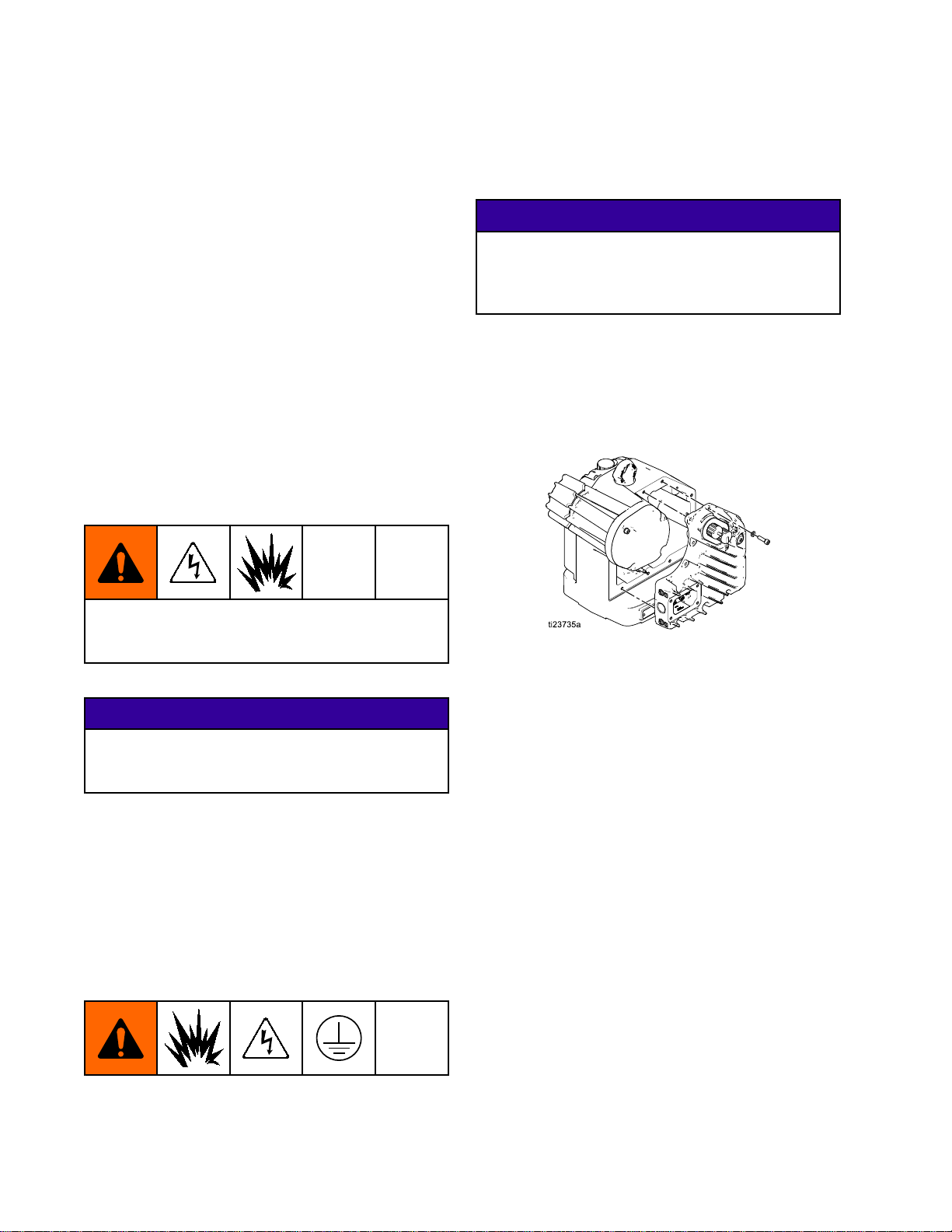
Figure16WiringBoxCover
Remove
Remove Remove
1.Removethe12boltsthatholdontheelectronics
2.Supportthecoveraftertheboltsareremovedto
24U937
24U937 24U937
Electronics
Electronics Electronics
Toavoidequipmentdamage,carefullysupportthe
coverwhenremovingthelastbolt.Holdthecover
horizontallyandtakecarethatthewiresarenot
pulledtight.
coverusinga6mmhexwrench.Placeboltsina
safelocation.
preventputtingexcessstrainonthewiresinside
theE-FloDC.
Cover
Cover Cover
NOTICE
NOTICE NOTICE
2.FollowthePressureReliefProcedure,page13.
3.Decouplethepumplowerfromthemotorperthe
appropriatepumpmanual.
Disconnect
Disconnect Disconnect
1.SeeRemovethe4boltsthatholdonthewiring
boxcoverusinga6mmhexwrench.Placebolts
inasafelocation.
2.Disconnectwiresfrompostandgroundscrew
insideofcover.
3.Removepowercableand/orconduitfrom
electronicscover.
3A2526F
Power
Power Power
Wires
Wires Wires
Figure17ElectronicsCover
Disconnect
Disconnect Disconnect
NOTE:
NOTE: NOTE:
cover.Toreplacethecontrolboardtheentire
electronicscovermustbereplaced.
Control
Control Control
Thecontrolboardisinsidetheelectronics
Board
Board Board
27
Page 28

ControlBoardReplacement
Kits 24U934, 24U936, 24U935, 24U937
1.Todisconnectthecontrolboardunplugthe
positionsensor,encoder,temperaturesensor,
andmotorfromthecontrolboard.
2.Removewiresfromclipinsidehousing.
3.Removeanytiestrapsthatmaybepresent.
4.Settheelectronicscover/controlboardaside.
Foradvancedmodelssee
DisconnectPowerBarrierBoard,page35.
Install
Install Install
1.Plugthepositionsensor,encoder,temperature
2.Secureloosewiresintotheclipinsidethe
Foradvancedmodelssee
InstallNewPowerBarrierBoard,page35.
Reset
Reset Reset
Tocalibratetheunitadipswitchonthecontrolboard
mustbetoggled.Therearetwodipswitcheslocated
ontheuppercontrolboard.Reseteitherdipswitch
bytogglingittotheoppositestate.Thissignals
thecontrolboardthatareplacementparthasbeen
installed.Thenexttimetheunitispowereditwill
proceedwithanauto-calibrationsequence.
NOTE:
NOTE: NOTE:
procedurethedipswitchonlyneedstobetoggled
intotheoppositestateonetime.
New
Control
New New
Control Control
sensor,andmotorintothenewcontrolboard.
housing.
Dip
Switch
Dip Dip
Switch Switch
Ifyouareperformingmorethanonerepair
Board
Board Board
Reinstall
Reinstall Reinstall
Besurethatnowiresarepinchedbetweenthe
electronicscoverandthemotorhousing.Pinched
wiresmaydamagethecontrolboardandwillimpair
explosion-proofsafety.
1.Reinstallelectronicscoverontocenterhousing.
2.Installthe12boltsusinga6mmhexwrench.
NOTE:
NOTE: NOTE:
3.Torquetheboltsto15ft-lb(20Nm).
Reinstall
Reinstall Reinstall
1.Connectwiresfrominsideofwiringbox.Referto
torqueinstructionslistedonplacardinsideofthe
wiringbox.Connectpowercableand/orconduit
totheelectronicscover.
2.Reinstallcoverontowiringbox.
3.Installthe4boltsusinga6mmhexwrench.
NOTE:
NOTE: NOTE:
4.Torquetheboltsto15ft-lb(20Nm).
Power
Power Power
1.Applypowertotheunittostarttheauto-calibration
process.
Electronics
Electronics Electronics
Ensurethelockwashersarestillinplace.
Wiring
Wiring Wiring
Ensurethelockwashersarestillinplace.
Unit
Unit Unit
Cover
Cover Cover
Box
Cover
Box Box
Cover Cover
2.Themotoroutputshaftwillrunupanddownover
thecourseofseveralminutes.
3.Midwaythroughtheauto-calibrationprocessthe
motoroutputshaftwillpauseasitmovestothe
nextstep.
4.Ensuretheauto-calibrationprocessiscomplete
beforecontinuing.
Reattach
Reattach Reattach
Figure18DipSwitch
28 3A2526F
1.Jogtheoutputshaftonthepumplowerand
reconnectthecouplingnut.
2.Torquetotheproperlevelpertheappropriate
pumpmanual.
Pump
Pump Pump
Lower
Lower Lower
Page 29

EncoderReplacement
Kit 24U938
Encoder
Encoder Encoder
Kit
Kit Kit
Overview
Overview Overview
TheencoderisusedbytheE-FloDCfortwo
purposes.First,theencodertellsthecontrolboard
wherethemotorisinitsmechanicalrotationand
usesthatinformationtoproperlycontrolthemotor
torque.Second,itcontrolsstrokelengthbyallowing
thecontrolboardtocountthenumberofcomplete
motorrotations.
Tools
Tools Tools
•6mmHexWrench
•.050inHexWrench
•PhillipsScrewdriver(#1)
•TorqueWrench(15ft-lb,20Nm)
•Blue(medium)threadlockingcompound
Replacement
Replacement Replacement
24U938
24U938 24U938
Required
Required Required
Replacement
Replacement Replacement
Instructions
Instructions Instructions
2.FollowthePressureReliefProcedure,page13.
3.Decouplethepumplowerfromthemotorperthe
appropriatepumpmanual.
Remove
Remove Remove
Toavoidequipmentdamage,carefullysupportthe
coverwhenremovingthelastbolt.Holdthecover
horizontallyandtakecarethatthewiresarenot
pulledtight.
1.Removethe12boltsthatholdontheelectronics
coverusinga6mmhexwrench.Placeboltsina
safelocation.
Electronics
Electronics Electronics
Cover
Cover Cover
NOTICE
NOTICE NOTICE
Toavoidelectricshock,turnoffequipmentpower
andshutoffpoweratmaincircuitbreakerbefore
installing.
NOTICE
NOTICE NOTICE
Toavoiddamagetothecontrolboardwear
groundingstrap(PartNo.112190)andground
appropriately.
Prepare
Prepare Prepare
1.Removepowerfromthemotor.Follow
Motor
Motor Motor
appropriatelock-out/tag-outprocedures.
2.Supportthecoveraftertheboltsareremovedto
preventputtingexcessstrainonthewiresinside
theE-FloDC.
Figure19ElectronicsCover
3A2526F 29
Page 30

EncoderReplacement
Kit 24U938
Remove
Remove Remove
1.Removethe4boltsthatholdonthemotorcover
usinga6mmhexwrench.Placeboltsinasafe
location.
2.Setmotorcoveraside.
Figure20MotorCover
Remove
Remove Remove
Motor
Motor Motor
Encoder
Encoder Encoder
Cover
Cover Cover
AA
Setscrews
AB
Encodermountingange
Phillipsheadmountingscrews
AC
ADMotorhousing
Install
Install Install
1.Placetheencoderconnectorcable(AE)through
New
Encoder
New New
Encoder Encoder
themotorhousinglowerport(AF).
NOTE:
NOTE: NOTE:
thetwoconnections.
Theencoderconnectoristhesmallerof
1.Unplugtheencodercablefromthecontrolboard
andtheencoderandremove.
2.Loosenthe2hubsetscrews(AA)usingthe
included.050”hexwrench.
3.Removethe2mountingscrews(AC)witha
Phillipsheadscrewdriver.
4.Pullencoderoffofrotorshaft.
NOTE:
NOTE: NOTE:
the2Phillipsheadmountingscrews.Allotherbolts
shouldremaininplace.
Thisprocedureonlyrequirestheremovalof
Figure22EncoderCable
AEEncoderconnectorcable
AF
Lowerportofmotorhousing
2.Slidethenewencoderontotherotorshaft.
3.Applyasmallamountofblue(medium)thread
lockertothe2Phillipsheadmountingscrews
(AC)andsecureencodermountingange(AB)
tomotorhousing(AD).
4.Removethe2setscrews(AA)fromtheencoder
hubusingtheincluded.050”hexwrench.
5.Applyasmallamountofblue(medium)thread
lockertothesetscrews(AA)andscrewbackinto
theencoder.Tightenhandtight.
6.Plugencodercableintotheencoderandthe
controlboard.
Figure21Encoder
30 3A2526F
Page 31

EncoderReplacement
Kit 24U938
Figure23Encoder
AA
Setscrews
AB
Encodermountingange
Phillipsheadmountingscrews
AC
ADMotorhousing
Reset
Reset Reset
Tocalibratetheunitadipswitchonthecontrolboard
mustbetoggled.Therearetwodipswitcheslocated
ontheuppercontrolboard.Reseteitherdipswitch
bytogglingittotheoppositestate.Thissignals
thecontrolboardthatareplacementparthasbeen
installed.Thenexttimetheunitispowereditwill
proceedwithanauto-calibrationsequence.
NOTE:
NOTE: NOTE:
procedurethedipswitchonlyneedstobetoggled
intotheoppositestateonetime.
Dip
Switch
Dip Dip
Switch Switch
Ifyouareperformingmorethanonerepair
Reinstall
Reinstall Reinstall
Besurethatnowiresarepinchedbetweenthe
electronicscoverandthemotorhousing.Pinched
wiresmaydamagethecontrolboardandwillimpair
explosion-proofsafety.
1.Reinstallelectronicscoverontocenterhousing.
2.Installthe12boltsusinga6mmhexwrench.
NOTE:
NOTE: NOTE:
3.Torquetheboltsto15ft-lb(20Nm).
Reinstall
Reinstall Reinstall
1.Reinstallmotorcoverontomotorhousing.
2.Installthe4boltsthatholdonthemotorcover
usinga6mmhexwrench.Ensurethelock
washersarestillinplace.
3.Torquetheboltsto15ft-lb(20Nm).
Power
Power Power
1.Applypowertotheunittostarttheauto-calibration
process.
2.Themotoroutputshaftwillrunupanddownover
thecourseofseveralminutes.
3.Midwaythroughtheauto-calibrationprocessthe
motoroutputshaftwillpauseasitmovestothe
nextstep.
4.Ensuretheauto-calibrationprocessiscomplete
beforecontinuing.
Electronics
Electronics Electronics
Ensurethelockwashersarestillinplace.
Motor
Motor Motor
Unit
Unit Unit
Cover
Cover Cover
Cover
Cover Cover
Reattach
Reattach Reattach
1.Jogtheoutputshaftonthepumplowerand
reconnectthecouplingnut.
2.Torquetotheproperlevelpertheappropriate
Figure24DipSwitch
3A2526F 31
pumpmanual.
Pump
Pump Pump
Lower
Lower Lower
Page 32
PositionSensorReplacement
Kit 16U705
Position
Position Position
Kit
Kit Kit
Overview
Overview Overview
ThepositionsensorisusedbytheE-FloDCto
determinewherethemotorisinthestroke.
Tools
Tools Tools
•6mmHexWrenches
•13mmOpen-EndedWrench
•6mmOpen-EndedWrench
•PhillipsScrewdriver(#2)
•TorqueWrench(15ft-lb,20Nm)
Replacement
Replacement Replacement
16U705
16U705 16U705
Required
Required Required
Sensor
Sensor Sensor
Instructions
Instructions Instructions
Replacement
Replacement Replacement
NOTICE
NOTICE NOTICE
Toavoidequipmentdamage,carefullysupportthe
coverwhenremovingthelastbolt.Holdthecover
horizontallyandtakecarethatthewiresarenot
pulledtight.
1.Removethe12boltsthatholdontheelectronics
coverusinga6mmhexwrench.Placeboltsina
safelocation.
2.Supportthecoveraftertheboltsareremovedto
preventputtingexcessstrainonthewiresinside
theE-FloDC.
Toavoidelectricshock,turnoffequipmentpower
andshutoffpoweratmaincircuitbreakerbefore
installing.
NOTICE
NOTICE NOTICE
Toavoiddamagetothecontrolboardwear
groundingstrap(PartNo.112190)andground
appropriately.
Prepare
Prepare Prepare
1.Removepowerfromthemotor.Follow
2.FollowthePressureReliefProcedure,page13.
3.Decouplethepumplowerfromthemotorperthe
Remove
Remove Remove
Motor
Motor Motor
appropriatelock-out/tag-outprocedures.
appropriatepumpmanual.
Electronics
Electronics Electronics
Cover
Cover Cover
Figure25ElectronicsCover
Remove
Remove Remove
1.Unplugthepositionsensorfromthecontrol
board.
2.Unscrewtheshieldground(AT)usingaPhillips
screwdriver.
3.Loosenthepositionsensorjamnut(AS)using
a13mmwrench.
4.Unscrewthepositionsensor(AR)fromthecenter
housingusinga6mmopenendedwrench.
NOTE:
NOTE: NOTE:
topreventtwisting.
Install
Install Install
1.Carefullyscrewthereplacementpositionsensor
intothecenterhousing.
NOTE:
NOTE: NOTE:
wireswillhavetoberotatedwhiletheposition
sensorisinstalledtopreventthemfrombeing
twisted.
Position
Position Position
Allowwirestorotatewithpositionsensor
New
Position
New New
Position Position
Becarefulnottodamagethewires.The
Sensor
Sensor Sensor
Sensor
Sensor Sensor
32 3A2526F
Page 33

PositionSensorReplacement
Kit 16U705
2.Usethe6mmwrenchtocompletetheinstallation
ofthepositionsensor.Becarefulnottouse
excessivetorque.Stoponcethepositionsensor
bottomsoutinthebore.
NOTE:
NOTE: NOTE:
Damagetothepositionsensormayresult.
3.Tightenthejamnutonthepositionsensornger
tight.
NOTE:
NOTE: NOTE:
nut.Damagetothepositionsensormayresult.
4.InstallshieldgroundwireusingaPhillipsscrew
driver.
5.Plugthepositionsensorintothecontrolboard.
Reset
Reset Reset
Tocalibratetheunitadipswitchonthecontrolboard
mustbetoggled.Therearetwodipswitcheslocated
ontheuppercontrolboard.Reseteitherdipswitch
bytogglingittotheoppositestate.Thissignals
thecontrolboardthatareplacementparthasbeen
installed.Thenexttimetheunitispowereditwill
proceedwithanauto-calibrationsequence.
NOTE:
NOTE: NOTE:
procedurethedipswitchonlyneedstobetoggled
intotheoppositestateonetime.
Donotovertightenthepositionsensor.
DoNOTuseawrenchtotightenthejam
Dip
Switch
Dip Dip
Switch Switch
Ifyouareperformingmorethanonerepair
Reinstall
Reinstall Reinstall
Besurethatnowiresarepinchedbetweenthe
electronicscoverandthemotorhousing.Pinched
wiresmaydamagethecontrolboardandwillimpair
explosion-proofsafety.
1.Reinstallelectronicscoverontocenterhousing.
2.Installthe12boltsusinga6mmhexwrench.
NOTE:
NOTE: NOTE:
3.Torquetheboltsto15ft-lb(20Nm).
Power
Power Power
1.Applypowertotheunittostarttheauto-calibration
process.
2.Themotoroutputshaftwillrunupanddownover
thecourseofseveralminutes.
3.Midwaythroughtheauto-calibrationprocessthe
motoroutputshaftwillpauseasitmovestothe
nextstep.
4.Ensuretheauto-calibrationprocessiscomplete
beforecontinuing.
Electronics
Electronics Electronics
Ensurethelockwashersarestillinplace.
Unit
Unit Unit
Cover
Cover Cover
Figure26DipSwitch
Reattach
Reattach Reattach
1.Jogtheoutputshaftonthepumplowerand
reconnectthecouplingnut.
2.Torquetotheproperlevelpertheappropriate
pumpmanual.
Pump
Pump Pump
Lower
Lower Lower
3A2526F 33
Page 34

AdvancedPowerBoardReplacement
Kit 24U939
Advanced
Advanced Advanced
Kit
Kit Kit
Tools
Tools Tools
•6mmHexWrenches
•1/4”NutDriver
•5mmHexWrench
•PhillipsScrewdriver(#2)
•TorqueWrench(15ft-lb,20Nm)
Replacement
Replacement Replacement
24U939
24U939 24U939
Required
Required Required
Toavoidelectricshock,turnoffequipmentpower
andshutoffpoweratmaincircuitbreakerbefore
installing.
Power
Power Power
Instructions
Instructions Instructions
Board
Board Board
Replacement
Replacement Replacement
Figure27WiringBoxCover
Remove
Remove Remove
Ifthecontrolmoduleisbracketmountedtothe
electronicscoveritmustberemovedpriorto
removingtheelectronicscover.
1.Unsnapthecontrolmodulefromthebracketand
disconnectthecablefromtheelectronicscover,
setcontrolmoduleaside.
Control
Control Control
Module
Module Module
Bracket
Bracket Bracket
NOTICE
NOTICE NOTICE
Toavoiddamagetothecontrolboardwear
groundingstrap(PartNo.112190)andground
appropriately.
Prepare
Prepare Prepare
1.Removepowerfromthemotor.Follow
appropriatelock-out/tag-outprocedures.
2.FollowthePressureReliefProcedure,page13.
3.Decouplethepumplowerfromthemotorperthe
appropriatepumpmanual.
Disconnect
Disconnect Disconnect
1.SeeRemovethe4boltsthatholdonthewiring
boxcoverusinga6mmhexwrench.Placebolts
inasafelocation.
2.Disconnectwiresfrompostandgroundscrew
insideofcover.
3.Removepowercableand/orconduitfrom
electronicscover.
Motor
Motor Motor
Power
Power Power
Wires
Wires Wires
2.Removecontrolmodulebracketfromthe
electronicscover,setbracketandhardware
aside.
Remove
Remove Remove
Toavoidequipmentdamage,carefullysupportthe
coverwhenremovingthelastbolt.Holdthecover
horizontallyandtakecarethatthewiresarenot
pulledtight.
1.Removethe12boltsthatholdontheelectronics
coverusinga6mmhexwrench.Placeboltsina
safelocation.
2.Supportthecoveraftertheboltsareremovedto
preventputtingexcessstrainonthewiresinside
theE-FloDC.
Electronics
Electronics Electronics
NOTICE
NOTICE NOTICE
Cover
Cover Cover
34 3A2526F
Page 35
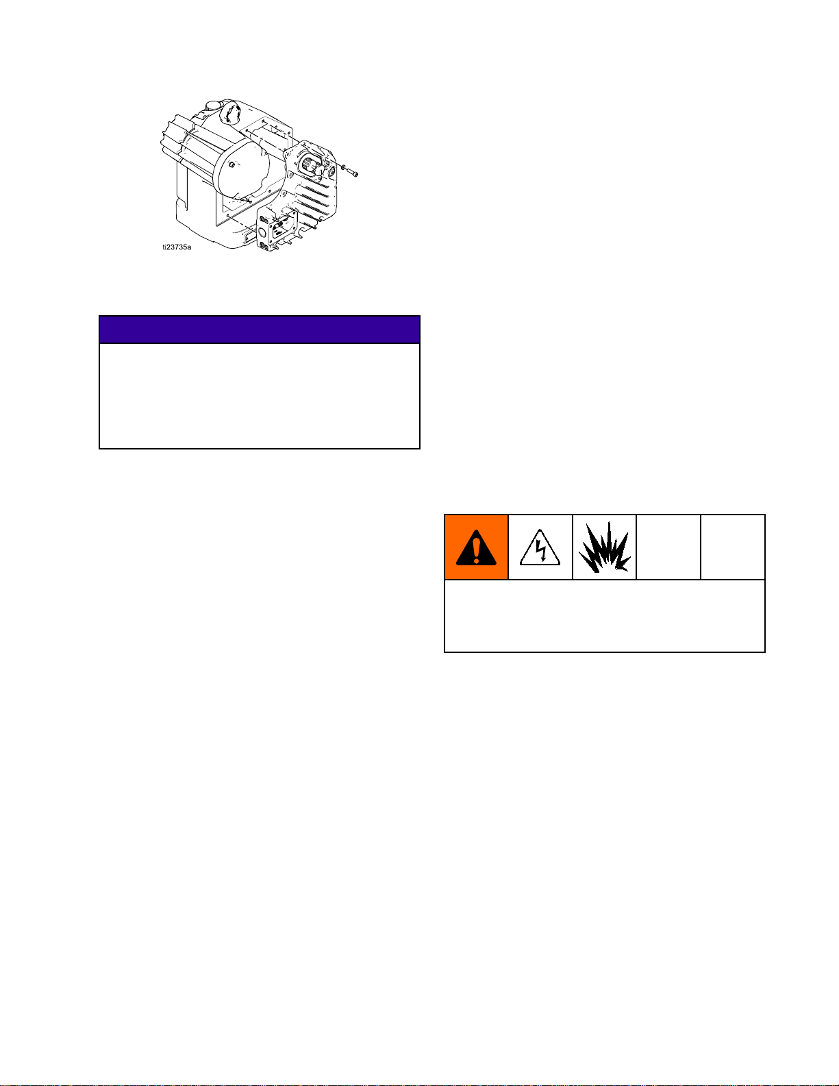
Figure28ElectronicsCover
AdvancedPowerBoardReplacement
tight.Torquesocketheadcapscrewsto15ft-lb
(20Nm).
NOTE:
NOTE: NOTE:
tightening.Thestandoffsshouldbetightened
beforethesocketheadcapscrews.
3.PlugtheCANbuspowerintothepowerbarrier
board.
4.Tightenthetiestraparoundthewirestosecure
themtotheboard.
Putallsixscrewsinplacebefore
Kit 24U939
Disconnect
Disconnect Disconnect
TheCANbusonthepowerbarrierboardis
connectedtothecontrolboardthroughapartition
insidethemotor.Toavoidequipmentdamage,
holdelectronicscoverinplaceuntiltheCANbus
cableisdisconnected.Holdthecoverhorizontally
andtakecarethatthewiresarenotpulledtight.
1.Disconnectbarrierboardpowercablefromthe
controlboard.
2.Removethe4screws(AK)holdingthepartition
(AL)andpowercablebracket(AJ)inplace,set
aside.
3.Removeanytiestrapsthatarepresent.
4.Insertasmallhexkeyintothelowerleftcornerof
thepartitionandpullout.
5.RemovetiestrapconnectingtheCANbuswire
tothepowerbarrierboard(AN).
6.Use1/4”nutdrivertoremovethe4standoffs
(AM)fromthecornersofthepowerbarrierboard,
setaside.
7.Usea5mmhexwrenchtoremovethe2socket
headedcapscrews(AP)fromthepowerbarrier
board,setaside.
8.Removethepowerbarrierboard(AN)fromthe
unit.
Install
Install Install
1.Insertthetiestrapthroughthebackofthepower
2.Putnewpowerbarrierboardinplaceandsecure
New
New New
barrierboard.
usingreservedscrews.Tightenstandoffshand
Power
Power Power
Power
Power Power
Barrier
Barrier Barrier
NOTICE
NOTICE NOTICE
Barrier
Barrier Barrier
Board
Board Board
Board
Board Board
5.Placepartitionbackintoplace.Makecertainthe
notchforthewiresisonthelowerleftsideofthe
partitionandthewiresarenotbeingcrushed.
6.Insertbottomscrewsintothepartitionand
tighten.
7.Placepowerconnectbracketintoplaceand
securewithtwoscrews.
8.Reconnectmotor,temperature,reedswitch,
encoder,andbarrierboardpowerwirestothe
controlboard.
Reinstall
Reinstall Reinstall
Besurethatnowiresarepinchedbetweenthe
electronicscoverandthemotorhousing.Pinched
wiresmaydamagethecontrolboardandwillimpair
explosion-proofsafety.
1.Reinstallelectronicscoverontocenterhousing.
2.Installthe12boltsusinga6mmhexwrench.
NOTE:
NOTE: NOTE:
3.Torquetheboltsto15ft-lb(20Nm).
Reinstall
Reinstall Reinstall
1.Connectwiresfrominsideofwiringbox.Referto
torqueinstructionslistedonplacardinsideofthe
wiringbox.Connectpowercableand/orconduit
totheelectronicscover.
2.Reinstallcoverontowiringbox.
3.Installthe4boltsusinga6mmhexwrench.
NOTE:
NOTE: NOTE:
4.Torquetheboltsto15ft-lb(20Nm).
Electronics
Electronics Electronics
Ensurethelockwashersarestillinplace.
Wiring
Wiring Wiring
Ensurethelockwashersarestillinplace.
Cover
Cover Cover
Box
Cover
Box Box
Cover Cover
3A2526F 35
Page 36

AdvancedPowerBoardReplacement
Kit 24U939
Attach
Attach Attach
1.Connectthecontrolmodulecabletothe
2.Reattachthecontrolmodulemountingbracket
3.Snapthecontrolmoduleintoplaceonthe
Power
Power Power
1.Applypowertotheunittostarttheauto-calibration
2.Themotoroutputshaftwillrunupanddownover
Control
Control Control
electronicscover.
ontotheelectronicscover.
bracket.
Unit
Unit Unit
process.
thecourseofseveralminutes.
Module
Module Module
Bracket
Bracket Bracket
3.Midwaythroughtheauto-calibrationprocessthe
motoroutputshaftwillpauseasitmovestothe
nextstep.
4.Ensuretheauto-calibrationprocessiscomplete
beforecontinuing.
Reattach
Reattach Reattach
1.Jogtheoutputshaftonthepumplowerand
reconnectthecouplingnut.
2.Torquetotheproperlevelpertheappropriate
pumpmanual.
Pump
Pump Pump
Lower
Lower Lower
36 3A2526F
Page 37

AppendixA-SystemControlDrawing24N637
Appendix
Appendix Appendix
NOTES
NOTES NOTES
1.Thenon-intrinsicallysafeterminals(powerrail)
2.Allmotorsmustbebondedtothesamehigh
3.Donotremoveanycoveruntilpowerhasbeen
4.Installationshouldbeinaccordancewith
5.InstallationinCanadashouldbeinaccordance
6.Reservedforfutureuse.
7.Betweenoneandeightmotorsmaybeconnected
8.Therstmotorintheseries(theonewithno
FOR
FOR FOR
mustnotbeconnectedtoanydevicewhichuses
orgeneratesmorethanUm=250Vrmsordc
unlessithasbeendeterminedthatthevoltage
hasbeenadequatelyisolated.
integrityequipotentialsystem.
removed.
ANSI/ISARP12.06.01,installationofintrinsically
safesystemsforhazardous(classied)locations,
andtheNationalElectricalCode(ANSI/NFPA
70).
withtheCanadianElectricalCode,CSAC22.1,
Part1,AppendixF.
inseries.ThemotorsareconnectedwithaCAN
cable(16P911or16P912).Thesideofthecable
withtheredmarkingisconnectedtoPort1of
onemotorandtheunmarkedsideofthecableis
connectedtoPort2ofthenextmotor.
CANcableonPort2)isinstalledwiththepower
jumper24N910connectedtoPort2andPort3.
A
A A
FIG.
16
FIG. FIG.
16 16
System
- --System System
AND
17:
AND AND
17: 17:
Control
Control Control
Drawing
Drawing Drawing
locationoranassociatedISapparatusinthe
non-hazardouslocation.ThesideoftheCAN
cablewiththeredmarkingisconnectedtoPort
1ofthelastmotorandtheunmarkedsideof
thecableisconnectedtotheISorassociated
ISapparatus.
10.TheoutputentityparametersgivenforPins1and
4ineachofPorts1and2arethetotalcurrent
andpoweravailabletobothpinsaddedtogether.
ThecurrentonPin1andPin4addedtogether
willnotexceedthelistedIo,andthepoweroutput
fromPin1andPin4addedtogetherwillnot
exceedthelistedPo.
WARNING:
WARNING: WARNING:
mayimpairintrinsicsafety.
ADVERTISSEMENT:
ADVERTISSEMENT: ADVERTISSEMENT:
decomposantspeutcompromettrela
securiteintrinseque.
Table
Table Table
Calculation
2 22. ..Calculation Calculation
24N637
24N637 24N637
Substitutionofcomponents
Procedures
Procedures Procedures
Zones
Zones Zones
Uo≤Ui
Io≤Ii
Po≤Pi
Co≥Ci+Ccable
Lo≥Li+Lcable
Lo/Ro≥Li/Ri
Lasubstitution
9.The“last”motorintheseriesisconnected
toeitheranISapparatusinthehazardous
3A2526F 37
Page 38

AppendixA-SystemControlDrawing24N637
COMMUNICATION
POWER
1
3
2
COMMUNICATION
POWER
1
3
2
COMMUNICATION
POWER
1
3
2
COMMUNICATION
POWER
1
3
2
COMMUNICATION
POWER
1
3
2
COMMUNICATION
POWER
1
3
2
24N910
IS POWER JUMPER
COMMUNICATION
POWER
1
3
2
ADVANCED COMMUNICATION
MOTOR
EM0012/EM0022
HAZARDOUS LOCATION
HIGH INTEGRITY GROUND
EXPLOSION PROOF
FLAME PROOF
AC POWER
NON-HAZARDOUS
LOCATION
IS
APPARATUS
ASSOCIATED IS
APPARATUS
HAZARDOUS (CLASSIFIED) LOCATION
COMMUNICATION
POWER
1
3
2
ADVANCED COMMUNICATION
MOTOR
EM0012/EM0022
ADVANCED COMMUNICATION
MOTOR
EM0012/EM0022
ADVANCED COMMUNICATION
MOTOR
EM0012/EM0022
ADVANCED COMMUNICATION
MOTOR
EM0012/EM0022
ADVANCED COMMUNICATION
MOTOR
EM0012/EM0022
ADVANCED COMMUNICATION
MOTOR
EM0012/EM0022
ADVANCED COMMUNICATION
MOTOR
EM0012/EM0022
8
9
7
Figure29SystemControlDrawing24N637,Sheet1
38 3A2526F
Page 39

AppendixA-SystemControlDrawing24N637
Figure30SystemControlDrawing24N637,Sheet2
Table
Table Table
Port
Port Port
Port
3:
3 33. ..Port Port
3:
Male
3: 3:
Male Male
Pin
“A”
5 55Pin Pin
“A” “A”
Power
3: 3:
Power Power
M12
M12 M12
Key
Key Key
Barrier
Barrier Barrier
Output
Output Output
Pin
Pin Pin
1
2Power17.96462891681
3
4
5
Parameters
Parameters Parameters
Power
Power Power
CANDataLowNotConnected
CANDataHighNotConnected
Barrier
Barrier Barrier
Units
Units Units
ISGround
Return
Shield
Output
Output Output
Parameters
Parameters Parameters
Voc
Voc Voc
Vmax
Vmax Vmax
—————
—————
Isc
Isc Isc
mA
mA mA
Pt
Pt Pt
mW
mW mW
La
La La
μH
μH μH
Ca
Ca Ca
μF
μF μF
7.7
3A2526F 39
Page 40

AppendixA-SystemControlDrawing24N637
Table
Table Table
Port
Port Port
Port
Port Port
Port
Port Port
Ports
4 44. ..Ports Ports
2:
Male
2: 2:
Male Male
Pin
“B”
5 55Pin Pin
“B” “B”
1:
Male
1: 1:
Male Male
Pin
“A”
5 55Pin Pin
“A” “A”
2:
Male
2: 2:
Male Male
Pin
“B”
5 55Pin Pin
“B” “B”
and
2:
CAN
1 11and and
2: 2:
M12
M12 M12
Key
Key Key
M12
M12 M12
Key
Key Key
M12
M12 M12
Key
Key Key
Data/Power
CAN CAN
Data/Power Data/Power
CAN
CAN CAN
Pin
Pin Pin
1
2VINPower17.972529001280
3
4
5
Pin
Pin Pin
CANDataLowSeeTable5forDatabasedontheNumberofMotors
SignalGround
CANDataHighSeeTable5forDatabasedontheNumberofMotors
CAN
CAN CAN
and
Out
Entity
In InInand and
Units
Units Units
Shield
Data
Data Data
Units
Units Units
Out Out
Data
High/Low
Data Data
High/Low High/Low
High/Low
High/Low High/Low
Parameters
Entity Entity
Parameters Parameters
Input
Loads
Input Input
Loads Loads
Vmax
Vmax Vmax
Vmax
Vmax Vmax
—————
—————
Output
Output Output
Voc
Voc Voc
Vmax
Vmax Vmax
Imax
Imax Imax
mA
mA mA
Barriers
Barriers Barriers
Isc
Isc Isc
mA
mA mA
Pi
Pi Pi
mW
mW mW
Pt
Pt Pt
mW
mW mW
Li
Li Li
μH
μH μH
La
La La
μH
μH μH
Ci
Ci Ci
μF
μF μF
Ca
Ca Ca
μF
μF μF
1
2VINPower17.96462891681
3
Port
1:
Male
Port Port
1: 1:
Pin
5 55Pin Pin
M12
Male Male
M12 M12
“A”
Key
“A” “A”
Key Key
4
5
CANDataLowSeeTable5forDatabasedontheNumberofMotors
SignalGround
CANDataHighSeeTable5forDatabasedontheNumberofMotors
Shield
—————
—————
7.7
40 3A2526F
Page 41

AppendixA-SystemControlDrawing24N637
Table
Table Table
or
or or
to totoany any
Ports
5 55. ..Ports Ports
any
individual
individual individual
Number
Number Number
Motors
Motors Motors
16700900670.2
26700900670.4
36700900670.6
46700900670.8
5
66700900671.2
7
86700900671.6
Number
Number Number
Motors
Motors Motors
14.941027927.31000
and
1 11and and
of
of of
of
of of
Pins
2, 2,2,Pins Pins
pin;
see
pin; pin;
see see
Units
Units Units
Units
Units Units
and
1 11and and
Note
Note Note
CAN
Data
High
and
Low
4: 4:4:CAN CAN
10
10 10
CAN
CAN CAN
Data Data
High High
and and
on
page
on on
CAN
CAN CAN
Vmax
Vmax Vmax
Vmax
Vmax Vmax
Vmax
Vmax Vmax
26)
page page
26) 26)
Data
High/Low
Data Data
High/Low High/Low
Imax
Imax Imax
mA
mA mA
6700900671.0
6700900671.4
Data
High/Low
Data Data
High/Low High/Low
Voc
Voc Voc
Isc
Isc Isc
mA
mA mA
(applies
Low Low
(applies (applies
Input
Loads
Input Input
Loads Loads
Output
Output Output
Barriers
Barriers Barriers
all
CAN
to totoall all
Pi
Pi Pi
mW
mW mW
Pt
Pt Pt
mW
mW mW
data
CAN CAN
data data
μH
μH μH
La
La La
mH
mH mH
pins
shorted
pins pins
shorted shorted
Li
Li Li
together
together together
Ci
Ci Ci
μF
μF μF
Ca
Ca Ca
μF
μF μF
24.941791588.881000
34.942462374.701000
44.943053163.061000
5
64.944074741.721000
7
84.944946321.171000
4.943583952.221000
4.944525531.391000
3A2526F
41
Page 42

MountingHolePattern
Mounting
Mounting Mounting
Hole
Hole Hole
Pattern
Pattern Pattern
A
A A
6.186in.(157mm)6.186in.(157mm)
B
B B
C
C C
Four3/8–16Mounting
Holes
D
D D
Six5/8–11TieRod
Holes:
•8in.(203mm)x120°
boltcircle
OR
•5.9in.(150mm)x
120°boltcircle
42
3A2526F
Page 43

TechnicalData
Technical
Technical Technical
Flo
DC
E EE- --Flo Flo
Input
Input Input
Maximum
Maximum Maximum
pressure:
pressure: pressure:
Maximumcontinuous
cyclerate
Maximum
Maximum Maximum
Powerinletportsize
Ambienttemperature
range
SounddataLessthan70dB(A)
Oilcapacity
OilspecicationGracoPartNo.16W645ISO220silicone-freesyntheticgearoil
Weight99lb45kg
Motors
DC DC
Motors Motors
voltage/Power:
voltage/Power: voltage/Power:
ModelsEM0011,
EM0012,EM0013,
andEM0014
ModelsEM0021,
EM0022,EM0023,
EM0024,EM0025,
andEM0026
potential
potential potential
ModelsEM0011,
EM0012,EM0013,
andEM0014
ModelsEM0021,
EM0022,EM0023,
EM0024,EM0025,
andEM0026
force:
force: force:
ModelsEM0011,
EM0012,EM0013,
andEM0014
ModelsEM0021,
EM0022,EM0023,
EM0024,EM0025,
andEM0026
Data
Data Data
U.S.
U.S. U.S.
100–130/200–240VACsinglephase,50/60Hz,1.4kVA
200–240VAC,singlephase,50/60Hz,2.9kVA
uid
uid uid
218000/v(volumeoflowerincc)=psi1500/v(volumeoflowerincc)=bar
436000/v(volumeoflowerincc)=psi3000/v(volumeoflowerincc)=bar
20cpm
1400lbf
2800lbf
3/4–14npt(f)
32–104°F0–40°C
1.5quarts1.4liters
Metric
Metric Metric
6227N
12455N
3A2526F 43
Page 44

Graco
Graco Graco
GracowarrantsallequipmentreferencedinthisdocumentwhichismanufacturedbyGracoandbearingits
nametobefreefromdefectsinmaterialandworkmanshiponthedateofsaletotheoriginalpurchaserfor
use.Withtheexceptionofanyspecial,extended,orlimitedwarrantypublishedbyGraco,Gracowill,fora
periodoftwelvemonthsfromthedateofsale,repairorreplaceanypartoftheequipmentdetermined
byGracotobedefective.Thiswarrantyappliesonlywhentheequipmentisinstalled,operatedand
maintainedinaccordancewithGraco’swrittenrecommendations.
Thiswarrantydoesnotcover,andGracoshallnotbeliableforgeneralwearandtear,oranymalfunction,
damageorwearcausedbyfaultyinstallation,misapplication,abrasion,corrosion,inadequateorimproper
maintenance,negligence,accident,tampering,orsubstitutionofnon-Gracocomponentparts.Norshall
Gracobeliableformalfunction,damageorwearcausedbytheincompatibilityofGracoequipment
withstructures,accessories,equipmentormaterialsnotsuppliedbyGraco,ortheimproperdesign,
manufacture,installation,operationormaintenanceofstructures,accessories,equipmentormaterials
notsuppliedbyGraco.
Thiswarrantyisconditionedupontheprepaidreturnoftheequipmentclaimedtobedefectivetoan
authorizedGracodistributorforvericationoftheclaimeddefect.Iftheclaimeddefectisveried,Graco
willrepairorreplacefreeofchargeanydefectiveparts.Theequipmentwillbereturnedtotheoriginal
purchasertransportationprepaid.Ifinspectionoftheequipmentdoesnotdiscloseanydefectinmaterial
orworkmanship,repairswillbemadeatareasonablecharge,whichchargesmayincludethecostsof
parts,labor,andtransportation.
THISWARRANTYISEXCLUSIVE,ANDISINLIEUOFANYOTHERWARRANTIES,EXPRESSOR
IMPLIED,INCLUDINGBUTNOTLIMITEDTOWARRANTYOFMERCHANTABILITYORWARRANTY
OFFITNESSFORAPARTICULARPURPOSE.
Graco’ssoleobligationandbuyer’ssoleremedyforanybreachofwarrantyshallbeassetforthabove.
Thebuyeragreesthatnootherremedy(including,butnotlimitedto,incidentalorconsequentialdamages
forlostprots,lostsales,injurytopersonorproperty,oranyotherincidentalorconsequentialloss)shall
beavailable.Anyactionforbreachofwarrantymustbebroughtwithintwo(2)yearsofthedateofsale.
GRACO
GRACO GRACO
MERCHANTABILITY
MERCHANTABILITY MERCHANTABILITY
ACCESSORIES,
ACCESSORIES, ACCESSORIES,
GRACO.
GRACO. GRACO.
aresubjecttothewarranty,ifany,oftheirmanufacturer.Gracowillprovidepurchaserwithreasonable
assistanceinmakinganyclaimforbreachofthesewarranties.
InnoeventwillGracobeliableforindirect,incidental,specialorconsequentialdamagesresultingfrom
Gracosupplyingequipmenthereunder,orthefurnishing,performance,oruseofanyproductsorother
goodssoldhereto,whetherduetoabreachofcontract,breachofwarranty,thenegligenceofGraco,or
otherwise.
FORGRACOCANADACUSTOMERS
ThePartiesacknowledgethattheyhaverequiredthatthepresentdocument,aswellasalldocuments,
noticesandlegalproceedingsenteredinto,givenorinstitutedpursuantheretoorrelatingdirectlyor
indirectlyhereto,bedrawnupinEnglish.Lespartiesreconnaissentavoirconvenuquelarédactiondu
présentedocumentseraenAnglais,ainsiquetousdocuments,avisetprocéduresjudiciairesexécutés,
donnésouintentés,àlasuitedeouenrapport,directementouindirectement,aveclesprocédures
concernées.
MAKES
MAKES MAKES
Theseitemssold,butnotmanufacturedbyGraco(suchaselectricmotors,switches,hose,etc.),
Standard
Standard Standard
NO
WARRANTY,
NO NO
WARRANTY, WARRANTY,
AND
FITNESS
AND AND
EQUIPMENT,
EQUIPMENT, EQUIPMENT,
FITNESS FITNESS
MATERIALS
MATERIALS MATERIALS
Warranty
Warranty Warranty
AND
DISCLAIMS
AND AND
DISCLAIMS DISCLAIMS
FOR
FOR FOR
PARTICULAR
A AAPARTICULAR PARTICULAR
OR
OR OR
ALL
IMPLIED
ALL ALL
IMPLIED IMPLIED
PURPOSE,
COMPONENTS
COMPONENTS COMPONENTS
PURPOSE, PURPOSE,
WARRANTIES
WARRANTIES WARRANTIES
IN
CONNECTION
IN IN
SOLD
SOLD SOLD
CONNECTION CONNECTION
BUT
NOT
BUT BUT
NOT NOT
OF
OF OF
WITH
MANUFACTURED
MANUFACTURED MANUFACTURED
WITH WITH
BY
BY BY
Graco
Graco Graco
ForthelatestinformationaboutGracoproducts,visitwww.graco.com.Forpatentinformation,see
www.graco.com/patents.
To
To To
Phone:
Phone: Phone:
Allwrittenandvisualdatacontainedinthisdocumentreectsthelatestproductinformationavailableatthetimeofpublication.
place
place place
612-623-6921or or
GRACO
GRACO GRACO
Information
Information Information
an
order,
an an
order, order,
contactyourGracoDistributororcalltoidentifythenearestdistributor.
or
Toll
Free:
Toll Toll
Free: Free:
1-800-328-0211Fax: Fax:
Gracoreservestherighttomakechangesatanytimewithoutnotice.
OriginalInstructions.ThismanualcontainsEnglish,MM3A2526
International
International International
INC.
AND
INC. INC.
Copyright
Copyright Copyright
SUBSIDIARIES
AND AND
SUBSIDIARIES SUBSIDIARIES
2012,
Graco
2012, 2012,
Graco Graco
Graco
Graco Graco
Ofces:
Ofces: Ofces:
Inc.
All
Inc. Inc.
Graco
All All
Graco Graco
RevisionF,December2014
Headquarters:
Headquarters: Headquarters:
P.O.
• ••P.O. P.O.
www.graco.com
Fax:
612-378-3505
Minneapolis
Belgium,China,Japan,Korea
BOX
1441
BOX BOX
manufacturing
manufacturing manufacturing
1441 1441
MINNEAPOLIS,
• ••MINNEAPOLIS, MINNEAPOLIS,
locations
locations locations
are
are are
MN
55440-1441
MN MN
registered
registered registered
55440-1441 55440-1441
ISO
9001.
to totoISO ISO
9001. 9001.
USA
• ••USA USA
 Loading...