

Page 1
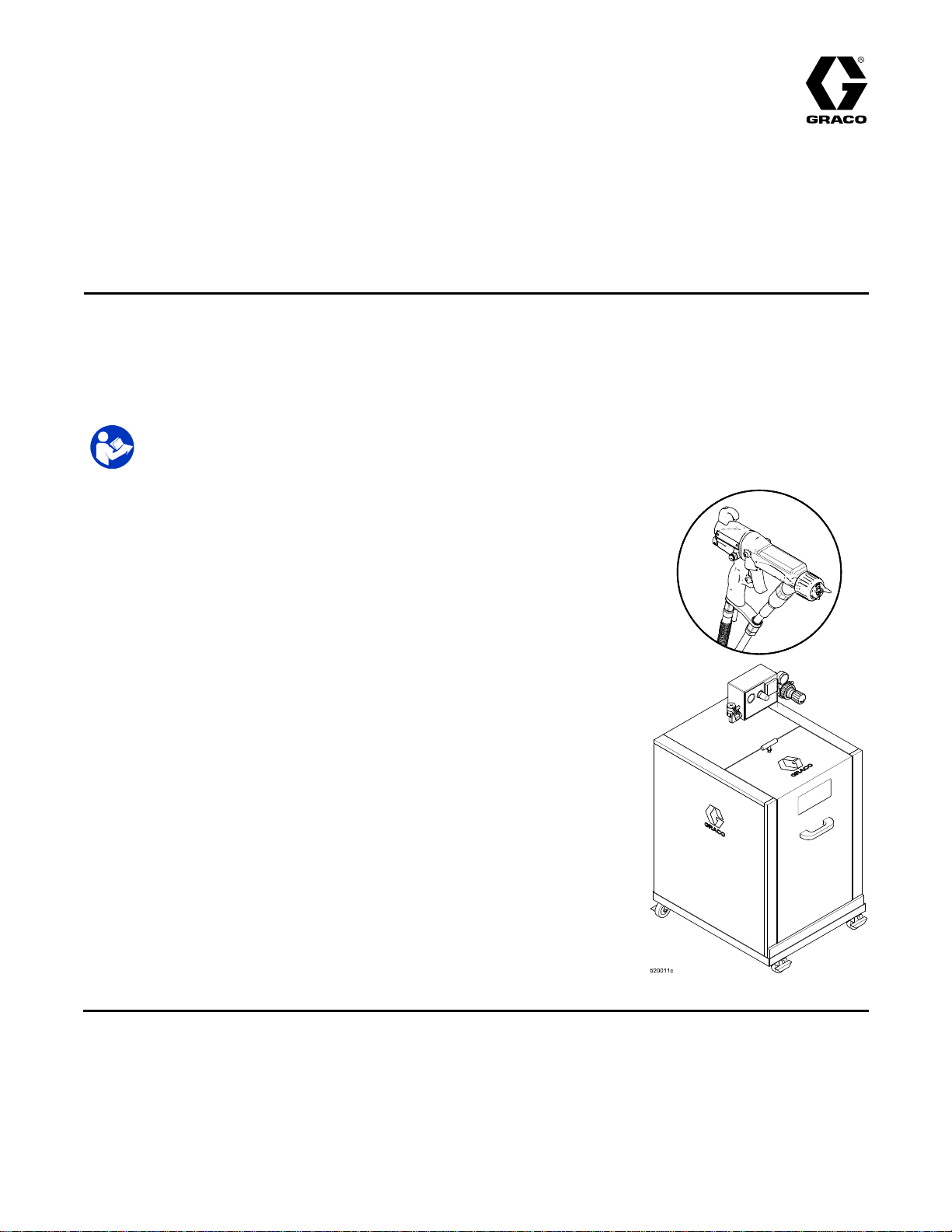
Instructions-Parts
WB3000
WB3000 WB3000
60
AA
60 60
AA AA
Air
assisted
Air Air
- --assisted assisted
meet
at
meet meet
For
For For
3000psi(21MPa,210bar)Maximum
FluidWorkingPressure
100psi(0.7MPa,7bar)MaximumAir
WorkingPressure
Seepage3formodelpartnumbersand
approvalinformation.
least
at at
least least
professional
professional professional
Important
Important Important
Readallwarningsandinstructionsinthismanualbeforeusingthe
equipment.Save Save
Isolation
Isolation Isolation
WB
WB WB
spray
spray spray
one
one one
Gun
Gun Gun
system
system system
of
of of
use
use use
Safety
Safety Safety
Save
for
for for
the
conditions
the the
conditions conditions
only.
only. only.
Instructions
Instructions Instructions
these
these these
System
System System
&
Pro
& &
Pro Pro
Xp™
Xp™ Xp™
3A2497H
EN
use
when
use use
instructions.
instructions. instructions.
electrostatically
when when
electrostatically electrostatically
for
non
for for
ammability
non non
- --ammability ammability
spraying
spraying spraying
listed
listed listed
conductive,
conductive, conductive,
on
page
on on
3.
page page
3. 3.
waterborne
waterborne waterborne
uids
that
uids uids
that that
PROVENQUALITY.LEADINGTECHNOLOGY.
Page 2

Contents
Contents Contents
Models...............................................................3
RelatedManuals................................................3
Warnings...........................................................4
GunOverview....................................................7
HowtheElectrostaticAASprayGun
Works............................................7
SprayingWaterborneFluids
Electrostatically..............................7
Controls,Indicators,andComponents...........8
SmartGuns.................................................9
Installation..........................................................14
SystemRequirements..................................14
WarningSign...............................................14
InstalltheSystem.........................................14
VentilatetheSprayBooth.............................14
AirSupplyLine............................................15
GroundtheCabinet......................................15
Grounding...................................................16
ConnecttheWaterborneFluidHose..............18
AgitatorKitAccessory..................................22
GunSetup..........................................................23
GunSetupProcedure...................................23
CheckGunElectricalGrounding...................26
FlushBeforeUsingEquipment......................27
Operation...........................................................28
PressureReliefProcedure............................28
OperatingChecklist......................................29
FluidVoltageDischargeandGrounding
Procedure......................................29
FilltheFluidSupply......................................30
Startup........................................................30
Shutdown....................................................30
Maintenance......................................................31
DailyCareandCleaningChecklist................31
Flushing......................................................31
CleantheGunDaily.....................................33
DailySystemCare.......................................35
ElectricalTests...................................................36
TestGunResistance....................................36
TestPowerSupplyResistance.....................37
TestGunBarrelResistance..........................37
TestGroundStripResistance.......................38
TestCylinderResistance..............................38
Troubleshooting..................................................39
VoltageLossTroubleshooting.......................39
SprayPatternTroubleshooting......................41
GunOperationTroubleshooting....................42
ElectricalTroubleshooting............................43
Repair................................................................44
PreparetheGunforService.........................44
AirCap,SprayTip,andFluidSeatHousing
Replacement..................................44
ElectrodeReplacement................................45
GunBarrelRemoval.....................................46
GunBarrelInstallation..................................46
FluidNeedleReplacement............................47
PowerSupplyRemovaland
Replacement..................................48
AlternatorRemovalandReplacement...........49
FanAirAdjustmentValveRepair..................51
AtomizingAirAdjustmentValve
Repair............................................51
ESOn-OffValveRepair...............................52
AirValveRepair...........................................53
SmartModuleReplacement..........................53
AirSwivelandExhaustValve
Replacement..................................54
Parts..................................................................55
StandardAir-AssistedSprayGun
Assembly.......................................55
SmartAir-AssistedSprayGun
Assembly.......................................57
IsolationEnclosure.......................................59
TubingandWiring.......................................62
AlternatorAssembly.....................................64
ESOn-OffValveAssembly...........................65
FanAirAdjustmentValveAssembly..............66
AirCapAssembly........................................66
SmartModuleAssembly...............................67
SprayTipSelectionChart....................................68
AEMFineFinishSprayTips..........................68
AEFFineFinishPre-OriceSpray
Tips...............................................69
RoundSprayTips........................................69
RepairKitsandAccessories................................70
GunAccessories..........................................70
OperatorAccessories...................................71
SystemAccessories.....................................71
Signs..........................................................71
TestEquipment...........................................71
Hoses.........................................................71
245895AgitatorKit......................................72
IgnitabilityofCoatingMaterials............................73
Dimensions........................................................74
TechnicalSpecications......................................75
CaliforniaProposition65.....................................75
2
3A2497H
Page 3
Models
Models
Models Models
Models
Models Models
Part
Part Part
24N551WB3000WaterborneIsolationEnclosure24N550withstandard
24P632WB3000WaterborneIsolationEnclosure24N550withsmartelectrostatic
24N550WB3000
H60T18ProXp60AAWB
which
are
FM
which which
are are
No.
No. No.
Approved
FM FM
Approved Approved
FM
FM FM
• ••Material Material
Models
Models Models
criteria:
criteria: criteria:
• ••Material Material
and
Compliant
and and
Compliant Compliant
approved
approved approved
Material
for
Sustained
for for
Sustained Sustained
Material
For
more
For For
more more
Model
Model Model
for
for for
does
does does
Compliant
Compliant Compliant
classied
is isisclassied classied
information,
information, information,
with
EN50059
with with
EN50059 EN50059
use
with
uids
that
meet
the
use use
with with
uids uids
that that
meet meet
not
sustain
not not
sustain sustain
Burning
Burning Burning
with
with with
Description
Description Description
electrostaticair-assistedspraygunH60T18,groundedairhose
235070,andunshieldedwaterborneuidhose24M508.
air-assistedspraygunH60M18,groundedairhose235070,
andunshieldedwaterborneuidhose24M508.
WaterborneIsolationEnclosureforunshieldedhoses.Doesnot
includehosesandgun.
StandardElectrostaticAir-assistedSprayGun,forwaterborne
coatings.
burning
burning burning
Liquid
of ofofLiquid Liquid
EN
50059
EN EN
50059 50059
as
non
as as
ignitable
non non
- --ignitable ignitable
see
Ignitability
see see
Ignitability Ignitability
accordance
in ininaccordance accordance
Mixtures,
Mixtures, Mixtures,
when
when when
following
the the
following following
ASTM
ASTM ASTM
used
with
used used
with with
as
dened
as as
dened dened
Coating
of ofofCoating Coating
condition:
condition: condition:
with
with with
D4206.
D4206. D4206.
uids
uids uids
by
EN
by by
EN EN
Materials,
Materials, Materials,
the
Standard
the the
Standard Standard
that
meet
that that
meet meet
50059:
50059: 50059:
page
page page
Test
Method
Test Test
Method Method
the
following
the the
following following
2018.
2018. 2018.
73
.
73 73
. .
H60M18ProXp60AAWB
25R012
25R014
Related
Related Related
Manual
Manual Manual
3A2498
307263ProbeandMeter,Instructions
309455TestFixture,HighVoltageProbe,andkVMeter,Instructions
406999
No.
No. No.
Manuals
Manuals Manuals
Description
Description Description
RoundSprayKit,Instructions
VoltageTesterConversionKit,Instructions
-------
-------
SmartElectrostaticAir-assistedSprayGun,forwaterborne
coatings.
WaterborneFluidHoseAssembly,25ft(7.6m)
WaterborneFluidHoseAssembly,50ft(15.2m)
3A2497H3
Page 4
Warnings
Warnings
Warnings Warnings
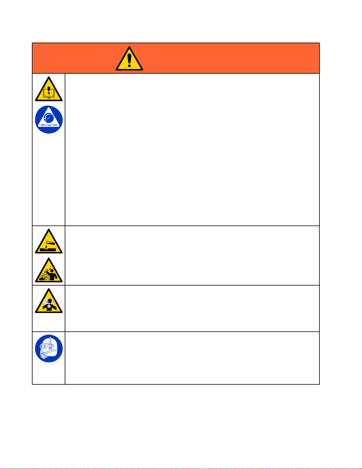
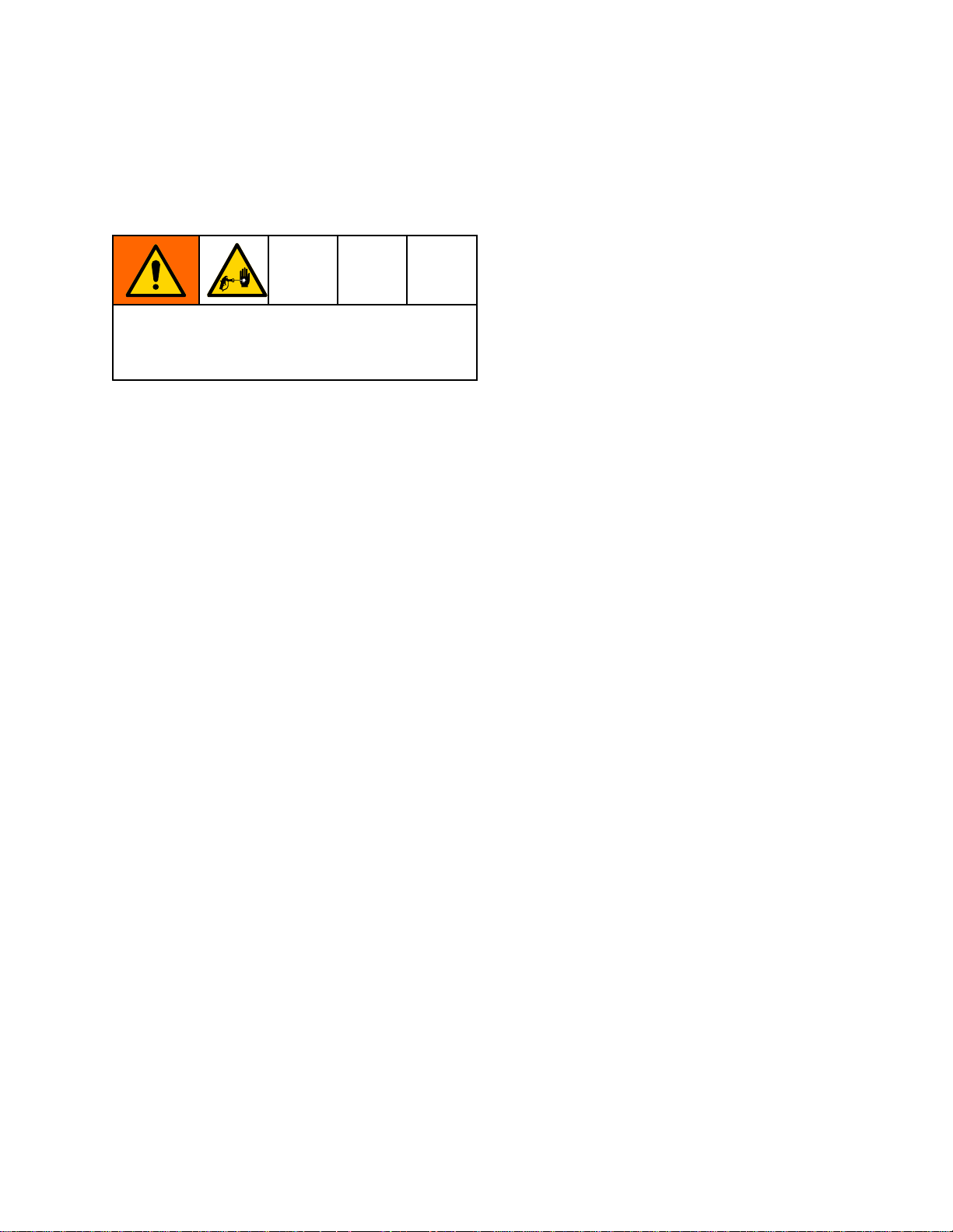
Thefollowingwarningsareforthesetup,use,grounding,maintenance,andrepairofthisequipment.The
exclamationpointsymbolalertsyoutoageneralwarningandthehazardsymbolsrefertoprocedure-specic
risks.Whenthesesymbolsappearinthebodyofthismanualoronwarninglabels,referbacktothese
Warnings.Product-specichazardsymbolsandwarningsnotcoveredinthissectionmayappearthroughout
thebodyofthismanualwhereapplicable.
WARNING
WARNING WARNING
FIRE
AND
FIRE FIRE
Combustibledustinwork work
•Fluidsusedmustmeetthefollowingammabilityrequirements:
Stop
•Stop Stop
equipmentuntilyouidentifyandcorrecttheproblem.
•Checkgunresistance,hoseresistance,andelectricalgroundingdaily.
•Useandcleanequipmentonlyinwellventilatedarea.
•Interlockthegunairsupplytopreventoperationunlessventilatingfansareon.
•Onlyusenon-ammablesolventswhenushingorcleaningequipment.
•Alwaysturntheelectrostaticsoffwhenushing,cleaningorservicingequipment.
•Eliminateallignitionsources;suchaspilotlights,cigarettes,portableelectriclamps,and
plasticdropcloths(potentialstaticarc).
•Donotplugorunplugpowercordsorturnlightsonoroffwhenammablefumesarepresent.
•Keepsprayareafreeofdebris,includingsolvent,ragsandgasoline.
•Keepaworkingreextinguisherintheworkarea.
EXPLOSION
AND AND
EXPLOSION EXPLOSION
FM,
FMc
•FM, FM,
MaterialdoesnotsustainburninginaccordancewiththeStandardTestMethodfor
SustainedBurningofLiquidMixtures,ASTMD4206.
CE
•CE CE
Materialisclassiedasnon-ignitableasdenedbyEN50059:2018.
operation
operation operation
Approved:
FMc FMc
Approved: Approved:
EN
50059
- --EN EN
50059 50059
immediately
immediately immediately
HAZARD
HAZARD HAZARD
work
area
area area
canigniteorexplode.Tohelppreventreandexplosion:
Compliant:
Compliant: Compliant:
ifstaticsparkingoccursoryoufeelashock.Donotuse
4
3A2497H
Page 5
Warnings
WARNING
WARNING WARNING
ELECTRIC
ELECTRIC ELECTRIC
Impropergrounding,setup,orusageofanisolatedwaterbornesystemcanresultinelectric
shock.Tohelppreventelectricshock:
•Groundallequipment,personnel,objectbeingsprayed,andconductiveobjectsinorclose
tosprayarea.SeeGrounding Grounding
•Connecttheelectrostaticguntoavoltageisolationsystemthatwilldischargethesystem
voltagewhennotinuse.
•Allcomponentsoftheisolationsystemthatarechargedtohighvoltagemustbecontained
withinanisolationenclosurethatpreventspersonnelfrommakingcontactwiththehigh
voltagecomponentsbeforethesystemvoltageisdischarged.
•FollowtheFluid Fluid
thevoltage;beforecleaning,ushing,orservicingthesystem;beforeapproachingthefrontof
thegun;andbeforeopeningtheisolationenclosurefortheisolateduidsupply.
•Donotenterahighvoltageorhazardousareauntilallhighvoltageequipmenthasbeen
discharged.
•Donottouchthegunnozzleorelectrode,orcomewithin4in.(102mm)oftheelectrode
duringgunoperation.FollowtheFluid Fluid
•Interlockthegunairsupplywiththevoltageisolationsystemtoshutofftheairsupplyanytime
theisolationsystemenclosureisopened.
•Onlyusethered-coloredGracoelectricallyconductivegunairhosewiththisgun.Donot
useblackorgray-coloredGracoairhoses.
•Donotsplicehosestogether.InstallonlyonecontinuousGracowaterborneuidhose
betweentheisolateduidsupplyandthespraygun.
SKIN
SKIN SKIN
High-pressureuidfromgun,hoseleaks,orrupturedcomponentswillpierceskin.Thismay
looklikejustacut,butitisaseriousinjurythatcanresultinamputation.Get Get
treatment.
treatment. treatment.
SHOCK
SHOCK SHOCK
Fluid
INJECTION
INJECTION INJECTION
HAZARD
HAZARD HAZARD
Grounding
Voltage
Voltage Voltage
HAZARD
HAZARD HAZARD
instructions.
Discharge
Discharge Discharge
and
Grounding
and and
Grounding Grounding
Fluid
Voltage
Voltage Voltage
Procedure
Procedure Procedure
Discharge
Discharge Discharge
and
and and
wheninstructedtodischarge
Grounding
Grounding Grounding
Procedure
Procedure Procedure
Get
immediate
immediate immediate
.
surgical
surgical surgical
•Donotspraywithouttipguardandtriggerguardinstalled.
•Engagetriggerlockwhennotspraying.
•Donotpointgunatanyoneoratanypartofthebody.
•Donotputyourhandoverthespraytip.
•Donotstopordeectleakswithyourhand,body,glove,orrag.
•FollowthePressure Pressure
orservicingequipment.
•Tightenalluidconnectionsbeforeoperatingtheequipment.
•Checkhosesandcouplingsdaily.Replacewornordamagedpartsimmediately.
Pressure
Relief
Procedure
Relief Relief
Procedure Procedure
whenyoustopsprayingandbeforecleaning,checking,
3A2497H5
Page 6
Warnings
WARNING
WARNING WARNING
EQUIPMENT
EQUIPMENT EQUIPMENT
Misusecancausedeathorseriousinjury.
•Donotoperatetheunitwhenfatiguedorundertheinuenceofdrugsoralcohol.
•Donotexceedthemaximumworkingpressureortemperatureratingofthelowestrated
systemcomponent.SeeTechnical Technical
•Useuidsandsolventsthatarecompatiblewithequipmentwettedparts.SeeTechnical Technical
Specications
Specications Specications
Forcompleteinformationaboutyourmaterial,requestaSafetyDataSheet(SDS)from
yourdistributororretailer.
•Donotleavetheworkareawhileequipmentisenergizedorunderpressure.
•TurnoffallequipmentandfollowthePressure Pressure
•Checkequipmentdaily.Repairorreplacewornordamagedpartsimmediatelywithgenuine
manufacturer’sreplacementpartsonly.
•Donotalterormodifyequipment.Alterationsormodicationsmayvoidagencyapprovals
andcreatesafetyhazards.
•Makesureallequipmentisratedandapprovedfortheenvironmentinwhichyouareusingit.
•Useequipmentonlyforitsintendedpurpose.Callyourdistributorforinformation.
•Routehosesandcablesawayfromtrafcareas,sharpedges,movingparts,andhotsurfaces.
•Donotkinkoroverbendhosesorusehosestopullequipment.
•Keepchildrenandanimalsawayfromworkarea.
•Complywithallapplicablesafetyregulations.
PLASTIC
PLASTIC PLASTIC
Manysolventscandegradeplasticpartsandcausethemtofail,whichcouldcauseserious
injuryorpropertydamage.
MISUSE
MISUSE MISUSE
PARTS
PARTS PARTS
HAZARD
HAZARD HAZARD
Technical
inallequipmentmanuals.Readuidandsolventmanufacturer’swarnings.
CLEANING
CLEANING CLEANING
SOLVENT
SOLVENT SOLVENT
Specications
Specications Specications
Pressure
HAZARD
HAZARD HAZARD
Relief
Relief Relief
inallequipmentmanuals.
Procedure
Procedure Procedure
whenequipmentisnotinuse.
Technical
•Useonlycompatiblewater-basedsolventstocleanplasticstructuralorpressure-containing
parts.
•SeeTechnical Technical
TOXIC
TOXIC TOXIC
Toxicuidsorfumescancauseseriousinjuryordeathifsplashedintheeyesoronskin,
inhaled,orswallowed.
•ReadSafetyDataSheets(SDS)toknowthespecichazardsoftheuidsyouareusing.
•Storehazardousuidinapprovedcontainers,anddisposeofitaccordingtoapplicable
PERSONAL
PERSONAL PERSONAL
Wearappropriateprotectiveequipmentwhenintheworkareatohelppreventseriousinjury,
includingeyeinjury,hearingloss,inhalationoftoxicfumes,andburns.Thisprotective
equipmentincludesbutisnotlimitedto:
•Protectiveeyewear,andhearingprotection.
•Respirators,protectiveclothing,andglovesasrecommendedbytheuidandsolvent
Technical
andsolventmanufacturer’sSafetyDataSheet(SDS)andrecommendations.
FLUID
FLUID FLUID
guidelines.
manufacturer.
Specications
Specications Specications
OR
FUMES
OR OR
FUMES FUMES
PROTECTIVE
PROTECTIVE PROTECTIVE
inthisandallotherequipmentinstructionmanuals.Readuid
EQUIPMENT
EQUIPMENT EQUIPMENT
63A2497H
Page 7
GunOverview
Gun
Gun Gun
How
How How
Works
Works Works
Thisisnotanairspraygun.Tohelpprevent
seriousinjuryfrompressurizeduid,suchasskin
injection,andsplashinguid,readandfollowthe
Skin
Skin Skin
Theair-assistedsprayguncombinesairlessand
airsprayingconcepts.Thespraytipatomizes
andshapestheuidintoafanpattern,asdoes
aconventionalairlessspraytip.Airfromtheair
capfurtheratomizestheuidandcompletesthe
atomizationoftheuidtailstoproduceauniform
pattern.
Asthegunistriggered,partoftheregulatedair
operatesthealternatorturbineandtherestofthe
airhelpsatomizetheuidbeingsprayed.The
alternatorgeneratespower,whichisconvertedby
thepowercartridgetosupplyhighvoltagetothe
gun’selectrode.
Thegun’sinternalpowersupplyprovideshigh
voltage.Theuidiselectrostaticallychargedasit
passestheelectrode.Thechargeduidisattracted
tothegroundedworkpiece,wrappingaroundand
evenlycoatingallsurfaces.
Theregulatedairthatisdirectedtotheaircapcan
befurthercontrolledusingthegun’satomizingair
adjustmentvalve.Thisvalvecanbeusedtorestrict
airowtotheaircapwhilemaintainingsufcientair
owtothealternator.Theatomizingairadjustment
valvedoesnotcontrolpatternwidth.Tochange
patternwidth,useanewtipsize,orusethefan
adjustmenttonarrowthepatternwidth.
Thehighworkinguidpressureofthisgunprovides
thepowerneededtoatomizehighersolidsmaterials.
Overview
Overview Overview
the
Electrostatic
the the
Electrostatic Electrostatic
Injection
Injection Injection
Note
Forairlessatomization,ifdesired,turn
thegun’satomizingairadjustmentvalve
completelyoff.Closingthisvalvedoesnot
affectalternatoroperation.
Hazard
Hazard Hazard
Warnings
Warnings Warnings
AA
AA AA
Spray
Spray Spray
onpage5.
Gun
Gun Gun
Spraying
Spraying Spraying
Electrostatically
Electrostatically Electrostatically
Thiselectrostaticair-assistedspraygunisdesigned
tosprayonly only
followingammabilityrequirements:
FM,
FMc
•FM, FM,
FMc FMc
Materialdoesnotsustainburninginaccordance
withtheStandardTestMethodforSustained
BurningofLiquidMixtures,ASTMD4206.
CE-EN
•CE-EN CE-EN
•Materialisclassiedasnon-ignitableasdenedby
EN50059:2018.
Formoreinformation,see
IgnitabilityofCoatingMaterials,page73.
Whenconnectedtoavoltageisolationsystem,
alloftheuidinthespraygun,uidhose,and
isolateduidsupplyischargedtohighvoltage,
whichmeansthatthesystemhasmoreelectrical
energythanasolvent-basedsystem.Therefore,
onlynon-ammableuids(asdenedunder
Models,page3)canbesprayedwiththesystemor
beusedtoclean,ush,orpurgethesystem.
Precautionsmustbetakenwhenusingelectrostatic
waterborneequipmenttoavoidpotentialshock
hazards.Whenthespraygunchargestheisolated
uidtohighvoltage,itissimilartocharginga
capacitororabattery.Thesystemwillstoresomeof
theenergywhilesprayingandretainsomeofthat
energyafterthespraygunisshutoff.Donottouch
thegunnozzleorcomewithin4in.(102mm)of
theelectrodeuntilthestoredenergyisdischarged.
Theamountoftimeittakestodischargethe
energydependsonthesystemdesign.Followthe
FluidVoltageDischargeandGroundingProcedure,
page29beforeapproachingthefrontofthegun.
TheGracowarrantyandapprovalsarevoidifthe
electrostaticspraygunisconnectedtoanon-Graco
voltageisolationsystemorifthegunisoperated
above60kV.
Waterborne
Waterborne Waterborne
only
waterborneuidswhichmeetthe
Approved:
Approved: Approved:
50059
50059 50059
Compliant:
Compliant: Compliant:
Fluids
Fluids Fluids
3A2497H
7
Page 8
GunOverview
Controls,
Controls, Controls,
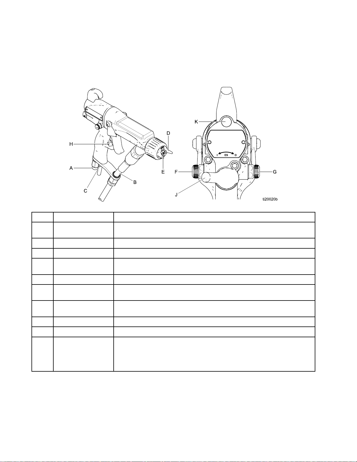
Theelectrostaticgunincludesthefollowing
controls,indicators,andcomponents(seeFig.
1).ForinformationonSmartguns,alsosee
SmartGuns,page9.
Figure1GunOverview
Indicators,
Indicators, Indicators,
and
Components
and and
Components Components
Item
Item Item
A
BFluidHose
C
D
EElectrode
FFanAirAdjustment
G
H
J
K
Description
Description Description
AirSwivelInlet1/4npsm(m)left-handthread,forGracored-coloredgroundedairsupply
TurbineAirExhaust
AirCap/TipGuard
andSprayTip
Valve
AtomizingAir
AdjustmentValve
TriggerSafetyLockLockstriggertopreventgunfromspraying.
ESOn-OffValveTurnselectrostaticsON(I)orOFF(O).
ESIndicator(standardgunonly;for
Smartgunindicator,
seeOperatingMode,
page9)
Purpose
Purpose Purpose
hose.
Gracowaterborneuidhose
Barbedtting,forsuppliedexhausttube.
SeeSprayTipSelectionChart,page68,foravailablesizes.
Supplieselectrostaticchargetotheuid.
Adjustsfansizeandshape.Canbeusedtodecreasepatternwidth.
Adjustsatomizingairow.
LitwhenESisON(I).Colorindicatesalternatorfrequency.SeetheLED
indicatortableinGunSetup,page23.
83A2497H
Page 9
GunOverview
Smart
Smart Smart
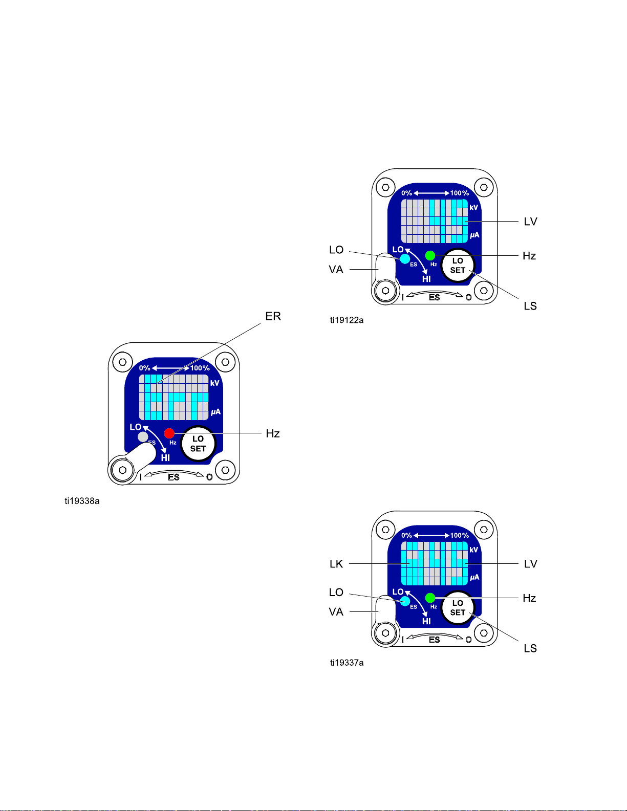
TheSmartGunmoduledisplayssprayingvoltage,
current,alternatorspeed,andthevoltagesetting(low
orhigh).Italsoallowstheusertochangetoalower
sprayingvoltage.Themodulehastwomodes:
•OperatingMode
•DiagnosticMode
Operating
Operating Operating
Bar
Bar Bar
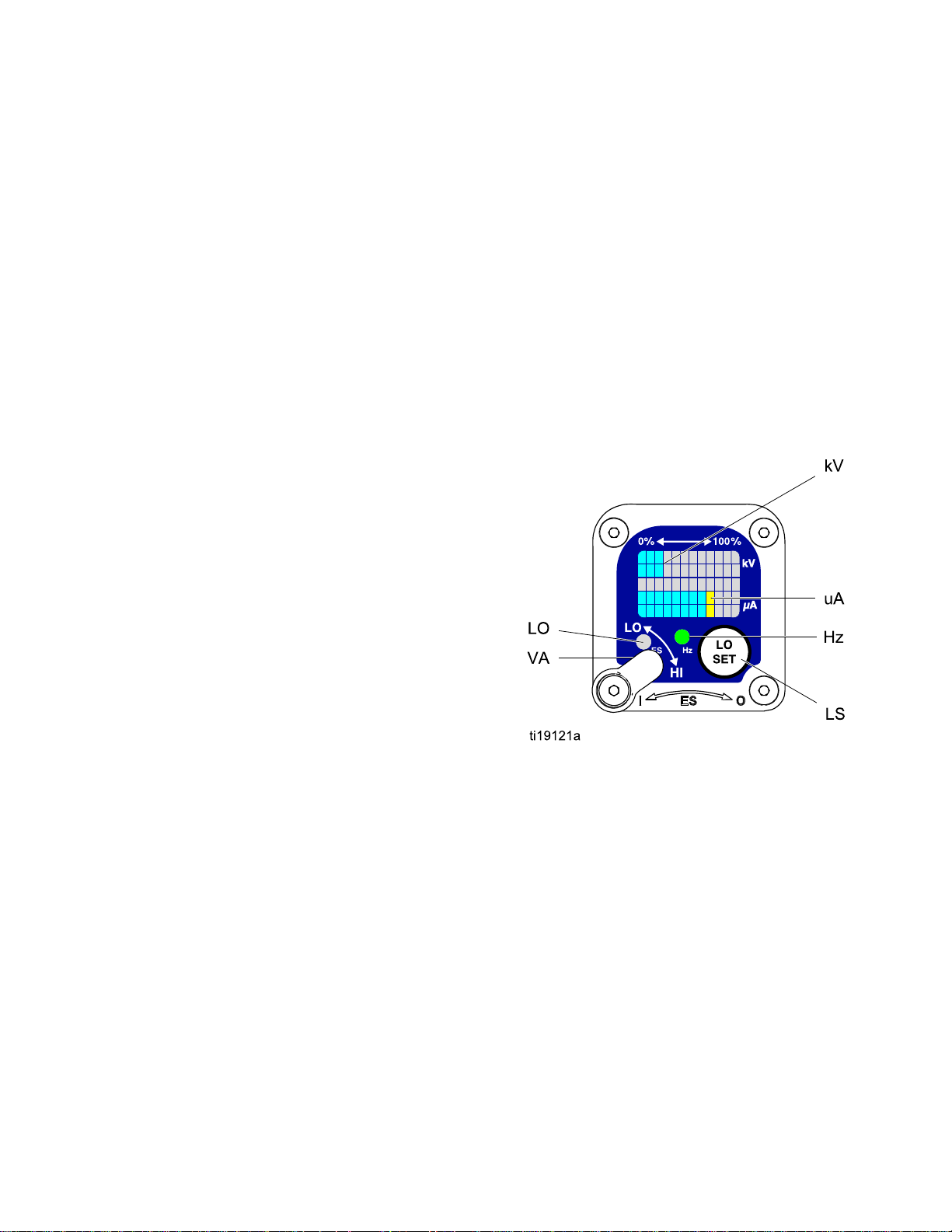
SeeFig.2andSmartGunKey,page11.The
OperatingModedisplaysgundataduringnormal
spraying.Thedisplayusesabargraphtoshowthe
voltagelevelinkiloVolts(kV)andthecurrentlevelin
microAmperes(uA).Thebargraphrangeisfrom0
to100%foreachvalue.
IftheuAbargraphLEDsareblue,thegunisready
tospray.IftheLEDsareyelloworred,thecurrentis
toohigh.SeeElectricalTroubleshooting,page43.
Guns
Guns Guns
Mode
Mode Mode
Graph
Graph Graph
Voltage
Voltage Voltage
Thevoltageadjustmentswitch(VA)allowsthe
operatortochangefromlowtohighvoltage.
•Thehighvoltagesettingisdeterminedbythe
maximumvoltageofthegunandisnotadjustable.
•Thelowvoltageindicator(LO)lights
whentheswitchissettoLO.Thelow
voltagesettingisuseradjustable.See
AdjustingtheLowVoltageSetting,page10.
Adjustment
Adjustment Adjustment
Note
IftheErrordisplayappears,theSmart
modulehaslostcommunicationwiththe
powersupply.SeeErrorDisplay,page10for
furtherinformation.
Switch
Switch Switch
Hz
Indicator
Hz Hz
Indicator Indicator
TheHzindicatorfunctionsthesameastheES
indicatoronstandardguns.Theindicatorlightsto
showthealternatorspeedstatus,andhasthree
colors:
•Greenindicatesthealternatorspeediscorrect.
•Iftheindicatorchangestoamberafteronesecond,
increasetheairpressure.
•Iftheindicatorchangestoredafteronesecond,
reducetheairpressure.Decreaseairpressure
untiltheindicatorisgreen.Tomaintainahigher
airpressure,installESOn/OffValveRestrictorKit
26A294.Then,adjustthepressureasneededto
ensurethattheindicatorremainsgreen.
Figure2SmartGunModuleinOperatingMode
3A2497H9
Page 10
GunOverview
Error
Error Error
IftheSmartmodulelosescommunicationwith
thepowersupply,theErrordisplayappears,the
Hzindicatorturnsred,andtheSmartmoduleis
disabled.SeeFig.3andSmartGunKey,page11.
ThiscanoccurinOperatingModeorDiagnostic
Mode.SeeElectricalTroubleshooting,page43.
CommunicationmustberestoredtomaketheSmart
modulefunctional.
Display
Display Display
Note
Ittakes8secondsfortheErrordisplayto
appear.Ifthegunhasbeendisassembled,
wait8secondsbeforesprayingtoensure
thatanErrorconditionhasnotoccurred.
Note
Ifthereisnopowertothegun,theError
displaywillnotappear.
Note
After2secondsofinactivitythedisplaywill
returntotheOperatingScreen.
Note
Thelowvoltagesettingmaybelocked.See
LockSymbol,page10.
Figure4LowVoltageSettingScreen(Unlocked)
Lock
Symbol
Lock Lock
Symbol Symbol
Figure3ErrorDisplay
Adjusting
Adjusting Adjusting
Thelowvoltagesettingisuseradjustable.Toaccess
thelowvoltagesettingscreenwheninOperating
Mode,presstheLOSETbutton(LS)momentarily.
Thescreenwilldisplaythecurrentlowvoltage
setting.SeeFig.4andSmartGunKey,page11.
Therangeis30–60kV.
SettheVoltageAdjustmentswitch(VA)toLO.Press
theLOSETbuttonrepeatedlytoincreasethesetting
inincrementsof5.Whenthedisplayreachesthe
maximumsetting(60kV)itwillreturntotheminimum
setting(30kV).Continuepressingthebuttonuntil
youreachthedesiredsetting.
the
Low
the the
Voltage
Low Low
Voltage Voltage
Setting
Setting Setting
Thelowvoltagesettingmaybelocked.Whenlocked,
animage(LK)appearsonthescreen.SeeFig.5
andSmartGunKey,page11.
•WheninHImode,thelowvoltagesettingisalways always
locked.ThelocksymbolwillappearwhentheLO
SETbuttonispressed.
•WheninLOmode,thelocksymbolwill
only
only only
appearifthelockisenabled.See
LowVoltageLockScreen,page13,tolockor
unlockthelowvoltagesetting.
Figure5LowVoltageSettingScreen(Locked)
always
103A2497H
Page 11

GunOverview
Smart
Smart Smart
Table
Table Table
Item
Item Item
VA
LO
kV
uA
LSLOSETbuttonPressmomentarilytoentertheLowVoltageSettingscreen.
Gun
Key
Gun Gun
Key Key
Key
for
Figs.
1 11Key Key
for for
Description
Description Description
VoltageAdjustmentSwitchTwo-positionswitchsetsSmartgunvoltagetolowsetting(LO)or
LowVoltageMode
Indicator
Voltage(kV)DisplayDisplaysactualsprayingvoltageofthegun,inkV.InOperatingMode,
Current(uA)DisplayDisplaysactualsprayingcurrentofthegun,inuA.InOperatingMode,
2–9.
Figs. Figs.
2–9. 2–9.
Purpose
Purpose Purpose
highsetting(HI).ThisswitchisfunctionalinOperatingModeandin
DiagnosticMode.
Lights(blue)whentheSmartgunissettoLowVoltage.
displayisabargraph.InDiagnosticMode,voltageisdisplayedas
anumber.
displayisabargraph.InDiagnosticMode,currentisdisplayedas
anumber.
Pressandholdforapproximately5secondstoenterorexitDiagnostic
Mode.
WhileinDiagnosticMode,pressmomentarilytoadvancethrough
screens.
WhileontheLowVoltageLockScreen(inDiagnosticMode),press
andholdtoturnthelockonoroff.
LVLowVoltageDisplayDisplaysthelowvoltagesettingasanumber.Thesettingcanbe
changed.SeeFig.4.
LKLowVoltageLocked
LD
ERErrorDisplay
VIVoltageIndicator
CICurrentIndicatorInDiagnosticMode,thetwobottomrightLEDsofthescreenlight,
ASAlternatorSpeedDisplayInDiagnosticMode,Hzlevelisdisplayedasanumber.SeeFig.8.
Hz
LODisplayAppearsontheLowVoltageLockScreen.SeeFig.9.
AlternatorSpeedIndicatorInOperatingMode,indicatorcolorvariestoshowthealternatorspeed
Appearsifthelowvoltagesettingislocked.SeeFig.5andFig.9.
AppearsiftheSmartmodulelosescommunicationwiththepower
supply.SeeFig.3.
InDiagnosticMode,thetwotoprightLEDsofthescreenlight,
indicatingthatthevaluedisplayedisinkV.SeeFig.6.
indicatingthatthevaluedisplayedisinuA.SeeFig.7.
status:
•Greenindicatesthealternatorspeedisatthecorrectlevel.
•Iftheindicatorchangestoamberafteronesecond,thealternator
speedistoolow.
•Iftheindicatorchangestoredafteronesecond,thealternatorspeed
istoohigh.TheindicatoralsoturnsrediftheErrordisplayappears.
InDiagnosticMode,theindicatorisgreenwhenintheAlternator
Speed(Hertz)screen.
3A2497H
11
Page 12
GunOverview
Diagnostic
Diagnostic Diagnostic
DiagnosticModeincludesfourscreenswhichdisplay
gundata:
•Voltage(kiloVolts)Screen
•Current(microAmperes)Screen
•AlternatorSpeed(Hertz)Screen
•LowVoltageLockScreen
Note
YoumustbeinOperatingModetoadjust
thelowvoltagesetting;thesettingisnot
adjustableinDiagnosticMode.However,the
voltageadjustmentswitch(VA)canbesetto
HIorLOinOperatingModeandDiagnostic
Mode.
ToenterDiagnosticMode,pressandholdtheLOSET
(LS)buttonforapproximately5seconds.Thedisplay
willgototheVoltage(kiloVolts)Screen,page12.
Toadvancetothenextscreen,presstheLOSET
buttonagain.
ToexitDiagnosticMode,pressandholdtheLOSET
buttonforapproximately5seconds.Thescreenwill
returntoOperatingMode.
Note
Iftheguntriggerisreleasedwhilein
DiagnosticMode,thelastscreenviewedwill
bedisplayedwhenthegunistriggeredagain.
Note
DiagnosticModecannotbeexitedfromthe
LowVoltageLockScreen.Fordetails,see
LowVoltageLockScreen,page13.
Mode
Mode Mode
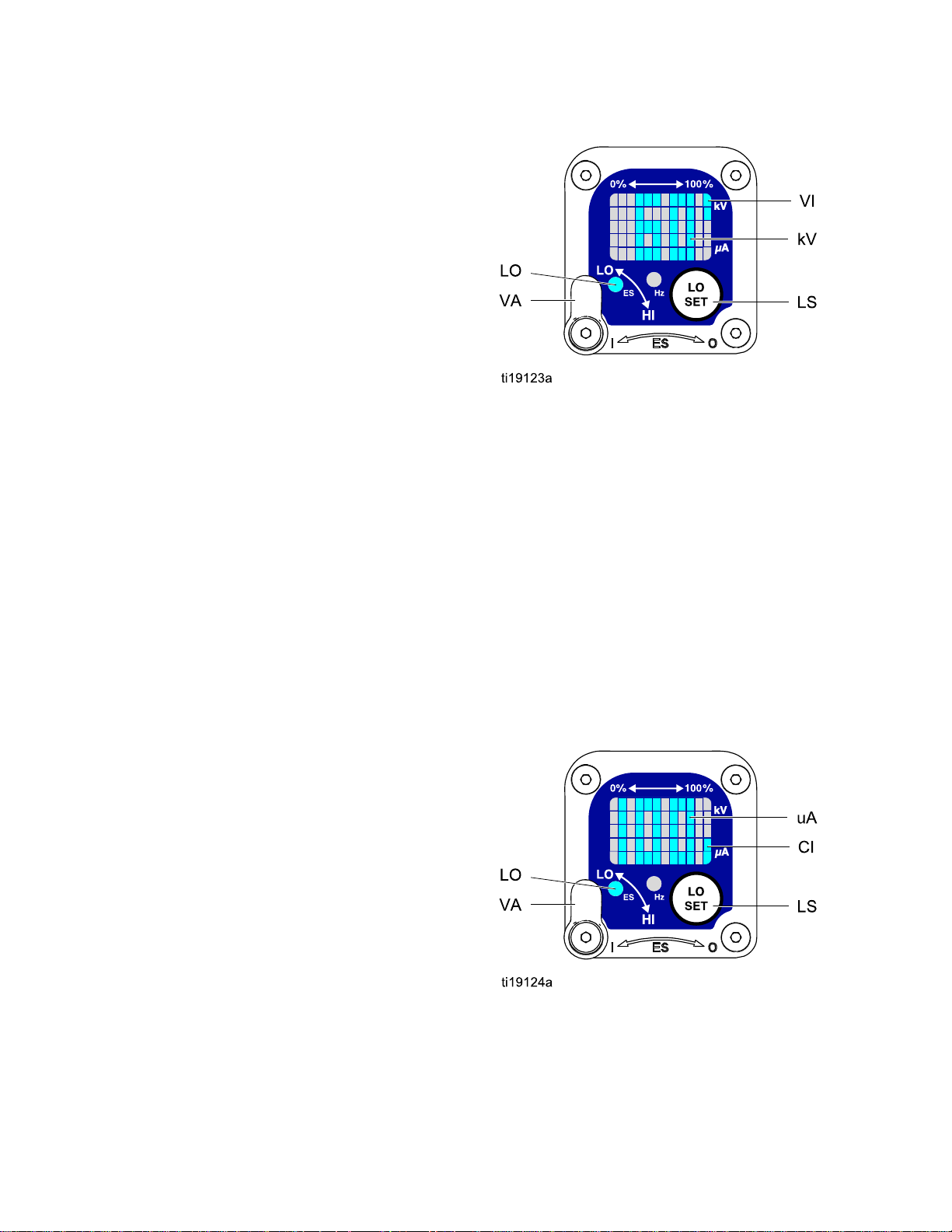
Figure6Voltage(kiloVolts)Screen
Current
Current Current
TheCurrent(microAmperes)Screenisthesecond
screenintheDiagnosticMode.SeeFig.7and
SmartGunKey,page11.Toenterthisscreen,press
theLOSETbuttonwhileintheVoltage(kiloVolts)
Screen.
Thisscreendisplaysthesprayingcurrentofthegun
asanumber(uA),roundedtothenearest5uA.The
twobottomrightLEDs(CI)ofthedisplaypanellight,
indicatingthattheCurrent(microAmperes)Screen
isdisplayed.Thedisplayisareadoutandcannot
bechanged.
PresstheLOSETbuttontoadvancetothe
AlternatorSpeed(Hertz)Screen,page13.Press
andholdforapproximately5secondstoreturnto
OperatingMode.
(microAmperes)
(microAmperes) (microAmperes)
Screen
Screen Screen
Voltage
Voltage Voltage
TheVoltage(kiloVolts)Screenistherstscreento
appearafterenteringDiagnosticMode.SeeFig.6
andSmartGunKey,page11.Toenterthisscreen,
pressandholdtheLOSETbuttonforapproximately
5secondswhileintheOperatingMode.
Thisscreendisplaysthesprayingvoltageofthe
gunasanumber(kV),roundedtothenearest5kV.
ThetwotoprightLEDs(VI)ofthedisplaypanel
light,indicatingthattheVoltage(kiloVolts)Screen
isdisplayed.Thedisplayisareadoutandcannot
bechanged.
PresstheLOSETbuttontoadvancetothe
Current(microAmperes)Screen,page12.Press
andholdforapproximately5secondstoreturnto
OperatingMode.
(kiloVolts)
(kiloVolts) (kiloVolts)
Screen
Screen Screen
12
Figure7Current(microAmperes)Screen
3A2497H
Page 13
GunOverview
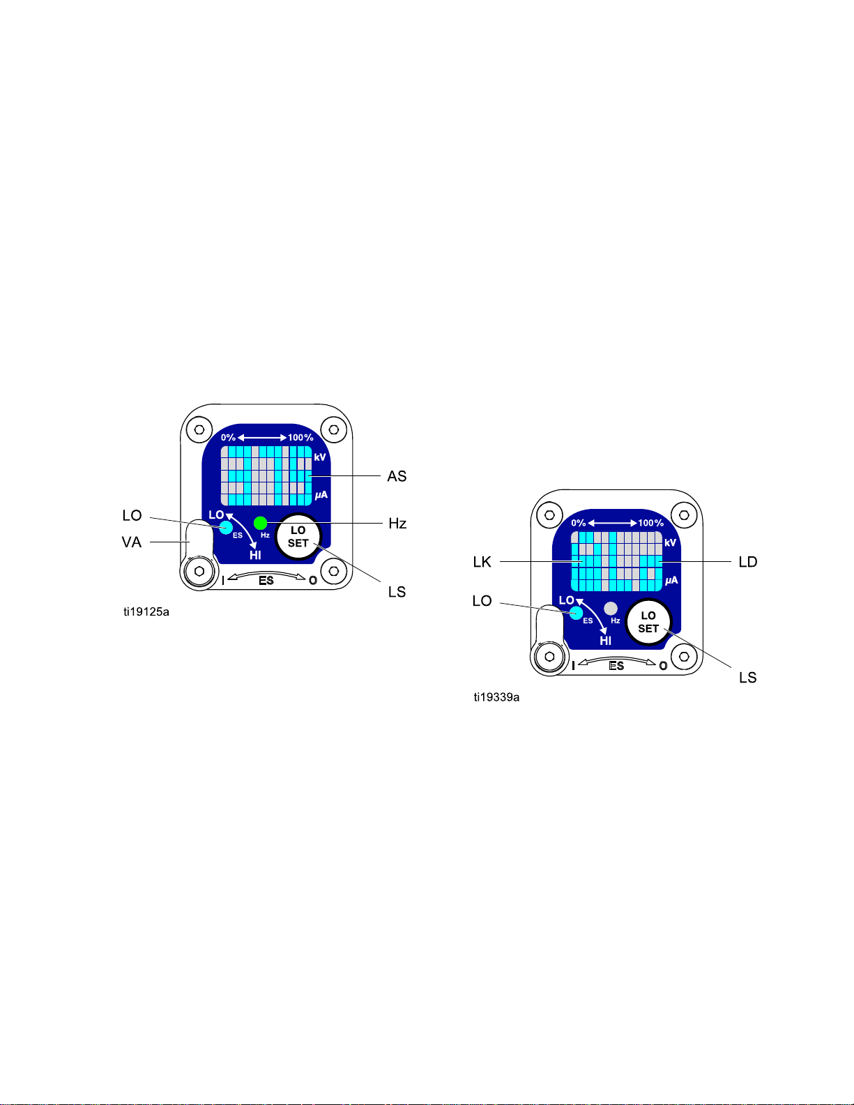
Alternator
Alternator Alternator
TheAlternatorSpeed(Hertz)Screenisthethird
screenintheDiagnosticMode.SeeFig.8and
SmartGunKey,page11.Toenterthisscreen,
presstheLOSETbuttonwhileintheCurrent
(microAmperes)Screen.
Thisscreendisplaysthealternatorspeedasa3
digitnumber(AS),roundedtothenearest5Hz.The
displayisareadoutandcannotbechanged.Ifthe
alternatorspeedisgreaterthan999Hz,thedisplay
willshow999.
TheHzindicatorlightsgreentoshowthatyouare
viewingtheAlternatorSpeed(Hertz)Screen.
PresstheLOSETbuttontoadvancetothe
LowVoltageLockScreen,page13.Pressandhold
forapproximately5secondstoreturntoOperating
Mode.
Speed
Speed Speed
(Hertz)
(Hertz) (Hertz)
Screen
Screen Screen
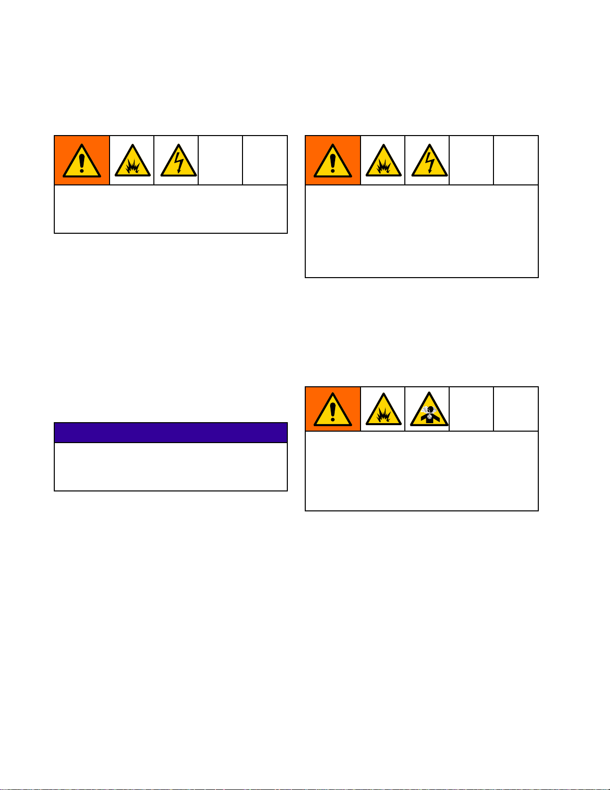
Low
Voltage
Low Low
Voltage Voltage
TheLowVoltageLockScreenisthefourth
screenintheDiagnosticMode.SeeFig.9and
SmartGunKey,page11.Toenterthisscreen,press
theLOSETbuttonwhileintheAlternatorSpeed
(Hertz)Screen.
ThisscreendisplaysthestatusoftheLowVoltage
Lock.Ifthesettingislocked,thelockimage(LK)
appearstotheleftoftheLodisplay(LD).Ifthesetting
isunlocked,thelockimagedoesnotappear.
Tochangethelockstatus,pressandholdthe
LOSETbuttonuntilthelockimageappearsor
disappears.Ifthelockisset,theimagewillalso
appearontheLowVoltageSettingScreenwhenin
lowvoltagemode(seeFig.4).
Note
DiagnosticModecannotbeexitedfromthis
screen,becausepressingandholdingthe
LOSETbuttonisusedtoturnthelockonor
off.Toexit,pressLOSETmomentarilyto
returntotheVoltage(kiloVolts)Screen,then
exitDiagnosticModefromthere.
Lock
Screen
Lock Lock
Screen Screen
Figure8AlternatorSpeed(Hertz)Screen
Figure9LowVoltageLockScreen
3A2497H13
Page 14
Installation
Installation
Installation Installation
System
System System
Theuseofmultiplegunswithoneisolationcabinet
maycauseelectricshock,re,orexplosion.To
helppreventinjuryorequipmentdamage,useonly
onegunperisolationcabinet.
AGracovoltageisolationsystemmusthavethe
followingfeatures:
•Anisolationenclosurethatpreventspersonsfrom
makingcontactwiththehighvoltagecomponents
beforethesystemvoltageisdischarged.All
componentsoftheisolationsystemthatare
chargedtohighvoltagemustbecontainedwithin
theenclosure.
•Ableedresistortodrainoffthesystemvoltage
whenthespraygunisnotinuse.Ametalpartof
theuidsupplyunitmustbeelectricallyconnected
tothebleedresistor.
•Asafetyinterlockthatautomaticallydischargesthe
systemvoltagewhenanyoneopenstheisolation
enclosure.
Requirements
Requirements Requirements
Install
Install Install
Installingandservicingthisequipmentrequires
accesstopartswhichmaycauseelectricshock
orotherseriousinjuryifworkisnotperformed
properly.
•Donotinstallorservicethisequipmentunless
•Complywithalllocalcodesandregulations.
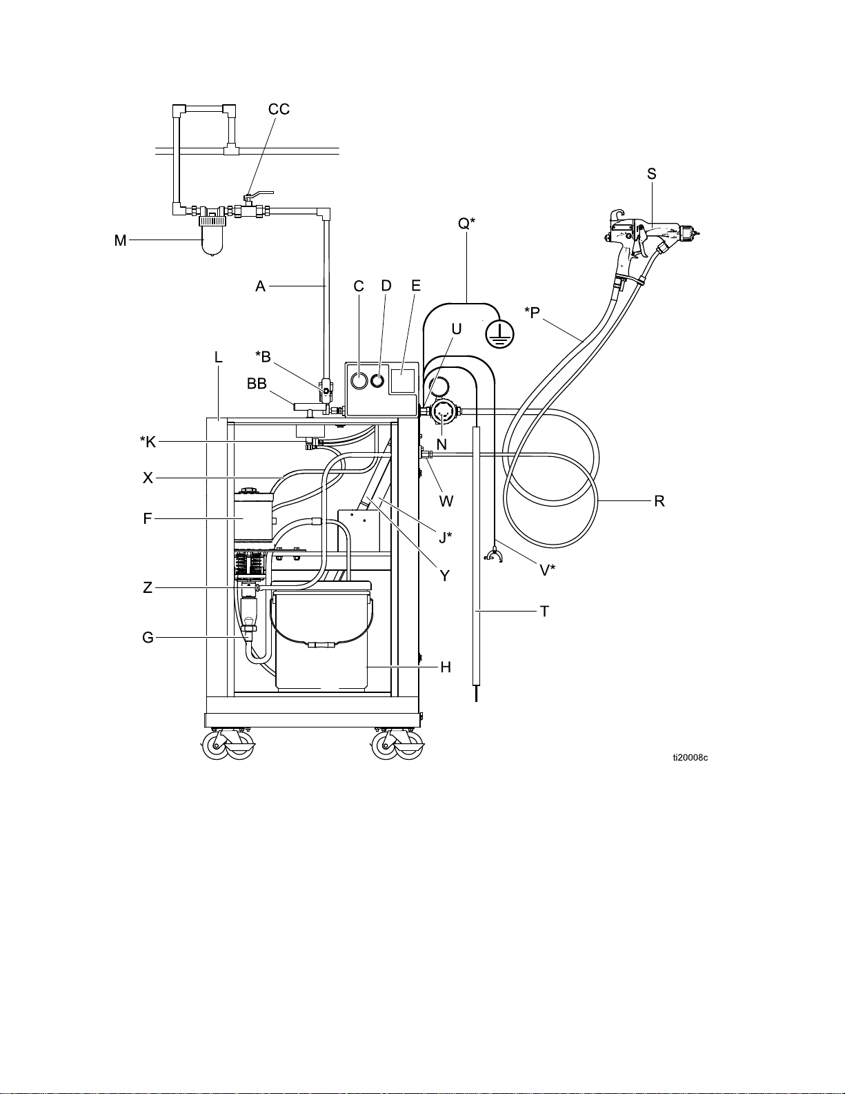
Fig.12(TypicalInstallation)showsatypical
electrostaticair-assistedspraysystem.Itisnotan
actualsystemdesign.Forassistanceindesigning
asystemtosuityourparticularneeds,contactyour
Gracodistributor.
Ventilate
Ventilate Ventilate
the
the the
youaretrainedandqualied.
System
System System
the
Spray
the the
Spray Spray
Booth
Booth Booth
NOTICE
NOTICE NOTICE
Thesystemshouldnothaveanyseverearcing
occurringwhentheisolationmechanismopens
andcloses.Severearcingwillshortenthelifeof
thesystemcomponents.
Note
TheGracowarrantyandapprovalsarevoidif
theelectrostaticspraygunisconnectedtoa
non-Gracovoltageisolationsystemorifthe
gunisoperatedabove60kV.
Warning
Warning Warning
Mountwarningsignsinthesprayareawherethey
caneasilybeseenandreadbyalloperators.An
EnglishWarningSignisprovidedwiththegun.
Sign
Sign Sign
Donotoperatethegununlessventilatingairowis
abovetheminimumrequiredvalue.Providefresh
airventilationtoavoidthebuildupofammableor
toxicvaporswhenspraying,ushing,orcleaning
thegun.Interlockthegunairanduidsupply
topreventoperationunlessventilatingairowis
abovetheminimumrequiredvalue.
Thesprayboothmusthaveaventilationsystem.
Electricallyinterlockthegunairanduidsupplywith
theventilatorstopreventgunoperationanytimethat
theventilationairowfallsbelowminimumvalues.
Checkandfollowalllocalcodesandregulations
regardingairexhaustvelocityrequirements.Verify
theoperationoftheinterlockatleastonceayear.
14
3A2497H
Page 15
Air
Supply
Air Air
Supply Supply
Toreducetheriskofelectricshock,theairsupply
hosemustbeelectricallyconnectedtoatrueearth
ground.Use Use
Hose.
Hose. Hose.
Toreducetheriskofelectricshockorother
seriousinjury,youmustusethered-coloredGraco
ElectricallyConductiveAirHoseforthegunair
supply.Donotusetheblackorgray-coloredGraco
airhoses.
1.SeeFig.12.Installanairlinelter/water
separator(M)onthemainairsupplylineto
ensureadry,cleanairsupplytothegun.Dirtand
moisturecanruintheappearanceofyournished
workpieceandcancausetheguntomalfunction.
2.TheWB3000systemincludesableed-typeair
regulator(N)onthegunairsupplyline(P),to
controlairpressuretothegun.
3.Connectthered-coloredGracoElectrically
ConductiveAirHose(P)betweenthegunair
regulator(N)andthegun’sairinlet.Thegunair
inletttinghasaleft-handthread.Connectthe
airsupplyhosegroundwire(Q)toatrueearth
ground.
Line
Line Line
Use
only
Graco
only only
Graco Graco
Grounded
Grounded Grounded
Air
Supply
Air Air
Supply Supply
Ground
Ground Ground
Connectthemaingroundwire(V)toatrueearth
ground.
the
Cabinet
the the
Cabinet Cabinet
Installation
Trappedaircancausetheuidsupplyunitto
cycleunexpectedly,whichcanresultinserious
injury,includingsplashinguidintheeyesor
ontheskin.Donotoperatetheequipment
withoutthebleed-typeairvalve(B)installed.
4.TheWB3000systemincludesableed-typeair
valve(B).Thebleed-typeairvalveisrequired
toshutoffallairtothesystemandrelieveair
trappedbetweenthevalveandtheuidsupply
unitaftertheairregulatorisshutoff.Connectthe
mainairsupplyline(A)tothebleedvalve.
5.Installanadditionalbleed-typeairvalve(CC)
upstreamoftheairlter(M)toisolatethelter
forservicing.
3A2497H15
Page 16
Installation
Grounding
Grounding Grounding
Theequipmentmustbegroundedtoreducethe
riskofstaticsparkingandelectricshock.Electric
orstaticsparkingcancausefumestoigniteor
explode.Impropergroundingcancauseelectric
shock.Groundallequipment,personnel,objects
beingsprayed,andconductiveobjectsinorclose
tothesprayarea.Theresistancemustnotexceed
100ohms.Groundingprovidesanescapewirefor
theelectriccurrent.
Whenoperatingtheelectrostaticgun,any
ungroundedobjects(suchaspeople,containers,and
tools)inthespraylocationcanbecomeelectrically
charged.
Thefollowingareminimumgroundingrequirements
forabasicelectrostaticwaterbornesystem.Your
systemmayincludeotherequipmentorobjects
whichmustbegrounded.Yoursystemmustbe
connectedtoatrueearthground.Checkground
connectionsdaily.Checkyourlocalelectricalcodes
andregulationsfordetailedgroundinginstructions.
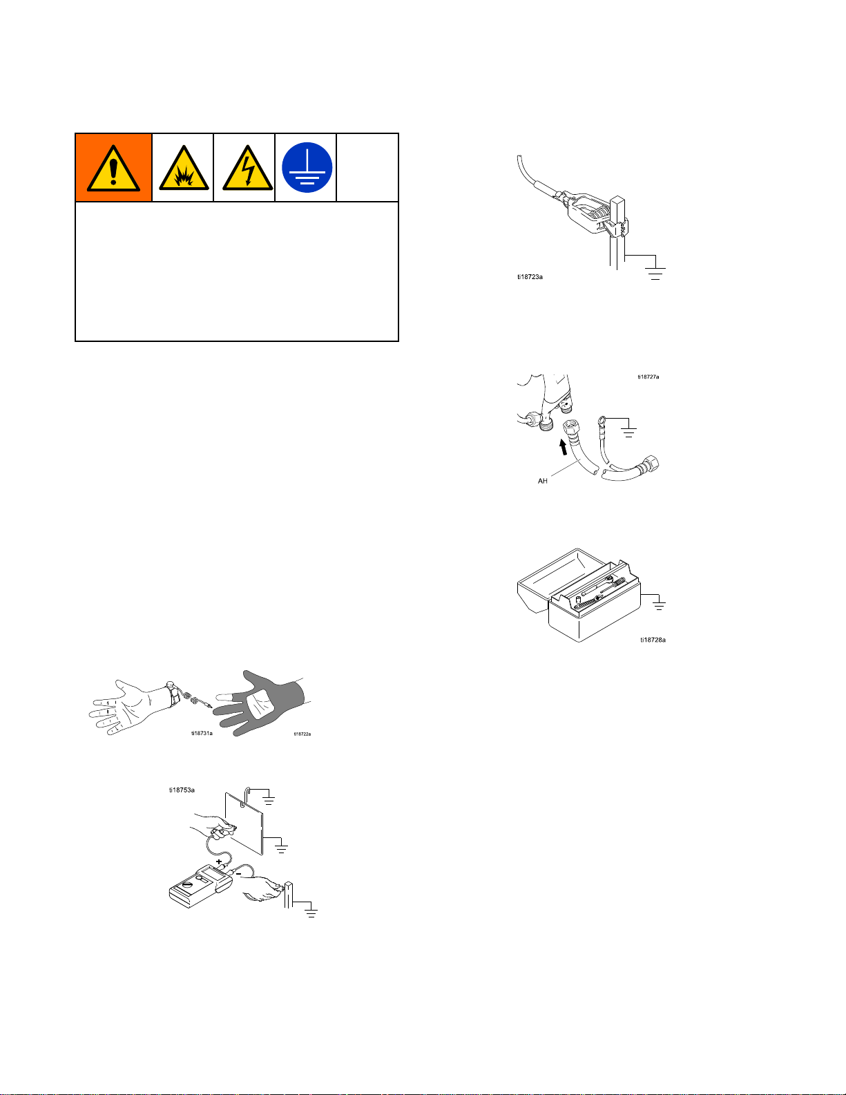
Allpersonsenteringthesprayarea:
•
shoeshavingconductivesolessuchasleather,
orwearpersonalgroundingstraps.Donot
wearshoeswithnon-conductivesolessuchas
rubberorplastic.Ifglovesarenecessary,wear
theconductiveglovessuppliedwiththegun.If
non-Gracoglovesareworn,cutoffngersorpalm
areaofglovestoensureyourhandcontactsthe
groundedgunhandle.
•
Objectbeingsprayed:
cleanandgroundedatalltimes.
Keeptheworkpiecehangers
mustwear
•
VoltageIsolationSystem:
voltageisolationsystemtoatrueearthground.
SeeGroundtheCabinet,page15.
•
ElectrostaticAir-AssistedSprayGun:
thegunbyconnectingthered-coloredGraco
GroundedAirHosetothegun,andconnectingthe
airhosegroundwiretoatrueearthground.See
CheckGunElectricalGrounding,page26.
•
Allelectricallyconductiveobjectsordevicesinthe
sprayarea:
•
Fluidandwastecontainers:
wastecontainersinthesprayarea.Donotusepail
linersunlesstheyareconductiveandgrounded.
Whenushingthespraygun,thecontainerused
tocatchtheexcessuidmustbeelectrically
conductiveandgrounded.
Aircompressors:
•
tothemanufacturer'srecommendations.
•
Allairlines
groundedhoseswithamaximumof100feet(30.5
m)combinedhoselengthtoensuregrounding
continuity.
mustbeproperlygrounded.
Groundtheequipmentaccording
mustbeproperlygrounded.Useonly
Electricallyconnectthe
Groundalluidand
Ground
163A2497H
Page 17
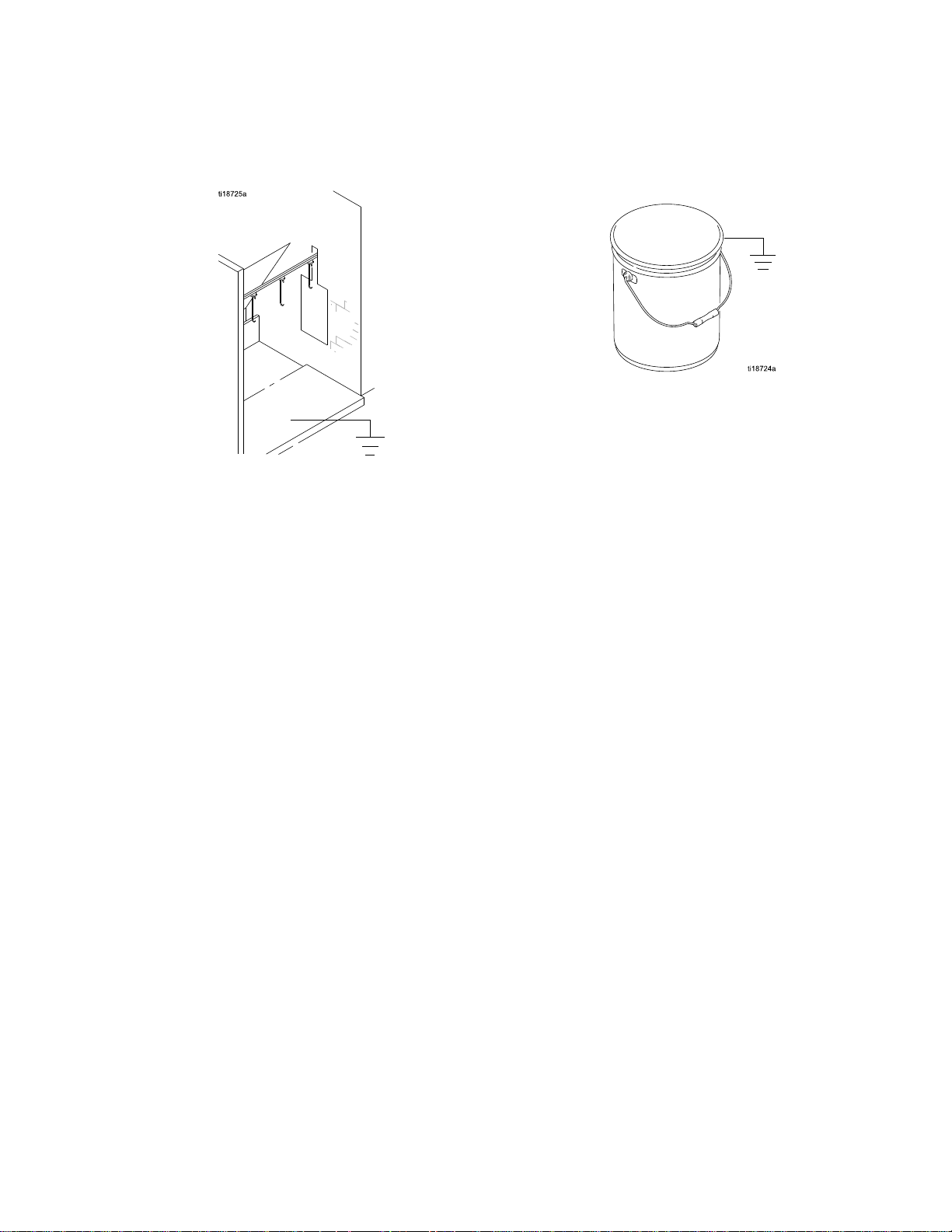
•
Theoorofthesprayarea:
conductiveandgrounded.Donotcovertheoor
withcardboardoranynon-conductivematerial
whichwouldinterruptgroundingcontinuity.
mustbeelectrically
•
Allsolventpails:
metalcontainers,whichareconductive.Donot
useplasticcontainers.Onlyusenon-ammable
solvents.Donotstoremorethanthequantity
neededforoneshift.
Useonlyapproved,grounded
Installation
3A2497H
17
Page 18
Installation
Connect
Connect Connect
AlwaysuseaGracowaterborneuidhosebetween
thevoltageisolationsystemuidoutletandthegun
uidinlet.
Beforeconnectingthewaterborneuidhosetothe
gun,blowitoutwithairandushwithwaterto
removecontaminants.Flushthegunbeforeusingit.
Toreducetheriskofelectricshock,installonly
onecontinuousGracowaterbornehosebetween
theisolateduidsupplyandthegun.Donotsplice
hosestogether.
1.Removethegunairinlettting(21).
the
Waterborne
the the
Waterborne Waterborne
Fluid
Fluid Fluid
Hose
Hose Hose
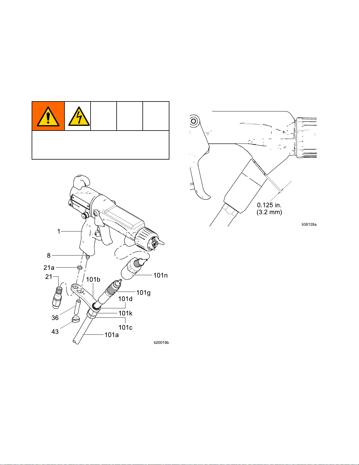
3.Makesurethebarreluidinletiscleananddry.
Applydielectricgreasetothethreadsandfrontof
thebarrelconnector(101a)andscrewitintothe
uidinletjustuntilsnug.Thencontinuetotighten
thettingaminimumof1/2turnandcontinueto
rotateuntilthettingisorientedasshown.The
gapbetweenthettingandthebarrelmustbe
lessthan.125in(3.2mm).
Figure10ConnecttheFluidHose
2.Removetheo-ring(21a)andassembletheinlet
ttingthroughthebracket.Reassemblethe
o-ring.
Figure11OrientationofFittingandBarrel
4.Loosenthestrainreliefnut(101c).
5.Applydielectricgreasetothethreadsofthe
hoseconnector(101g).Pulltheconnectorback
andapplygreasetotheoutsidediameterofthe
hose.Threaditintothebarrelconnector(101n)
untilsnugandthenaminimumof1/2turnmore.
Useawrenchtoholdthebarrelconnectorwhen
tightening.
6.Alignthebracket(101b)holeswiththeairinlet
andexhaustoutlet.Securewiththeairinlettting
(21).
7.Tightenthestrainreliefnut(101c).
8.Presstheexhausttube(36)ontotheexhaust
valve.Securewiththeclamp(43).
Note
Wheneverpossible,keeptheuidhose
assembledtothegunbarrel.Toremove
thebarrel,disconnectthehosebracket
atthegunhandle.
9.Loosenthestrainreliefnutatthehoseinletend.
10.Slidetheotherendofthehosethroughthehole
inthesideoftheisolatedenclosure.Connectthe
swivel(Z)totheuidoutletofthepump.
183A2497H
Page 19
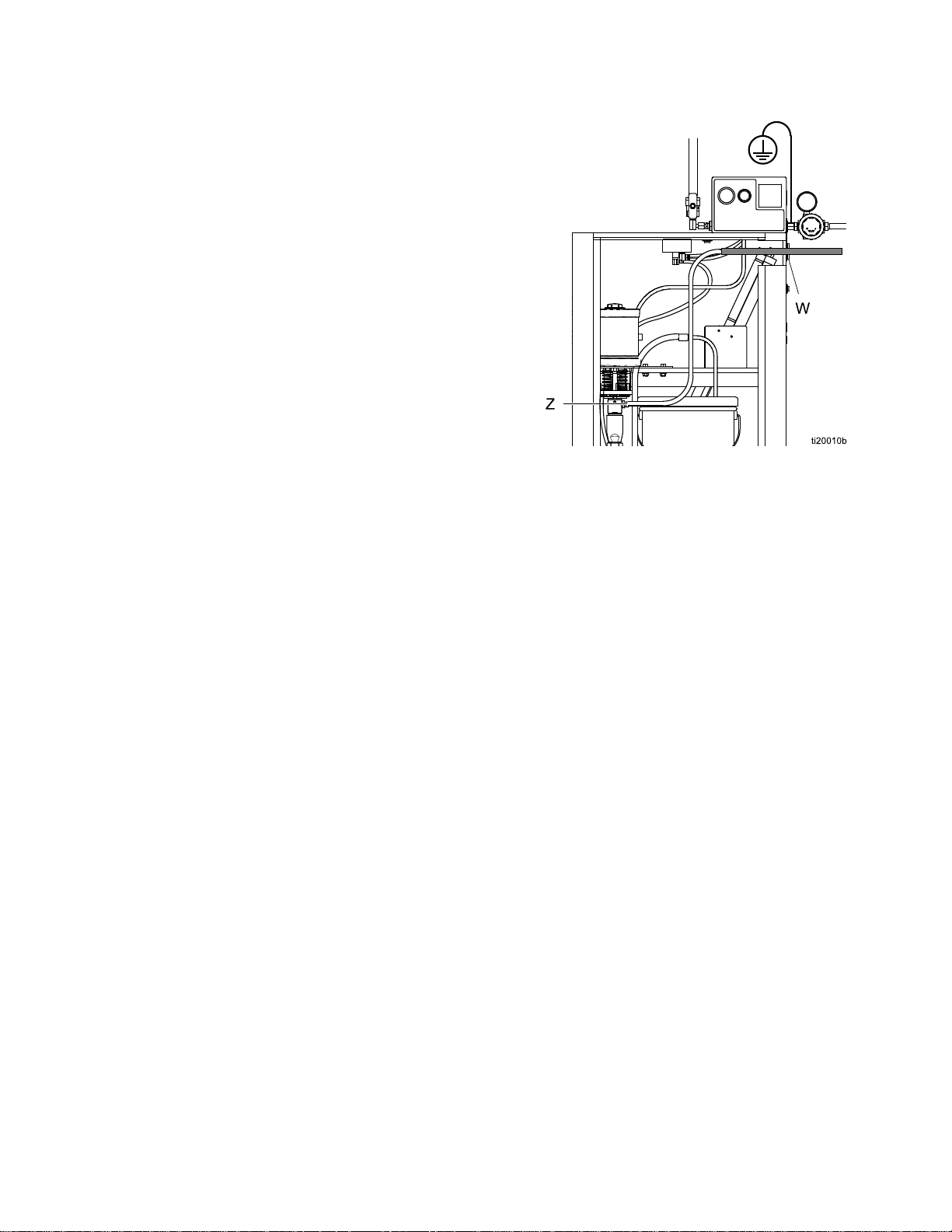
11.Securethehosetothesideoftheenclosurewith
thebracket(W).Aboltassemblesthroughthe
holeinthebracketandscrewsintothesideof
theenclosure.
12.Tightenthestrainreliefnut.
Note
TheGracowarrantyandapprovals
arevoidiftheelectrostaticspraygun
isconnectedtoanon-Gracovoltage
isolationsystemorifthegunisoperated
above60kV.
Installation
Figure12HoseConnectionatWB3000Enclosure
3A2497H19
Page 20
Installation
Figure13TypicalInstallation,ProXpWaterborne
System
203A2497H
Page 21

Installation
Typical
Typical Typical
Item
Item Item
A
B*Bleed-TypeAirShutoffValve
CPumpAirPressureGauge
DPumpAirPressureRegulator
EkVMeter
FPump
GPumpSuctionHose
H
J*
K*EnclosureSafetyInterlock
LIsolatedEnclosure
M
N
P*GracoRedGroundedAirHose(left-hand
Q*GunAirHoseGroundWire
Installation
Installation Installation
Description
Description Description
MainAirSupplyLine
PaintContainer
BleedResistor
GunAirLineFilter
GunAirPressureRegulator
threads)
Key
Key Key
Item
Item Item
S
T
U
V*MainGroundWire
W
X
Y
Z
AA
BB
CCAccessoryBleed-TypeAirShutoffValve
*Theseitemsarerequiredforsafeoperation.They
areincludedwiththeWB3000system.
Description
Description Description
WaterborneElectrostaticAir-Assisted
SprayGun
GroundingRod
GroundTerminal
StrainReliefFitting
PumpAirSupplyLine
GroundingCylinder
PumpFluidOutletFitting
IsolatedEnclosureDoor(notshown,to
illustrateinternalcomponents.Doormust
beclosedandlockedtooperatesystem).
EnclosureT-HandleLockingScrew(part
ofdoorassembly)
R
GracoWaterborneFluidHose
3A2497H
21
Page 22
Installation
Agitator
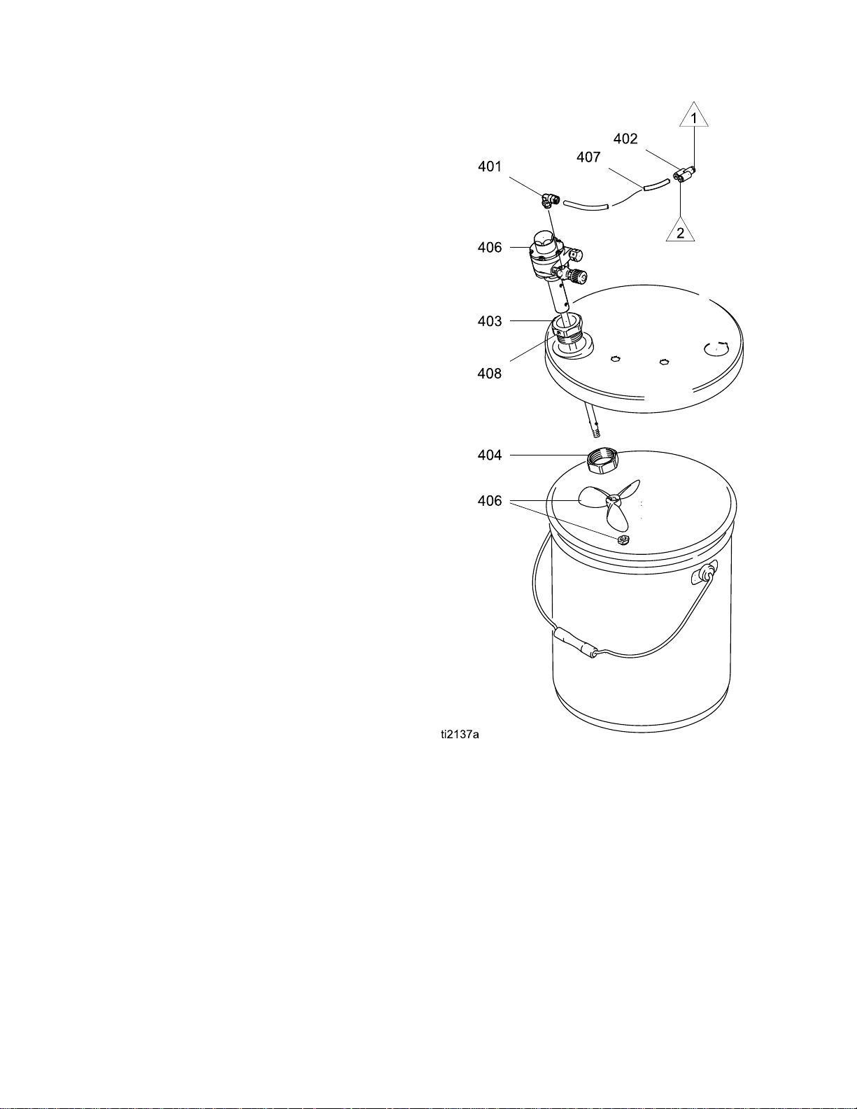
Agitator Agitator
ToaddanagitatortotheGracoisolationsystem,order
PartNo.245895.See245895AgitatorKit,page72,
forthekitpartslist.
1.Dischargethesystemvoltage(seeFluidVoltage
DischargeandGroundingProcedure,page29).
2.Relievethepressure(see
PressureReliefProcedure,page28).
3.Opentheisolatedenclosuredoor.
4.Removethebackofthecontrolbox(258).
5.Removetube(A2)fromelbow(282)attheair
manifold;seeTubingandWiring,page62.
InstalltheYtting(402)intotheelbow.Install
tubes(A2)and(407)intotheYtting.Routethe
agitatortube(407)intothecabinet.
6.Replacethebackofthecontrolbox(258).
7.Assembletheotherpartsofthekitasshown.
Securetheagitatorwiththesetscrew(408).
8.Returnthesystemtoservice.
Kit
Accessory
Kit Kit
Accessory Accessory
Figure14245895AgitatorKit
22
3A2497H
Page 23
GunSetup
Gun
Gun Gun
Gun
Gun Gun
Toreducetheriskofreandexplosion,uidsused
mustmeetthefollowingammabilityrequirements:
•FM, FM,
•CE CE
Setup
Setup Setup
Setup
Setup Setup
FM,
FMc
FMc FMc
Materialdoesnotsustainburninginaccordance
withtheStandardTestMethodforSustained
BurningofLiquidMixtures,ASTMD4206.
CE
EN
- --EN EN
Materialisclassiedasnon-ignitableasdened
byEN50059:2018.
Formoreinformation,see
IgnitabilityofCoatingMaterials,page73.
Procedure
Procedure Procedure
Approved:
Approved: Approved:
50059
50059 50059
Compliant:
Compliant: Compliant:
Toreducetheriskofaninjury,followthe
PressureReliefProcedure,page28wheneveryou
areinstructedtorelievethepressure.
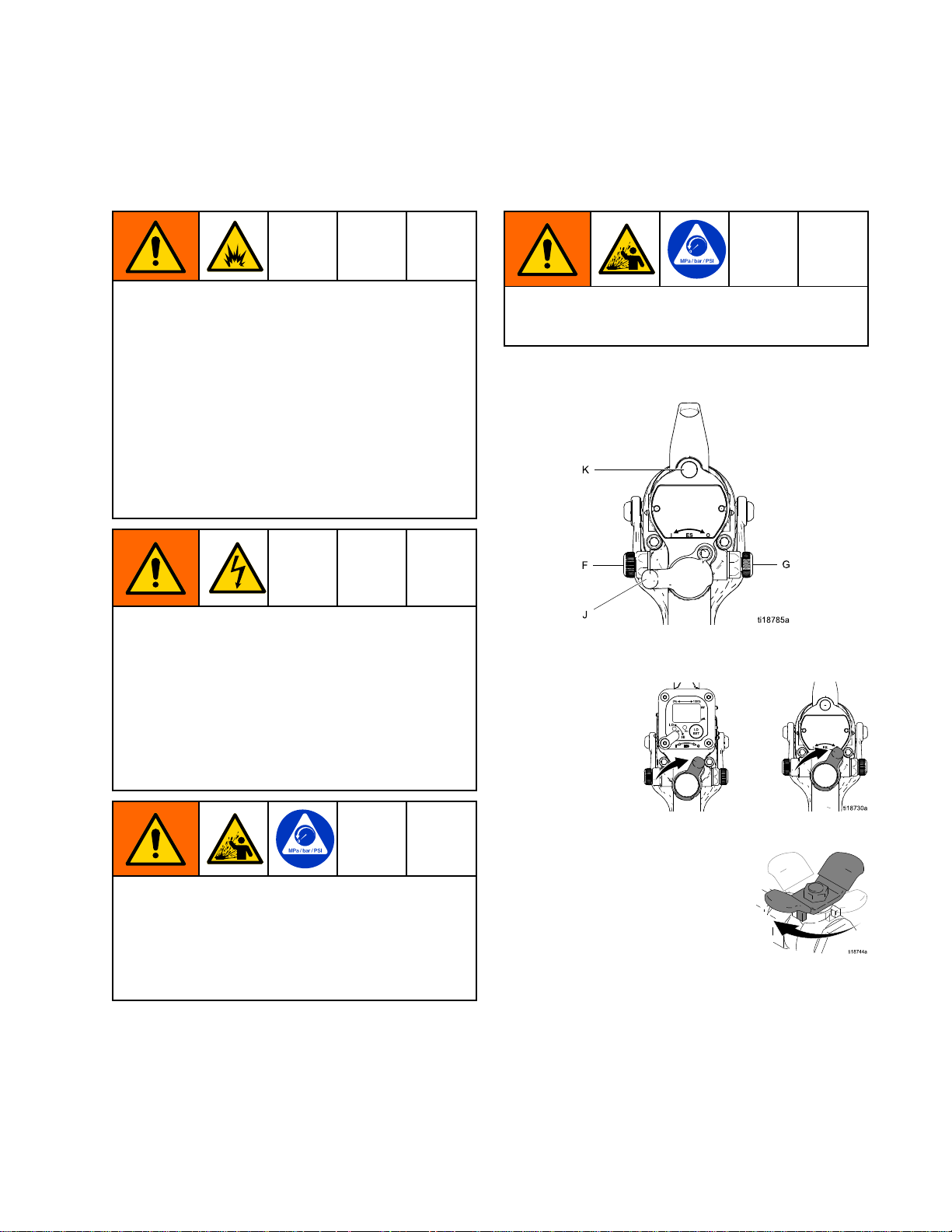
Seethegurebelowtolocatetheelectrostaticgun
controls.
Contactwiththechargedcomponentsofthespray
gunwillcauseanelectricshock.Donottouch
thegunnozzleorelectrodeorcomewithin4in.
(102mm)oftheelectrodeduringoperationor
untilperformingtheFluidVoltageDischargeand
GroundingProcedure,page29.
FollowtheFluidVoltageDischargeandGrounding
Procedure,page29whenyoustopsprayingand
wheneveryouareinstructedtodischargethe
voltage.
Toreducetheriskofcomponentrupture,which
cancauseseriousinjury,donotexceedthe
maximumworkingpressureofthelowestrated
systemcomponent.Thisequipmenthasa100psi
(0.7MPa,7bar)maximumairworkingpressure
anda3000psi(21MPa,210bar)maximumuid
workingpressure.
Figure15ElectrostaticGunControls
1.TurnOFF(O)theESOn-Offswitch(J).
2.Shutofftheairbleedvalvetothegun.
3A2497H23
Page 24

GunSetup
3.Checkgunresistance.See
TestGunResistance,page36.
4.FollowallstepsunderGrounding,page16.
5.Followallstepsunder
CheckGunElectricalGrounding,page26.
Readingmustbelessthan100ohms.
6.Connecttheexhausttubeandsecurewiththe
clampprovided.
7.Flushifneeded.SeeFlushing,page31.
Toreducetheriskofaskininjectioninjury,alwaysfollowthe
PressureReliefProcedure,page28,
beforeremovingorinstallingthespraytip,air
cap,ortipguard.
11.Closetheatomizingairadjustmentvalve(G)and
thefanairadjustmentvalve(F).
12.CheckthattheESOn-OffswitchisOFF(O).
13.Startthepump.Settheuidregulatorto400psi
(2.8MPa,28bar).
14.Sprayatestpattern.Examinetheparticlesizein
thecenterofthepattern(tailswillberemoved
instep18).Increasethepressureinsmall
increments.Sprayanotherpattern.Compare
particlesize.Continueincreasingpressureuntil
theparticlesizeremainsconstant.Donotexceed
3000psi(21MPa,210bar).
8.Theuidoutputandpatternwidthdepend
onthesizeofthespraytip,theuid
viscosity,andtheuidpressure.Usethe
SprayTipSelectionChart,page68,asaguide
forselectingtheappropriatespraytipforyour
application.
9.Alignthespraytiptabwiththegrooveintheair
cap.Installthetip.
10.Installtheaircapandretainingring.Orientate
theaircapandtightentheretainingringsecurely.
15.TurnON(I)theESOn-Offswitch.
24
3A2497H
Page 25

GunSetup
16.CheckthattheESindicator(Hzindicatoron
Smartguns)islit,orcheckthatthekVindicator
ontheisolatedenclosurereads30–50kV.
TheactualsprayingvoltageforAAwaterborne
systemsis40–50kV,butbecausethecharging
electrodedoesnotdirectlycontacttheuid,the
voltagemeasuredbytheWB3000kVmeterwill
be5–10kVlower.Seethefollowingtable.
Table
Table Table
Indicator
Indicator Indicator
Amber
LED
2 22. ..LED LED
Color
Color Color
Green
Red
Indicator
Indicator Indicator
Whenspraying,theindicator
shouldremaingreen,indicating
sufcientairpressuretothe
alternatorturbine.
Iftheindicatorturnsamberafter
1second,theairpressureistoo
low.Increaseairpressureuntil
theindicatorisgreen.
Iftheindicatorturnsredafter1
second,theairpressureistoo
high.Decreaseairpressureuntil
theindicatorisgreen.
Colors
Colors Colors
Description
Description Description
18.Turntheatomizingairadjustmentvalve
counterclockwiseuntilanytailsdisappear.
19.Ifdesiredatomizationisnotachieved,change
thetipsize.Thesmallerthetiporice,thener
theatomization.
20.Sprayatestpiece.Examinetheedges
forcoverage.Ifwrapispoor,see
Troubleshooting,page39.
17.Setthegunairregulatortodeliveraminimumof
45psi(0.32MPa,3.2bar)atgunwhentriggered,
toensurefullsprayingvoltage.Seethetable
below.
Table
Table Table
mm]
mm] mm]
Pressure
3 33. ..Pressure Pressure
Air
Hose
Air Air
Hose Hose
Length
Length Length
(using
(using (using
in ininft ftft(m) (m)
5/16
5/16 5/16
diameter
diameter diameter
15(4.6)52(0.36,3.6)
25(7.6)57(0.40,4.0)
50(15.3)68(0.47,4.7)
75(22.9)80(0.56,5.6)
100(30.5)90(0.63,6.3)
Drop
Drop Drop
Air
Air Air
(m)
in.
[8
in. in.
[8 [8
hose)
hose) hose)
Regulator
Regulator Regulator
psi
in ininpsi psi
[with
gun
[with [with
gun gun
Setting
Setting Setting
(MPa,
(MPa, (MPa,
bar)
bar) bar)
triggered]
triggered] triggered]
Note
Ifanarrowerpatternisneededoccasionally,
openthefanairadjustmentvalveslightly.
(Excessivefanairowcancausepaint
buildupontheaircap.)
3A2497H25
Page 26

GunSetup
Check
Check Check
MegohmmeterPartNo.241079(AA-seeFig.
14)isnotapprovedforuseinahazardousarea.
Toreducetheriskofsparking,donotusethe
megohmmetertocheckelectricalgrounding
unless:
•Thegunhasbeenremovedfromthehazardous
•Orallsprayingdevicesinthehazardousarea
Failuretofollowthiswarningcouldcausere,
explosion,andelectricshockandresultinserious
injuryandpropertydamage.
GracoPartNo.241079Megohmmeterisavailable
asanaccessorytocheckthatthegunisproperly
grounded.
1.Haveaqualiedelectricianchecktheelectrical
2.TurnOFF(O)theESOn-Offswitch.
Gun
Gun Gun
area;
areturnedoff,ventilationfansinthehazardous
areaareoperating,andtherearenoammable
vaporsinthearea(suchasopensolvent
containersorfumesfromspraying).
groundingcontinuityofthespraygunandair
hose.
Electrical
Electrical Electrical
Grounding
Grounding Grounding
6.Measuretheresistancebetweenthegunhandle
(BB)andatrueearthground(CC).Usean
appliedvoltageof500minimumto1000volts
maximum.Theresistanceshouldnotexceed
100ohms.SeeFig.14.
Figure16CheckGunElectricalGrounding
7.Iftheresistanceisgreaterthan100ohms,check
thetightnessofthegroundconnectionsandbe
suretheairhosegroundwireisconnectedtoa
trueearthground.Iftheresistanceisstilltoo
high,replacetheairhose.
8.Usinganohmmeter(AA)measuretheresistance
betweenthecabinetgroundlug(214)andatrue
earthground(CC).Theresistancemustbeless
than100ohms.
3.Turnofftheairanduidsupplytothegun.Follow
thePressureReliefProcedure,page28.
4.Disconnecttheuidhose.
5.Makesurethegroundedairhoseisconnected
andthehosegroundwireisconnectedtoatrue
earthground.
Figure17CheckCabinetGrounding
263A2497H
Page 27

GunSetup
Flush
Flush Flush
Theequipmentwastestedinuidatthefactory.To
avoidcontaminatingyouruid,ushtheequipment
withacompatiblesolventbeforeusingtheequipment.
SeeFlushing,page31.
Before
Before Before
Using
Using Using
Equipment
Equipment Equipment
3A2497H
27
Page 28

Operation
Operation
Operation Operation
Pressure
Pressure Pressure
Thisequipmentstayspressurizeduntilpressure
ismanuallyrelieved.Tohelppreventserious
injuryfrompressurizeduid,suchasskininjection,
splashinguidandmovingparts,followthe
PressureReliefProcedurewhenyoustopspraying
andbeforecleaning,checking,orservicingthe
equipment.
1.TurnOFF(O)theESOn/Offswitch.
2.FollowtheFluidVoltageDischargeand
GroundingProcedure,page29.
3.Engagethetriggerlock.
Relief
Relief Relief
Procedure
Procedure Procedure
5.Disengagethetriggerlock.
6.Triggerthegunintoagroundedmetalwaste
containertorelievetheuidpressure.
7.Engagethetriggerlock.
8.Openthepumpdrainvalve,havingawaste
containerreadytocatchthedrainage.Leave
thepumpdrainvalveopenuntilyouareready
tosprayagain.
4.Turnofftheairbleedvalvestotheuidsource
andtothegun.
9.Ifthespraytiporhoseiscompletelycloggedor
pressureisnotfullyrelieved,slowlyloosenthe
hoseendcoupling.Nowclearthespraytipor
hose.
283A2497H
Page 29

Operation
Operating
Operating Operating
Checkthefollowinglistdaily,beforestartingthe
system.
Alloperatorsareproperlytrainedtooperate
anelectrostaticwaterborneair-assistedspray
systemasinstructedinthismanual.
Alloperatorsaretrainedinthe
PressureReliefProcedure,page28.
Theelectrostaticsareturnedoffandsystem
voltageisdischargedaccordingtothe
FluidVoltageDischargeandGrounding
Procedure,page29,beforeanypersonen-
terstheisolationenclosure,beforecleaning,
andbeforeperforminganymaintenanceor
repair.
Thesystemisgroundedaccordingtothe
instructionsinGrounding,page16.
TheGracowaterborneuidhoseisingood
conditionwithnocutsorabrasionsofthe
innerlayer.Replacehoseifdamaged.
Ventilationfansareoperatingproperly.
Alldebris,includingammableuidsand
rags,isremovedfromthesprayarea.
Fluidsusedmustmeetthefollowing
ammabilityrequirements:
Checklist
Checklist Checklist
Fluid
Fluid Fluid
Grounding
Grounding Grounding
Theuidsupplyischargedwithhighvoltageuntil
thevoltageisdischarged.Contactwiththecharged
componentsofthevoltageisolationsystemor
spraygunelectrodewillcauseanelectricshock.
Toavoidanelectricshock,followtheFluid Fluid
Discharge
Discharge Discharge
•wheneveryouareinstructedtodischargethe
•beforecleaning,ushing,orservicingthesystem
•beforeapproachingthefrontofthegun
•orbeforeopeningtheisolationenclosureforthe
1.TurntheESON/OFFvalveOFFandwait30
Voltage
Voltage Voltage
and
and and
voltage
equipment
isolateduidsupply.
seconds,toallowthevoltagetodischarge
throughthebleedresistor.
Discharge
Discharge Discharge
Procedure
Procedure Procedure
Grounding
Grounding Grounding
and
and and
Fluid
Procedure:
Procedure: Procedure:
Voltage
Voltage Voltage
FM,
FMc
•FM, FM,
Materialdoesnotsustainburningin
accordancewiththeStandardTestMethod
forSustainedBurningofLiquidMixtures,
ASTMD4206.
CE
•CE CE
Materialisclassiedasnon-ignitableas
denedbyEN50059:2018.
Formoreinformation,see
IgnitabilityofCoatingMaterials,page73.
Approved:
FMc FMc
Approved: Approved:
EN
50059
- --EN EN
50059 50059
Compliant:
Compliant: Compliant:
2.FullyunscrewthedoorT-handlelockingscrew.
Thiswillshutofftheairtothegunandtriggerthe
groundingcylindertodischargeanyremaining
electricalcharge.
3.Usethegroundingrodtotouchthepump
andsupplypail.Ifyouseeanyarcs,see
ElectricalTroubleshooting,page43.
3A2497H29
Page 30

Operation
Fill
the
Fill Fill
1.FollowtheFluidVoltageDischargeand
2.FollowthePressureReliefProcedure,page28.
3.Opentheisolatedenclosuredoor.
4.Removethepailcoverfromthepail,holdingarag
5.Removethesupplypailfromtheenclosure.
6.Cleanupanyuidspillsintheenclosure,using
7.Fillthesupplypailwithuidandreturnittothe
8.Reinstallthepailcover,holdingaragoverthe
9.Closetheisolatedenclosuredoorandfasten
Startup
Startup Startup
FollowallstepsunderGunSetupProcedure,page23.
Fluid
the the
Fluid Fluid
GroundingProcedure,page29.
overthesuctiontubestrainertopreventanyuid
fromdrippingintotheisolatedenclosure.Place
thecoverandsuctiontubeoutsidetheenclosure.
Besuretowipeupalluidspillsintheisolated
enclosure.Fluidcancreateaconductivepath
andcausethesystemtoshortout.
asoftclothandanon-ammable,compatible
solvent.
enclosure.Cleanupanyspills.
suctiontubestrainertopreventuidspillswhile
youplacethepumpsuctiontubeinthepail.
securelywiththeT-handlelockingscrew.
Supply
Supply Supply
NOTICE
NOTICE NOTICE
•Theconditionofthegun’selectrical
componentshasbeencheckedasinstructedin
ElectricalTests,page36.
•Ventilationfansareoperatingproperly.
•Workpiecehangersarecleanandgrounded.
•Alldebris(includingammableuidsandrags)is
removedfromthesprayarea.
•Allammableuidsinthespraybootharein
approved,groundedcontainers.
•Allconductiveobjectsinthesprayareaare
electricallygroundedandtheoorofthespray
areaiselectricallyconductiveandgrounded.
Shutdown
Shutdown Shutdown
Toreducetheriskofaninjury,followthe
PressureReliefProcedure,page28wheneveryou
areinstructedtorelievethepressure.
1.Dischargethesystemvoltage.SeeFluidVoltage
DischargeandGroundingProcedure,page29.
2.Flushthegun.SeeFlushing,page31.
3.FollowthePressureReliefProcedure,page28.
4.Hangthegunfromitshook,withthenozzle
pointingdown.Besuretokeepthegunfrom
groundingout.
Checkthefollowinglistdaily,beforestartingto
operatethesystem,tohelpensureyouofsafe,
efcientoperation.
•Alloperatorsareproperlytrainedtosafelyoperate
anautomaticelectrostaticairspraysystemas
instructedinthismanual.
•Alloperatorsaretrainedinthe
PressureReliefProcedure,page28.
•Thewarningsignprovidedwiththegunismounted
inthesprayareawhereitcanbeeasilyseenand
readbyalloperators.
•Thesystemisthoroughlygroundedandthe
operatorandallpersonsenteringthesprayarea
areproperlygrounded.SeeGrounding,page16.
303A2497H
Page 31

Maintenance
Maintenance
Maintenance Maintenance
Daily
Daily Daily
Checkthefollowinglistdailyuponcompletionof
equipmentusage.
Care
Care Care
Flushthegun.SeeFlushing,page31.
Cleantheuidandairlinelters.
Cleantheoutsideofthegun.See
CleantheGunDaily,page33.
Cleantheaircapandspraytipdaily,at
aminimum.Someapplicationsrequire
morefrequentcleaning.Replacethespray
tipandaircapiftheyaredamaged.See
CleantheGunDaily,page33.
Checktheelectrodeandreplace
ifbrokenordamaged.See
ElectrodeReplacement,page45.
Checkforuidleakagefromthegunanduid
hoses.Tightenttingsorreplaceequipment
asneeded.
Checkelectricalgrounding.See
CheckGunElectricalGrounding,page26.
and
Cleaning
and and
Cleaning Cleaning
Checklist
Checklist Checklist
Flushing
Flushing Flushing
•Flushbeforechanginguids,beforeuidcandry
intheequipment,attheendoftheday,before
storing,andbeforerepairingequipment.
•Flushatthelowestpressurepossible.Check
connectorsforleaksandtightenasnecessary.
•Flushwithanon-ammablesolventthatis
compatiblewiththeuidbeingdispensedandthe
equipmentwettedparts.
Toreducetheriskofre,explosion,orelectric
shock,turnOFF(O)theESOn-Offswitchbefore
ushingthegun.
FollowtheFluidVoltageDischargeandGrounding
Procedure,page29,beforeushing.
Onlyush,purge,orcleanthegunwithuidsthat
meetthefollowingammabilityrequirements:
FM,
FMc
•FM, FM,
Materialdoesnotsustainburninginaccordance
withtheStandardTestMethodforSustained
BurningofLiquidMixtures,ASTMD4206.
CE
•CE CE
Materialisclassiedasnon-ignitableasdened
byEN50059:2018.
Formoreinformation,see
IgnitabilityofCoatingMaterials,page73.
Approved:
FMc FMc
Approved: Approved:
EN
50059
- --EN EN
50059 50059
Compliant:
Compliant: Compliant:
NOTICE
NOTICE NOTICE
Onlyusenon-ammablesolventswhenushing
orcleaningequipment.
1.TurnOFF(O)theESOn-Offswitch.Wait30
secondsforthevoltagetobleedoff.
2.Dischargethesystemvoltage.SeeFluidVoltage
DischargeandGroundingProcedure,page29.
3.FollowthePressureReliefProcedure,page28.
3A2497H31
Page 32

Maintenance
4.Removeandcleantheaircapandspraytip.
5.Changetheuidsourcetonon-ammable
solvent.
6.Pointthegunintoagroundedmetalpail.Flush
untilcleansolventowsfromthegun.
7.FollowthePressureReliefProcedure,page28.
Engagethetriggerlock.
8.Alignthespraytiptabwiththegrooveintheair
cap.Installthetip.
9.Reinstalltheaircap,tipguard,andretainingring.
10.Opentheisolatedenclosuredoor.Leavethe
ushinguidinthesystemuntilyouareready
tosprayagain.
11.Hangthegunfromitshook,withthenozzle
pointingdown.Besuretokeepthegunfrom
groundingout.
12.Beforeusingthesystemelectrostaticallyagain,
makesurenoammablevaporsarepresent.
323A2497H
Page 33

Maintenance
Clean
Clean Clean
1.TurnOFF(O)theESOn-Offswitch.
2.Dischargethesystemvoltage.SeeFluidVoltage
3.FollowthePressureReliefProcedure,page28.
4.Removetheaircap/tipguardandspraytip.
the
Gun
the the
Gun Gun
DischargeandGroundingProcedure,page29.
Daily
Daily Daily
7.Cleantheoutsideofthegunwithanon-ammable
solvent,asdenedunderFlushing,page31.
Useasoftcloth.Pointthegundowntoprevent
solventfromenteringthegunpassages.Donot
immersethegun.
5.Flushthegun,seeFlushing,page31.
6.FollowthePressureReliefProcedure,page28.
8.Cleantheaircap/tipguardandspraytipwitha
softbrushandnon-ammablesolvent.
3A2497H33
Page 34

Maintenance
9.Ifnecessary,useatoothpickorothersofttoolto
cleantheaircapholes.Donotusemetaltools.
10.Alignthespraytiptabwiththegrooveintheair
cap.Installthetip.
11.Installtheaircapandretainingring.Orientate
theaircapandtightentheretainingringsecurely.
343A2497H
Page 35

Maintenance
Daily
Daily Daily
1.Followtheinstructionsunder
2.Cleantheuidandairlters.
3.Checkforuidleaks.Tightenallttings.
4.Cleanworkpiecehangers.Usenon-sparking
5.Checkthemovementofthetriggerandvalves.
System
System System
CleantheGunDaily,page33.Follow
thePressureReliefProcedure,page28.
tools.
Lubricateifnecessary.
Care
Care Care
7.Hangthegunfromitshook,withthenozzle
pointingdown.
8.Cleanthecabinet:
•Inspectthecabinetandcleanupanyspilled
paint.Conductivepaintresidueallowedto
contactgroundedpartsmayshortoutthe
electrostatics.
•Keeptheinsideofthecabinetclean,forproper
operation.
•InspectthedoorT-handlelockingscrew
regularly,toensurethethreadsarewell
greased.Applysilicone-freegreasetothe
threadswhennecessary.
•Visuallyinspectthegroundstrip(240)
fordamage.Replaceifneeded.
Measuretheresistanceweekly.See
TestGroundStripResistance,page38.
6.CheckGunElectricalGrounding,page26.
3A2497H35
Page 36

ElectricalTests
Electrical
Electrical Electrical
Electricalcomponentsinsidethegunaffect
performanceandsafety.Usethefollowing
procedurestotesttheconditionofthepowersupply
andgunbody,andelectricalcontinuitybetween
components.
Thegunbodyresistorcartridgeispartofthebody
andisnotreplaceable.Toavoiddestroyingthegun
body,donotattempttoremovethebodyresistor.
UsemegohmmeterPartNo.241079(AA)withan
appliedvoltageof500V.Connecttheleadsas
shown.
MegohmmeterPartNo.241079(AA-seeFig.
17)isnotapprovedforuseinahazardousarea.
Toreducetheriskofsparking,donotusethe
megohmmetertocheckelectricalgrounding
unless:
Tests
Tests Tests
NOTICE
NOTICE NOTICE
Test
Test Test
1.Flushanddrytheuidpassage.
2.Measureresistancebetweentheelectrode
Gun
Gun Gun
needletip(25a)andtheairswivel(21).
Theresistanceshouldbe104–150
megohms.Ifoutsidethisrange,goto
TestPowerSupplyResistance,page37.Ifin
range,seeElectricalTroubleshooting,page43for
otherpossiblecausesofpoorperformance,or
contactyourGracodistributor.
Resistance
Resistance Resistance
•Thegunhasbeenremovedfromthehazardous
area;
•Orallsprayingdevicesinthehazardousarea
areturnedoff,ventilationfansinthehazardous
areaareoperating,andtherearenoammable
vaporsinthearea(suchasopensolvent
containersorfumesfromspraying).
Failuretofollowthiswarningcouldcausere,
explosion,andelectricshockandresultinserious
injuryandpropertydamage.
Figure18TestGunResistance
363A2497H
Page 37

ElectricalTests
Test
Test Test
1.Removethepowersupply(11).SeePower
2.Removethealternator(15)
3.Measureresistancefromthepowersupply's
4.Besurethespring(11a)isinplacebefore
Power
Power Power
SupplyRemovalandReplacement,page48.
fromthepowersupply.See
AlternatorRemovalandReplacement,page49.
groundstrips(EE)tothespring(11a).The
resistanceshouldbe90–115megohms.Ifoutside
thisrange,replacethepowersupply.Ifinrange,
gotoTestGunBarrelResistance,page37.
reinstallingthepowersupply.
Supply
Supply Supply
Resistance
Resistance Resistance
3.Iftheresistanceisstilloutsidetherange,
removetheconductivering(9)andmeasurethe
resistancebetweentheconductiverod(B)and
thewireleadatthebottomoftheconductivering
groove.
4.Iftheresistanceisinrange,replacethe
conductivering(9)withanewone.Insertthe
endsoftheconductiveringintotheslots(S)at
thefrontofthebarrel,thenpresstheringrmly
intothegroove(G).
NOTICE
NOTICE NOTICE
Theconductivering(9)isaconductivemetal
contactring,notasealingo-ring.Forbest
performanceandtoavoidpotentialdamageto
thespraygun,donotremovetheconductive
ring(9)excepttoreplaceitandneveroperate
thegunwithouttheconductiveringinplace.
Donotreplacetheconductiveringwith
anythingbutagenuineGracopart.
Figure19TestPowerSupplyResistance
Test
Test Test
1.Insertaconductiverod(B)intothegunbarrel
2.Measuretheresistancebetweentheconductive
Gun
Gun Gun
(whichwasremovedforthepowersupplytest)
andagainstthemetalcontact(C)inthefrontof
thebarrel.
rod(B)andtheconductivering(9).The
resistanceshouldbe10–30megohms.Ifthe
resistanceisincorrect,makesurethemetal
contact(C)inthebarrelandtheconductivering
(9)arecleanandundamaged.
Barrel
Barrel Barrel
Resistance
Resistance Resistance
5.Iftheresistanceisstilloutsidetherange,replace
thegunbarrel.
Figure20TestGunBarrelResistance
3A2497H37
Page 38

ElectricalTests
Test
Test Test
Usinganohmmeter,measuretheresistancebetween
thelatchhousing(206)andthegroundlug(214).
Thegroundstripisgroundedthroughthecartback
tothegroundlug.Resistancemustbelessthan100
ohms.Ifgreaterthan100ohms,replacetheground
strip(240).
Ground
Ground Ground
Strip
Strip Strip
Resistance
Resistance Resistance
Test
Test Test
Removetheenclosuredoor.Usinganohmmeter,
measuretheresistancefromthepump(209)tothe
groundlug(214).Resistancemustbelessthan
100ohms.Ifgreaterthan100ohms,replacethe
groundingcylinder.
Cylinder
Cylinder Cylinder
Resistance
Resistance Resistance
Figure21TestGroundStripResistance
Figure22TestCylinderResistance
383A2497H
Page 39

Troubleshooting
Troubleshooting
Troubleshooting Troubleshooting
•Fluidintheairpassages
Installingandservicingthisequipmentrequires
accesstopartswhichmaycauseanelectricshock
orotherseriousinjuryiftheworkisnotperformed
properly.Donotinstallorservicethisequipment
unlessyouaretrainedandqualied.
FollowtheFluidVoltageDischargeandGrounding
Procedure,page29beforecheckingorservicing
thesystemandwheneveryouareinstructedto
dischargethevoltage.
Toreducetheriskofaskininjectioninjury,always
followthePressureReliefProcedure,page28,
wheneveryouareinstructedtorelievethe
pressure.
CheckallpossibleremediesintheTroubleshooting
Chartbeforedisassemblingthegun.
Voltage
Voltage Voltage
Normalsprayingvoltageforasystemusingthe
waterbornegunis40–50kV.Thesystemvoltageis
lowerduetosprayingcurrentdemandsandvoltage
isolationsystemlosses.
Alossofsprayingvoltagecanbecausedbya
problemwiththespraygun,uidhose,orvoltage
isolationsystem,sinceallofthesystemcomponents
areelectricallyconnectedthroughtheconductive,
waterborneuid.
Beforetroubleshootingorservicingthevoltage
isolationsystemitself,youneedtodeterminewhich
componentinthesystemismostlikelycausinga
problem.Possiblecausesincludethefollowing:
Spray
Spray Spray
•Fluidleakage
•Dielectricbreakdownattheuidhoseconnection
oruidpackings
•Notenoughairpressureforthealternatorturbine
•Faultypowersupply
•Excessiveoversprayongunsurfaces
Loss
Loss Loss
Gun
Gun Gun
Troubleshooting
Troubleshooting Troubleshooting
Waterborne
Waterborne Waterborne
•Dielectricfailureofthehose(pin-holeleakinthe
innerlayer)
•Airgapintheuidcolumnbetweenthegunandthe
isolateduidsupply,causingalowvoltagereading
ontheisolationsystemvoltagemeter.
Voltage
Voltage Voltage
•Fluidleakage
•Dirtyinterior
Visual
Visual Visual
First,checkthesystemforanyvisiblefaultsorerrors
tohelpisolatewhetherthespraygun,uidhoseor
voltageisolationsystemhasfailed.Avoltageprobe
andmeter,partno.245277,ishelpfulfordiagnosing
voltageproblemsandisrequiredforsomeofthe
troubleshootingteststhatfollow.
1.Checkthatalloftheairanduidtubesandhoses
2.Checkthatthevoltageisolationsystemvalves
3.Checkthattheinterioroftheisolatedenclosure
4.Checkthatthespraygunandvoltageisolation
5.CheckthatthegunESON/OFFvalveisinthe
6.Checkthatthevoltageisolationsystem's
7.Makesurethevoltageisolationsystemisin
8.Toeliminateairgapsintheuidcolumn,spray
Checks Checks
areproperlyconnected.
andcontrolsareproperlysetforoperation.
isclean.
systemhavesufcientairpressure.
ONpositionandthatthegunESindicatorlight
ison.IftheESindicatorlightisnoton,remove
thespraygunforserviceandcompletethe
ElectricalTests,page36.
enclosuredoorisclosedandthatanysafety
interlocksareengagedandworkingproperly.
the“isolate”mode,whereitisisolatingtheuid
voltagefromground.
enoughuidtopurgetheairoutbetweenthe
voltageisolationsystemandthespraygun.An
airgapintheuidhosecanbreaktheelectrical
continuitybetweenthespraygunandtheisolated
uidsupplyandcausealowvoltagereadingon
avoltagemeterconnectedtotheisolateduid
supply.
Fluid
Hose
Fluid Fluid
Hose Hose
Isolation
Isolation Isolation
System
System System
Checks
3A2497H39
Page 40

Troubleshooting
9.Checkthesprayguncoverandbarrelfor
accumulatedoverspray.Excessiveoverspray
cancreateaconductivepathbacktothe
groundedgunhandle.Installanewguncover
andcleantheexteriorofthegun.
10.Inspecttheentiresystemforanyvisibleuid
leakageandrepairanyuidleaksthatarefound.
Payspecialattentiontothefollowingareas:
•Packingareaofthespraygun.
•Fluidhose:checkforleakageoranybulgesin
theoutercover,whichmayindicateaninternal
leak.
•Internalvoltageisolationsystemcomponents
Tests
Tests Tests
Ifyoustillhavenovoltage,separatethespraygun
andhosefromthevoltageisolationsystemand
checkwhetherthegunandhosealonewillhold
voltagewiththefollowingtest.
1.Flushthesystemwithwaterandleavethelines
lledwithwater.
2.Dischargethesystemvoltage(seeFluidVoltage
DischargeandGroundingProcedure,page29).
3.FollowthePressureReliefProcedure,page28.
4.Disconnecttheuidhosefromthevoltage
isolationsystem.
9.Flushtheuidhoseandgunwithenoughairto
dryouttheuidpassages.
10.TurntheESON/OFFvalvetoONandtriggerthe
gun.Measurethevoltageatthegunelectrode
withavoltageprobeandmeter.
•Ifthemeterreadingis40-50kV,thegun
powersupplyisokay,andthereisprobablya
dielectricbreakdownsomewhereintheuid
hoseorgun.Continuewithstep11.
•Ifthemeterreadingisbelow40kV,do
theElectricalTests,page36,tocheckthegun
andpowersupplyresistance.Ifthosetests
showthegunandpowersupplyareokay,
continuewithstep11.
11.Adielectricbreakdownismostlikelyinoneof
thefollowingthreeareas.Repairorreplacethe
componentthatisfailing.
a.Fluidhose:
•Checkforleakageoranybulgesinthe
outercover,whichmayindicateapin-hole
leakthroughtheinnerlayer.Disconnect
theuidhosefromthegun,andlookfor
signsofuidcontaminationontheoutside
oftheinnerportionoftheuidtube.
•Inspecttheendofthehoseconnectedto
thevoltageisolationsystem.Lookforcuts
ornicks.
b.Fluidneedle:
Avoidallowinganywatertoleakoutoftheuid
hoseasthatcouldcauseasignicantairgapin
theuidcolumnuptothegunelectrode,which
canbreaktheconductivitypathandconceala
potentialfailurearea.
5.Positiontheendofthehoseasfaraspossible
awayfromanygroundedsurface.Theendof
thehosemustbeatleast1ft.(0.3m)fromany
ground.Makesurethatnooneiswithin3ft.(0.9
m)oftheendofthehose.
6.TurntheESON/OFFvalvetoONandtrigger
thegunjustenoughtoturnontheairtothegun
butnottheuid.Measurethevoltageatthegun
electrodewithavoltageprobeandmeter.
7.Dischargethesystemvoltagebywaiting30
secondsandthentouchingthegunelectrode
withagroundedrod.
8.Checkthemeterreading:
•Ifthemeterreadingis40to50kV,thegunand
uidhoseareokay,andtheproblemisinthe
voltageisolationsystem.
•Ifthemeterreadingisbelow40kV,the
problemisinthegunoruidhose.
Removetheuidneedlefromthegun
(seeFluidNeedleReplacement,page47),
andlookforsignsofuidleakageorany
blackenedareas,whichwouldindicatearcing
isoccurringalongthepackingrod.
c.Fluidhoseconnectiontothespraygun:
Abreakdownattheuidhoseconnection
jointwouldbecausedbyuidleakingpast
thehosettings.Removethehoseatthe
gunconnectionandlookforsignsofuid
leakage.
12.Beforereassemblingthegun,cleananddrythe
gunuidinlettube.Repacktheinnerspacerof
theuidpackingrodwithdielectricgreaseand
reassemblethegun.
13.Reconnecttheuidhose.
14.Checkthegunvoltagewiththevoltageprobe
andmeterbeforellingthegunwithuid.
403A2497H
Page 41

Troubleshooting
Spray
Spray Spray
Problem
Problem Problem
Flutteringorspittingspray.
Irregularpattern.
Patternpushedtooneside;air
capgetsdirty.
Tailsinpattern.
Pattern
Pattern Pattern
Note
Somespraypatternproblemsarecausedbytheimproperbalancebetweenairanduid.
Troubleshooting
Troubleshooting Troubleshooting
Cause
Cause Cause
Nouid.Rellsupply.
Airinuidsupply.Checkuidsource.Rell.
Fluidbuildup;partiallypluggedtip.
Worn/damagedtiporaircapholes.
Aircapholesplugged.
Airpressuretoolow.
Solution
Solution Solution
Clean.See
CleantheGunDaily,page33.
Cleanorreplace.
Clean.See
CleantheGunDaily,page33.
Openatomizingairadjustment
valve.
Fluidbuilduponaircap/tipguard.
Fluidpressuretoolow.Increase.
Airpressuretoohigh.Decrease.
Fluidpressuretoolow.Increase.
Aircapholesplugged.
Clean.See
CleantheGunDaily,page33.
3A2497H
41
Page 42

Troubleshooting
Gun
Gun Gun
Operation
Operation Operation
Problem
Problem Problem
Excessivesprayfog.
“OrangePeel”nish.
Fluidleaksfromtheuidpacking
area.
Airleaksfromthefrontofthegun.
Fluidleakagefromthefrontofthe
gun.
Troubleshooting
Troubleshooting Troubleshooting
Cause
Cause Cause
Atomizingairpressuretoohigh.
Fluidtoothin.Increaseviscosity.
Atomizingairpressuretoolow.
Spraytipistoolarge.Usesmallertip.SeeSprayTip
Poorlymixedorltereduid.Remixorrelteruid.
Fluidtoothick.Reduceviscosity.
Wornuidneedlepackingsorrod.Replacepackings.SeeFluid
Airvalveisnotseatingproperly.
Wornordamageduidneedleball.SeeFluidNeedleReplacement,
Solution
Solution Solution
Closeatomizingairvalvepartway,
ordecreaseairpressureaslow
aspossible;minimum45psi(0.32
MPa,3.2bar)neededatgunfor
fullvoltage.
Openatomizingairvalvemoreor
increasegunairinletpressure;
uselowestairpressurenecessary.
SelectionChart,page68.
NeedleReplacement,page47.
Replaceairvalve.See
AirValveRepair,page53.
page47.
Wornuidseathousing.SeeAirCap,SprayTip,andFluid
Loosespraytip.Tightenretainingring.
Damagedtipseal.
Gundoesnotspray.
Dirtyaircap.Damagedorpluggedaircap.
Excessivepaintwrapbackto
operator.
Lowuidsupply.Adduidifnecessary.
Damagedspraytip.Replace.
Dirtyorcloggedspraytip.
Damageduidneedle.SeeFluidNeedleReplacement,
Poorgrounding.
Incorrectdistancefromguntopart.Shouldbe8–12in.(200–300mm).
SeatHousingReplacement,page
44.
SeeAirCap,SprayTip,andFluid
SeatHousingReplacement,page
44.
Clean.See
CleantheGunDaily,page33.
page47.
Cleanaircap.See
CleantheGunDaily,page33.
SeeGrounding,page16.
42
3A2497H
Page 43

Troubleshooting
Electrical
Electrical Electrical
Problem
Problem Problem
Poorwrap.
Troubleshooting
Troubleshooting Troubleshooting
Cause
Cause Cause
ESOn/OffswitchisOFF(O).TurnON(I).
Gunairpressuretoolow(ES
indicatorisamber).
Atomizingairpressuretoohigh.Decrease.
Fluidpressuretoohigh.Decrease,orreplaceworntip.
Incorrectdistancefromguntopart.Shouldbe8-12in.(200-300mm).
Poorlygroundedparts.Resistancemustbe100ohmsor
Faultygunresistance.
Fluidleaksfromtheuidneedle
packingsandcausesashort.
Faultyalternator.
ESOn/OffswitchisOFF(O).TurnON(I). ESorHzindicatorisnotlit.
Nopower.
Solution
Solution Solution
Checkairpressuretogun;
minimum45psi(0.32MPa,3.2
bar)neededatgunforfullvoltage.
less.Cleanworkpiecehangers.
See
TestGunResistance,page36.
SeeFluidNeedleReplacement,
page47.
SeeAlternatorRemovaland
Replacement,page49.
Checkpowersupply,alternator,
andalternatorribboncable.See
PowerSupplyRemovaland
Replacement,page48and
AlternatorRemovaland
Replacement,page49.
Operatorgetsshockfrom
workpiece.
Voltage/currentdisplaystaysred
(smartgunsonly).
ESorHzindicatorisamber.
ESorHzindicatorisred.
ErrordisplayappearsandHz
indicatorisred(Smartgunsonly).
Operatornotgroundedorisnear
ungroundedobject.
Gunnotgrounded.SeeCheckGunElectrical
Workpiecenotgrounded.Resistancemustbe100ohmsor
Gunistooclosetothepartbeing
sprayed.
Dirtygun.
Airturbinespeedistoolow.Increaseairpressureuntil
Airturbinespeedistoohigh.Decreaseairpressureuntil
Smartmodulehaslost
communicationwiththepower
supply.
SeeGrounding,page16. Operatorgetsmildshock.
Grounding,page26,and
TestGunResistance,page36.
less.Cleanworkpiecehangers.
Gunshouldbe8–12in.(200–300
mm)fromthepart.
SeeCleantheGunDaily,page33.
indicatorisgreen.Toavoid
over-atomization,usethe
atomizingairrestrictorvalveto
reducetheatomizingairtotheair
cap.
indicatorisgreen.
Checkforgoodconnections
betweenSmartModuleand
powersupply.SeeSmartModule
Replacement,page53,and
PowerSupplyRemovaland
Replacement,page48.
3A2497H43
Page 44

Repair
Repair
Repair Repair
Prepare
Prepare Prepare
Installingandrepairingthisequipmentrequires
accesstopartsthatmaycauseelectricshockor
otherseriousinjuryiftheworkisnotperformed
properly.Donotinstallorservicethisequipment
unlessyouaretrainedandqualied.
Toreducetheriskofinjury,followthe
PressureReliefProcedure,page28,before
checkingorservicinganypartofthesystem
andwheneveryouareinstructedtorelievethe
pressure.
•Checkallpossibleremediesin
Troubleshooting,page39,beforedisassembling
thegun.
•Useavisewithpaddedjawstopreventdamage
toplasticparts.
•Lubricatethesomeneedleassemblyparts(20)
andcertainuidttingswithdielectricgrease(57),
asspeciedinthetext.
•Lightlylubricateo-ringsandsealswithnon-silicone
grease.OrderPartNo.111265Lubricant.Donot
over-lubricate.
•OnlyusegenuineGracoparts.Donotmixoruse
partsfromotherPROGunmodels.
•AirSealRepairKit24N789isavailable.The
kitmustbepurchasedseparately.Kitpartsare
markedwithanasterisk,forexample(3*).
the
Gun
the the
Gun Gun
for
Service
for for
Service Service
Air
Cap,
Air Air
Cap, Cap,
Housing
Housing Housing
1.Followthestepsin
PreparetheGunforService,page44.
2.Removetheretainerring(22)andaircap/tip
guardassembly(25).
Figure23RemoveAirCap
3.Disassembletheaircapassembly.Checkthe
conditionoftheu-cup(22a),o-ring(25b),andtip
gasket(27a).Replaceanydamagedparts.
Spray
Spray Spray
Replacement
Replacement Replacement
Tip,
and
Tip, Tip,
Fluid
and and
Fluid Fluid
Seat
Seat Seat
1.Flushthegun.SeeFlushing,page31.
2.Relievethepressure.See
PressureReliefProcedure,page28.
3.Disconnectthegunairanduidlines.
4.Removethegunfromtheworksite.Repairarea
mustbeclean.
44
Figure24DisassembleAirCapAssembly
Figure25TipGasket
3A2497H
Page 45

Repair
4.Toreplacetheelectrode(25a),see
ElectrodeReplacement,page45.
NOTICE
NOTICE NOTICE
Theconductivering(9)isaconductivemetal
contactring,notasealingo-ring.Forbest
performanceandtoavoidpotentialdamageto
thespraygun,donotremovetheconductive
ring(9)excepttoreplaceitandneveroperate
thegunwithouttheconductiveringinplace.
Donotreplacetheconductiveringwith
anythingbutagenuineGracopart.
5.Triggerthegunandremovetheuidseathousing
(24),usingthemulti-tool(61).
Figure26ReplaceFluidSeatHousing
NOTICE
NOTICE NOTICE
Donotovertightentheuidseathousing(24).
Overtighteningmaydamagethehousingand
thegunbarrel,resultinginimproperuid
shutoff.
Electrode
Electrode Electrode
Forbestperformanceandtoavoidpotential
damagetothespraygun,donotoperatethespray
gunwithouttheelectrodeinstalledintheaircap.
Toavoidequipmentdamage,useonlythe
electrodeneedleavailableinkit24N781.Alternate
electrodesarenotacceptableforuseanddonott
thepackingrodthreads.
1.Followthestepsin
PreparetheGunforService,page44.
2.Removetheaircapassembly(25).See
AirCap,SprayTip,andFluidSeatHousing
Replacement,page44.
3.Pulltheelectrode(25a)outofthebackoftheair
cap,usinganeedle-nosepliers.
4.Pushthenewelectrodethroughtheaircaphole.
Makesuretheshortend(BB)oftheelectrode
engagesthehole(CC)inthebackoftheair
cap.Presstheelectrodeinplacermlywithyour
ngers.
5.Installtheaircapassembly.
6.FollowthestepsinTestGunResistance,page36.
Replacement
Replacement Replacement
NOTICE
NOTICE NOTICE
NOTICE
NOTICE NOTICE
6.Triggerthegunandinstalltheuidseathousing
(24).Tightenuntilsnug,then1/4turnmore.
7.Checkthatthespraytipgasket(27a)isinplace.
Alignthespraytiptabwiththegrooveintheair
cap(25).Installthespraytip(27)intheaircap.
8.Makesurethattheelectrode(25a)isinstalled
correctlyintheaircap.
9.Checkthattheaircapo-ring(25b)isinplace.
10.Checkthattheu-cup(22a)isinplaceonthe
retainingring(22).Thelipsoftheu-cupmust
faceforward.
NOTICE
NOTICE NOTICE
Toavoiddamagingthetipguard,orientthe
aircapassembly(25)beforetighteningthe
retainingring(22).Donotturntheaircap
whentheretainingringistight.
11.Orientatetheaircapandtightentheretaining
ringsecurely.
12.SeeTestGunResistance,page36.
Figure27ReplaceElectrode
3A2497H45
Page 46

Repair
Gun
Gun Gun
1.Followthestepsin
2.Removetheairinlettting(21)andtakethe
3.Loosenthetwoscrews(6).
4.Holdthegunhandle(16)withonehandandpull
Barrel
Barrel Barrel
PreparetheGunforService,page44.
bracket(B)offthegunhandle(16).
Toavoiddamagingthepowersupply(11),
pullthegunbarrelstraightawayfromthegun
handle.Ifnecessary,gentlymovethegun
barrelfromsidetosidetofreeitfromthegun
handle.
thebarrel(1)straightoffthehandle.
Removal
Removal Removal
NOTICE
NOTICE NOTICE
Gun
Gun Gun
1.Besurethegasket(5*)andgroundingspring
2.Makesurethespring(11a)isinplaceonthe
3.Tightenthetwoscrews(6)oppositelyandevenly
4.Positionthebracket(B)onthegunhandle(16)
5.FollowthestepsinTestGunResistance,page36.
Barrel
Barrel Barrel
(37a)areinplace.Makesurethegasketair
holesarealignedproperly.Replacethegasketif
damaged.
tipofthepowersupply(11).Liberally Liberally
dielectricgrease(57)tothetipofthepower
supply.Placethegunbarrel(1)overthepower
supplyandontothegunhandle(16).
(aboutahalfturnpastsnug).
Toavoiddamagingthegunbarrel,donot
over-tightenthescrews(6).
andsecurewiththeairinlettting(21).
Installation
Installation Installation
Liberally
NOTICE
NOTICE NOTICE
apply
Figure28GunBarrelRemoval
Figure29GunBarrelInstallation
463A2497H
Page 47

Repair
Fluid
Fluid Fluid
1.Followthestepsin
2.Removetheaircapassemblyanduidseat
3.Removethegunbarrel.See
4.Removethetriggerscrews(13)andtrigger(12).
5.Unscrewthespringcap(37).Removethespring
6.Besuretheseathousing(24)isremoved.Place
7.Usingtheexternalhexendoftheplasticmulti-tool
Needle
Needle Needle
PreparetheGunforService,page44.
housing.SeeAirCap,SprayTip,andFluidSeat
HousingReplacement,page44.
GunBarrelRemoval,page46.
(20a).
the2mmballendwrench(60)inthebackof
theuidneedleassembly.Pushthetoolforward
sothetwosegmentsoftheneedleengage,and
turnitcounterclockwiseabout12fullturnsto
unthreadtheneedle.
(61),carefullypushstraightontheuidneedle
ballfromthefrontofthebarreluntiltheuidseals
releasefromthebore.
Replacement
Replacement Replacement
NOTICE
NOTICE NOTICE
Figure30RemoveCapandSprings
Topreventneedleassemblyseparationor
damage,becertainneedleisdisengaged
beforeremoving.
8.Removetheuidneedleassemblyfromtheback
ofthegunbarrel.
9.Installtheuidneedleassemblyinthegunbarrel.
Pushinontheneedlewiththedriver(60)and
tighten.
10.Installthespring(20a).
11.Installthespringcap(37).Makesurethe
groundingspring(37a)isinplace.
12.Installthetrigger(12)andscrews(13).
13.Installthegunbarrel.See
GunBarrelInstallation,page46.
14.Installtheseathousingandaircapassembly.
SeeAirCap,SprayTip,andFluidSeatHousing
Replacement,page44.
15.FollowthestepsinTestGunResistance,page36.
Figure31RemoveFluidNeedle
Figure32ReplaceFluidNeedle
3A2497H
47
Page 48

Repair
Power
Power Power
•Inspectthegunhandlepowersupplycavityfordirt
ormoisture.Cleanwithaclean,dryrag.
•Donotexposegasket(5)tosolvents.
1.Followthestepsin
2.FollowthestepsinGunBarrelRemoval,page46.
3.Graspthepowersupply(11)withyourhand.
4.Inspectthepowersupplyandalternatorfor
5.Toseparatethepowersupply(11)fromthe
6.SeeTestPowerSupplyResistance,page37.
7.
Supply
Supply Supply
PreparetheGunforService,page44.
Becarefulwhenhandlingthepowersupply
(11)toavoiddamagingit.
Withagentlesidetosidemotion,freethepower
supply/alternatorassemblyfromthegunhandle
(16),thencarefullypullitstraightout.
Modelsonly,
fromthesocketatthetopofthehandle.
damage.
alternator(15),disconnectthe3-wireribbon
connector(PC)fromthepowersupply.
Modelsonly,
(40)fromthepowersupply.Slidethealternator
upandoffthepowersupply.
Replacethepowersupplyifnecessary.
Torepairthealternator,see
AlternatorRemovalandReplacement,page49.
Smartmodelsonly:
circuit(40)tothepowersupply.
Removal
Removal Removal
NOTICE
NOTICE NOTICE
disconnecttheexiblecircuit(40)
disconnectthe6–pinexiblecircuit
connectthe6–pinexible
NOTICE
NOTICE NOTICE
and
Replacement
and and
Replacement Replacement
OnSmart
OnSmart
9.Insertthepowersupply/alternatorassemblyin
thegunhandle(16).Makesurethegroundstrips
makecontactwiththehandle.OnSmartmodels,
aligntheconnectorofthe6–pinexiblecircuit
(40)withthesocket(CS)atthetopofthehandle.
Pushtheconnectorsecurelyintothesocketas
youslidethepowersupply/alternatorassembly
intothehandle.
Figure33ConnectFlexibleCircuit
10.Makesurethegasket(5*),groundspring(37a),
andpowersupplyspring(11a)areinplace.
Assemblethebarrel(1)tothehandle(16).See
GunBarrelInstallation,page46.
11.FollowthestepsinTestGunResistance,page36.
Topreventdamagetothecableandpossible
interruptionofthegroundcontinuity,bendthe
alternator’s3-wireribboncable(PC)upward
andback,sothebendfacesthepowersupply
andtheconnectorisatthetop.
8.Connectthe3-wireribbonconnector(PC)tothe
powersupply.Tucktheribbonforward,under
thepowersupply.Slidethealternator(15)down
ontothepowersupply(11).
Figure34PowerSupply
483A2497H
Page 49

Repair
Alternator
Alternator Alternator
Note
Replacealternatorbearingsafter2000hours
ofoperation.OrderPartNo.24N706Bearing
Kit.Partsincludedinthekitaremarkedwith
asymbol(♦).
1.Followthestepsin
PreparetheGunforService,page44.
2.Removethepowersupply/alternatorassembly
anddisconnectthealternator.SeePowerSupply
RemovalandReplacement,page48.
3.Measureresistancebetweenthetwoouter
terminalsofthe3-wireconnector(PC);itshould
be2.0–6.0ohms.Ifoutsidethisrange,replace
thealternatorcoil(15a).
4.Usingaatbladescrewdriver,prytheclip(15h)
offthehousing(15d).Removethecap(15f),
usingathinbladeorscrewdriver.
5.Ifnecessary,rotatethefan(15e)soitsblades
clearthefourbearingtabs(T)ofthehousing
(15d).
Removal
Removal Removal
and
Replacement
and and
Replacement Replacement
6.Pushthefanandcoilassembly(15a)outthe
frontofthehousing(15d).
Figure36AlternatorCross-Section
Figure35FanOrientation
NOTICE
NOTICE NOTICE
Donotscratchordamagethemagnet(M)or
shaft(S).Donotpinchordamagethe3–wire
connector(PC)whendisassemblingand
reassemblingthebearings.
7.Holdthecoilassembly(15a)onaworkbench
withthefanendfacingup.Usingawideblade
screwdriver,prythefan(15e)offtheshaft(S).
8.Removethetopbearing(15b2).
9.Removethebottombearing(15b1).
10.Installthenewbottombearing(15b1♦)onthe
longendoftheshaft(S).Theattersideofthe
bearingmustfaceawayfromthemagnet(M).
Installinthecoil(15a)sothebearingbladesare
ushwiththesurfaceofthecoil.
11.Pressthenewtopbearing(15b2♦)ontotheshort
endoftheshaftsothebearingbladesareush
withthesurfaceofthecoil(15a).Theatterside
ofthebearingmustfaceawayfromthecoil.
3A2497H49
Page 50

Repair
12.Holdthecoilassembly(15a)onaworkbench
withthefanendfacingup.Pressthefan(15e♦)
ontothelongendoftheshaft(S).Thefanblades
mustbeorientedasshown.
13.Carefullypressthecoilassembly(15a)into
thefrontofthehousing(15d♦).The3–wire
connector(PC)mustbepositionedbelowthe
widernotch(W)ofthehousingtabs,asshownin
Fig.35.Besurethecoilalignmentpins(P)are
positionedasshowninFig.34.
14.Rotatethefan(15e)soitsbladesclearthefour
bearingtabs(T)atthebackofthehousing.
Ensurethatthebladesofthebottombearing
(15b1♦)alignwiththetabs.
15.Seatthecoilfullyintothehousing(15d♦).Secure
withtheclip(15h♦),ensuringthatitstabsengage
theslotsinthehousing.
16.Ensurethattheo-ring(15g)isinplace.Install
thecap(15f).
17.Installthealternatoronthepowersupply,and
installbothpartsinthehandle.SeePower
SupplyRemovalandReplacement,page48.
Figure37Alternator
503A2497H
Page 51

Repair
Fan
Air
Fan Fan
1.Followthestepsin
PreparetheGunforService,page44.
2.Placeawrenchontheatsofthevalveassembly
(30)andunscrewitfromthehandle(16).
3.Removetheretainingring(30d).
4.Turnthevalveshaft(30b)counterclockwiseuntil
itcomesfreefromthevalvehousing(30a).
5.Removetheo-ring(30c).
6.Cleanallpartsandinspectforwearordamage.
7.Whenreassemblingthefanairvalve(30),lightly
lubricatethevalvethreadsandscrewtheshaft
(30b)fullyintothehousing(30a)untilbottomed.
Installtheo-ring(30c*),lubricate,andunscrew
thevalvestemuntiltheo-ringentersthehousing.
8.Reassembletheretainingring(30d).Unscrew
thevalvestemfromthehousinguntilitisstopped
bytheretainingring.
9.Screwthevalveassembly(30)intothegun
handle(16),usingawrenchontheatsofthe
housing.Torqueto15in-lb(1.7N•m).
Adjustment
Air Air
Adjustment Adjustment
Note
Youmayreplacethevalveasan
assembly(gotostep9)orasindividual
parts(steps3–9).
Note
Usenon-siliconegrease,PartNo.
111265.Donotover-lubricate.
Valve
Valve Valve
Repair
Repair Repair
Atomizing
Atomizing Atomizing
Repair
Repair Repair
1.Followthestepsin
PreparetheGunforService,page44.
2.Placeawrenchontheatsofthevalveassembly
(29)andunscrewitfromthehandle(16).
3.Inspectthevalveassembly.Ifdamaged,install
anewvalve(29).
4.Beforeinstallingthevalveassemblyinthe
handle,unscrewthevalvestem(29b)fromthe
housing(29a)untilitstops.
5.Installthevalveassemblyintothegunhandle.
Torquethevalvehousing(29a)to15in-lb(1.7
N•m).
Figure39AtomizingAirAdjustmentValve
Air
Adjustment
Air Air
Adjustment Adjustment
Valve
Valve Valve
Figure38FanAirAdjustmentValve
3A2497H51
Page 52

Repair
ES
On
Off
ES ES
On On
Valve
- --Off Off
Valve Valve
Repair
Repair Repair
1.Followthestepsin
PreparetheGunforService,page44.
2.Loosenthecaptivescrew(26p).Removethe
valve(26)fromthehandle.
3.Lubricatetheo-rings(26b*and26g*)with
non-siliconegrease,PartNo.111265.Donot
over-lubricate.
Note
Donotover-lubricateparts.Excessive
lubricantontheo-ringscanbepushed
intothegunairpassageandblemishthe
nishontheworkpiece.
4.Cleanandinspectpartsfordamage.Replace
ifnecessary.
Note
Theprotrusionontheretainerplate(26f)
mustpointupward.
5.Reinstallthevalve.Torquethescrew(26p)to
15-25in-lb(1.7-2.8N•m).
Figure40ESOn-OffValve
523A2497H
Page 53

Air
Valve
Air Air
Valve Valve
1.Followthestepsin
PreparetheGunforService,page44.
2.FollowthestepsinGunBarrelRemoval,page46.
3.Removethescrews(13)andtrigger(12).
4.RemovetheESOn-OffValve.See
ESOn-OffValveRepair,page52.
5.Removethespring(2).
6.Pushonthefrontoftheairvalveshafttoforceit
outthebackofthehandle.Inspecttherubber
seal(23a*)andreplaceifdamaged.
7.Inspecttheu-cup(3).Donotremovetheu-cup
unlessdamaged.Ifremoved,installthenewone
withitslipsfacingintothegunhandle(16).Place
theu-cupontheshaftoftheairvalvetohelpseat
itinthegunhandle.
Repair
Repair Repair
Repair
Figure42AirValve
Figure41InstallU-Cup
8.Installtheairvalve(23)andspring(2)intothe
gunhandle(16).
9.InstalltheESOn-OffValve.See
ESOn-OffValveRepair,page52.
10.Installthetrigger(12)andscrews(13).
11.Followthestepsin
GunBarrelInstallation,page46.
Smart
Smart Smart
IftheErrordisplayappears,theSmartModulehas
lostcommunicationwiththepowersupply.Checkfor
goodconnectionsbetweentheSmartModuleand
thepowersupply.
Ifthemodule’sLEDsarenotlighting,replacethe
module.
1.Followthestepsin
2.Removethepivotscrew(31e),o-ring(31f),and
3.Removetheremainingthreescrews(31d)from
4.PulltheSmartModuleoutthebackofthegun.
5.Removethegasket(31b).
6.Installanewgasket(31b)onthenewcartridge
7.Alignthemodule’sribboncable(RC)with
8.Installthepivotscrew(31e),o-ring(31f),and
9.Installthethreeremainingscrews(31d).Torque
Module
Module Module
PreparetheGunforService,page44.
ESHI/LOswitch(31c)atthebottomleftcornerof
theSmartModulecartridge(31a).
thecartridge.
Disconnecttheribboncable(RC)fromthe
connector(GC)inthegunhandle.
(31a).Makesurethenotchedcornersofthe
gasketareatthetop.
thegun’scable(GC)andslidethemsecurely
together,asshown.Tucktheconnectedcables
intotherecessofthegunhandle.Installthe
moduleushtothebackofthegunhandle.
ESHI/LOswitchinthebottomleftcornerofthe
cartridge(31a).
to7–9in-lb(0.8–1.0N•m).
Replacement
Replacement Replacement
3A2497H53
Page 54

Repair
Figure43SmartModule
Figure44AlignRibbonCables
3.Toreplacetheairinletswivel:
a.Unscrewtheswivel(21)fromthegunhandle
(16).Theswivelisaleft-handthread.
b.Applythreadsealanttothetopthreadsofthe
swivel.Screwtheswivelintothegunhandle.
Torqueto75–85in-lb(8.4–9.6N•m).
Air
Swivel
Air Air
Swivel Swivel
Replacement
Replacement Replacement
1.Followthestepsin
PreparetheGunforService,page44.
2.Toreplacetheairexhaustvalve:
a.Removetheclamp(36)andtheexhausttube
(35).
b.Unscrewtheswivel(21)fromthegunhandle
(16).Theswivelisaleft-handthread.
Loosenthestrainreliefnutandmovethe
bracketoutoftheway.
c.Pulltheexhaustvalve(8)fromthehandle
(16).Inspecttheo-ring(8a)andreplaceif
necessary.
d.Installtheo-ring(8a*)ontheexhaustvalve
(8).Lubricatetheo-ringwithalightcoating
ofnon-siliconegrease.
e.Installtheexhaustvalve(8)inthehandle
(16).
f.Applythreadsealanttothetopthreadsofthe
swivel(21).Positionthebracketandscrew
theswivelintothegunhandle(16).Torque
to75–85in-lb(8.4–9.6N•m).Tightenthe
strainreliefnut.
g.Installthetube(36)andclamp(43).
and
Exhaust
and and
Exhaust Exhaust
Valve
Valve Valve
Figure45AirInletFittingandAirExhaustValve
543A2497H
Page 55

Parts
Parts
Parts Parts
Standard
Standard Standard
Part
No.
Part Part
No. No.
Part
No.
Part Part
No. No.
Air
Assisted
Air Air
- --Assisted Assisted
H60T18
H60T18 H60T18
25R012
25R012 25R012
60
kV
Electrostatic
60 60
kV kV
Electrostatic Electrostatic
Waterborne
Waterborne Waterborne
Spray
Spray Spray
Fluid
Fluid Fluid
Gun
Gun Gun
Air-Assisted
Air-Assisted Air-Assisted
Hose
Hose Hose
Assembly
Assembly Assembly
Spray
Gun,
Spray Spray
(101),
(101), (101),
soldseparately.
Series
Gun, Gun,
Series Series
D,
D, D,
includesitems1–61.
3A2497H55
Page 56

Parts
Part
No.
Part Part
Part
Part Part
Ref.
Ref. Ref.
No.
No. No.
1
2185116
3*
5*
624N740
7
8249323VALVE,exhaust1
8a*
924N747
11
11a
1224N663
1324A445
1524N664
1624P746HANDLE;60kVAAgun1
20
20a24N782
2124N626
21a111710
2224N793
22a*
2324N633VALVE,air1
23a*
2424N725
2524N727
25a24N643
2624N632
27AEMxxx
H60T18
No. No.
H60T18 H60T18
No.
25R012
No. No.
25R012 25R012
Part
Part Part
24N745
188749
25N921
24N742
112085
24N662
24N979
24N781
198307
276733
AEFxxx
60
kV
Electrostatic
60 60
kV kV
Electrostatic Electrostatic
Waterborne
Waterborne Waterborne
No.
Description
No. No.
Description Description
BODY,gun
SPRING,compression
PACKING,u-cup
GASKET,body
SCREW,hexsocket;package
of2
BRACKET
O-RING
RING,conductive
POWERSUPPLY,60kVgun
SPRING
TRIGGER;includesitem13
SCREW,trigger;packageof2
See
AlternatorAssembly,page64
NEEDLEASSEMBLY;includes
item20a
SPRING,uidneedle
SWIVEL,airinlet;M12x1/4
npsm(m);left-handthread
O-ring
RING,retainer;includes22a
PACKING,u-cup;UHMWPE;
partof22
SEAL
HOUSING,seat
SeeAirCapAssembly,page66
ELECTRODE;packageof5
SeeESOn-OffValveAssembly,
page65
TIPASSEMBLY;customer’s
choice;includesitem27a
Air-Assisted
Air-Assisted Air-Assisted
Fluid
Hose
Fluid Fluid
(101),
Hose Hose
(101), (101),
Spray
Gun,
Spray Spray
Series
Gun, Gun,
Series Series
D,
D, D,
includesitems1–61.
soldseparately.
Part
No.
Qty
Qty Qty
1
1
1
1
1
1
1
1
1
1
1
1
1
1
1
1
1
1
1
1
1
1
1
1
1
Ref.
Part Part
Ref. Ref.
No.
No. No.
27a183459
2924N792
3024N634
3224E404
———
32a
35185103
36110231
3724N785
37a197624
3824N786
5024N783
51112080
24N604
54
55▲
222385
56▲186118
57
116553
58117824
60107460
61276741
2124N626
10125R012
101a25R022
Description
No. No.
Description Description
GASKET,tip
ATOMIZINGAIR
ADJUSTMENTVALVE
SeeFanAirAdjustmentValve
Assembly,page66
STOP,trigger;includesitem32a
PIN,dowel1
TUBE,exhaust;1/4in.(6mm)
ID(shippedloose)
CLAMP
CAP,spring;includesitem37a
SPRING,compression
PLUG,fancontrol;option,
shippedlooseforuseinplace
ofitem29
HOOK;includesscrew
TOOL,needle(shippedloose)
COVER,gun;packageof10
CARD,warning(notshown)
SIGN,warning(notshown)
GREASE,dielectric;1oz(30
ml)tube(notshown)
GLOVE,conductive,medium;
packageof12;alsoavailable
insmall(117823)andlarge
(117825)
TOOL,wrench,ballend
(shippedloose)
MULTI-TOOL(shippedloose)
SWIVEL,airinlet;M12x1/4
npsm(m);left-handthread
HOSE,waterborneuid;
25ft.,includes101a.For
availablehoselengths,see
Hoses,page71.
KIT,CONNECTOR,barrel,AA
WBXP
Qty
Qty Qty
1
1
1
1
1
1
1
1
1
1
1
1
1
1
1
1
1
1
1
1
1
▲ReplacementDangerandWarninglabels,tags,
Partslabeled———arenotavailableseparately.
andcardsareavailableatnocost.
*ThesepartsareincludedinAirSealRepairKit
24N789(purchaseseparately).
563A2497H
Page 57

Parts
Smart
Smart Smart
Part
Part Part
Part
Part Part
Air
Assisted
Air Air
- --Assisted Assisted
No.
H60M18
No. No.
H60M18 H60M18
No.
25R012
No. No.
25R012 25R012
60
60 60
Waterborne
Waterborne Waterborne
Spray
Spray Spray
kV
Electrostatic
kV kV
Electrostatic Electrostatic
Gun
Gun Gun
Fluid
Hose
Fluid Fluid
Hose Hose
Assembly
Assembly Assembly
Air-Assisted
Air-Assisted Air-Assisted
(101),
(101), (101),
Spray
Gun,
Spray Spray
soldseparately.
Series
Gun, Gun,
Series Series
D,
D, D,
includesitems1–61.
3A2497H57
Page 58

Parts
Part
No.
Part Part
Part
Part Part
Ref.
Ref. Ref.
No.
No. No.
1
2185116
3*
5*
624N740
7
8249323VALVE,exhaust1
8a*
924N747
1124N662
11a24N979
1224N663
1324A445
1524N664
1624P745HANDLE,smart;60kVAAgun1
2024N781
20a24N782
2124N626
21a111710
2224N793
22a*
2324N633VALVE,air1
23a*
2424N725
2524N727
25a24N643
2624N632
27AEMxxx
H60M18
No. No.
H60M18 H60M18
No.
25R012
No. No.
25R012 25R012
Part
Part Part
24N745
188749
25N921
24N742
112085
198307
276733
AEFxxx
60
kV
Electrostatic
60 60
kV kV
Electrostatic Electrostatic
Waterborne
Waterborne Waterborne
No.
Description
No. No.
Description Description
BODY,gun
SPRING,compression
PACKING,u-cup
GASKET,body
SCREW,hexsocket;
packageof2
BRACKET
O-RING
RING,conductive
POWERSUPPLY,60kVgun
SPRING
TRIGGER;includesitem13
SCREW,trigger;packageof2
See
AlternatorAssembly,page64
NEEDLEASSEMBLY;includes
item20a
SPRING,uidneedle
SWIVEL,airinlet;M12x1/4
npsm(m);left-handthread
O-ring
RING,retainer;includes22a
PACKING,u-cup;UHMWPE;
partof22
SEAL
HOUSING,seat
SeeAirCapAssembly,page66
ELECTRODE;packageof5
SeeESOn-OffValveAssembly,
page65
TIPASSEMBLY;customer’s
choice;includesitem27a
Air-Assisted
Air-Assisted Air-Assisted
Fluid
Hose
Fluid Fluid
(101),
Hose Hose
(101), (101),
Spray
Gun,
Spray Spray
Series
Gun, Gun,
Series Series
D,
D, D,
includesitems1–61.
soldseparately.
Part
No.
Qty
Qty Qty
1
1
1
1
1
1
1
1
1
1
1
1
1
1
1
1
1
1
1
1
1
1
1
1
1
Ref.
Part Part
Ref. Ref.
No.
No. No.
27a183459
2924N792
3024N634
3124N756
3224E404
———
32a
35185103
36110231
3724N785
37a197624
3824N786
40245265
5024N783
51112080
5424N604
55▲
222385
56▲186118
57
116553
58117824
60107460
61276741
10125R012
101a25R022
Description
No. No.
Description Description
GASKET,tip
ATOMIZINGAIR
ADJUSTMENTVALVE
SeeFanAirAdjustmentValve
Assembly,page66
SeeSmartModuleAssembly,
page67
STOP,trigger;includesitem32a
PIN,dowel1
TUBE,exhaust;1/4in.(6mm)
ID(shippedloose)
CLAMP
CAP,spring;includesitem37a
SPRING,compression
PLUG,fancontrol;option,
shippedlooseforuseinplace
ofitem29
CIRCUIT,exible
HOOK;includesscrew
TOOL,needle(shippedloose)
COVER,gun;packageof10
CARD,warning(notshown)
SIGN,warning(notshown)
GREASE,dielectric;1oz(30
ml)tube(notshown)
GLOVE,conductive,medium;
packageof12;alsoavailable
insmall(117823)andlarge
(117825)
TOOL,wrench,ballend
(shippedloose)
MULTI-TOOL(shippedloose)
HOSE,waterborneuid;
includes101a.For
availablehoselengths,see
Hoses,page71.
KIT,CONNECTOR,barrel,AA
WBXP
Qty
Qty Qty
1
1
1
1
1
1
1
1
1
1
1
1
1
1
1
1
1
1
1
1
1
1
▲ReplacementDangerandWarninglabels,tags,
Partslabeled———arenotavailableseparately.
andcardsareavailableatnocost.
*ThesepartsareincludedinAirSealRepairKit
24N789(purchaseseparately).
583A2497H
Page 59

Parts
Isolation
Isolation Isolation
Part
No.
Part Part
No. No.
items201–286
Enclosure
Enclosure Enclosure
24N550
24N550 24N550
Waterborne
Waterborne Waterborne
Isolation
Isolation Isolation
Enclosure,
Enclosure, Enclosure,
forusewithunshieldedwaterborneuidhose;includes
3A2497H59
Page 60

Parts
Part
No.
Part Part
24N550
No. No.
24N550 24N550
Waterborne
Waterborne Waterborne
Isolation
Isolation Isolation
Enclosure,
Enclosure, Enclosure,
items201–286
Part
No.
Ref.
Ref. Ref.
No.
No. No.
201
201a15A947
202116993
203
20415A551T-HANDLE,latch1
20515A545
20615A524
207113061
20924N548PUMP;see3A07321
210
211
212
214104029
215116989VALVE,air1
216111804
217113060
218116473
219233824
220162453NIPPLE;1/4nptx1/4npsm1
226190410
227116988
22815A518
229104267
230
235▲15A682LABEL,warning1
238114958
239222011
240234018
241110209NUT,regulator11
242114051
243210084
244
245
246
247107257
248
249160430
251
Part Part
———
———
———
———
———
———
———
———
———
———
———
Description
No. No.
Description Description
CABINET;includes201a
DOOR,cabinet
CASTER,brake
PLATE1
STEM,handle,door
HOUSING,latch
SWITCH,push,air
SCREW,hexhdcap;5/16–18x
5.5in.(140mm)
WASHER,plain;0.344in.ID
NUT,lock;5/16–184
LUG,ground
REGULATOR,air
GAUGE,air;1/8npt
BALLVALVE;1/4npt(f)
CART
RESISTOR,bleed
CYLINDERROD
HOUSING,cylinderrod
REGULATOR,air
BUSHING;plastic;3/4x1/2npt
STRAP,tie
GROUNDWIRE;25ft(7.6m)
STRIP,grounding;aluminum
WASHER,shim,;atch
ROD,ground
SCREW,hexhd;1/4–20x5/8
in.(16mm)
WASHER,plain;1/4in.(6mm)
NUT,hex;1/4–2016
SCREW,thread-forming
TUBE;1/4in.(6mm)OD;nylon
GAUGE,air
WIRE,10gauge;greenwith
yellowstripe
forusewithunshieldedwaterborneuidhose;includes
Part
No.
Qty
Qty Qty
1
1
4
1
1
1
4
4
1
1
1
1
1
1
1
1
1
1
5
1
1
1
1
16
16
1
A/R
1
1
Ref.
Part Part
Ref. Ref.
No.
No. No.
———
252
———
253
256162449NIPPLE,reducing;1/2nptx1/4
257101874TERMINAL,ring
258116990
259113983
260237933METER,0–90kV1
261113336ADAPTER;1/4npt1
———
262
———
263
———
264
———
265
———
266
———
267
———
268
270116991
271203953
———
272
———
273
274155541
275114261TERMINAL,ring;no.101
27615A780
277117314
278113319
———
279
———
280
———
282
———
283
———
286
300★235070
Description
No. No.
Description Description
CONNECTOR,swiveltee;1/8
nptx5/32in.(4mm)tube
NUT,hex;10–32
npt
BOX,control
RING,retaining;1/2in.(13mm)
SCREW,panhd;10–32x5/8
in.(16mm)
SCREW,panhd;10–32x1/4
in.(6mm)
HOLDER,tie
SCREW,buttonhd;10–24x1.5
in.(38mm)
SCREW,buttonhd;10–32x1.0
in.(25mm)
NUT,hex;M5x0.81
WASHER,lock;no.10
TEE,run,manifold
SCREW,hexhdcapwithpatch;
10–24x3/8in.(10mm)
WIRE,14gauge;redA/R
WIRE,ground,14gauge;green
withyellowstripe
UNION,swivel;1/4npt
PLUG,hexhd
BULKHEADCONNECTOR;1/4
npt
CONNECTOR,tube;1/4nptx
3/8in.(10mm)ODtube
ELBOW,tube
FITTING,tube;1/8nptx5/32in.
(4mm)ODtube
SWIVEL,tube;1/4nptx1/4in.
(6mm)ODtube
SWIVEL,tube;1/8nptx5/32in.
(4mm)ODtube
TUBE;3/8in.(10mm)OD
HOSE,air,grounded;0.315in.
(8mm)ID;1/4npsm(f)x1/4
npsm(f)left-handthread;red
coverwithstainlesssteelbraid
groundpath;25ft(7.6m)long
Qty
Qty Qty
1
5
2
5
1
1
2
1
3
2
4
9
1
1
A/R
1
1
1
2
1
1
4
2
A/R
1
603A2497H
Page 61

Part
No.
Ref.
Part Part
Ref. Ref.
No.
No. No.
H60T18
301★
H60M18
Description
No. No.
Description Description
GUN;seeStandardAir-Assisted
SprayGunAssembly,page55
GUN;seeSmartAir-Assisted
SprayGunAssembly,page57
▲ReplacementDangerandWarninglabels,tags,
andcardsareavailableatnocost.
★Theairhose(300)andgun(301)arenotincluded
withthe24N550IsolationEnclosure.Theyareshown
forillustrativepurposesonly.Seepage3foralistof
modelswhichincludeanairhoseandgun.
Parts
Qty
Qty Qty
1
1
3A2497H61
Page 62

Parts
Tubing
Tubing Tubing
Detail
Detail Detail
and
Wiring
and and
Wiring Wiring
Views
Views Views
Control
of ofofControl Control
Box
Box Box
Detail
View
Detail Detail
View View
Door
of ofofDoor Door
Interlock
Interlock Interlock
Switch
Switch Switch
623A2497H
Page 63

Parts
Tubing
Tubing Tubing
and
Wiring
and and
Wiring Wiring
Chart
Chart Chart
Usethediagramstondtheconnectionpointsforthetubingandwiringlistedbelow.
Code
Code Code
A1248
A2248
B2249
B3249
B4249
B5249
C1
C2
C3
Ref.
Ref. Ref.
272
251
273
Length
No.
Length Length
No. No.
in.
(mm)
in. in.
(mm) (mm)
20(508)1/4ODtube,regulator
9(229)1/4ODtube,regulator
17(432)5/32ODtube,manifoldair
20(508)5/32ODtube,valveteeto
5(127)5/32ODtube,regulator
22(559)5/32ODtube,valveteeto
9(229)red14gaugewirefromtop
8(204)
34(864)
Description
Description Description
(216)topump
(216)tomanifold
todoorinterlockswitch
cylinder
(216)togauge(217)
doorinterlockswitch
ofbleedresistortometer
green/yellow14gaugewire
frominternalboxground
lugtocylindercap
green/yellow10gaugewire
fromexternalgroundlugto
cart
Code
Code Code
C4
C5
C6
C7
C8
C9
E1286
Ref.
No.
Ref. Ref.
No. No.
239n/a
243n/agreen/yellow10gaugewire
226n/a
272
272
251n/agreen/yellow10gaugewire
Length
Length Length
in.
(mm)
in. in.
(mm) (mm)
16(407)red14gaugewirefrom
12(305)red14gaugewirefrom
4(102)3/8ODtube,bulkheadto
Description
Description Description
green/yellow25ft(7.6m)
groundwirewithclamp,
fromexternalgroundlugto
trueearthground
fromexternalgroundlugto
groundprobe
redwirefrombleedresistor
topump
pumptopailcoverwith
clamp
pump(209)togroundon
cylinderbracket
frommeter(+)tointernal
boxgroundlug
manifold
3A2497H63
Page 64

Parts
Alternator
Alternator Alternator
Part
No.
Part Part
No. No.
Assembly
Assembly Assembly
24N664
24N664 24N664
Alternator
Alternator Alternator
Assembly
Assembly Assembly
Ref.
Ref. Ref.
No.
No. No.
15a24N705
15b♦24N706
15c24Y264
15d♦24N707
Part
Part Part
No.
No. No.
Description
Description Description
COIL,alternator
BEARINGKIT(includestwo
bearings,item15dhousing,
item15efan,item15fcap,
andoneitem15hclip)
SHAFTKIT(includesshaft
andmagnet)
HOUSING;includesitem15f
*ThesepartsareincludedinAirSealRepairKit
24N789(purchaseseparately).
♦ThesepartsareincludedinBearingKit24N706
(purchaseseparately).
Qty
Qty Qty
1
1
Ref.
Ref. Ref.
No.
No. No.
15e♦
15f♦
Part
Part Part
No.
No. No.
———
——
—
15g*
1
1
15h♦24N709
28♦*
110073
25N921
Description
Description Description
FAN;partofitem15b
CAP,housing;partofitem
15d
O-RING
CLIP;packageof5(oneclip
includedwithitem15b)
GASKET,barrel(notshown)
Qty
Qty Qty
1
1
1
1
1
Partslabeled———arenotavailableseparately.
643A2497H
Page 65

Parts
ES
On
Off
ES ES
On On
Part
No.
Part Part
No. No.
Part
No.
Part Part
No. No.
Valve
- --Off Off
Valve Valve
24N632
24N632 24N632
26A294
26A294 26A294
ES
ES ES
ES
ES ES
Assembly
Assembly Assembly
On-Off
On-Off On-Off
On-Off
On-Off On-Off
Valve
Assembly
Valve Valve
Assembly Assembly
Valve
with
Air
Valve Valve
with with
Restrictor
Air Air
Restrictor Restrictor
Assembly
Assembly Assembly
Part
No.
Ref.
Ref. Ref.
No.
No. No.
26a
26b*
26c
26f
26g
Part Part
———
15D371
———
24N650
278481
———
Description
No. No.
Description Description
HOUSING,valve
O-RING
PISTON,valve
LEVER,ESon-off;forkit
24N632
LEVER,ESon-off;forkit
26A294
SCREW,set,sockethead
*ThesepartsareincludedinAirSealRepairKit
24N789(purchaseseparately).
Part
No.
Qty
Qty Qty
1
2
1
1
1
1
Ref.
Ref. Ref.
No.
No. No.
26h
26m*
26p
Part Part
24N631
16J578
113746
24N740
GC208
1
Description
No. No.
Description Description
PLATE,retaining;forkit
24N632
PLATE,retaining;forkit
26A294
O-RING
SCREW,captive;packof2;
forkit24N632
SCREW,captive;packof2;
forkit26A294
Qty
Qty Qty
1
1
1
1
Partslabeled———arenotavailableseparately.
3A2497H65
Page 66

Parts
Fan
Air
Fan Fan
Part
Part Part
Ref.
Ref. Ref.
No.
No. No.
30a
30b
30c*
30d24N646
Adjustment
Air Air
Adjustment Adjustment
No.
24N634
No. No.
24N634 24N634
Part
Part Part
———
———
111504
Fan
Fan Fan
No.
Description
No. No.
Description Description
NUT,valve1
STEM,valve
O-RING
RING,retaining;packageof6
Valve
Valve Valve
Air
Valve
Air Air
Valve Valve
Assembly
Assembly Assembly
Adjustment
Adjustment Adjustment
Assembly
Assembly Assembly
Qty
Qty Qty
1
1
1
Air
Cap
24N727
24N727 24N727
Part
Part Part
———
Assembly
Assembly Assembly
Air
Cap
Air Air
No.
Description
No. No.
Description Description
ELECTRODE;packageof5
O-RING;ptfe;packageof5
(alsoavailableinpackageof
10;order24E459)
AIRCAP
GUARD,tip,orange
Assembly
Cap Cap
Assembly Assembly
Air Air
Cap Cap
Part
No.
Part Part
No. No.
Ref.
Ref. Ref.
No.
No. No.
25a24N643
25b24N734
25c
25d24N726
Partslabeled———arenotavailableseparately.
Qty
Qty Qty
1
1
1
1
*ThesepartsareincludedinAirSealRepairKit
24N789(purchaseseparately).
Partslabeled———arenotavailableseparately.
663A2497H
Page 67

Parts
Smart
Smart Smart
Part
Part Part
Module
Module Module
No.
24N756
No. No.
24N756 24N756
Assembly
Assembly Assembly
Smart
Module
Smart Smart
Module Module
Assembly
Assembly Assembly
Ref.
Ref. Ref.
No.
No. No.
31a
31b24P433
31c24N787
31d♦
31e♦
31f
Part
Part Part
———
———
———
112319
No.
Description
No. No.
Description Description
CARTRIDGE
GASKET
SWITCH,ESHI/LO
SCREW
SCREW,pivot
O-RING
Qty
Qty Qty
1
1
1
3
1
1
Partslabeled———arenotavailableseparately.
♦ThesepartsareincludedinSmartModuleScrew
Kit24N757(purchaseseparately).
3A2497H67
Page 68

SprayTipSelectionChart
Spray
Spray Spray
AEM
AEM AEM
Recommendedforhighnishqualityapplicationsatlowandmediumpressures.Orderdesiredtip,Part Part
AEMxxx,
AEMxxx, AEMxxx,
Orice
Orice Orice
Size
Size Size
in.
in. in.
(mm)
(mm) (mm)
0.007
(0.178)
0.009
(0.229)
0.011
(0.279)
0.013
(0.330)
0.015
(0.381)
0.017
(0.432)
0.019
(0.483)
0.021
(0.533)
0.023
(0.584)
0.025
(0.635)
0.029
(0.736)
0.031
(0.787)
0.033
(0.838)
0.037
(0.939)
0.039
(0.990)
*Tipsaretestedinwater.
Tip
Tip Tip
Fine
Fine Fine
wherexxx=3–digitnumberfromthematrixbelow.
Fluid
Fluid Fluid
oz/min
oz/min oz/min
600
at atat600 600
psi
psi psi
MPa,
MPa, MPa,
41
bar)
41 41
bar) bar)
4.0
(0.1)
7.0
(0.2)
10.0
(0.3)
13.0
(0.4)
17.0
(0.5)
22.0
(0.7)
28.0
(0.8)
35.0
(1.0)
40.0
(1.2)
50.0
(1.5)
68.0
(1.9)
78.0
(2.2)
88.0
(2.5)
108.0
(3.1)
118.0
(3.4)
Selection
Selection Selection
Finish
Finish Finish
(4.1
(4.1 (4.1
Spray
Spray Spray
Output
Output Output
(l/min)
(l/min) (l/min)
1000
at atat1000 1000
psi
(7.0
psi psi
(7.0 (7.0
MPa,
MPa, MPa,
70
bar)
70 70
bar) bar)
5.2
(0.15)
9.1
(0.27)
13.0
(0.4)
16.9
(0.5)
22.0
(0.7)
28.5
(0.85)
36.3
(1.09)
45.4
(1.36)
51.9
(1.56)
64.8
(1.94)
88.2
(2.65)
101.1
(3.03)
114.1
(3.42)
140.0
(4.20)
153.0
(4.59)
Tips
Tips Tips
2–4
2–4 2–4
(50–
(50– (50–
100)
100) 100)
107207307
Chart
Chart Chart
Maximum
Maximum Maximum
4–6
4–6 4–6
(100–
(100– (100–
150)
150) 150)
209309409509609
211311411511611711811
213313413513613713813
215315415515615715815
217317417517617717
Pattern
Pattern Pattern
8
6 66- --8 8
(150
-
(150 (150
- -
200)
200) 200)
319419519619719
Width
Width Width
in.
in. in.
10
8 88- --10 10
(200
(200 (200
250)
250) 250)
Spray
Spray Spray
421521621721821
423523623723823
425525625725825
431631831
at
12
in.
at at
12 12
(mm)
(mm) (mm)
10
12
10 10
- --12 12
-
(250
- -
-
(250 (250
- -
300)
300) 300)
Tip
Tip Tip
539
(305
in. in.
(305 (305
12
14
12 12
- --14 14
(300
(300 (300
350)
350) 350)
mm)
mm) mm)
14
14 14
-
(350
- -
(350 (350
400)
400) 400)
737
Part
No.
No. No.
16
16
- --16 16
-
- -
18
16 16
- --18 18
(400
-
(400 (400
- -
450)
450) 450)
829
833
Fluidoutput(Q)atotherpressures(P)canbecalculatedbythisformula:Q=(0.041)(QT) whereQT=
uidoutput(oz/min)at600psifromtheabovetablefortheselectedoricesize.
683A2497H
Page 69

SprayTipSelectionChart
AEF
AEF AEF
Recommendedforhighnishqualityapplicationsatlowandmediumpressures.AEFtipshaveapre-orice
thatassistsinatomizingsheerthinningmaterials,includinglacquers.
Orderdesiredtip,Part Part
Fine
Fine Fine
Orice
Orice Orice
Size
Size Size
in.
(mm)
in. in.
(mm) (mm)
0.008
(0.203)
0.010
(0.254)
0.012
(0.305)
0.014
(0.356)
0.016
(0.406)
*Tipsaretestedinwater.
Finish
Finish Finish
Part
Fluid
Fluid Fluid
oz/min
oz/min oz/min
600
at atat600 600
(4.1
(4.1 (4.1
41
41 41
5.6(0.17)7.7(0.22)
9.5(0.28)
12.0
(0.35)
16.0
(0.47)
20.0
(0.59)
psi
psi psi
MPa,
MPa, MPa,
bar)
bar) bar)
Pre
Orice
Pre Pre
- --Orice Orice
No.
AEFxxx,
No. No.
AEFxxx, AEFxxx,
Output
Output Output
(l/min)
(l/min) (l/min)
1000
at atat1000 1000
psi
(7.0
psi psi
(7.0 (7.0
MPa,
70
MPa, MPa,
70 70
bar)
bar) bar)
12.5
(0.37)
16.0
(0.47)
21.0
(0.62)
26.5
(0.78)
Spray
Spray Spray
wherexxx=3–digitnumberfromthematrixbelow.
6 66- --8 88(150 (150
200)
200) 200)
310410510610710810
312412512612712812
314414514614714814
Tips
Tips Tips
Maximum
Maximum Maximum
(150
-
- -
8 88- --10 10
(200
(200 (200
416516616716
Pattern
Pattern Pattern
10
250)
- --250) 250)
Width
Width Width
in.
in. in.
10
12
10 10
- --12 12
(250
300)
(250 (250
- --300) 300)
Spray
Spray Spray
at
12
in.
at at
12 12
in. in.
(mm)
(mm) (mm)
12
14
12 12
- --14 14
(300
350)
(300 (300
- --350) 350)
Tip
Tip Tip
608
(305
mm)
(305 (305
mm) mm)
14
16
14 14
- --16 16
(350
400)
(350 (350
- --400) 400)
16
18
16 16
- --18 18
(400
450)
(400 (400
- --450) 450)
Fluidoutput(Q)atotherpressures(P)canbecalculatedbythisformula:Q=(0.041)(QT) whereQT=
uidoutput(oz/min)at600psifromtheabovetablefortheselectedoricesize.
Round
Round Round
Toconverttheguntoaroundspraypattern,use
roundsprayconversionkit24N391.Seemanual
3A2499.
Part
Part Part
2368364A
2368376A
2368387A
2368395B
2368407B
2368419B
23684211B
Spray
Spray Spray
No.
No. No.
Tips
Tips Tips
Size
No.
Size Size
No. No.
300
300 300
11.8oz/min(350cc/min)16.2oz/min(480cc/min)23.7oz/min(700cc/min)
Approximate
Approximate Approximate
psi
(2.1
psi psi
2.5oz/min(73cc/min)4.1oz/min(120cc/min)5.7oz/min(170cc/min)
2.9oz/min(86cc/min)5.1oz/min(150cc/min)7.4oz/min(220cc/min)
3.2oz/min(95cc/min)5.4oz/min(160cc/min)7.8oz/min(230cc/min)
5.4oz/min(160cc/min)7.8oz/min(230cc/min)11.0oz/min(330cc/min)
7.1oz/min(210cc/min)9.1oz/min(270cc/min)14.2oz/min(420cc/min)
8.8oz/min(260cc/min)11.8oz/min(350cc/min)17.9oz/min(530cc/min)
MPa,
(2.1 (2.1
MPa, MPa,
Flow
Rates
for
Flow Flow
Rates Rates
21
bar)
21 21
600
bar) bar)
600 600
Light
for for
Light Light
(20–40
(20–40 (20–40
centipoise)*
centipoise)* centipoise)*
psi
(4.2
psi psi
(4.2 (4.2
Medium
to totoMedium Medium
MPa,
42
MPa, MPa,
42 42
Viscosity
Viscosity Viscosity
bar)
bar) bar)
Coatings
Coatings Coatings
1200
psi
(8.4
1200 1200
psi psi
84
84 84
MPa,
(8.4 (8.4
MPa, MPa,
bar)
bar) bar)
*Flowsarebasedonwhiteacrylic,enamelpaint.
3A2497H69
Page 70

RepairKitsandAccessories
Repair
Repair Repair
Part
No.
Part Part
No. No.
24N789
24N706AlternatorBearingRepairKit
Gun
Gun Gun
General
General General
Round
Round Round
Trigger
Trigger Trigger
Accessories
Accessories Accessories
Part
No.
Part Part
No. No.
105749
111265
116553
24N604
24N758
Spray
Spray Spray
Part
No.
Part Part
No. No.
24N319
and
and and
Kits
Kits Kits
Accessories
Accessories Accessories
Description
Description Description
CleaningBrush
Non-siliconeLubricant,4oz(113g)
DielectricGrease.1oz(30ml)
GunCovers,boxof10
DisplayCovers.KeepsSmartdisplay
clean.Packageof5.
Accessories
Accessories Accessories
Description
Description Description
RoundSprayKit.Toconvertastandard
air—assistedsprayguntoaround
sprayaircap.Seemanual3A2499.
Grip
Grip Grip
and
and and
Description
Description Description
AirSealRepairKit
Accessories
Accessories Accessories
Accessories
Accessories Accessories
Fan
Valve
Fan Fan
Part
Part Part
24N634
24P172
25N919
Adapter
Adapter Adapter
Part
Part Part
112534
185105
185493
24N642
224754
ES
On/Off
ES ES
On/Off On/Off
Part
Part Part
24N632
Accessories
Valve Valve
Accessories Accessories
No.
Description
No. No.
Description Description
FanValve(includedingunmodels)
QuickAdjustFanValveforquickchange
offansize
QuickAdjustFanValvewithspring
return
and
Fitting
and and
No.
Description
No. No.
Description Description
AirLineQuickDisconnectFitting
Non-swivelAirInlet;1/4–18npsm(m)
(left-handthread)
AirHoseAdapter;1/4npt(m)x1/4–18
npsm(m)(left-handthread)
BallSwivel,forgunairinlet.1/4npsm
(left-handthread)
Valve,ball1/4npsm(left-handthread)
Valve
Valve Valve
No.
Description
No. No.
Description Description
ESOn-OffValve(includedinH60M10,
H60T10,H85M10,H85T10)
Accessories
Fitting Fitting
Accessories Accessories
Accessories
Accessories Accessories
Part
No.
Part Part
24N520
24N521
24N633
24P170MetalTriggerKit
Description
No. No.
Description Description
ComfortGrip.Snap-ongripincreases
handlesizetoreduceoperatorfatigue.
Mediumsize.
ComfortGrip.Snap-ongripincreases
handlesizetoreduceoperatorfatigue.
Largesize.
PlasticTriggerKit(includedingun
models)
26A294
24P635
ESOn/OffValvewithAirRestrictor
forhighatomizationairapplications.
Usethisaccessoryiftheturbinelight
indicatorisredandyouwanttomaintain
ahigherapplicationairpressure.Install
thekit,thenadjustthepressureas
neededtoensuretheindicatorremains
green.
ESAlwaysONvalve.Whenthisvalve
isinstalled,theelectrostaticsareon
anytimeairpressureissuppliedtothe
gun.Fluidadjustmentispossible.Use
with224754ballvalveinstalledatthe
gunairinlet.
703A2497H
Page 71

RepairKitsandAccessories
Operator
Operator Operator
Part
No.
Part Part
No. No.
117823
117824
117825
System
System System
Part
No.
Part Part
No. No.
222011
24N528
24P312
Accessories
Accessories Accessories
Description
Description Description
ConductiveGloves,boxof12(small)
ConductiveGloves,boxof12
(medium)
ConductiveGloves,boxof12(large)
Accessories
Accessories Accessories
Description
Description Description
GroundWireandClamp
GunFlushBoxAdapter.Toconvert
existinggunushboxestoholdProXp
guns.Seemanual309227.
GunWasherKit.Toconvertexisting
gunwasherstocleanProXpguns.See
manual308393.
Hoses
Hoses Hoses
Grounded
Grounded Grounded
Air
Hoses
Air Air
Hoses Hoses
100psi(0.7MPa,7bar)MaximumWorkingPressure
0.315in.(8mm)ID;1/4npsm(f)x1/4npsm(f)
left-handthread
Part
No.
Part Part
No. No.
Grounded
Grounded Grounded
ground
ground ground
235068
235069
235070
235071
235072
235073
235074
Shielded
Shielded Shielded
Air
Air Air
path
path path
Waterborne
Waterborne Waterborne
(Red)
(Red) (Red)
Hose
Hose Hose
Description
Description Description
with
stainless
with with
stainless stainless
6ft(1.8m)
15ft(4.6m)
25ft(7.6m)
36ft(11m)
50ft(15m)
75ft(23m)
100ft(30.5m)
Fluid
Hoses
Fluid Fluid
Hoses Hoses
steel
braid
steel steel
braid braid
3000psi(20.7MPa,206.8bar)MaximumWorking
Signs
Signs Signs
Part
No.
Part Part
No. No.
16P802
16P798
16P799
Description
Description Description
EnglishWarningSign,availableat
nochargefromGraco
EnglishDailyCareSign
EnglishSetupSign
Pressure
1/4in.(6mm)ID
Part
No.
Part Part
No. No.
25R012
25R013
25R014
25R015
Description
Description Description
25ft(7.6m)
36ft(11m)
50ft(15m)
75ft(23m)
Test
Test Test
Equipment
Equipment Equipment
Part
No.
Part Part
No. No.
241079Megohmmeter.500Voutput,
245277TestFixture,HighVoltageProbe,
Description
Description Description
0.01–2000megohms.Usefor
groundcontinuityandgunresistance
Not
for
tests.Not Not
andkVMeter.Usetotestthe
electrostaticvoltageofthegun,and
theconditionofthealternatorand
powersupplywhenbeingserviced.
Seemanual309455.
use
for for
use use
3A2497H
25R016
hazardous
in ininhazardous hazardous
areas.
areas. areas.
100ft(30.5m)
71
Page 72

RepairKitsandAccessories
245895
245895 245895
Agitator
Agitator Agitator
Kit
Kit Kit
Tokeepuidmixedandpreventsettlingout.Includes
items401–408.
Part
No.
Ref.
Ref. Ref.
No. No.
401112698
402114158
403193315
404193316NUT,collar,agitator1
405197298
406224571
407
408110272
Part Part
No.
purchase
locally
Description
No. No.
Description Description
ELBOW,swivel;1/8npt(m)x
1/4in.(6mm)ODtube
FITTING,adapter,Y;1/4in.(6
mm)ODtube;mxfxf
COLLAR,mounting,agitator
COVER,pail;5gal.(19liter)
AGITATOR;seemanual
306565
TUBE,nylon;1/4in.(6mm)
OD;4ft(1.22m)
SCREW,set,sockethd;
1/4–20x1/4in.(6mm)
Qty
Qty Qty
1
1
1
1
1
1
1
72
3A2497H
Page 73

IgnitabilityofCoatingMaterials
Ignitability
Ignitability Ignitability
PerEN50059
FromthePhysikalisch-TechnischeBundesanstalt,Braunschweig,Germany,June26,2019.
General
General General
Thereandexplosionprotectionofsprayingsystemscanbefacilitatedconsiderablywhenprocessing
coatingmaterialswithalowportionofsolventsandahighashpoint(generallywater-basedpaints),
providedthatthespraycloudofthecoatingmaterialsareconsideredtobenon-ignitable.Substantial
researchhasshownthattheignitabilityofspraycloudsdependsonthecompositionofthecoatingmaterials
mademainlyofwater,solvents,andsolids.Thefollowingclassicationhasbeenestablished:
Non
ignitable
Non Non
- --ignitable ignitable
Coatingmaterialsofthisgrouphavethefollowingcomposition:
[%H2O]>1,70+[%LM]+0,96x[%ORG],(allin%byweight)
where
H2O:water;
LM:theentireliquidphase,includingliquidswithashpointsabove60°Candthoseliquidsnot not
thesafetydatasheet,inwhichcasetheentireliquidphaseisignitableinthesprayedstate;
ORG:solidphasewhichisignitableinthesprayedstate(ignitableinorganicorignitableorganicsolids)
includingthesolidswhichhaveanignitableinorganicorignitableorganiccoating.
Non-ignitablecoatingmaterialsactlikewaterintheliquidphaseandinthesprayedstate.Iftherinsingand
thinnerliquidscorrespondtothiscategory,too,noexplosionprotectionisnecessary.Coatingmaterialsof
thisgroupareclassiedasbeingnon-ignitableliquidcoatingmaterial.
of
Coating
of of
Coating Coating
coating
coating coating
materials
materials materials
Materials
Materials Materials
not
listedin
Areextinguishingequipmentisnotrequiredforsprayingsystemsprocessingcoatingmaterialswhichare
classiedtobenon-ignitable.However,thisdoesnotaffectthereprotectionasawhole.Eventhese
coatingmaterialsmayresumeignitabilityafterbeingpartiallydried.Moreover,water-basedcoatingmaterials
willburnwhenstronglyexposedtoarewhichhadbeeninitiatedbyothersources,andthuspresenta
certainreload.
3A2497H73
Page 74

Dimensions
Dimensions
Dimensions Dimensions
Figure46
Gun
Model
Gun Gun
Model Model
H60T18
H60M18
A,
in.
(mm)
A, A,
in. in.
(mm) (mm)
10.7(272)8.9(226)2.4(61)22.0(623)
10.8(274)9.6(244)2.4(61)24.4(692)
B,
in.
(mm)
B, B,
in. in.
(mm) (mm)
C,
in.
(mm)
C, C,
in. in.
(mm) (mm)
Weight
Weight Weight
bracket,
bracket, bracket,
without
without without
oz
(g)
oz oz
(g) (g)
74
3A2497H
Page 75

TechnicalSpecications
Technical
Technical Technical
Electrostatic
Electrostatic Electrostatic
MaximumWorkingFluidPressure3000psi21MPa,210bar
MaximumWorkingAirPressure100psi0.7MPa,7.0bar
MinimumAirPressureatGunInlet
GunAirConsumption
Requiredturbineairow6scfm
Rangeoftotalairowunder
normalsprayingconditions
MaximumFluidOperating
Temperature
ShortCircuitCurrentOutput
VoltageOutput
SoundPower(measuredperISO
Standard9216)
SoundPressure(measured1m
fromgun)
AirInletFitting
FluidInletFitting
IsolationEnclosureAirInletFitting1/4npt
IsolationEnclosureFluidInlet
Fitting
WettedParts
Air Air
Specications
Specications Specications
Air
Assisted
- --Assisted Assisted
Spray
Waterborne
Spray Spray
Waterborne Waterborne
Gun:StainlessSteel,PEEK,UHMWPE,Fluoroelastomer,Acetal,
Nylon,Polyethylene,TungstenWire
Guns
Guns Guns
170l/min
220–400l/min
Metric
Metric Metric
U.S.
U.S. U.S.
45psi0.32MPa,3.2bar
7.5–14scfm
120°F48°C
125microamperes
H60T18:60kV
H60M18:30-60kV
at40psi:90.4dB(A)
at100psi:105.4dB(A)
at40psi:87.0dB(A)
at100psi:99.0dB(A)
1/4npsm(m)left-handthread
CustominletforGracowaterborneuidhose
3/8in.ODtubetting10mmODtubetting
at0.28MPa,2.8bar:90.4dB(A)
at0.7MPa,7.0bar:105.4dB(A)
at0.28MPa,2.8bar:87.0dB(A)
at0.7MPa,7.0bar:99.0dB(A)
WaterborneFluidHose:PTFE
SuctionTube:Polyethylene,StainlessSteel
MerkurPump:Seemanual3A0732
FluidHose
California
California California
CALIFORNIA
CALIFORNIA CALIFORNIA
WARNING:
WARNING: WARNING:
3A2497H75
RESIDENTS
RESIDENTS RESIDENTS
Proposition
Proposition Proposition
Cancerandreproductiveharm—www.P65warnings.ca.gov.
65
65 65
Ø.16in(4mm)I.D.,100ft.maximum
Page 76

Graco
Graco Graco
GracowarrantsallequipmentreferencedinthisdocumentwhichismanufacturedbyGracoandbearingitsname
tobefreefromdefectsinmaterialandworkmanshiponthedateofsaletotheoriginalpurchaserforuse.Withthe
exceptionofanyspecial,extended,orlimitedwarrantypublishedbyGraco,Gracowill,foraperiodoftwelvemonths
fromthedateofsale,repairorreplaceanypartoftheequipmentdeterminedbyGracotobedefective.However,any
deciencyinthebarrel,handle,trigger,hook,internalpowersupply,andalternator(excludingturbinebearings)willbe
repairedorreplacedforthirty-sixmonthsfromthedateofsale.Thiswarrantyappliesonlywhentheequipmentis
installed,operatedandmaintainedinaccordancewithGraco’swrittenrecommendations.
Thiswarrantydoesnotcover,andGracoshallnotbeliableforgeneralwearandtear,oranymalfunction,damage
orwearcausedbyfaultyinstallation,misapplication,abrasion,corrosion,inadequateorimpropermaintenance,
negligence,accident,tampering,orsubstitutionofnon-Gracocomponentparts.NorshallGracobeliablefor
malfunction,damageorwearcausedbytheincompatibilityofGracoequipmentwithstructures,accessories,
equipmentormaterialsnotsuppliedbyGraco,ortheimproperdesign,manufacture,installation,operationor
maintenanceofstructures,accessories,equipmentormaterialsnotsuppliedbyGraco.
Thiswarrantyisconditionedupontheprepaidreturnoftheequipmentclaimedtobedefectivetoanauthorized
Gracodistributorforvericationoftheclaimeddefect.Iftheclaimeddefectisveried,Gracowillrepairorreplace
freeofchargeanydefectiveparts.Theequipmentwillbereturnedtotheoriginalpurchasertransportationprepaid.
Ifinspectionoftheequipmentdoesnotdiscloseanydefectinmaterialorworkmanship,repairswillbemadeata
reasonablecharge,whichchargesmayincludethecostsofparts,labor,andtransportation.
THIS
WARRANTY
THIS THIS
WARRANTY WARRANTY
INCLUDING
INCLUDING INCLUDING
PARTICULAR
PARTICULAR PARTICULAR
Graco’ssoleobligationandbuyer’ssoleremedyforanybreachofwarrantyshallbeassetforthabove.Thebuyer
agreesthatnootherremedy(including,butnotlimitedto,incidentalorconsequentialdamagesforlostprots,lost
sales,injurytopersonorproperty,oranyotherincidentalorconsequentialloss)shallbeavailable.Anyactionfor
breachofwarrantymustbebroughtwithintwo(2)yearsofthedateofsale.
GRACO
GRACO GRACO
FITNESS
FITNESS FITNESS
OR
OR OR
Graco(suchaselectricmotors,switches,hose,etc.),aresubjecttothewarranty,ifany,oftheirmanufacturer.Graco
willprovidepurchaserwithreasonableassistanceinmakinganyclaimforbreachofthesewarranties.
InnoeventwillGracobeliableforindirect,incidental,specialorconsequentialdamagesresultingfromGraco
supplyingequipmenthereunder,orthefurnishing,performance,oruseofanyproductsorothergoodssoldhereto,
whetherduetoabreachofcontract,breachofwarranty,thenegligenceofGraco,orotherwise.
FORGRACOCANADACUSTOMERS
ThePartiesacknowledgethattheyhaverequiredthatthepresentdocument,aswellasalldocuments,noticesand
legalproceedingsenteredinto,givenorinstitutedpursuantheretoorrelatingdirectlyorindirectlyhereto,bedrawn
upinEnglish.LespartiesreconnaissentavoirconvenuquelarédactionduprésentedocumentseraenAnglais,
ainsiquetousdocuments,avisetprocéduresjudiciairesexécutés,donnésouintentés,àlasuitedeouenrapport,
directementouindirectement,aveclesprocéduresconcernées.
MAKES
MAKES MAKES
FOR
FOR FOR
COMPONENTS
COMPONENTS COMPONENTS
Pro
Pro Pro
IS ISISEXCLUSIVE, EXCLUSIVE,
BUT
NOT
BUT BUT
NOT NOT
PURPOSE.
PURPOSE. PURPOSE.
NO
WARRANTY,
NO NO
WARRANTY, WARRANTY,
PARTICULAR
A AAPARTICULAR PARTICULAR
SOLD
SOLD SOLD
Xp
Xp Xp
EXCLUSIVE,
LIMITED
LIMITED LIMITED
BUT
BUT BUT
Warranty
Warranty Warranty
AND
AND AND
TO
WARRANTY
TO TO
WARRANTY WARRANTY
AND
AND AND
PURPOSE,
PURPOSE, PURPOSE,
NOT
MANUFACTURED
NOT NOT
MANUFACTURED MANUFACTURED
LIEU
OF
ANY
IS ISISIN ININLIEU LIEU
DISCLAIMS
DISCLAIMS DISCLAIMS
IN ININCONNECTION CONNECTION
OF OF
OF
MERCHANTABILITY
OF OF
MERCHANTABILITY MERCHANTABILITY
ALL
ALL ALL
CONNECTION
OTHER
ANY ANY
OTHER OTHER
IMPLIED
IMPLIED IMPLIED
BY
GRACO.
BY BY
GRACO. GRACO.
WARRANTIES,
WARRANTIES, WARRANTIES,
OR
OR OR
WARRANTIES
WARRANTIES WARRANTIES
WITH
ACCESSORIES,
WITH WITH
ACCESSORIES, ACCESSORIES,
Theseitemssold,butnotmanufacturedby
EXPRESS
EXPRESS EXPRESS
WARRANTY
WARRANTY WARRANTY
OF
MERCHANTABILITY
OF OF
MERCHANTABILITY MERCHANTABILITY
EQUIPMENT,
EQUIPMENT, EQUIPMENT,
OR
IMPLIED,
OR OR
OF
OF OF
IMPLIED, IMPLIED,
FITNESS
FITNESS FITNESS
FOR
FOR FOR
AND
AND AND
MATERIALS
MATERIALS MATERIALS
A
A A
Graco
Graco Graco
ForthelatestinformationaboutGracoproducts,visitwww.graco.com.Forpatentinformation,see
www.graco.com/patents.
To
To To
Phone:
Phone: Phone:
Allwrittenandvisualdatacontainedinthisdocumentreectsthelatestproductinformationavailableatthetimeofpublication.
place
an
place place
an an
612-623-6921or ororToll Toll
Information
Information Information
order,
order, order,
contactyourGracoDistributororcalltoidentifythenearestdistributor.
Toll
Free:
Free: Free:
1-800-328-0211Fax: Fax:
Gracoreservestherighttomakechangesatanytimewithoutnotice.
OriginalInstructions.ThismanualcontainsEnglish,MM3A2497
Graco
Graco Graco
International
International International
GRACO
GRACO GRACO
INC.
AND
INC. INC.
Copyright
Copyright Copyright
SUBSIDIARIES
AND AND
SUBSIDIARIES SUBSIDIARIES
2012,
Graco
Inc.
All
2012, 2012,
Graco Graco
Inc. Inc.
Graco
All All
Graco Graco
Fax:
612-378-3505
Headquarters:
Headquarters: Headquarters:
Ofces:
Ofces: Ofces:
RevisionH,January2021
Belgium,China,Japan,Korea
P.O.
BOX
• ••P.O. P.O.
BOX BOX
manufacturing
manufacturing manufacturing
www.graco.com
1441
1441 1441
Minneapolis
MINNEAPOLIS,
• ••MINNEAPOLIS, MINNEAPOLIS,
locations
locations locations
MN
55440-1441
MN MN
55440-1441 55440-1441
are
registered
are are
registered registered
USA
• ••USA USA
ISO
9001.
to totoISO ISO
9001. 9001.
 Loading...