

Page 1
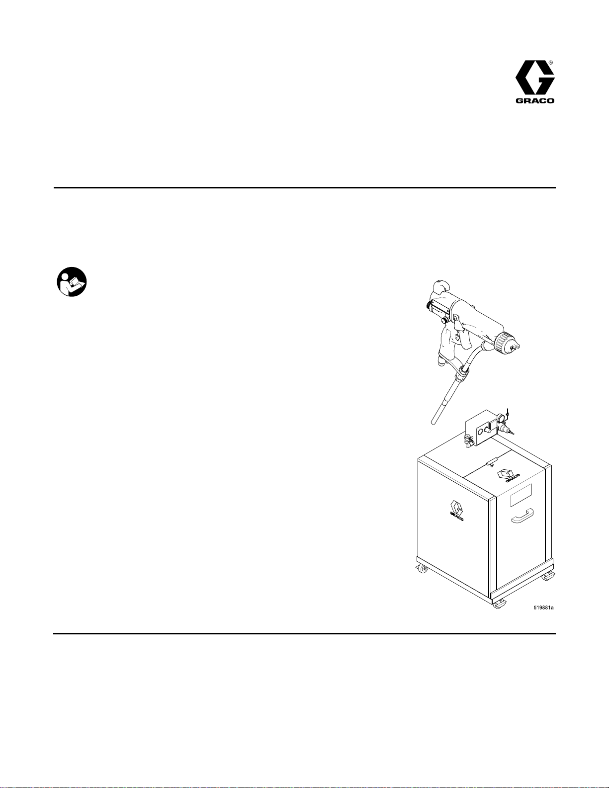
Instructions-Parts
WB100
WB100 WB100
Pro
Pro Pro
Air
Air Air
one
one one
For
For For
100 psi (0.7 MPa, 7.0 bar) Maximum
Fluid Working Pressure
100 psi (0.7 MPa, 7.0 bar) Maximum Air
Working Pressure
Xp™
Xp™ Xp™
spray
system
spray spray
system system
of
the
of of
professional
professional professional
conditions
the the
conditions conditions
Important
Important Important
Readallwarningsandinstructionsinthismanual.
Save
Save Save
Isolation
Isolation Isolation
60
60 60
for
use
for for
use use
for
for for
use
only.
use use
only. only.
Safety
Safety Safety
these
instructions.
these these
instructions. instructions.
WB
WB WB
when
when when
non
ammability
non non
- --ammability ammability
Instructions
Instructions Instructions
System
System System
and
and and
3A2496D
Gun
Gun Gun
electrostatically
electrostatically electrostatically
spraying
spraying spraying
listed
on
listed listed
on on
conductive,
conductive, conductive,
page
3.
page page
3. 3.
waterborne
waterborne waterborne
uids
that
uids uids
meet
that that
meet meet
EN
at
least
at at
least least
See
pages
See See
pages pages
part
numbers
part part
numbers numbers
information.
information. information.
and
3 33and and
and
and and
for
model
4 44for for
model model
approval
approval approval
PROVENQUALITY.LEADINGTECHNOLOGY.
Page 2

Contents
Contents Contents
Models...............................................................3
ModelswithFMApprovalOnly......................3
ModelswhichareFMApprovedand
CompliantwithEN50059.................4
Warnings...........................................................5
GunOverview....................................................8
HowtheElectrostaticSprayGun
Works............................................8
SprayingWaterborneFluids
Electrostatically..............................8
Controls,Indicators,andComponents...........8
SmartGuns.................................................10
Installation..........................................................16
SystemRequirements..................................16
WarningSign...............................................16
InstalltheSystem.........................................16
VentilatetheSprayBooth.............................16
AirSupplyLine............................................17
GroundtheCabinet......................................17
ConnecttheWaterborneFluidHose..............18
AgitatorKitAccessory..................................24
FluidRegulatorKitAccessory.......................25
GunSetup..........................................................26
SelectaFluidNozzleandAirCap.................26
Grounding...................................................26
CheckGunElectricalGrounding...................28
FlushBeforeUsingEquipment......................29
Operation...........................................................30
OperatingChecklist......................................30
FluidVoltageDischargeandGrounding
Procedure......................................30
PressureReliefProcedure............................31
FilltheFluidSupply......................................31
AdjusttheSprayPattern...............................32
Shutdown....................................................35
Maintenance......................................................36
Flushing......................................................36
CleantheGunDaily.....................................37
DailySystemCare.......................................38
ElectricalTests...................................................39
TestGunResistance....................................39
TestPowerSupplyResistance.....................40
TestElectrodeResistance............................41
TestGroundStripResistance.......................42
TestCylinderResistance..............................42
Troubleshooting..................................................43
VoltageLossTroubleshooting.......................43
SprayPatternTroubleshooting......................46
GunOperationTroubleshooting....................47
ElectricalTroubleshooting............................48
Repair................................................................50
PreparetheGunforService.........................50
AirCapandNozzleReplacement..................51
AirCap,SprayTip,andNozzle
Replacement(Model
L60M19)........................................52
ElectrodeReplacement................................54
NeedleReplacement(ModelL60M19)...........55
FluidPackingRodRemoval..........................56
PackingRodRepair.....................................57
BarrelRemoval............................................58
BarrelInstallation.........................................58
PowerSupplyRemovaland
Replacement..................................59
AlternatorRemovalandReplacement...........60
FanAirAdjustmentValveRepair..................62
AtomizingAirRestrictorValveRepair............63
ESOn-OffandFluidAdjustmentValve
Repair............................................64
AirValveRepair...........................................65
SmartModuleReplacement..........................66
AirSwivelandExhaustValve
Replacement..................................67
Parts..................................................................68
StandardWaterborneAirSprayGun
Assembly.......................................68
SmartWaterborneAirSprayGun
Assembly.......................................70
MoldReleaseSmartAirSprayGun
Assembly.......................................72
IsolationEnclosure.......................................74
TubingandWiring.......................................77
PackingRodAssembly.................................79
AlternatorAssembly.....................................80
ESOn-OffandFluidAdjustmentValve...........81
FanAirAdjustmentValveAssembly..............82
AtomizingAirRestrictorValve
Assembly.......................................82
AirCapAssembly........................................83
SmartModuleAssembly...............................84
AirCapsandFluidNozzles.................................85
SprayTipSelectionChart(ModelL60M19MRG
GunOnly).............................................90
RepairKits,RelatedManuals,and
Accessories..........................................92
Dimensions........................................................96
TechnicalData...................................................97
GracoProXpWarranty.......................................98
2
3A2496D
Page 3
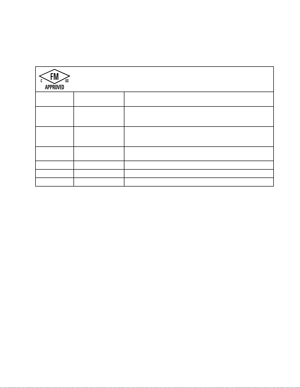
Models
Models
Models Models
Models
Models Models
Part
Part Part
24N580WB100WaterborneIsolationEnclosure233825withstandardelectrostatic
24P629WB100WaterborneIsolationEnclosure233825withsmartelectrostatic
233825WB100
L60T17ProXp60WB
L60M17ProXp60WB
24M732
with
FM
with with
No.
No. No.
Approval
FM FM
Approval Approval
Material
• ••Material Material
Model
Model Model
-——
Only
Only Only
FM
approved
FM FM
approved approved
does
not
does does
not not
for
use
with
uids
that
meet
the
for for
use use
with with
uids uids
that that
meet meet
sustain
sustain sustain
Sustained
Sustained Sustained
burning
burning burning
Burning
Burning Burning
Description
Description Description
airspraygunL60T17,groundedairhose235070,andshielded
waterborneuidhose24M732.
airspraygunL60M17,groundedairhose235070,andshielded
waterborneuidhose24M732.
WaterborneIsolationEnclosureforshieldedhoses.Doesnot
includehosesandgun.
StandardElectrostaticAirSprayGun,forwaterbornecoatings.
SmartElectrostaticAirSprayGun,forwaterbornecoatings.
ShieldedWaterborneFluidHoseAssembly,25ft(7.6m).
accordance
in ininaccordance accordance
Liquid
of ofofLiquid Liquid
with
with with
Mixtures,
Mixtures, Mixtures,
following
the the
following following
the
Standard
the the
Standard Standard
ASTM
ASTM ASTM
condition:
condition: condition:
Test
Method
Test Test
Method Method
D4206.
D4206. D4206.
for
for for
3A2496D 3
Page 4
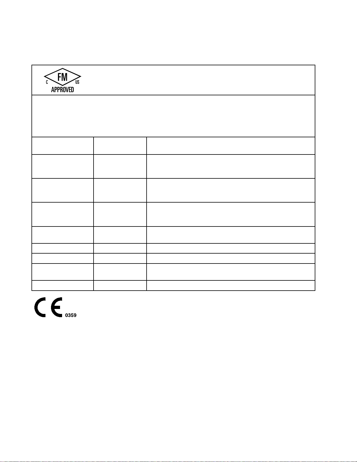
Models
Models
Models Models
Compliant
Compliant Compliant
FM12ATEX0080
FM12ATEX0080 FM12ATEX0080
Part
Part Part
24P630WB100WaterborneIsolationEnclosure246511withstandard
24P631WB100WaterborneIsolationEnclosure246511withsmartelectrostatic
24P734WB100
which
which which
0.35
0.35 0.35
J, J,J,with with
24M733
24M733 24M733
EN
50059
EN EN
50059 50059
Ta
0°C
Ta Ta
0°C 0°C
– ––50°C 50°C
No.
No. No.
are
FM
are are
with
EN50059
with with
EN50059 EN50059
with
Hose
Hose Hose
50°C
Approved
FM FM
Approved Approved
FM
approved
FM FM
approved approved
Material
• ••Material Material
Materials
• ••Materials Materials
does
does does
which
which which
Model
Model Model
and
and and
for
use
with
uids
that
meet
for for
use use
with with
uids uids
that that
not
sustain
not not
sustain sustain
for
Sustained
for for
Sustained Sustained
Models
Models Models
with
with with
cannot
cannot cannot
Description
Description Description
electrostaticairspraygunL60T18,groundedairhose235070,
andunshieldedwaterborneuidhose24M733.
airspraygunL60M18,groundedairhose235070,and
unshieldedwaterborneuidhose24M733.
WaterborneIsolationEnclosure246511withMRGsmart
electrostaticairspraygunL60M19,groundedairhose235070,
andunshieldedwaterborneuidhose24M733.
burning
burning burning
Burning
Burning Burning
Compliant
Compliant Compliant
uids
that
uids uids
that that
be
ignited,
be be
ignited, ignited,
accordance
in ininaccordance accordance
Liquid
of ofofLiquid Liquid
with
EN
with with
EN EN
meet
the
meet meet
the the
any
in ininany any
less
of ofofless less
mixture
mixture mixture
than
than than
the
meet meet
the the
with
with with
Mixtures,
Mixtures, Mixtures,
50059
50059 50059
following
following following
500
500 500
when
when when
with
with with
mJ.
mJ. mJ.
following
following following
the
the the
ASTM
ASTM ASTM
criteria:
criteria: criteria:
air,
air, air,
condition:
condition: condition:
Standard
Standard Standard
used
used used
by
by by
Test
Method
Test Test
Method Method
D4206.
D4206. D4206.
an
energy
an an
energy energy
source
source source
246511WB100
L60T18ProXp60WB
L60M18ProXp60WB
L60M19ProXp60WB
MRG
24M733
-——
WaterborneIsolationEnclosureforunshieldedhoses.Doesnot
includehosesandgun.
StandardElectrostaticAirSprayGun,forwaterbornecoatings.
SmartElectrostaticAirSprayGun,forwaterbornecoatings.
SmartElectrostaticAirSprayGun,formoldrelease
applications.
UnshieldedWaterborneFluidHoseAssembly,25ft(7.6m).
4
3A2496D
Page 5

Warnings
Warnings Warnings
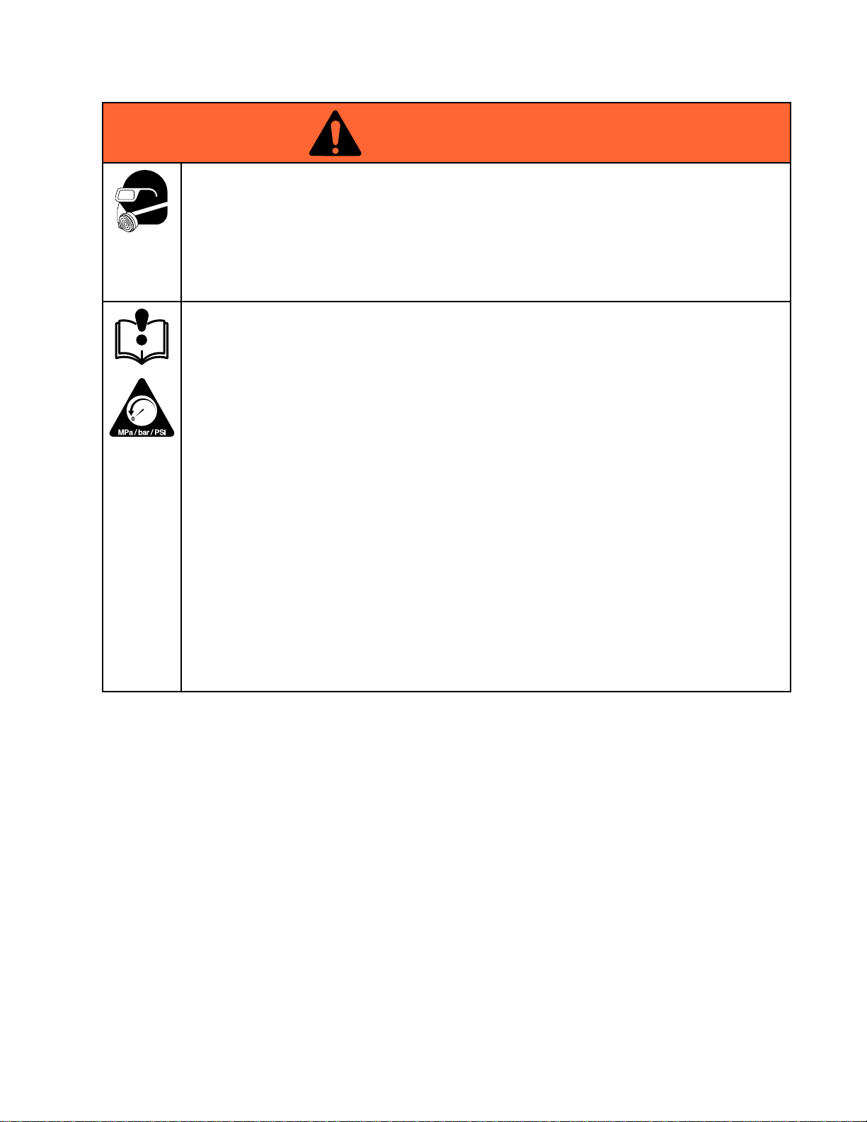
Thefollowingwarningsareforthesetup,use,grounding,maintenance,andrepairofthisequipment.The
exclamationpointsymbolalertsyoutoageneralwarningandthehazardsymbolsrefertoprocedure-specic
risks.Whenthesesymbolsappearinthebodyofthismanualoronwarninglabels,referbacktothese
Warnings.Product-specichazardsymbolsandwarningsnotcoveredinthissectionmayappearthroughout
thebodyofthismanualwhereapplicable.
WARNING
WARNING WARNING
ELECTRIC
ELECTRIC ELECTRIC
Impropergrounding,setup,orusageofanisolatedwaterbornesystemcanresultinelectric
shock.Tohelppreventelectricshock:
•Groundallequipment,personnel,objectbeingsprayed,andconductiveobjectsinorclose
tosprayarea.SeeGrounding Grounding
•Connecttheelectrostaticguntoavoltageisolationsystemthatwilldischargethesystem
voltagewhennotinuse.
•Allcomponentsoftheisolationsystemthatarechargedtohighvoltagemustbecontained
withinanisolationenclosurethatpreventspersonnelfrommakingcontactwiththehigh
voltagecomponentsbeforethesystemvoltageisdischarged.
•FollowtheFluid Fluid
thevoltage;beforecleaning,ushing,orservicingthesystem;beforeapproachingthefrontof
thegun;andbeforeopeningtheisolationenclosurefortheisolateduidsupply.
•Donotenterahighvoltageorhazardousareauntilallhighvoltageequipmenthasbeen
discharged.
•Donottouchthegunnozzleorelectrode,orcomewithin4in.(102mm)oftheelectrode
duringgunoperation.FollowtheFluid Fluid
•Interlockthegunairsupplywiththevoltageisolationsystemtoshutofftheairsupplyanytime
theisolationsystemenclosureisopened.
•Onlyusethered-coloredGracoelectricallyconductivegunairhosewiththisgun.Donot
useblackorgray-coloredGracoairhoses.
•Donotsplicehosestogether.InstallonlyonecontinuousGracowaterborneuidhose
betweentheisolateduidsupplyandthespraygun.
SHOCK
SHOCK SHOCK
Fluid
HAZARD
HAZARD HAZARD
Grounding
Voltage
Voltage Voltage
instructions.
Discharge
Discharge Discharge
and
Grounding
and and
Grounding Grounding
Fluid
Voltage
Voltage Voltage
Procedure
Procedure Procedure
Discharge
Discharge Discharge
and
and and
wheninstructedtodischarge
Grounding
Grounding Grounding
Procedure
Procedure Procedure
Warnings
.
3A2496D 5
Page 6
Warnings
WARNING
WARNING WARNING
FIRE
AND
FIRE FIRE
Combustibledustinwork work
•Fluidsusedmustmeetthefollowingammabilityrequirements:
Stop
•Stop Stop
equipmentuntilyouidentifyandcorrecttheproblem.
•Checkgunresistance,hoseresistance,andelectricalgroundingdaily.
•Useandcleanequipmentonlyinwellventilatedarea.
•Interlockthegunairsupplytopreventoperationunlessventilatingfansareon.
•Onlyusenon-ammablesolventswhenushingorcleaningequipment.
•Alwaysturntheelectrostaticsoffwhenushing,cleaningorservicingequipment.
•Eliminateallignitionsources;suchaspilotlights,cigarettes,portableelectriclamps,and
plasticdropcloths(potentialstaticarc).
•Donotplugorunplugpowercordsorturnlightsonoroffwhenammablefumesarepresent.
•Keepsprayareafreeofdebris,includingsolvent,ragsandgasoline.
•Keepaworkingreextinguisherintheworkarea.
PRESSURIZED
PRESSURIZED PRESSURIZED
Fluidfromtheequipment,leaks,orrupturedcomponentscansplashintheeyesoronskin
andcauseseriousinjury.
EXPLOSION
AND AND
EXPLOSION EXPLOSION
FM,
FMc
•FM, FM,
MaterialdoesnotsustainburninginaccordancewiththeStandardTestMethodfor
SustainedBurningofLiquidMixtures,ASTMD4206.
CE
•CE CE
Materialswhichcannotbeignited,inanymixturewithair,byanenergysourceof
lessthan500mJ.
operation
operation operation
Approved:
FMc FMc
Approved: Approved:
EN
50059
- --EN EN
50059 50059
immediately
immediately immediately
EQUIPMENT
EQUIPMENT EQUIPMENT
HAZARD
HAZARD HAZARD
work
area
area area
canigniteorexplode.Tohelppreventreandexplosion:
Compliant:
Compliant: Compliant:
ifstaticsparkingoccursoryoufeelashock.Donotuse
HAZARD
HAZARD HAZARD
•FollowthePressure Pressure
cleaning,checking,orservicingequipment.
•Tightenalluidconnectionsbeforeoperatingtheequipment.
•Checkhoses,tubes,andcouplingsdaily.Replacewornordamagedpartsimmediately.
PLASTIC
PLASTIC PLASTIC
Manysolventscandegradeplasticpartsandcausethemtofail,whichcouldcauseserious
injuryorpropertydamage.
•Useonlycompatiblewater-basedsolventstocleanplasticstructuralorpressure-containing
parts.
•SeeTechnical Technical
solventmanufacturer’sMSDSsandrecommendations.
TOXIC
TOXIC TOXIC
Toxicuidsorfumescancauseseriousinjuryordeathifsplashedintheeyesoronskin,
inhaled,orswallowed.
•ReadMSDSstoknowthespecichazardsoftheuidsyouareusing.
•Storehazardousuidinapprovedcontainers,anddisposeofitaccordingtoapplicable
guidelines.
Pressure
PARTS
PARTS PARTS
Technical
FLUID
FLUID FLUID
OR
OR OR
Relief
Procedure
Relief Relief
Procedure Procedure
CLEANING
CLEANING CLEANING
Data
Data Data
inthisandallotherequipmentinstructionmanuals.Readuidand
FUMES
FUMES FUMES
SOLVENT
SOLVENT SOLVENT
whenyoustopspraying/dispensingandbefore
HAZARD
HAZARD HAZARD
6 3A2496D
Page 7
Warnings
WARNING
WARNING WARNING
PERSONAL
PERSONAL PERSONAL
Wearappropriateprotectiveequipmentwhenintheworkareatohelppreventseriousinjury,
includingeyeinjury,hearingloss,inhalationoftoxicfumes,andburns.Thisprotective
equipmentincludesbutisnotlimitedto:
•Protectiveeyewear,andhearingprotection.
•Respirators,protectiveclothing,andglovesasrecommendedbytheuidandsolvent
manufacturer.
EQUIPMENT
EQUIPMENT EQUIPMENT
Misusecancausedeathorseriousinjury.
•Donotoperatetheunitwhenfatiguedorundertheinuenceofdrugsoralcohol.
•Donotexceedthemaximumworkingpressureortemperatureratingofthelowestrated
systemcomponent.SeeTechnical Technical
•Useuidsandsolventsthatarecompatiblewithequipmentwettedparts.SeeTechnical Technical
inallequipmentmanuals.Readuidandsolventmanufacturer’swarnings.Forcomplete
informationaboutyourmaterial,requestMSDSfromdistributororretailer.
•Donotleavetheworkareawhileequipmentisenergizedorunderpressure.
•TurnoffallequipmentandfollowthePressure Pressure
•Checkequipmentdaily.Repairorreplacewornordamagedpartsimmediatelywithgenuine
manufacturer’sreplacementpartsonly.
•Donotalterormodifyequipment.Alterationsormodicationsmayvoidagencyapprovals
andcreatesafetyhazards.
•Makesureallequipmentisratedandapprovedfortheenvironmentinwhichyouareusingit.
•Useequipmentonlyforitsintendedpurpose.Callyourdistributorforinformation.
•Routehosesandcablesawayfromtrafcareas,sharpedges,movingparts,andhotsurfaces.
•Donotkinkoroverbendhosesorusehosestopullequipment.
•Keepchildrenandanimalsawayfromworkarea.
•Complywithallapplicablesafetyregulations.
PROTECTIVE
PROTECTIVE PROTECTIVE
MISUSE
MISUSE MISUSE
EQUIPMENT
EQUIPMENT EQUIPMENT
HAZARD
HAZARD HAZARD
Technical
Data
Data Data
Pressure
inallequipmentmanuals.
Relief
Relief Relief
Technical
Procedure
Procedure Procedure
whenequipmentisnotinuse.
Data
Data Data
3A2496D
7
Page 8

GunOverview
Gun
Gun Gun
How
How How
Works
Works Works
Theairhosesuppliesairtothespraygun.Partof
theairoperatesthealternatorturbineandtherest
oftheairatomizestheuidbeingsprayed.The
alternatorgeneratespower,whichisconvertedby
thepowercartridgetosupplyhighvoltagetothe
gun’selectrode.
Thepumpsuppliesuidtotheuidhoseandgun,
wheretheuidiselectrostaticallychargedasit
passestheelectrode.Thechargeduidisattracted
tothegroundedworkpiece,wrappingaroundand
evenlycoatingallsurfaces.
Spraying
Spraying Spraying
Electrostatically
Electrostatically Electrostatically
Thiselectrostaticairspraygunisdesignedtospray
only
only only
ammabilityrequirements:
FM,
•FM, FM,
Materialdoesnotsustainburninginaccordance
withtheStandardTestMethodforSustained
BurningofLiquidMixtures,ASTMD4206.
CE-EN
•CE-EN CE-EN
Materialswhichcannotbeignited,inanymixture
withair,byanenergysourceoflessthan500mJ.
Whenconnectedtoavoltageisolationsystem,
alloftheuidinthespraygun,uidhose,and
Overview
Overview Overview
the
Electrostatic
the the
Electrostatic Electrostatic
Waterborne
Waterborne Waterborne
waterborneuidswhichmeetthefollowing
FMc
Approved:
FMc FMc
Approved: Approved:
50059
Compliant:
50059 50059
Compliant: Compliant:
Spray
Spray Spray
Fluids
Fluids Fluids
Gun
Gun Gun
isolateduidsupplyischargedtohighvoltage,
whichmeansthatthesystemhasmoreelectrical
energythanasolvent-basedsystem.Therefore,
onlynon-ammableuids(asdenedunder
Models,page3)canbesprayedwiththesystemor
beusedtoclean,ush,orpurgethesystem.
Precautionsmustbetakenwhenusingelectrostatic
waterborneequipmenttoavoidpotentialshock
hazards.Whenthespraygunchargestheisolated
uidtohighvoltage,itissimilartocharginga
capacitororabattery.Thesystemwillstoresomeof
theenergywhilesprayingandretainsomeofthat
energyafterthespraygunisshutoff.Donottouch
thegunnozzleorcomewithin4in.(102mm)of
theelectrodeuntilthestoredenergyisdischarged.
Theamountoftimeittakestodischargethe
energydependsonthesystemdesign.Followthe
FluidVoltageDischargeandGroundingProcedure,
page30,beforeapproachingthefrontofthegun.
NOTE:
NOTE: NOTE:
voidiftheelectrostaticspraygunisconnectedtoa
non-Gracovoltageisolationsystemorifthegunis
operatedabove60kV.
Controls,
Controls, Controls,
Theelectrostaticgunincludesthefollowing
controls,indicators,andcomponents(seeFig.
1).ForinformationonSmartguns,alsosee
SmartGuns,page10.
TheGracowarrantyandapprovalsare
Indicators,
Indicators, Indicators,
and
Components
and and
Components Components
8 3A2496D
Page 9
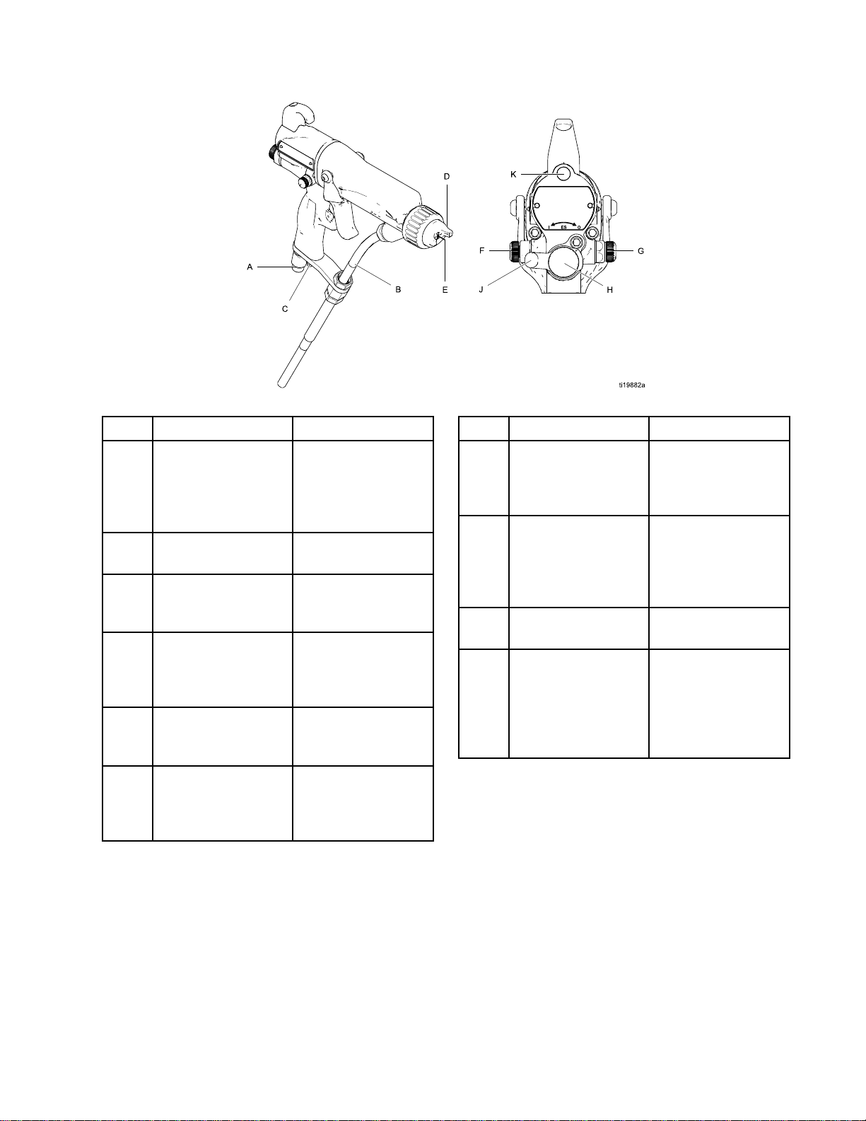
Figure1GunOverview
GunOverview
Item
Item Item
A
BFluidInlet
C
D
EElectrodeNeedle
FFanAirAdjustment
Description
Description Description
AirSwivelInlet1/4npsm(m)
TurbineAirExhaust
AirCapandNozzleSee
Valve
Purpose
Purpose Purpose
left-handthread,for
Gracored-colored
groundedairsupply
hose.
Gracowaterborne
uidsupplyhose
Barbedtting,for
suppliedexhaust
tube.
AirCapsandFluid
Nozzles,page85,
foravailablesizes.
Supplies
electrostaticcharge
totheuid.
Adjustsfansizeand
shape.Canbeused
todecreasepattern
width.
Item
Item Item
G
HFluidAdjustment
J
K
Description
Description Description
AtomizingAir
RestrictorValve
Knob
ESOn-OffValve
ESIndicator(standardgunonly;for
Smartgunindicator,seeOperating
Mode,page10)
Purpose
Purpose Purpose
Restrictsaircapair
ow.Replacewith
plug(included)if
desired.
Adjustsuidowby
limitinguidneedle
travel.Useonlyin
lowowconditions,
toreducewear.
Turnselectrostatics
ON(I)orOFF(O).
LitwhenESis
ON(I).Color
indicatesalternator
frequency.Seethe
LEDindicatortable
onpage36.
3A2496D 9
Page 10
GunOverview
Smart
Smart Smart
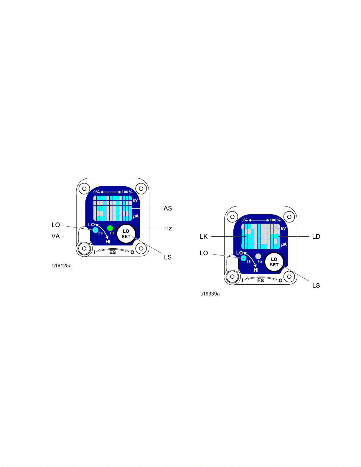
TheSmartGunmoduledisplayssprayingvoltage,
current,alternatorspeed,andthevoltagesetting(low
orhigh).Italsoallowstheusertochangetoalower
sprayingvoltage.Themodulehastwomodes:
•OperatingMode
•DiagnosticMode
Operating
Operating Operating
Bar
Bar Bar
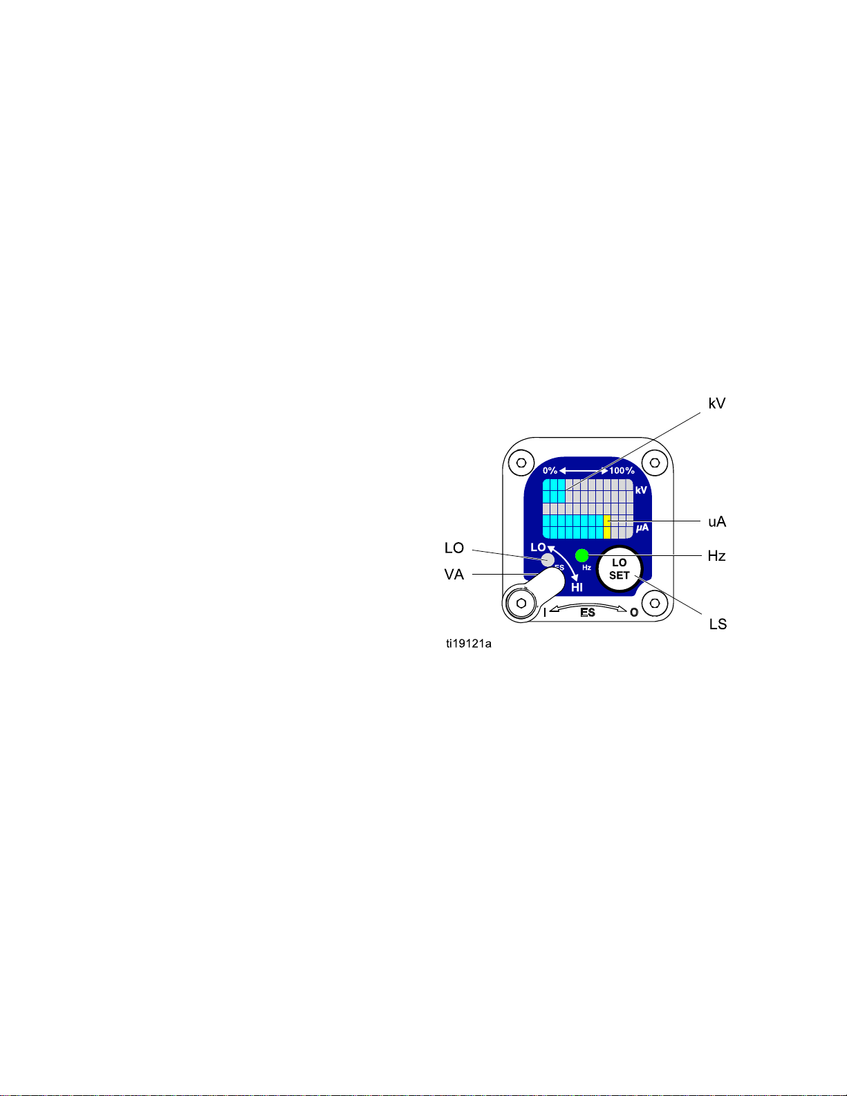
SeeFig.2,andTable1onpage12.TheOperating
Modedisplaysgundataduringnormalspraying.The
displayusesabargraphtoshowthevoltagelevelin
kiloVolts(kV)andthecurrentlevelinmicroAmperes
(uA).Thebargraphrangeisfrom0to100%foreach
value.
IfthebargraphLEDsareblue,thegunisreadyto
spray.IftheLEDsareyelloworred,thecurrentis
toohigh.Theuidmaybetooconductive,orsee
ElectricalTroubleshooting,page48forotherpossible
causes.
Guns
Guns Guns
Mode
Mode Mode
Graph
Graph Graph
Voltage
Voltage Voltage
Thevoltageadjustmentswitch(VA)allowsthe
operatortochangefromlowtohighvoltage.
•Thehighvoltagesettingisdeterminedbythe
maximumvoltageofthegunandisnotadjustable.
•Thelowvoltageindicator(LO)lights
whentheswitchissettoLO.Thelow
voltagesettingisuseradjustable.See
AdjustingtheLowVoltageSetting,page11.
NOTE:
NOTE: NOTE:
haslostcommunicationwiththepowersupply.See
ErrorDisplay,page11forfurtherinformation.
Adjustment
Adjustment Adjustment
IftheErrordisplayappears,theSmartmodule
Switch
Switch Switch
Hz
Indicator
Hz Hz
Indicator Indicator
TheHzindicatorfunctionsthesameastheES
indicatoronstandardguns.Theindicatorlightsto
showthealternatorspeedstatus,andhasthree
colors:
•Greenindicatesthealternatorspeediscorrect.
•Iftheindicatorchangestoamberafter1second,
increasetheairpressure.
•Iftheindicatorchangestoredafter1second,
reducetheairpressure.
Figure2SmartGunModuleinOperatingMode
10 3A2496D
Page 11
GunOverview
Error
Error Error
IftheSmartmodulelosescommunicationwith
thepowersupply,theErrordisplayappears,the
Hzindicatorturnsred,andtheSmartmoduleis
disabled.SeeFig.3,andTable1onpage12.
ThiscanoccurinOperatingModeorDiagnostic
Mode.SeeElectricalTroubleshooting,page48.
CommunicationmustberestoredtomaketheSmart
modulefunctional.
NOTE:
NOTE: NOTE:
appear.Ifthegunhasbeendisassembled,wait8
secondsbeforesprayingtoensurethatanError
conditionhasnotoccurred.
NOTE:
NOTE: NOTE:
displaywillnotappear.
Display
Display Display
Ittakes8secondsfortheErrordisplayto
Ifthereisnopowertothegun,theError
NOTE:
NOTE: NOTE:
returntotheOperatingScreen.
NOTE:
NOTE: NOTE:
LockSymbol,page11.
Figure4LowVoltageSettingScreen(Unlocked)
Lock
Lock Lock
Thelowvoltagesettingmaybelocked.Whenlocked,
animage(LK)appearsonthescreen.SeeFig.5,
andTable1onpage12.
After2secondsofinactivitythedisplaywill
Thelowvoltagesettingmaybelocked.See
Symbol
Symbol Symbol
Figure3ErrorDisplay
Adjusting
Adjusting Adjusting
Thelowvoltagesettingisuseradjustable.Toaccess
thelowvoltagesettingscreenwheninOperating
Mode,presstheLOSETbutton(LS)momentarily.
Thescreenwilldisplaythecurrentlowvoltage
setting.SeeFig.4,andTable1onpage12.The
rangeis30–60kV.
SettheVoltageAdjustmentswitch(VA)toLO.Press
theLOSETbuttonrepeatedlytoincreasethesetting
inincrementsof5.Whenthedisplayreachesthe
maximumsetting(60kV)itwillreturntotheminimum
setting(30kV).Continuepressingthebuttonuntil
youreachthedesiredsetting.
the
Low
the the
Voltage
Low Low
Voltage Voltage
Setting
Setting Setting
•WheninHImode,thelowvoltagesettingisalways always
locked.ThelocksymbolwillappearwhentheLO
SETbuttonispressed.
•WheninLOmode,thelocksymbolwill
only
only only
appearifthelockisenabled.See
LowVoltageLockScreen,page15,tolockor
unlockthelowvoltagesetting.
Figure5LowVoltageSettingScreen(Locked)
always
3A2496D
11
Page 12

GunOverview
Table
Table Table
Item
Item Item
VA
LO
kV
uA
LSLOSETbutton
Key
for
Figs.
1 11. ..Key Key
for for
2–9.
Figs. Figs.
2–9. 2–9.
Description
Description Description
VoltageAdjustmentSwitch
LowVoltageModeIndicator
Voltage(kV)Display
Current(uA)Display
Purpose
Purpose Purpose
Two-positionswitchsetssmart
gunvoltagetolowsetting(LO)or
highsetting(HI).Thisswitchis
functionalinOperatingModeand
inDiagnosticMode.
Lights(blue)whenthesmartgun
issettoLowVoltage.
Displaysactualsprayingvoltage
ofthegun,inkV.InOperating
Mode,displayisabargraph.
InDiagnosticMode,voltageis
displayedasanumber.
Displaysactualsprayingcurrent
ofthegun,inuA.InOperating
Mode,displayisabargraph.
InDiagnosticMode,currentis
displayedasanumber.
Pressmomentarilytoenterthe
LowVoltageSettingscreen.
Pressandholdforapproximately5
secondstoenterorexitDiagnostic
Mode.
WhileinDiagnosticMode,press
momentarilytoadvancethrough
screens.
WhileontheLowVoltageLock
Screen(inDiagnosticMode),
pressandholdtoturnthelockon
oroff.
LVLowVoltageDisplayDisplaysthelowvoltagesetting
asanumber.Thesettingcanbe
changed.SeeFig.4.
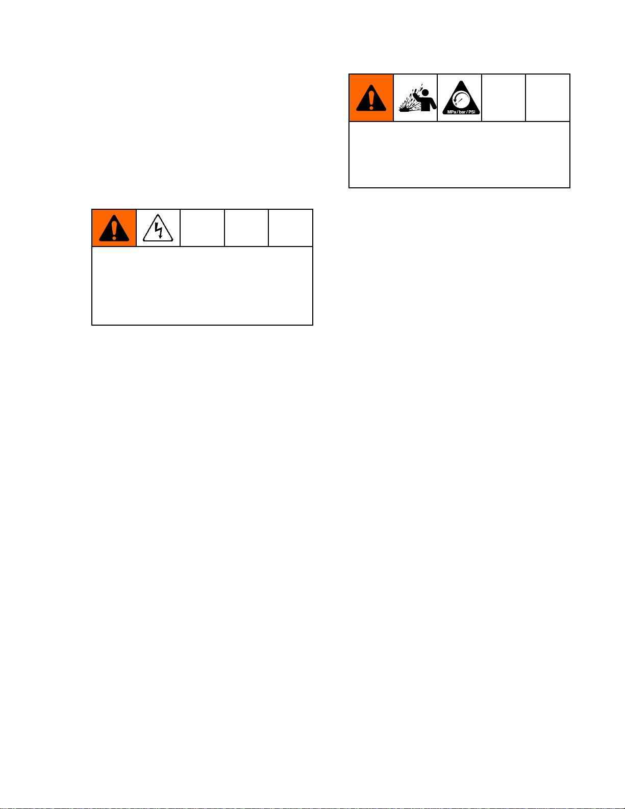
LKLowVoltageLocked
LD
ERErrorDisplay
VIVoltageIndicatorInDiagnosticMode,thetwotop
LODisplay
Appearsifthelowvoltagesetting
islocked.SeeFig.5andFig.9.
AppearsontheLowVoltageLock
Screen.SeeFig.9.
AppearsiftheSmartmoduleloses
communicationwiththepower
supply.SeeFig.3.
rightLEDsofthescreenlight,
indicatingthatthevaluedisplayed
isinkV.SeeFig.6.
12
3A2496D
Page 13

GunOverview
Item
Item Item
CICurrentIndicator
ASAlternatorSpeedDisplay
Hz
Description
Description Description
AlternatorSpeedIndicatorInOperatingMode,indicatorcolor
Purpose
Purpose Purpose
InDiagnosticMode,thetwo
bottomrightLEDsofthescreen
light,indicatingthatthevalue
displayedisinuA.SeeFig.7.
InDiagnosticMode,Hzlevelis
displayedasanumber.SeeFig.
8.
variestoshowthealternator
speedstatus:
•greenindicatesthealternator
speedisatthecorrectlevel.
•Iftheindicatorchangestoamber
after1second,thealternator
speedistoolow.
•Iftheindicatorchangestored
after1second,thealternator
speedistoohigh.Theindicator
willalsoturnrediftheError
displayappears.
InDiagnosticMode,theindicator
isgreenwhenintheAlternator
Speed(Hertz)screen.
3A2496D 13
Page 14

GunOverview
Diagnostic
Diagnostic Diagnostic
DiagnosticModeincludesfourscreenswhichdisplay
gundata:
•Voltage(kiloVolts)Screen
•Current(microAmperes)Screen
•AlternatorSpeed(Hertz)Screen
•LowVoltageLockScreen
NOTE:
NOTE: NOTE:
lowvoltagesetting;thesettingisnotadjustablein
DiagnosticMode.However,thevoltageadjustment
switch(VA)canbesettoHIorLOinOperatingMode
andDiagnosticMode.
ToenterDiagnosticMode,pressandholdtheLOSET
(LS)buttonforapproximately5seconds.Thedisplay
willgototheVoltage(kiloVolts)Screen,page14.
Toadvancetothenextscreen,presstheLOSET
buttonagain.
ToexitDiagnosticMode,pressandholdtheLOSET
buttonforapproximately5seconds.Thescreenwill
returntoOperatingMode.
NOTE:
NOTE: NOTE:
Mode,thelastscreenviewedwillbedisplayedwhen
thegunisretriggered.
NOTE:
NOTE: NOTE:
fromtheLowVoltageLockScreen.See
LowVoltageLockScreen,page15fordetails.
Voltage
Voltage Voltage
Mode
Mode Mode
YoumustbeinOperatingModetoadjustthe
IfthegunisdetriggeredwhileinDiagnostic
DiagnosticModecannotbeexited
(kiloVolts)
(kiloVolts) (kiloVolts)
Screen
Screen Screen
Figure6Voltage(kiloVolts)Screen
Current
Current Current
TheCurrent(microAmperes)Screenisthesecond
screenintheDiagnosticMode.SeeFig.7,andTable
1onpage12.Toenterthisscreen,presstheLO
SETbuttonwhileintheVoltage(kiloVolts)Screen.
Thisscreendisplaysthesprayingcurrentofthegun
asanumber(uA),roundedtothenearest5uA.The
twobottomrightLEDs(CI)ofthedisplaypanellight,
indicatingthattheCurrent(microAmperes)Screen
isdisplayed.Thedisplayisareadoutandcannot
bechanged.
PresstheLOSETbuttontoadvancetothe
AlternatorSpeed(Hertz)Screen,page15.Press
andholdforapproximately5secondstoreturnto
OperatingMode.
(microAmperes)
(microAmperes) (microAmperes)
Screen
Screen Screen
TheVoltage(kiloVolts)Screenistherstscreento
appearafterenteringDiagnosticMode.SeeFig.6,
andTable1onpage12.Toenterthisscreen,press
andholdtheLOSETbuttonforapproximately5
secondswhileintheOperatingMode.
Thisscreendisplaysthesprayingvoltageofthe
gunasanumber(kV),roundedtothenearest5kV.
ThetwotoprightLEDs(VI)ofthedisplaypanel
light,indicatingthattheVoltage(kiloVolts)Screen
isdisplayed.Thedisplayisareadoutandcannot
bechanged.
PresstheLOSETbuttontoadvancetothe
Current(microAmperes)Screen,page14.Press
andholdforapproximately5secondstoreturnto
OperatingMode.
14
Figure7Current(microAmperes)Screen
3A2496D
Page 15
GunOverview
Alternator
Alternator Alternator
TheAlternatorSpeed(Hertz)Screenisthethird
screenintheDiagnosticMode.SeeFig.8,andTable
1onpage12.Toenterthisscreen,presstheLOSET
buttonwhileintheCurrent(microAmperes)Screen.
Thisscreendisplaysthealternatorspeedasa3
digitnumber(AS),roundedtothenearest5Hz.The
displayisareadoutandcannotbechanged.Ifthe
alternatorspeedisgreaterthan999Hz,thedisplay
willshow999.
TheHzindicatorlightsgreentoshowthatyouare
viewingtheAlternatorSpeed(Hertz)Screen.
PresstheLOSETbuttontoadvancetothe
LowVoltageLockScreen,page15.Pressandhold
forapproximately5secondstoreturntoOperating
Mode.
Speed
Speed Speed
(Hertz)
(Hertz) (Hertz)
Screen
Screen Screen
Low
Voltage
Low Low
Voltage Voltage
TheLowVoltageLockScreenisthefourthscreenin
theDiagnosticMode.SeeFig.9,andTable1on
page12.Toenterthisscreen,presstheLOSET
buttonwhileintheAlternatorSpeed(Hertz)Screen.
ThisscreendisplaysthestatusoftheLowVoltage
Lock.Ifthesettingislocked,thelockimage(LK)
appearstotheleftoftheLodisplay(LD).Ifthesetting
isunlocked,thelockimagedoesnotappear.
Tochangethelockstatus,pressandholdthe
LOSETbuttonuntilthelockimageappearsor
disappears.Ifthelockisset,theimagewillalso
appearontheLowVoltageSettingScreenwhenin
lowvoltagemode(seeFig.4).
NOTE:
NOTE: NOTE:
screen,becausepressingandholdingtheLOSET
buttonisusedtoturnthelockonoroff.Toexit,
pressLOSETmomentarilytoreturntotheVoltage
(kiloVolts)Screen,thenexitDiagnosticModefrom
there.
DiagnosticModecannotbeexitedfromthis
Lock
Screen
Lock Lock
Screen Screen
Figure8AlternatorSpeed(Hertz)Screen
Figure9LowVoltageLockScreen
3A2496D 15
Page 16

Installation
Installation
Installation Installation
System
System System
AGracovoltageisolationsystemmusthavethe
followingfeatures:
•Anisolationenclosurethatpreventspersonsfrom
makingcontactwiththehighvoltagecomponents
beforethesystemvoltageisdischarged.All
componentsoftheisolationsystemthatare
chargedtohighvoltagemustbecontainedwithin
theenclosure.
•Ableedresistortodrainoffthesystemvoltage
whenthespraygunisnotinuse.Ametalpartof
theuidsupplyunitmustbeelectricallyconnected
tothebleedresistor.
•Asafetyinterlockthatautomaticallydischargesthe
systemvoltagewhenanyoneopenstheisolation
enclosure.
Thesystemshouldnothaveanyseverearcing
occurringwhentheisolationmechanismopens
andcloses.Severearcingwillshortenthelifeof
thesystemcomponents.
Requirements
Requirements Requirements
NOTICE
NOTICE NOTICE
Install
Install Install
Installingandservicingthisequipmentrequires
accesstopartswhichmaycauseelectricshock
orotherseriousinjuryifworkisnotperformed
properly.
•Donotinstallorservicethisequipmentunless
•Besureyourinstallationcomplieswithlocal,
Fig.19showsatypicalelectrostaticairspraysystem.
Itisnotanactualsystemdesign.Forassistance
indesigningasystemtosuityourparticularneeds,
contactyourGracodistributor.
Ventilate
Ventilate Ventilate
the
System
the the
System System
youaretrainedandqualied.
state,andnationalsafetyandrecodes,NFPA
33,NEC504and516,andOSHAstandard
1910.107.
the
Spray
the the
Spray Spray
Booth
Booth Booth
NOTE:
NOTE: NOTE:
voidiftheelectrostaticspraygunisconnectedtoa
non-Gracovoltageisolationsystemorifthegunis
operatedabove60kV.
Warning
Warning Warning
Mountwarningsignsinthesprayareawherethey
caneasilybeseenandreadbyalloperators.An
EnglishWarningSignisprovidedwiththegun.
TheGracowarrantyandapprovalsare
Sign
Sign Sign
Providefreshairventilationtoreducetheriskofre
orexplosioncausedbythebuildupofammableor
toxicvaporswhenspraying,ushing,orcleaning
thegun.Donotoperatethegununlessventilation
fansareoperating.
Checkandfollowalllocal,state,andnationalcodes
regardingairexhaustvelocityrequirements.
Highvelocityairexhaustwilldecreasetheoperating
efciencyoftheelectrostaticsystem.Theminimum
allowableairexhaustvelocityis60linearft/min(18.3
linearmeters/minute).
16 3A2496D
Page 17
Air
Supply
Air Air
Supply Supply
1.SeeFig.19.Installanairlinelter/water
separator(M)onthemainairsupplylineto
ensureadry,cleanairsupplytothegun.Dirtand
moisturecanruintheappearanceofyournished
workpieceandcancausetheguntomalfunction.
2.TheWB100systemincludesableed-typeair
regulator(N)onthegunairsupplyline(P),to
controlairpressuretothegun.
Toreducetheriskofelectricshockorother
seriousinjury,youmustusethered-colored
GracoElectricallyConductiveAirHoseforthe
gunairsupply,andyoumustconnectthehose
groundwiretoatrueearthground.Donotuse
theblackorgray-coloredGracoairhoses.
3.Connectthered-coloredGracoElectrically
ConductiveAirHose(P)betweenthegunair
regulator(N)andthegun’sairinlet.Thegunair
inletttinghasaleft-handthread.Connectthe
airsupplyhosegroundwire(Q)toatrueearth
ground.
Line
Line Line
Installation
Trappedaircancausetheuidsupplyunitto
cycleunexpectedly,whichcanresultinserious
injury,includingsplashinguidintheeyesor
ontheskin.Donotoperatetheequipment
withoutthebleed-typeairvalve(B)installed.
4.TheWB100systemincludesableed-typeair
valve(B).Thebleed-typeairvalveisrequired
toshutoffallairtothesystemandrelieveair
trappedbetweenthevalveandtheuidsupply
unitaftertheairregulatorisshutoff.Connectthe
mainairsupplyline(A)tothebleedvalve.
5.Installanadditionalbleed-typeairvalve(CC)
upstreamoftheairlter(M)toisolatethelter
forservicing.
Ground
Ground Ground
Connectthemaingroundwire(V)toatrueearth
ground.
the
Cabinet
the the
Cabinet Cabinet
3A2496D
17
Page 18
Installation
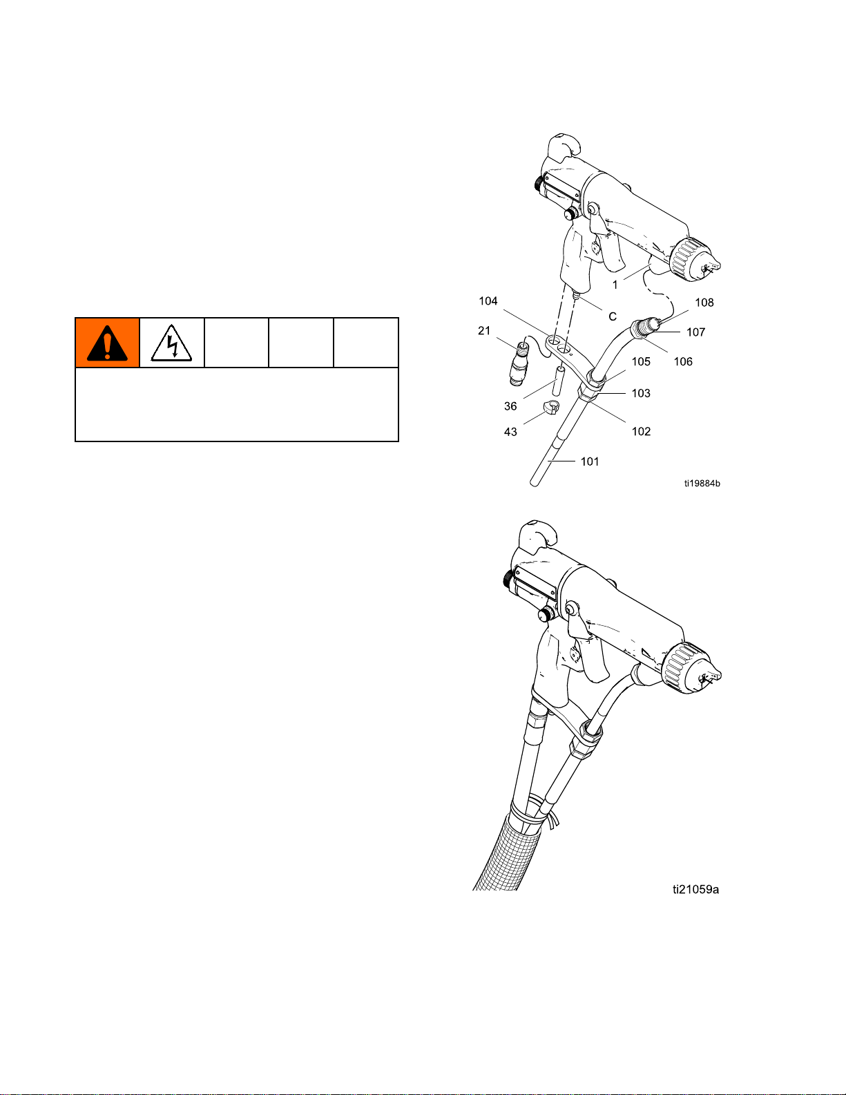
Connect
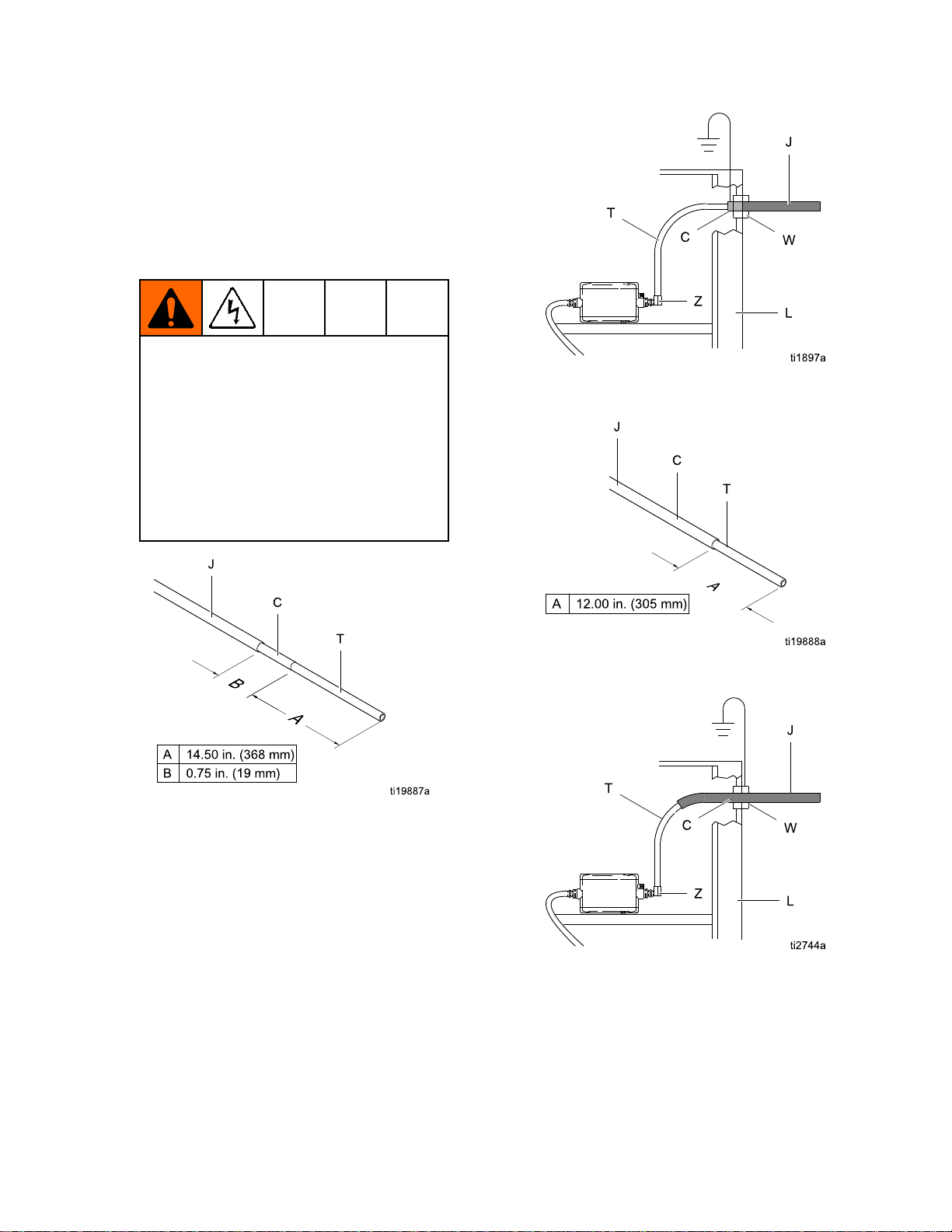
Connect Connect
AlwaysuseaGracowaterborneuidhosebetween
thevoltageisolationsystemuidoutletandthegun
uidinlet.Thewaterborneuidhose(101)consists
ofaninnerPTFEtube(T)andanabrasion-resistant
outerjacket(J).Shieldedhose24M732alsohas
aconductivelayer(C),Theconductivelayeris
connectedtogroundatthegunttingbracket(104).
Beforeconnectingthewaterborneuidhosetothe
gun,blowitoutwithairandushwithwaterto
removecontaminants.Flushthegunbeforeusingit.
Toreducetheriskofelectricshock,installonly
onecontinuousGracowaterbornehosebetween
theisolateduidsupplyandthegun.Donotsplice
hosestogether.
1.Removethegunairinlettting(21).
NOTE:
NOTE: NOTE:
failureoccurswherehighvoltagearcsthrough
theinnertube,voltagewillbedischargedto
groundthroughtheconductivehoselayer.When
properlyinstalled,theconductivehoselayeris
groundedthroughitsconnectiontothegrounded
enclosure.
the
Waterborne
the the
Waterborne Waterborne
Inashieldedhosesystem,ifahose
Fluid
Fluid Fluid
Hose
Hose Hose
Figure10ConnecttheFluidHose
Usingunshieldeduidhosesminimizesthe
systemcapacitance,resultinginfasterresponse
timesandalargereductionintheenergystored
inthesystem,ascomparedtoshieldedhoses.
However,withoutthegroundshield,aweak
staticchargecanoccasionallybuilduponthe
outersurfaceofthehose.Tominimizeany
staticchargefeltonthehosesurface,bundle
theairanduidhosetogether,andwrapwitha
protectivecover,asshown.
Figure11BundlingtheAirandFluidHoses
18 3A2496D
Page 19
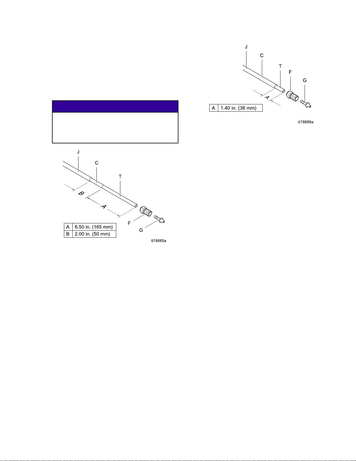
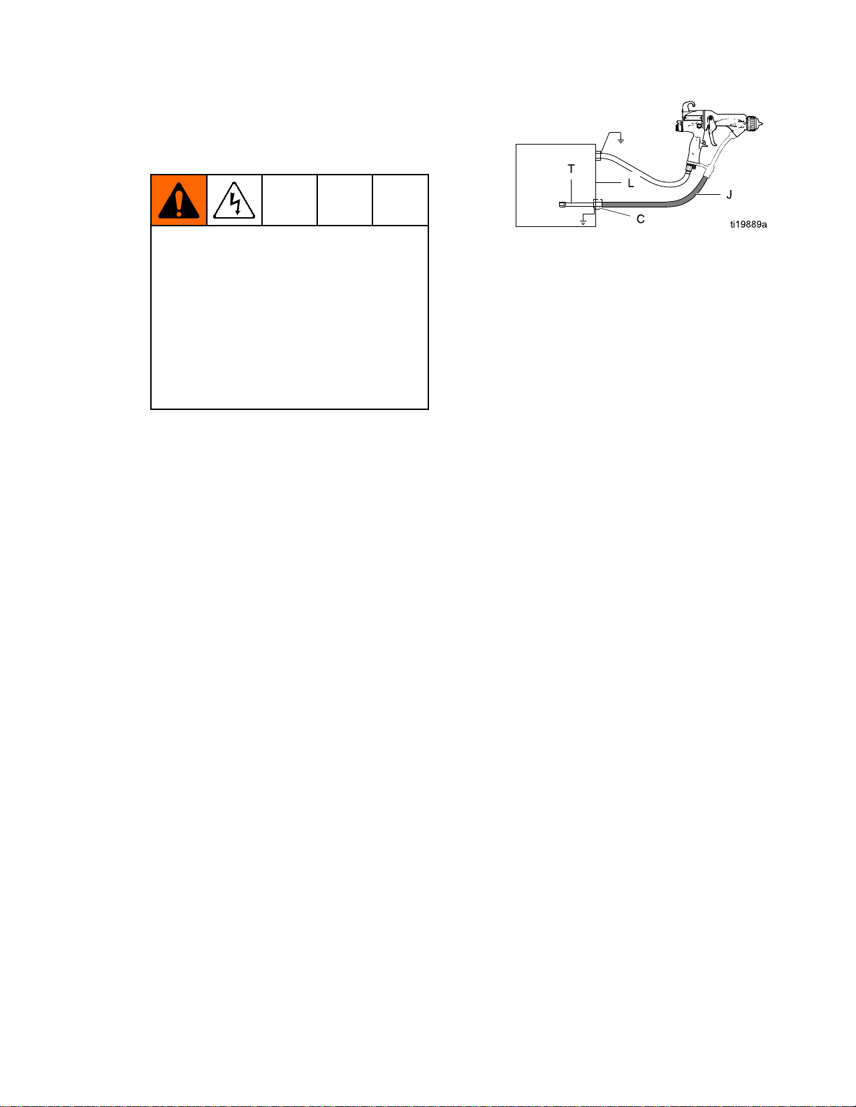
2.Fortheuidhosetotproperly,itmustbe
strippedandassembledtothedimensionsshown
inFig.12.Applydielectricgreasetotheinner
tube(T)ofthehose.Slidethetting(F)onto
thetube(T).Pressthebarbedtting(G)intothe
tubeuntilitsshoulderbottomsonthetube.A
newGracowaterborneuidhosecomesfully
assembledtothesedimensions.
NOTICE
NOTICE NOTICE
Becarefulnottocutintotheinnertube(T)of
thehosewhenstrippingthehose.Nicksor
cutsinthePTFEtubewillcausepremature
hosefailure.
Installation
Figure13UnshieldedHose24M733Dimensions
atGun
3.Generouslyapplydielectricgrease(44)tothe
o-ring(107)andthethreadsofthetting(106).
Pullthettingback1-1/2in.(38mm)andapply
greasetotheexposedPTFEhosetollthearea
betweenthehoseandthetting.Makesurethe
barrelinletiscleananddry,thenscrewthetting
intotheuidinletofthegunbarrel(1).
Figure12ShieldedHose24M732Dimensions
atGun
4.Loosenthestrainreliefnut(102)sothebracket
canmovefreelyonthehose.
5.Alignthebracket(104)holeswiththeairinletand
exhaustoutlet.Securewiththeairinlettting
(21).Tightenthestrainreliefnut(102)tosecure
thehose.
6.Checkthatthenut(105)istightenedsecurelyto
theferrulehousing(103).
7.Presstheexhausttube(36)ontotheexhaust
valvebarb(C).Securewiththeclamp(43).
3A2496D 19
Page 20
Installation
8.Connecttheotherendofthehosetotheisolated
uidsupplyasfollows:
Graco WB100 Enclosure:
a.
thestrainrelieftting(W).Ensureconductive
layer(C)haspassedthroughtting.Tighten
to55in-lb(6.2N•m).Pullbackonhose
tocheckitissecure.Complywiththe
requirementsintheWarning Warning
For
Shielded
For For
Shielded Shielded
Conductivehoselayer(C)mustbe
groundedthroughitsconnectiontothe
isolationsystem’sgroundedenclosure(L)
orgroundedfence.Tomaintaingrounding
continuity,theconductivehoselayer(C)
mustbeengagedintheferrulewhenthe
strainreliefnutistightened.Failureto
properlyinstallthehoseinthestrainrelief
couldresultinanelectricshock.
Warning
Hose
Systems:
Hose Hose
Systems: Systems:
Slidehosethrough
below.
Figure15ShieldedHose24M732
ConnectionatWB100Enclosure
Figure14ShieldedHose24M732
DimensionsatWB100Enclosure
Figure16UnshieldedHose24M733
DimensionsatWB100Enclosure
Figure17UnshieldedHose24M733
ConnectionatWB100Enclosure
20 3A2496D
Page 21
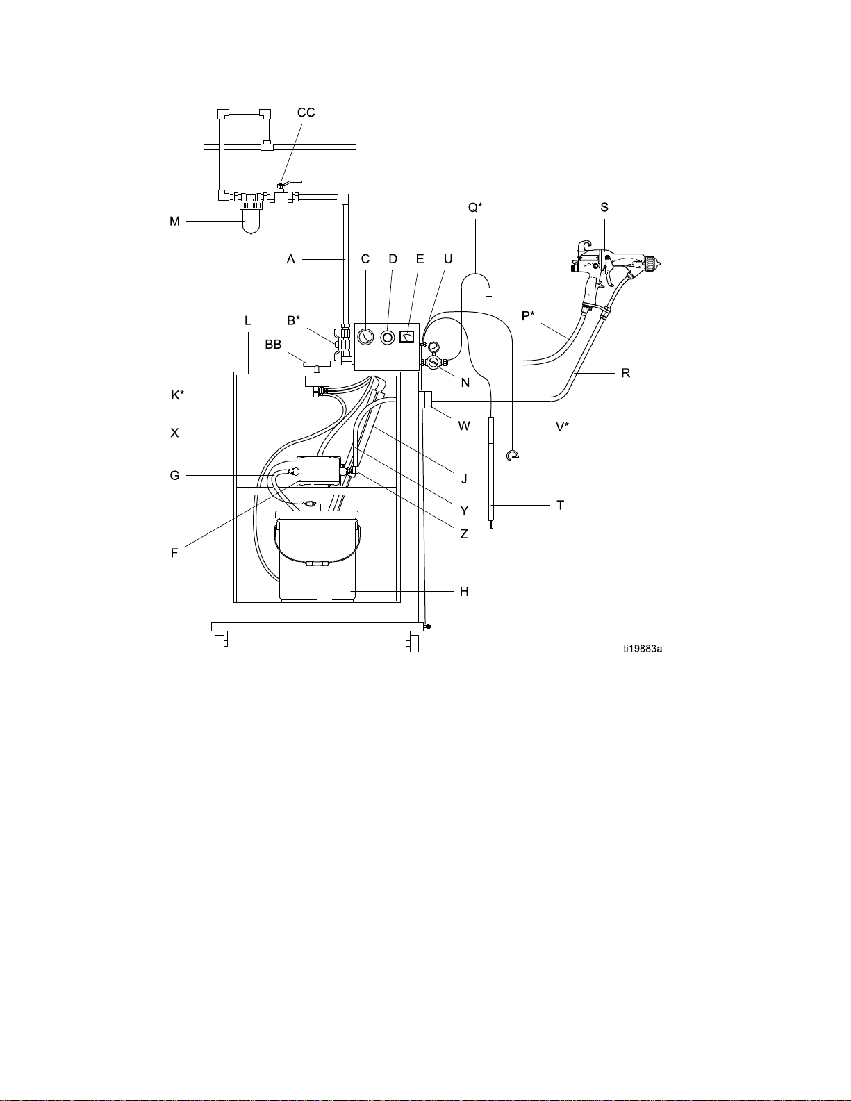
b.
Non-Graco Isolated Enclosure:
hoseasinstructedintheisolationsystem
manual,andcomplywiththerequirements
Warning
intheWarning Warning
For
Shielded
For For
Shielded Shielded
Conductivehoselayer(C)mustbe
groundedthroughitsconnectiontothe
isolationsystem’sgroundedenclosure(L)
orgroundedfence.Tomaintaingrounding
continuity,theconductivehoselayer(C)
mustbeengagedintheferrulewhenthe
strainreliefnutistightened.Failureto
properlyinstallthehoseinthestrainrelief
couldresultinanelectricshock.
below.
Hose
Systems:
Hose Hose
Systems: Systems:
Installation
Connect
Figure18ShieldedFluidHoseConnection
atNon-GracoIsolationEnclosure
c.Connecttheendofthetube(T)tothepump
uidoutlettting(Z).
NOTE:
NOTE: NOTE:
voidiftheelectrostaticspraygunisconnected
toanon-Gracovoltageisolationsystemorifthe
gunisoperatedabove60kV.
TheGracowarrantyandapprovalsare
3A2496D
21
Page 22
Installation
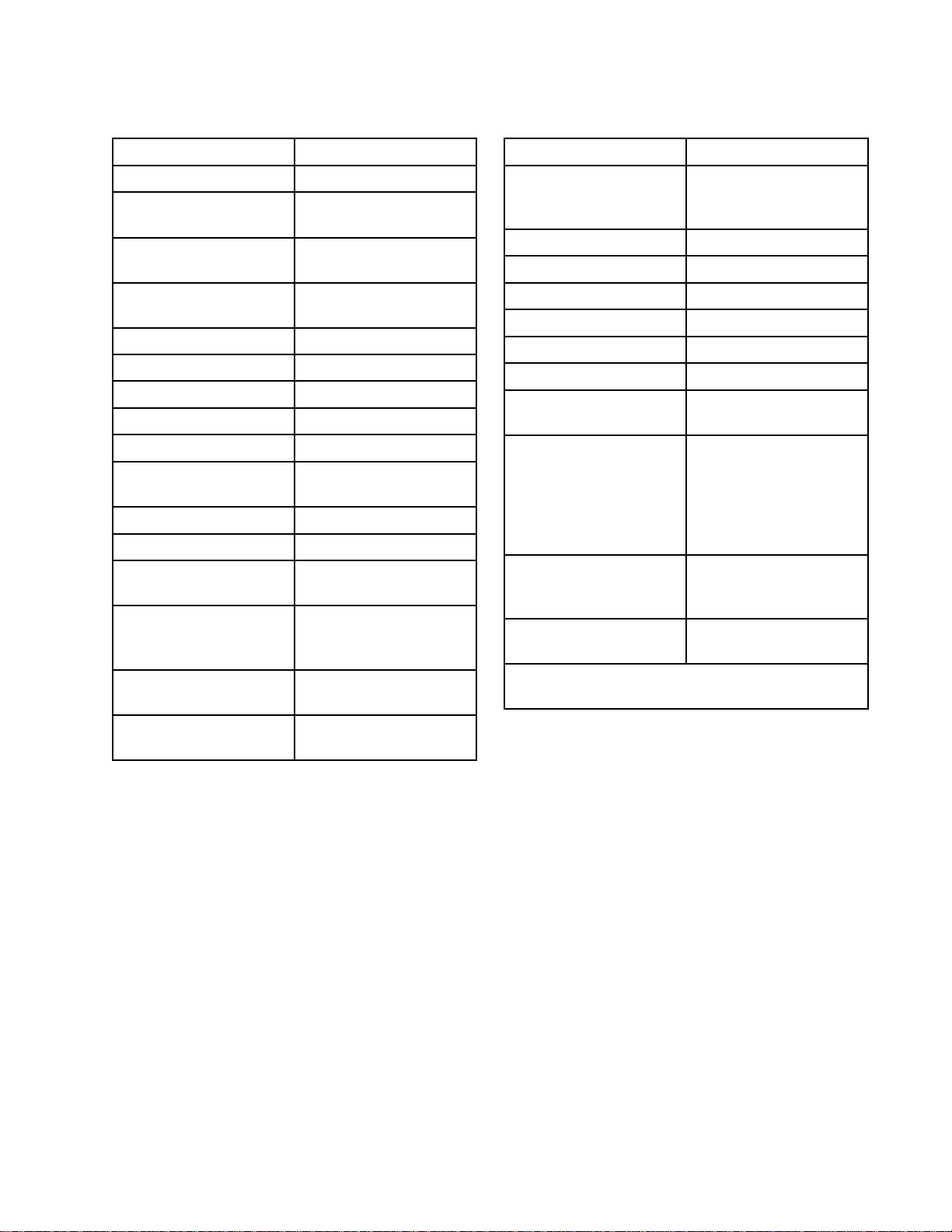
Figure19TypicalInstallation,ProXpWB100
WaterborneSystem
22
3A2496D
Page 23
Installation
Typical
Typical Typical
Installation
Installation Installation
Item
Item Item
A
B*Bleed-TypeAirShutoff
C
DPumpAirPressure
EkVMeter
FPump
GPumpSuctionHose
H
J*
K*EnclosureSafety
LIsolatedEnclosure
M
N
P*GracoRedGrounded
Q*GunAirHoseGround
Key
Key Key
Description
Description Description
MainAirSupplyLine
Valve
PumpAirPressure
Gauge
Regulator
PaintContainer
BleedResistor
Interlock
GunAirLineFilter
GunAirPressure
Regulator
AirHose(left-hand
threads)
Wire
Item
Item Item
S
T
U
V*MainGroundWire
W
X
Y
Z
AAIsolatedEnclosureDoor
BBEnclosureT-Handle
CC
*Theseitemsarerequiredforsafeoperation.They
areincludedwiththeWB100system.
Description
Description Description
Waterborne
ElectrostaticAirSpray
Gun
GroundingRod
GroundTerminal
StrainReliefFitting
PumpAirSupplyLine
GroundingCylinder
PumpFluidOutlet
Fitting
(notshown,toillustrate
internalcomponents.
Doormustbeclosed
andlockedtooperate
system).
LockingScrew(partof
doorassembly)
AccessoryBleed-Type
AirShutoffValve
R
GracoWaterborneFluid
Hose
3A2496D 23
Page 24
Installation
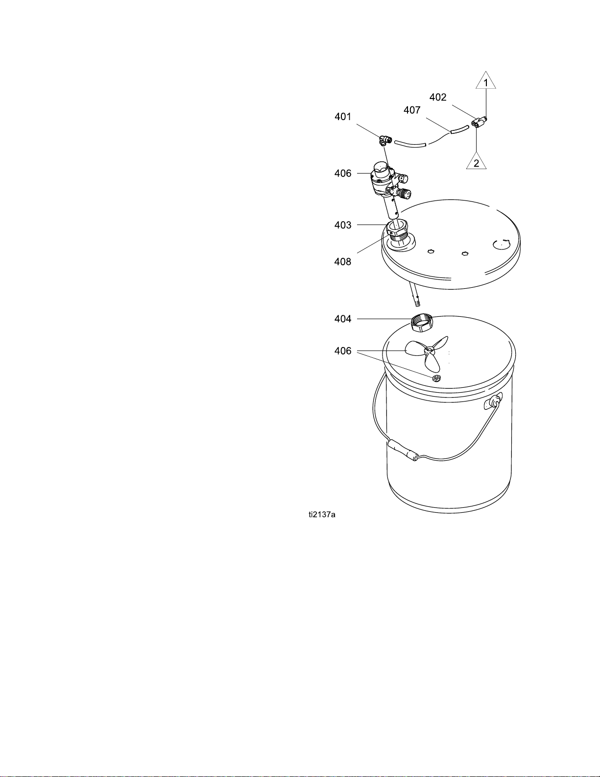
Agitator
Agitator Agitator
ToaddanagitatortotheGracoisolationsystem,order
PartNo.245895.See245895AgitatorKit,page94,
forthekitpartslist.
1.Dischargethesystemvoltage(seeFluidVoltage
DischargeandGroundingProcedure,page30).
2.Relievethepressure(see
PressureReliefProcedure,page31).
3.Opentheisolatedenclosuredoor.
4.Removethebackofthecontrolbox(258).
5.Removetube(A2)fromelbow(282)attheair
manifold;seeTubingandWiring,page77.
InstalltheYtting(402)intotheelbow.Install
tubes(A2)and(407)intotheYtting.Routethe
agitatortube(407)intothecabinet.
6.Replacethebackofthecontrolbox(258).
7.Assembletheotherpartsofthekitasshown.
Securetheagitatorwiththesetscrew(408).
8.Returnthesystemtoservice.
Kit
Accessory
Kit Kit
Accessory Accessory
Figure20245895AgitatorKit
24
3A2496D
Page 25
Installation
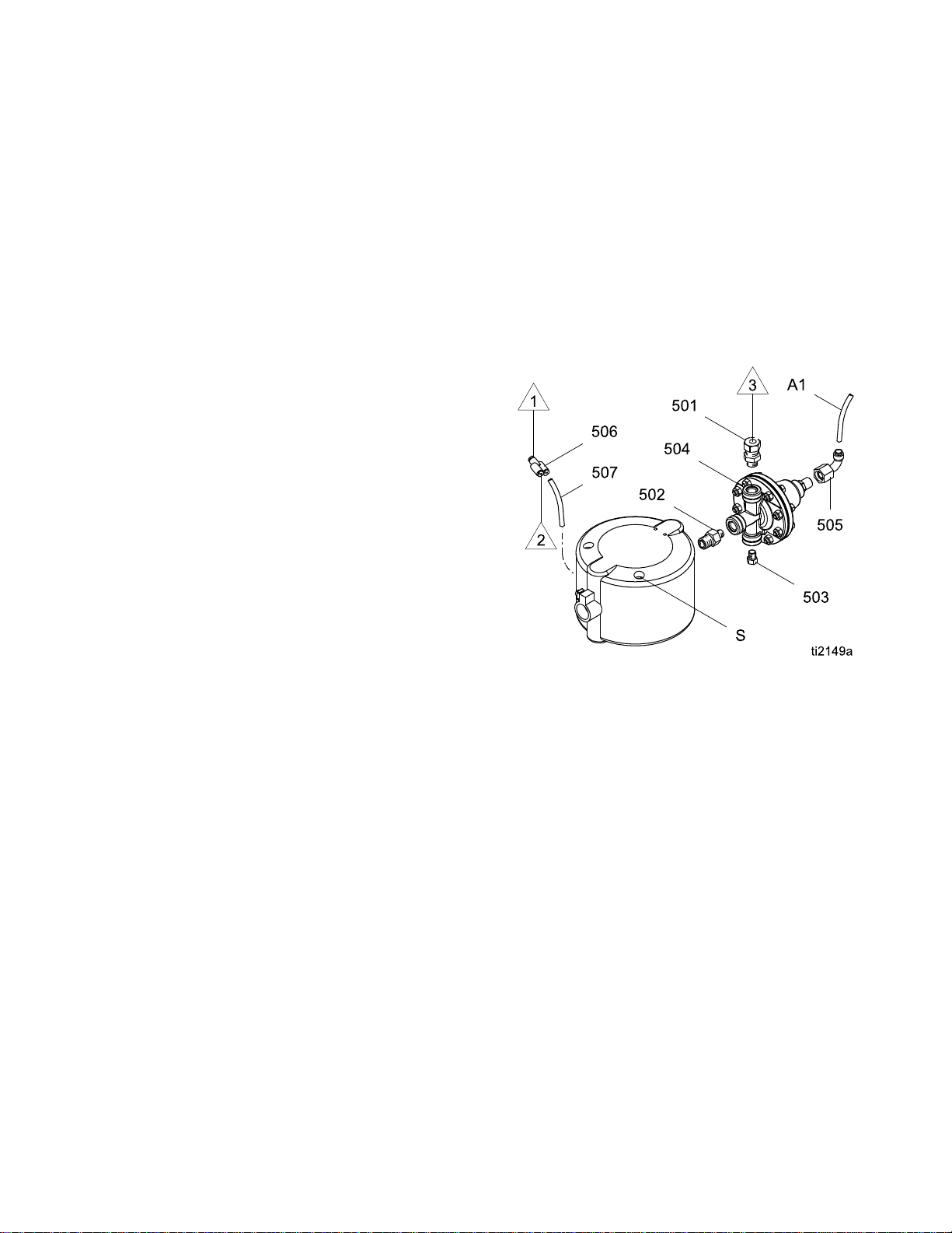
Fluid
Fluid Fluid
ToaddauidregulatortotheGracoisolation
system,orderPartNo.245944.See
245944FluidRegulatorKit,page95forthe
kitpartslist.
1.Dischargethesystemvoltage(seeFluidVoltage
2.Relievethepressure(see
3.Opentheisolatedenclosuredoor.
4.Removethe1/4in.(6mm)ODtube(A1)fromthe
5.Removethewaterborneuidhosefromthepump
6.Unscrewthetwopumpmountingscrews(S)and
7.Removethebackofthecontrolbox(258).
8.Removetube(A2)fromelbow(282)attheair
Regulator
Regulator Regulator
DischargeandGroundingProcedure,page30).
PressureReliefProcedure,page31).
pumpairinlet;seeTubingandWiring,page77.
uidoutlettting(231)andremovethetting.
removethepumpfromtheisolationenclosure.
manifold;seeTubingandWiring,page77.
InstalltheYtting(506)intheelbow.Install
tubes(A2)and(507)intotheYtting.Routethe
tube(507)intothecabinet.
Kit
Accessory
Kit Kit
Accessory Accessory
holesusedpreviously,toallowclearanceforthe
uidregulator.
12.Connecttube(A1)totheairinletofuidregulator
(504).Connecttube(507)tothepumpairinlet.
13.Connectthewaterborneuidhosetotheuid
regulatoroutlettting(501).
14.Returnthesystemtoservice.
NOTE:
NOTE: NOTE:
217)willnowoperatetheairpiloteduidregulator
(504).Thepumpwillnowoperateattheinletair
pressure.
Thecabinetairregulatorandgauge(216,
9.Replacethebackofthecontrolbox(258).
10.Assembletheuidregulatorkitasshown.
11.Reinstallthepumpintheisolationenclosure.
Usethetwomountingholestotheleftofthe
Figure21245944FluidRegulatorKit
3A2496D 25
Page 26
GunSetup
Gun
Gun Gun
Select
Select Select
Toreducetheriskofseriousinjury,including
splashinguidintheeyesorontheskin,follow
thePressureReliefProcedure,page31,before
removingorinstallingauidnozzleand/oraircap.
NOTE:
NOTE: NOTE:
aresuppliedwithPartNo.24N616Nozzle
and24N477AirCap.Ifyourequireadifferent
size,seeAirCapsandFluidNozzles,page85,
orconsultwithyourGracodistributor.See
AirCapandNozzleReplacement,page51.
ModelL60M19MoldReleaseGunissuppliedwith
PartNo.24N748Nozzle,24N727AirCap,anda
spraytipofchoice.Ifyourequireadifferentsize
spraytip,seeSprayTipSelectionChart(Model
L60M19MRGGunOnly),page90,orconsultwith
yourGracodistributor.SeeAirCap,SprayTip,and
NozzleReplacement(ModelL60M19),page52.
Setup
Setup Setup
Fluid
a aaFluid Fluid
StandardandSmartAirSprayGuns
Nozzle
Nozzle Nozzle
and
and and
Air
Cap
Air Air
Cap Cap
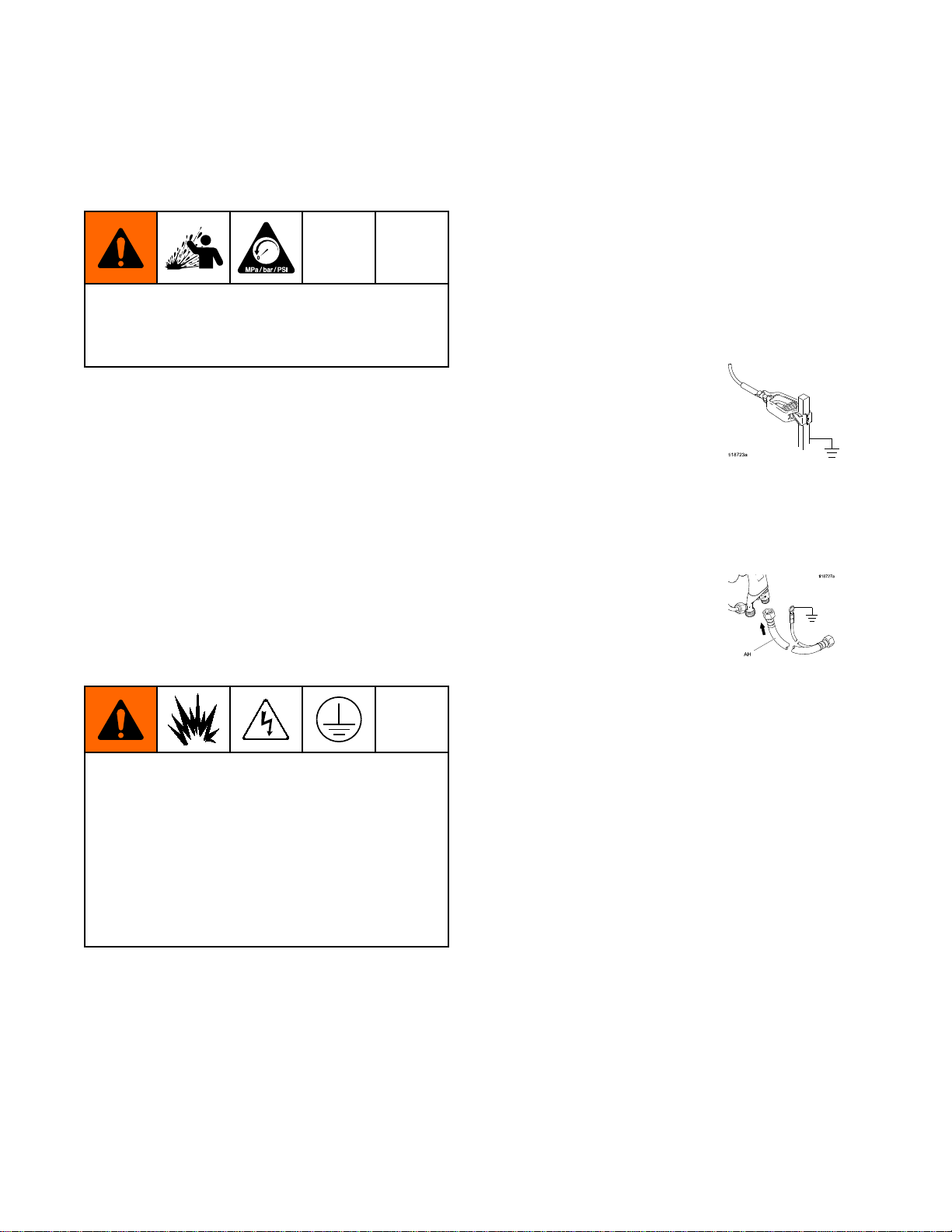
Thefollowingareminimumgroundingrequirements
forabasicelectrostaticwaterbornesystem.Your
systemmayincludeotherequipmentorobjectswhich
mustbegrounded.Checkyourlocalelectricalcode
fordetailedgroundinginstructions.Yoursystemmust
beconnectedtoatrueearthground.
Voltage Isolation System:
•
voltageisolationsystemtoatrueearthground.
SeeGroundtheCabinet,page17.
•
Electrostatic Air Spray Gun:
connectingthered-coloredGracoGrounded
AirHosetothegun,andconnectingtheair
hosegroundwiretoatrueearthground.See
CheckGunElectricalGrounding,page28.
Electricallyconnectthe
groundthegunby
Grounding
Grounding Grounding
Whenoperatingtheelectrostaticgun,any
ungroundedobjectsinthesprayarea(people,
containers,tools,etc.)canbecomeelectrically
charged.Impropergroundingcanresultinstatic
sparking,whichcancauseare,explosion,or
electricshock.Groundallequipment,personnel,
objectbeingsprayed,andconductiveobjects
inorclosetothesprayarea.Resistancemust
notexceed1megohm.Followthegrounding
instructionsbelow.
•
Graco Shielded Waterborne Fluid Hose
(24M732):
conductivelayer.Installasinstructedunder
ConnecttheWaterborneFluidHose,page18.
thehoseisgroundedthroughthe
26 3A2496D
Page 27
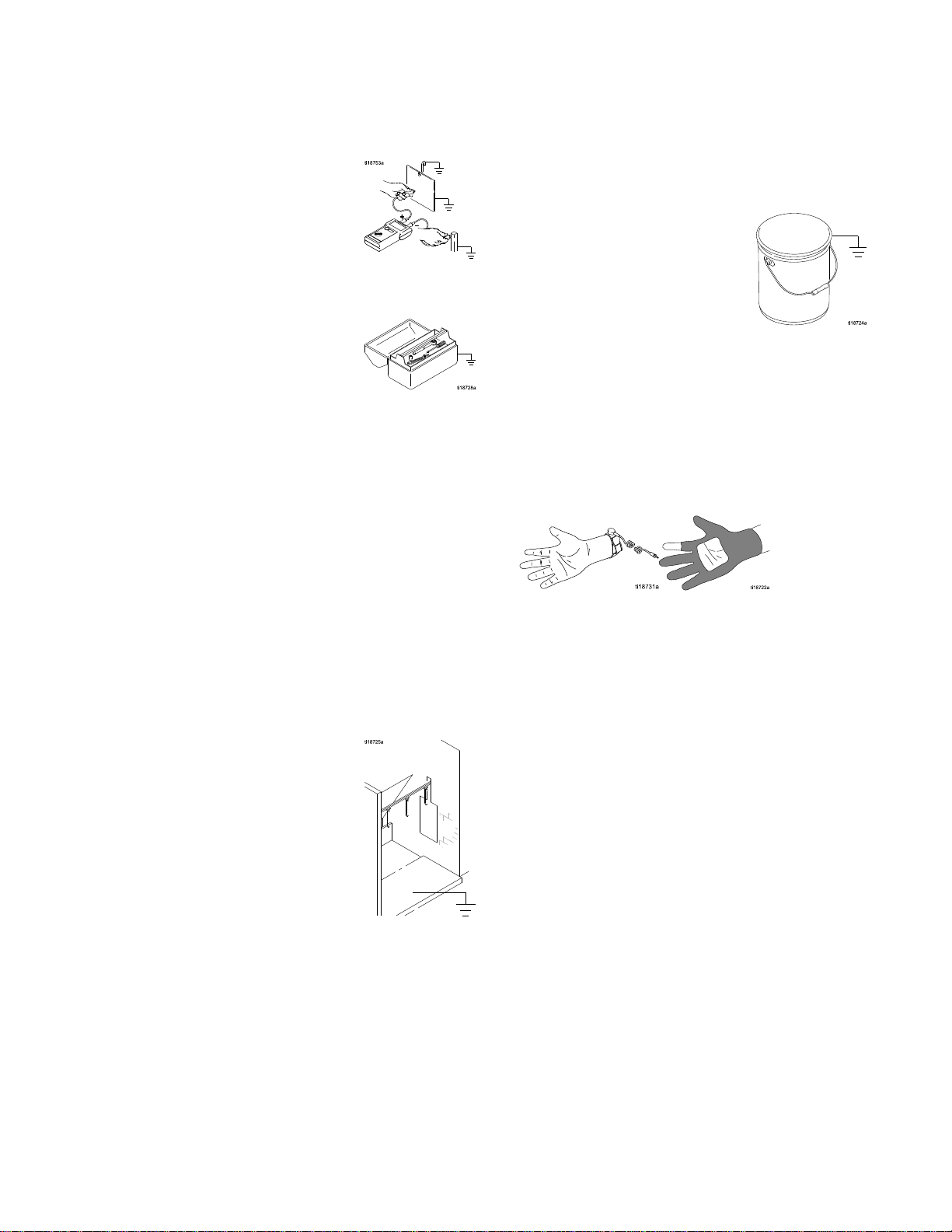
•
Object being sprayed:
cleanandgroundedatalltimes.
•
All electrically conductive objects or devices in the
spray area:
•
Fluid and waste containers:
wastecontainersinthesprayarea.Donotusepail
linersunlesstheyareconductiveandgrounded.
Whenushingthespraygun,thecontainerused
tocatchtheexcessuidmustbeelectrically
conductiveandgrounded.
mustbeproperlygrounded.
keeptheworkpiecehangers
groundalluidand
GunSetup
•
All solvent pails:
metalcontainers,whichareconductive.Donot
useplasticcontainers.Useonlynon-ammable
solvents.Donotstoremorethanthequantity
neededforoneshift.
•
All persons entering the spray area:
shoeshavingconductivesolessuchasleather,
orwearpersonalgroundingstraps.Donot
wearshoeswithnon-conductivesolessuchas
rubberorplastic.Ifglovesarenecessary,wear
theconductiveglovessuppliedwiththegun.If
non-Gracoglovesareworn,cutoffngersorpalm
areaofglovestoensureyourhandcontactsthe
groundedgunhandle.
useonlyapproved,grounded
mustwear
•
Air compressors:
tothemanufacturer'srecommendations.
All air lines
•
groundedhoseswithamaximumof100feet(30.5
m)combinedhoselengthtoensuregrounding
continuity.
•
The oor of the spray area:
conductiveandgrounded.Donotcovertheoor
withcardboardoranynon-conductivematerial
whichwouldinterruptgroundingcontinuity.
groundtheequipmentaccording
mustbeproperlygrounded.Useonly
mustbeelectrically
3A2496D
27
Page 28
GunSetup
Check
Check Check
MegohmmeterPartNo.241079(AA-seeFig.
21)isnotapprovedforuseinahazardousarea.
Toreducetheriskofsparking,donotusethe
megohmmetertocheckelectricalgrounding
unless:
•Thegunhasbeenremovedfromthehazardous
•Orallsprayingdevicesinthehazardousarea
Failuretofollowthiswarningcouldcausere,
explosion,andelectricshockandresultinserious
injuryandpropertydamage.
GracoPartNo.241079Megohmmeterisavailable
asanaccessorytocheckthatthegunisproperly
grounded.
Gun
Gun Gun
area;
areturnedoff,ventilationfansinthehazardous
areaareoperating,andtherearenoammable
vaporsinthearea(suchasopensolvent
containersorfumesfromspraying).
Electrical
Electrical Electrical
Grounding
Grounding Grounding
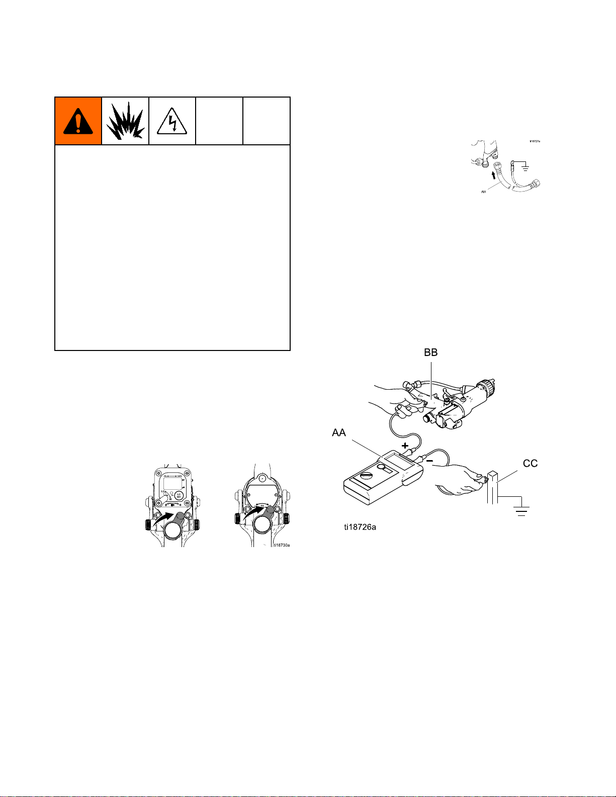
5.Makesurethered-coloredgroundedairhose
(AH)isconnectedandthehosegroundwireis
connectedtoatrueearthground.
6.Measuretheresistancebetweenthegunhandle
(BB)andatrueearthground(CC).Usean
appliedvoltageof500minimumto1000volts
maximum.Theresistanceshouldnotexceed
100ohms.SeeFig.22.
7.Iftheresistanceisgreaterthan100ohms,check
thetightnessofthegroundconnectionsandbe
suretheairhosegroundwireisconnectedtoa
trueearthground.Iftheresistanceisstilltoo
high,replacetheairhose.
1.Haveaqualiedelectricianchecktheelectrical
groundingcontinuityofthespraygunandair
hose.
2.TurnOFF(O)theESOn-Offswitch.
3.Turnofftheairanduidsupplytothegun.Follow
thePressureReliefProcedure,page31.The
uidhosemustnothaveanyuidinit.
4.Disconnecttheuidhose.
Figure22CheckGunElectricalGrounding
28 3A2496D
Page 29
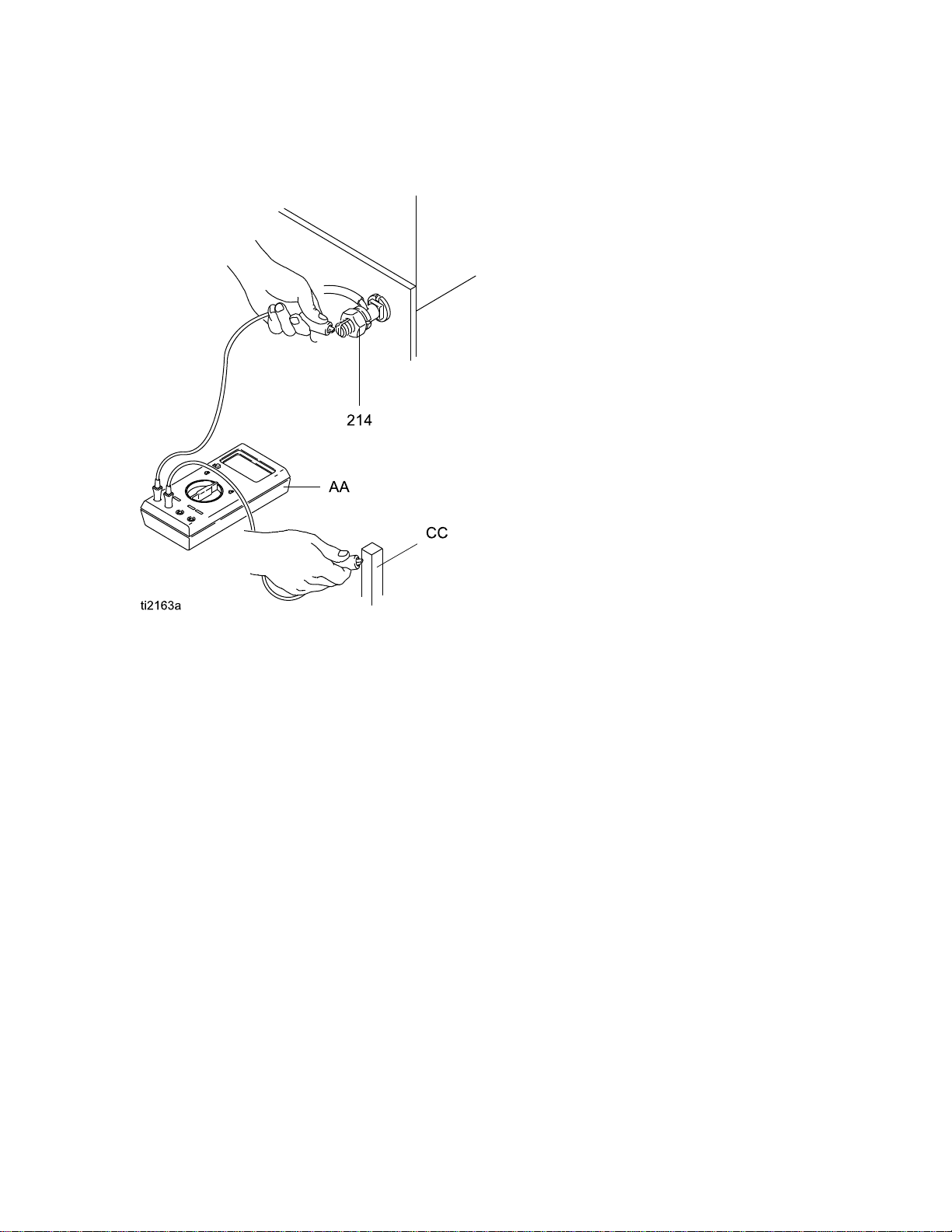
8.Usinganohmmeter(AA)measuretheresistance
betweenthecabinetgroundlug(214)andatrue
earthground(CC).Theresistancemustbeless
than100ohms.
GunSetup
Figure23CheckCabinetGrounding
Flush
Flush Flush
Theequipmentwastestedinuidatthefactory.To
avoidcontaminatingyouruid,ushtheequipment
withacompatiblesolventbeforeusingtheequipment.
Before
Before Before
Using
Using Using
Equipment
Equipment Equipment
3A2496D 29
Page 30
Operation
Operation
Operation Operation
Operating
Operating Operating
Checkthefollowinglistdaily,beforestartingthe
system.
Alloperatorsareproperlytrainedtosafely
operateanelectrostaticwaterborneairspray
systemasinstructedinthismanual.
Alloperatorsaretrainedinthe
PressureReliefProcedure,page31.
Theelectrostaticsareturnedoffandsystem
voltageisdischargedaccordingtothe
FluidVoltageDischargeandGrounding
Procedure,page30,beforeanypersonen-
terstheisolationenclosure,beforecleaning,
andbeforeperforminganymaintenanceor
repair.
Thesystemisgroundedaccordingtothe
instructionsinGrounding,page26.
Checklist
Checklist Checklist
Fluid
Fluid Fluid
Grounding
Grounding Grounding
Theuidsupplyischargedwithhighvoltageuntil
thevoltageisdischarged.Contactwiththecharged
componentsofthevoltageisolationsystemor
spraygunelectrodewillcauseanelectricshock.
Toavoidanelectricshock,followtheFluid Fluid
Discharge
Discharge Discharge
•wheneveryouareinstructedtodischargethe
•beforecleaning,ushing,orservicingthesystem
•beforeapproachingthefrontofthegun
•orbeforeopeningtheisolationenclosureforthe
1.TurntheESON/OFFvalveOFFandwait30
voltage
equipment
isolateduidsupply.
seconds.
Voltage
Voltage Voltage
and
and and
Discharge
Discharge Discharge
Procedure
Procedure Procedure
Grounding
Grounding Grounding
Procedure:
Procedure: Procedure:
and
and and
Fluid
Voltage
Voltage Voltage
TheGracowaterborneuidhoseisingood
conditionwithnocutsorabrasionsofthe
PTFElayer.Replacehoseifdamaged.
Ventilationfansareoperatingproperly.
Alldebris,includingammableuidsand
rags,isremovedfromthesprayarea.
Fluidsusedmustmeetthefollowing
ammabilityrequirements:
FM,
FMc
•FM, FM,
Materialdoesnotsustainburningin
accordancewiththeStandardTestMethod
forSustainedBurningofLiquidMixtures,
ASTMD4206.
CE
•CE CE
Materialswhichcannotbeignited,inany
mixturewithair,byanenergysourceof
lessthan500mJ.
Approved:
FMc FMc
Approved: Approved:
EN
50059
- --EN EN
50059 50059
Compliant:
Compliant: Compliant:
2.FullyunscrewthedoorT-handlelockingscrew.
Thiswillshutofftheairtothegunandtriggerthe
groundingcylindertodischargeanyremaining
electricalcharge.
3.Usethegroundingrodtotouchthepump
andsupplypail.Ifyouseeanyarcs,see
ElectricalTroubleshooting,page48.
30 3A2496D
Page 31

Operation
Pressure
Pressure Pressure
1.TurnOFF(O)theESOn/Offswitch.
2.FollowtheFluidVoltageDischargeand
GroundingProcedure,page30.
3.Turnofftheairbleedvalvestotheuidsource
andtothegun.
Relief
Relief Relief
Procedure
Procedure Procedure
Fill
the
Fill Fill
1.FollowtheFluidVoltageDischargeand
2.FollowthePressureReliefProcedure,page31.
3.Opentheisolatedenclosuredoor.
4.Removethepailcoverfromthepail,holdingarag
5.Removethesupplypailfromtheenclosure.
6.Cleanupanyuidspillsintheenclosure,using
7.Fillthesupplypailwithuidandreturnittothe
Fluid
the the
Fluid Fluid
GroundingProcedure,page30.
overthesuctiontubestrainertopreventanyuid
fromdrippingintotheisolatedenclosure.Place
thecoverandsuctiontubeoutsidetheenclosure.
Besuretowipeupalluidspillsintheisolated
enclosure.Fluidcancreateaconductivepath
andcausethesystemtoshortout.
asoftclothandanon-ammable,compatible
solvent.
enclosure.Cleanupanyspills.
Supply
Supply Supply
NOTICE
NOTICE NOTICE
4.Triggerthegunintoagroundedmetalwaste
containertorelievetheuidpressure.
5.Relieveuidpressureintheuidsupplyunitas
instructedinyouruidsupplyunitmanual.
8.Reinstallthepailcover,holdingaragoverthe
suctiontubestrainertopreventuidspillswhile
youplacethepumpsuctiontubeinthepail.
9.Closetheisolatedenclosuredoorandfasten
securelywiththeT-handlelockingscrew.
3A2496D 31
Page 32

Operation
Adjust
Adjust Adjust
Toreducetheriskofreandexplosion,uidsused
mustmeetthefollowingammabilityrequirements:
•FM, FM,
•CE CE
Contactwiththechargedcomponentsofthespray
gunwillcauseanelectricshock.Donottouchthe
gunnozzleorelectrodeorcomewithin4in.(102
mm)ofthefrontofthegunduringoperationor
untilperformingtheFluidVoltageDischargeand
GroundingProcedure,page30.
FollowtheFluidVoltageDischargeandGrounding
Procedure,page30whenyoustopsprayingand
wheneveryouareinstructedtodischargethe
voltage.
Toreducetheriskofcomponentrupture,which
cancauseseriousinjury,donotexceedthe
maximumworkingpressureofthelowestrated
systemcomponent.Thisequipmenthasa100psi
(0.7MPa,7bar)maximumworkingairanduid
pressure.
the
Spray
the the
Spray Spray
FM,
FMc
Approved:
FMc FMc
Approved: Approved:
Materialdoesnotsustainburninginaccordance
withtheStandardTestMethodforSustained
BurningofLiquidMixtures,ASTMD4206.
CE
EN
50059
- --EN EN
50059 50059
Materialswhichcannotbeignited,inanymixture
withair,byanenergysourceoflessthan500mJ.
Pattern
Pattern Pattern
Compliant:
Compliant: Compliant:
Followthestepsbelowtoestablishthecorrect
uidowandairow.SeeFig.24tolocatethe
electrostaticguncontrols.
Figure24ElectrostaticGunControls
1.Thegunisshippedwiththeuidnozzleandair
capinstalled.Checkthattheretainingringis
tight.
NOTE:
NOTE: NOTE:
oraircap,seeFluidNozzleSelectionChart,
page85andAirCapSelectionChart,page87.
Toinstallthenozzleandaircap,see
AirCapandNozzleReplacement,page51.Model
L60M19MoldReleaseGunissuppliedwithPart
No.24N748Nozzle,24N727AirCap,anda
spraytipofchoice.Ifyourequireadifferentsize
spraytip,seeSprayTipSelectionChart(Model
L60M19MRGGunOnly),page90,orconsult
withyourGracodistributor.Toinstallthetip,see
AirCap,SprayTip,andNozzleReplacement
(ModelL60M19),page52.
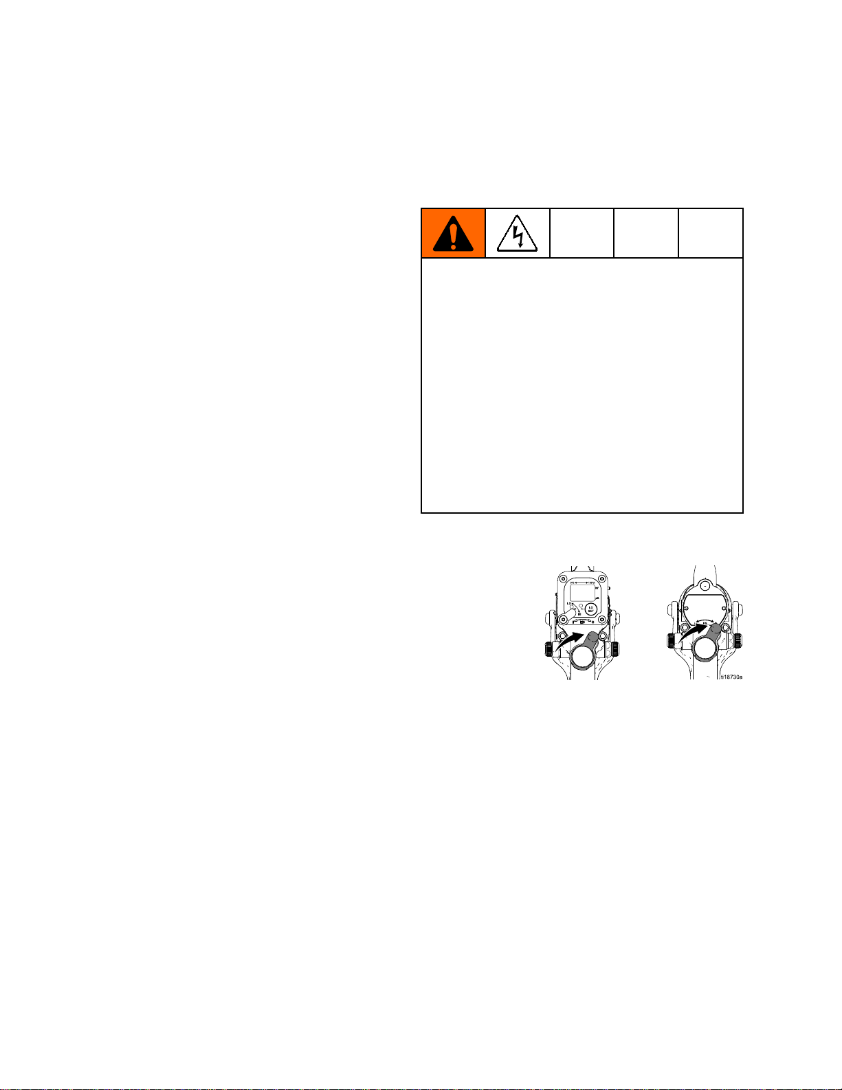
2.TurnOFF(O)theESOn-Offswitch(J).
Toselectadifferentsizeuidnozzle
Toreducetheriskofaninjury,followthe
PressureReliefProcedure,page31wheneveryou
areinstructedtorelievethepressure.
3.Turnonthemasterairbleedvalvetothegun.
32 3A2496D
Page 33

Operation
4.Positiontheaircapbylooseningtheaircap
retainingring,androtatingtheaircapfora
verticalorhorizontalspraypattern.Tightenthe
retainingringuntiltheaircapisheldrmlyin
place;youshouldnotbeabletorotatetheair
caphornsbyhand.
5.Fullyopenthefanairadjustmentvalve(F)
counterclockwise.
6.Fullyopentheuidadjustmentvalve(H)
counterclockwise.
8.MakesuretheESOn-Offswitch(J)isOFF(O).
9.Adjustthepumpairregulatortostarttheuid
supplyunit.Adjusttheuidowwiththeair
pressureregulatoruntilthestreamfromthegun
travels8-12in.(200-300mm)beforefallingoff.
Typically,ifuidpressureisbelow5psi(.04
MPa,0.4bar)orabove30psi(0.21MPa,2.1
bar),achangeofnozzlesizeisrecommended.
10.Setthegunairregulatortodeliveraminimum
45psi(0.32MPa,3.2bar)atthegunwhen
triggered,toensurefullsprayingvoltage.See
thetablebelow.
7.Fullyopentheatomizingairrestrictorvalve(G)
clockwise.
Table
Table Table
mm]
mm] mm]
Pressure
2 22. ..Pressure Pressure
Air
Hose
Air Air
Hose Hose
Length
Length Length
(using
(using (using
in ininft ftft(m) (m)
5/16
5/16 5/16
diameter
diameter diameter
15(4.6)55(0.38,3.8)
25(7.6)65(0.45,4.5)
50(15.3)80(0.56,5.6)
Drop
Drop Drop
(m)
in.
[8
in. in.
[8 [8
hose)
hose) hose)
Air
Regulator
Air Air
Regulator Regulator
psi
in ininpsi psi
[with
gun
[with [with
gun gun
Setting
Setting Setting
(MPa,
(MPa, (MPa,
bar)
bar) bar)
triggered]
triggered] triggered]
3A2496D 33
Page 34

Operation
11.Sprayatestpattern.Checktheatomization.If
over-atomizationoccursatminimumpressure,
adjusttherestrictorvalve.Ifatomizationis
inadequate,increaseairpressureordecrease
uidow.
12.Adjustthefanairadjustmentvalve:clockwisefor
anarrowerpattern,counterclockwiseforawider
pattern.
14.CheckthattheESindicator(Hzindicatoron
Smartguns)islit,orcheckthatthekVindicator
ontheisolatedenclosurereads45–55kV.See
thefollowingtable.
Table
Table Table
LED
3 33. ..LED LED
Indicator
Indicator Indicator
Indicator
Indicator Indicator
Color
Color Color
Green
Amber
Red
Colors
Colors Colors
Description
Description Description
Whenspraying,the
indicatorshould
remaingreen,
indicatingsufcient
airpressuretothe
alternatorturbine.
Iftheindicatorturns
amberafter1sec,the
airpressureistoolow.
Increaseairpressure
untiltheindicatoris
green.
Iftheindicatorturns
redafter1sec,theair
pressureistoohigh.
Decreaseairpressure
untiltheindicatoris
green.
WhentheESOn-OffswitchisturnedON(I),
theuidsupplyischargedwithhighvoltage
untilthevoltageisdischarged.Contactwith
thechargedcomponentsofthespraygunwill
causeanelectricshock.Donottouchthegun
nozzleorelectrodeorcomewithin4in.(102
mm)ofthefrontofthegunduringoperation.
13.TurnON(I)theESOn-Offswitch(J).
15.CheckthekVmeterontheisolatedenclosure;
45–55kVisnormal.
16.Sprayatestpiece.Examinetheedges
forcoverage.Ifwrapispoor,see
SprayPatternTroubleshooting,page46.
17.Whenyounishspraying,perform
Shutdown,page35.
34 3A2496D
Page 35

Operation
Shutdown
Shutdown Shutdown
1.Dischargethesystemvoltage,seeFluidVoltage
DischargeandGroundingProcedure,page30.
2.Flushthegun,seeFlushing,page36
3.FollowthePressureReliefProcedure,page31.
4.Hangthegunfromitshook,withthenozzle
pointingdown.Besuretokeepthegunfrom
groundingout.
3A2496D 35
Page 36

Maintenance
Maintenance
Maintenance Maintenance
Flushing
Flushing Flushing
•Flushbeforechanginguids,beforeuidcandry
intheequipment,attheendoftheday,before
storing,andbeforerepairingequipment.
•Flushatthelowestpressurepossible.Check
connectorsforleaksandtightenasnecessary.
Toreducetheriskofre,explosion,orelectric
shock,turnOFF(O)theESOn-Offswitchbefore
ushingthegun.
FollowtheFluidVoltageDischargeandGrounding
Procedure,page30,beforeushing.
Onlyush,purge,orcleanthegunwithuidsthat
meetthefollowingammabilityrequirements:
FM,
FMc
•FM, FM,
Materialdoesnotsustainburninginaccordance
withtheStandardTestMethodforSustained
BurningofLiquidMixtures,ASTMD4206.
CE
•CE CE
Materialswhichcannotbeignited,inanymixture
withair,byanenergysourceoflessthan500mJ.
Approved:
FMc FMc
Approved: Approved:
EN
50059
- --EN EN
50059 50059
Compliant:
Compliant: Compliant:
3.FollowthePressureReliefProcedure,page31.
4.Changetheuidsourcetosolvent.
NOTE:
NOTE: NOTE:
removethespraytipbeforeushing.See
AirCap,SprayTip,andNozzleReplacement
(ModelL60M19),page52.
5.Pointthegunintoagroundedmetalpail.Flush
untilcleansolventowsfromthegun.
6.FollowthePressureReliefProcedure,page31.
ForModelL60M19MoldReleaseGun,
NOTICE
NOTICE NOTICE
Donotusemethylenechlorideasaushingor
cleaningsolventwiththisgunasitwilldamage
nyloncomponents.
1.TurnOFF(O)theESOn-Offswitch.Wait30
secondsforthevoltagetobleedoff.
2.Dischargethesystemvoltage.SeeFluidVoltage
DischargeandGroundingProcedure,page30.
36 3A2496D
7.Opentheisolatedenclosuredoor.Leavethe
ushinguidinthesystemuntilyouareready
tosprayagain.
8.Hangthegunfromitshook,withthenozzle
pointingdown.Besuretokeepthegunfrom
groundingout.
9.Beforeusingthesystemelectrostaticallyagain,
makesurenoammablevaporsarepresent.
Page 37

Maintenance
Clean
Clean Clean
1.TurnOFF(O)theESOn-Offswitch.
2.Flushthegun.SeeFlushing,page36.
3.FollowthePressureReliefProcedure,page31.
4.Cleantheoutsideofthegunwithanon-ammable
the
Gun
the the
Gun Gun
solvent,asdenedunderFlushing,page36.
Useasoftcloth.Pointthegundowntoprevent
solventfromenteringthegunpassages.Donot
immersethegun.
Daily
Daily Daily
5.Removetheaircap.
6.Cleantheaircap,retainingring,andnozzlewith
asoftbrushandnon-ammablesolvent.
7.Ifnecessary,useatoothpickorothersofttoolto
cleantheaircapholes.Donotusemetaltools.
8.Reinstalltheaircap.Tightensecurely.
3A2496D 37
Page 38

Maintenance
Daily
Daily Daily
1.FollowthePressureReliefProcedure,page31.
2.Cleantheuidandairlters.
3.Checkforuidleaks.Tightenallttings.
4.Cleanworkpiecehangers.Usenon-sparking
System
System System
tools.
Care
Care Care
8.Cleanthecabinet:
•Inspectthecabinetandcleanupanyspilled
paint.Conductivepaintresidueallowedto
contactgroundedpartsmayshortoutthe
electrostatics.
•Keeptheinsideofthecabinetclean,forproper
operation.
•InspectthedoorT-handlelockingscrew
regularly,toensurethethreadsarewell
greased.Applysilicone-freegreasetothe
threadswhennecessary.
•Visuallyinspectthegroundstrip(240)
fordamage.Replaceifneeded.
Measuretheresistanceweekly.See
TestGroundStripResistance,page42.
5.Checkthemovementofthetriggerandvalves.
Lubricateifnecessary.
6.CheckGunElectricalGrounding,page28.
7.Hangthegunfromitshook,withthenozzle
pointingdown.Besuretokeepthegunfrom
groundingout.
38 3A2496D
Page 39

ElectricalTests
Electrical
Electrical Electrical
Usethefollowingprocedurestotestthecondition
ofthepowersupplyandgunbody,andelectrical
continuitybetweencomponents.
PowerSupplyRemovalandReplacement,page59.
UsemegohmmeterPartNo.241079(AA)andan
appliedvoltageof500V.Connecttheleadsas
shown.
MegohmmeterPartNo.241079(AA-seeFig.
25)isnotapprovedforuseinahazardousarea.
Toreducetheriskofsparking,donotusethe
megohmmetertocheckelectricalgrounding
unless:
•Thegunhasbeenremovedfromthehazardous
area;
•Orallsprayingdevicesinthehazardousarea
areturnedoff,ventilationfansinthehazardous
areaareoperating,andtherearenoammable
vaporsinthearea(suchasopensolvent
containersorfumesfromspraying).
Tests
Tests Tests
Test
Test Test
1.Followthestepsunder
2.Triggerthegunandmeasureresistance
Gun
Gun Gun
PreparetheGunforService,page50.
betweentheelectrodeneedletip(3)andthe
airswivel(21).Theresistanceshouldbe
104–150megohms(90–120megohmsfor
ModelL60M19).Ifoutsidethisrange,goto
TestPowerSupplyResistance,page40.
Ifinrange,see
VoltageLossTroubleshooting,page43forother
possiblecausesofpoorperformance,orcontact
yourGracodistributor.
Resistance
Resistance Resistance
Failuretofollowthiswarningcouldcausere,
explosion,andelectricshockandresultinserious
injuryandpropertydamage.
Figure25TestGunResistance
3A2496D 39
Page 40

ElectricalTests
Test
Test Test
1.Followthestepsunder
2.Removethepowersupply(11).
3.Removetheturbinealternator(15)fromthe
4.Measureresistancefromthepowersupply's
5.Besurethespring(11a)isinplacebefore
Power
Power Power
PreparetheGunforService,page50.
powersupply.
groundstrips(EE)tothespring(11a).The
resistanceshouldbe90–115megohms.If
outsidethisrange,replacethepowersupply.Ifin
range,gotoTestElectrodeResistance,page41.
reinstallingthepowersupply.
Supply
Supply Supply
Resistance
Resistance Resistance
Figure26TestPowerSupplyResistance
40 3A2496D
Page 41

ElectricalTests
Test
Test Test
1.Followthestepsunder
2.Insertaconductiverod(FF)intothegunbarrel
3.Measuretheresistancebetweentheconductive
4.Ifinrange,goto
5.Removetheelectrode(3),see
Electrode
Electrode Electrode
PreparetheGunforService,page50.
(whichwasremovedforthepowersupplytest)
andagainstthemetalcontact(DD)inthefront
ofthebarrel.
rod(FF)andtheelectrode(3).Theresistance
shouldbe10–30megohms(lessthan5megohms
forModelL60M19).
ElectricalTroubleshooting,page48,forother
possiblecausesofpoorperformance,orcontact
yourGracodistributor.
ElectrodeReplacement,page54.Measurethe
resistancebetweenthecontact(HH)andthe
electrodewire(GG).Theresistanceshouldbe
10-30megohms.Ifoutofrange,replacethe
electrode.
Resistance
Resistance Resistance
Figure27TestElectrodeResistance
6.Makesurethemetalcontactring(DD)in
thebarrel,thenozzlecontactring(4a),and
theelectrodecontact(HH)arecleanand
undamaged.
Figure28Electrode
Figure29NozzleConductiveO-Ring
3A2496D
41
Page 42

ElectricalTests
Test
Test Test
Usinganohmmeter,measuretheresistancebetween
thelatchhousing(206)andthegroundlug(214).
Thegroundstripisgroundedthroughthecartback
tothegroundlug.Resistancemustbelessthan100
ohms.Ifgreaterthan100ohms,replacetheground
strip(240).
Ground
Ground Ground
Strip
Strip Strip
Resistance
Resistance Resistance
Test
Test Test
Removetheenclosuredoor.Usinganohmmeter,
measuretheresistancefromthepump(209)tothe
groundlug(214).Resistancemustbelessthan
100ohms.Ifgreaterthan100ohms,replacethe
groundingcylinder(227).
Cylinder
Cylinder Cylinder
Resistance
Resistance Resistance
Figure30TestGroundStripResistance
Figure31TestCylinderResistance
42
3A2496D
Page 43

Troubleshooting
Troubleshooting
Troubleshooting Troubleshooting
areelectricallyconnectedthroughtheconductive,
waterborneuid.
Installingandservicingthisequipmentrequires
accesstopartswhichmaycauseanelectricshock
orotherseriousinjuryiftheworkisnotperformed
properly.Donotinstallorrepairthisequipment
unlessyouaretrainedandqualied.
FollowtheFluidVoltageDischargeandGrounding
Procedure,page30beforecheckingorservicing
thesystemandwheneveryouareinstructedto
dischargethevoltage.
Toreducetheriskofaninjury,followthe
PressureReliefProcedure,page31,whenever
youareinstructedtorelievethepressure.
Voltage
Voltage Voltage
Normalsprayingvoltageforasystemusingthe
waterbornegunis45-55kV.Thesystemvoltageis
lowerduetosprayingcurrentdemandsandvoltage
isolationsystemlosses.
Loss
Loss Loss
Troubleshooting
Troubleshooting Troubleshooting
Beforetroubleshootingorservicingthevoltage
isolationsystemitself,youneedtodeterminewhich
componentinthesystemismostlikelycausinga
problem.Possiblecausesincludethefollowing:
Spray
Spray Spray
•Fluidleakage
•Dielectricbreakdownattheuidhoseconnection
•Notenoughairpressureforthealternatorturbine
•Faultypowersupply
•Excessiveoversprayongunsurfaces
•Fluidintheairpassages
Waterborne
Waterborne Waterborne
•Dielectricfailureofthehose(pin-holeleakinthe
•Airgapintheuidcolumnbetweenthegunandthe
Voltage
Voltage Voltage
Gun
Gun Gun
oruidpackings
Fluid
Hose
Fluid Fluid
Hose Hose
PTFElayer)
isolateduidsupply,causingalowvoltagereading
ontheisolationsystemvoltagemeter.
Isolation
Isolation Isolation
System
System System
Alossofsprayingvoltagecanbecausedbya
problemwiththespraygun,uidhose,orvoltage
isolationsystem,sinceallofthesystemcomponents
•Fluidleakage
•Dirtyinterior
3A2496D 43
Page 44

Troubleshooting
Visual
Visual Visual
First,checkthesystemforanyvisiblefaultsorerrors
tohelpisolatewhetherthespraygun,uidhoseor
voltageisolationsystemhasfailed.Avoltageprobe
andmeter,partno.245277,ishelpfulfordiagnosing
voltageproblemsandisrequiredforsomeofthe
troubleshootingteststhatfollow.
1.Checkthatalloftheairanduidtubesandhoses
2.Checkthatthevoltageisolationsystemvalves
3.Checkthattheinterioroftheisolatedenclosure
4.Checkthatthespraygunandvoltageisolation
5.CheckthatthegunESON/OFFvalveisinthe
6.Checkthatthevoltageisolationsystem's
Checks
Checks Checks
areproperlyconnected.
andcontrolsareproperlysetforoperation.
isclean.
systemhavesufcientairpressure.
ONpositionandthatthegunESindicatorlight
ison.IftheESindicatorlightisnoton,remove
thespraygunforserviceandcompletethe
ElectricalTests,page39.
enclosuredoorisclosedandthatanysafety
interlocksareengagedandworkingproperly.
7.Makesurethevoltageisolationsystemisin
the“isolate”mode,whereitisisolatingtheuid
voltagefromground.
8.Toeliminateairgapsintheuidcolumn,spray
enoughuidtopurgetheairoutbetweenthe
voltageisolationsystemandthespraygun.An
airgapintheuidhosecanbreaktheelectrical
continuitybetweenthespraygunandtheisolated
uidsupplyandcausealowvoltagereadingon
avoltagemeterconnectedtotheisolateduid
supply.
9.Checkthesprayguncoverandbarrelfor
accumulatedoverspray.Excessiveoverspray
cancreateaconductivepathbacktothe
groundedgunhandle.Installanewguncover
andcleantheexteriorofthegun.
10.Inspecttheentiresystemforanyvisibleuid
leakageandrepairanyuidleaksthatarefound.
Payspecialattentiontothefollowingareas:
•Packingareaofthespraygun.
•Fluidhose:checkforleakageoranybulgesin
theoutercover,whichmayindicateaninternal
leak.
•Internalvoltageisolationsystemcomponents
44
3A2496D
Page 45

Troubleshooting
Tests
Tests Tests
Ifyoustillhavenovoltage,separatethespraygun
andhosefromthevoltageisolationsystemand
checkwhetherthegunandhosealonewillhold
voltagewiththefollowingtest.
1.Flushthesystemwithwaterandleavethelines
lledwithwater.
2.Dischargethesystemvoltage(seeFluidVoltage
DischargeandGroundingProcedure,page30).
3.FollowthePressureReliefProcedure,page31.
4.Disconnecttheuidhosefromthevoltage
isolationsystem.
Avoidallowinganywatertoleakoutoftheuid
hoseasthatcouldcauseasignicantairgapin
theuidcolumnuptothegunelectrode,which
canbreaktheconductivitypathandconceala
potentialfailurearea.
5.Positiontheendofthehoseasfaraspossible
awayfromanygroundedsurface.Theendof
thehosemustbeatleast1ft.(0.3m)fromany
ground.Makesurethatnooneiswithin3ft.(0.9
m)oftheendofthehose.
6.TurntheESON/OFFvalvetoONandtrigger
thegunjustenoughtoturnontheairtothegun
butnottheuid.Measurethevoltageatthegun
electrodewithavoltageprobeandmeter.
7.Dischargethesystemvoltagebywaiting30
secondsandthentouchingthegunelectrode
withagroundedrod.
8.Checkthemeterreading:
•Ifthemeterreadingis45to55kV,thegunand
uidhoseareokay,andtheproblemisinthe
voltageisolationsystem.
•Ifthemeterreadingisbelow45kV,the
problemisinthegunoruidhose.
9.Flushtheuidhoseandgunwithenoughairto
dryouttheuidpassages.
10.TurntheESON/OFFvalvetoONandtriggerthe
gun.Measurethevoltageatthegunelectrode
withavoltageprobeandmeter.
•Ifthemeterreadingis45-55kV,thegun
powersupplyisokay,andthereisprobablya
dielectricbreakdownsomewhereintheuid
hoseorgun.Continuewithstep11.
•Ifthemeterreadingisbelow45kV,dothe
ElectricalTests,page39,tocheckthegunand
powersupplyresistance.Ifthosetestsshow
thegunandpowersupplyareokay,continue
withstep11.
11.Adielectricbreakdownismostlikelyinoneof
thefollowingthreeareas.Repairorreplacethe
componentthatisfailing.
a.Fluidhose:
•Checkforleakageoranybulgesinthe
outercover,whichmayindicateapin-hole
leakthroughthePTFElayer.Disconnect
theuidhosefromthegun,andlookfor
signsofuidcontaminationontheoutside
ofthePTFEportionoftheuidtube.
•Inspecttheendofthehoseconnectedto
thevoltageisolationsystem.Lookforcuts
ornicks.
•Makesurethehoseisproperlystripped
(seeConnecttheWaterborneFluidHose,
page18).Restriporreplacethehose.
b.Fluidpackings:
Removethepackingassemblyfromthegun
(seeFluidPackingRodRemoval,page56),
andlookforsignsofuidleakageorany
blackenedareas,whichwouldindicatearcing
isoccurringalongthepackingrod.
c.Fluidhoseconnectiontothespraygun:
Abreakdownattheuidhoseconnection
jointwouldbecausedbyuidleakingpast
theo-ringsealsontheendofthehose.
Removethehoseatthegunconnectionand
lookforsignsofuidleakagealongthePTFE
tube.
12.Beforereassemblingthegun,cleananddrythe
gunuidinlettube.Repacktheinnerspacerof
theuidpackingrodwithdielectricgreaseand
reassemblethegun.
13.Reconnecttheuidhose.
14.Checkthegunvoltagewiththevoltageprobe
andmeterbeforellingthegunwithuid.
3A2496D 45
Page 46

Troubleshooting
Spray
Spray Spray
CheckallpossibleremediesintheTroubleshooting
Chartbeforedisassemblingthegun.
Problem
Problem Problem
Flutteringorspittingspray.
Improperspraypattern.Damagedordirtynozzleoraircap.
Pattern
Pattern Pattern
Troubleshooting
Troubleshooting Troubleshooting
Somespraypatternproblemsarecausedbythe
improperbalancebetweenairanduid.
Cause
Cause Cause
Nouid.Rellsupply.
Loose,dirty,damaged
nozzle/seat.
Airinuidsupply.Checkuidsource.Rell.
Fluidbuilduponaircapornozzle.
Fanairpressuretoohigh.Decrease.
Fluidtoothin.Increaseviscosity.
Fluidpressuretoolow.Increase.
Solution
Solution Solution
Cleanorreplacenozzle,see
CleantheGunDaily,page37,or
AirCapandNozzleReplacement,
page51.
Cleanorreplace.SeeAirCapand
NozzleReplacement,page51.
Clean.See
CleantheGunDaily,page37.
Fanairpressuretoolow.Increase.
Fluidtoothick.Reduceviscosity.
Toomuchuid.Decreaseow.
Didnotapply50%overlap.Overlapstrokes50%. Streaks.
Dirtyordamagedaircap.
Cleanorreplaceaircap.See
CleantheGunDaily,page37,or
AirCapandNozzleReplacement,
page51.
46 3A2496D
Page 47

Troubleshooting
Gun
Gun Gun
Operation
Operation Operation
Problem
Problem Problem
Excessivesprayfog.
“OrangePeel”nish.
Fluidleaksfromtheuidpacking
area.
Airleaksfromthefrontofthegun.
Fluidleakagefromthefrontofthe
gun.
Troubleshooting
Troubleshooting Troubleshooting
Cause
Cause Cause
Atomizingairpressuretoohigh.
Fluidtoothin,oruidowistoo
low.
Atomizingairpressuretoolow.
Poorlymixedorltereduid.Remixorrelteruid.
Fluidtoothick.Reduceviscosity.
Wornpackingsorrod.
Airvalveisnotseatingproperly.
Wornelectrode.
Wornuidnozzleseat.Replacenozzle(4).See
Solution
Solution Solution
Closerestrictorvalvepartway,or
decreaseairpressureaslowas
possible;minimum45psi(0.32
MPa,3.2bar)neededatgunfor
fullvoltage.
Increaseviscosityorincreaseuid
owrate.
Openatomizingairvalvemoreor
increasegunairinletpressure;
uselowestairpressurenecessary.
SeePackingRodRepair,page57.
SeeAirValveRepair,page65.
See
ElectrodeReplacement,page54.
AirCapandNozzleReplacement,
page51.
Gundoesnotspray.
Dirtyaircap.
Excessivepaintwrapbackto
operator.
Looseuidnozzle.
Damagednozzleo-ring.
Lowuidsupply.Adduidifnecessary.
Dirtyorcloggeduidnozzle.Clean.See
Closedordamageduid
adjustmentvalve.
Misalignedaircapanduidnozzle.Cleanuidbuildupoffaircap
Poorgrounding.
Incorrectdistancefromguntopart.Shouldbe8–12in.(200–300mm).
Tighten.
SeeAirCapandNozzle
Replacement,page51.
CleantheGunDaily,page37.
Openvalve,orsee
ESOn-OffandFluidAdjustment
ValveRepair,page64.
anduidnozzleseat.See
CleantheGunDaily,page37.
SeeGrounding,page26.
3A2496D
47
Page 48

Troubleshooting
Electrical
Electrical Electrical
Problem
Problem Problem
Voltagestillpresentat
gunafterfollowingthe
FluidVoltageDischargeand
GroundingProcedure,page30.
Poorwrap.
Troubleshooting
Troubleshooting Troubleshooting
Cause
Cause Cause
ESOn/Offswitchisnotturned
OFF(O).
Didnotwaitlongenoughfor
voltagetodischarge.
Airpocketinuidlineleavesuid
neargunisolated.
Voltageisolationsystemfailed.Servicevoltageisolationsystem.
Groundingcylindernotoperating.See
ESOn/OffswitchisOFF(O).TurnON(I).
Gunairpressuretoolow(ES
indicatorisamber).
Atomizingairpressuretoohigh.Decrease.
Fluidpressuretoohigh.Decrease.
Solution
Solution Solution
TurnOFF(O).
Waitlongerbeforetouching
electrodewithgroundingrod.
Checkforbleedresistorfailure.
Determinecauseandcorrect.
Purgeairfromuidline.
TestCylinderResistance,page42.
Replaceifneeded.
Checkairpressuretogun;
minimum45psi(0.32MPa,3.2
bar)neededatgunforfullvoltage.
Incorrectdistancefromguntopart.Shouldbe8-12in.(200-300mm).
Poorlygroundedparts.Resistancemustbe1megohmor
less.Cleanworkpiecehangers.
Faultygunresistance.
Fluidleaksfromthepacking(2c)
andcausesashort.
Faultyalternator.
ESHI/LOswitchisonLO(Smart
gunsonly)
Spilledpaint,driedpaint,orother
contaminantsinsidetheWB100
Enclosure,causingashortcircuit.
ESOn/OffswitchisOFF(O).TurnON(I). ESorHzindicatorisnotlit.
Nopower.
See
TestGunResistance,page39.
Cleanthepackingrodcavity,or
replacethepackingrod.See
PackingRodRepair,page57.
SeeAlternatorRemovaland
Replacement,page60.
Checkswitchactuation;replaceif
needed.
Cleaninteriorofenclosure.
Checkpowersupply,alternator,
andalternatorribboncable.See
PowerSupplyRemovaland
Replacement,page59.
48 3A2496D
Page 49

Troubleshooting
Problem
Problem Problem
Operatorgetsmildshock.
Operatorgetsshockfrom
workpiece.
Voltage/currentdisplaystaysred
(smartgunsonly).
ESorHzindicatorisamber.
Cause
Cause Cause
Operatornotgroundedorisnear
ungroundedobject.
Gunnotgrounded.SeeCheckGunElectrical
Aweakstaticchargehasbuiltup
onthesurfaceofanunshielded
uidhose.Thisisachargeonthe
hosesurface,notafailureofthe
hoseinsulation.
Workpiecenotgrounded.Resistancemustbe1megohmor
Gunistooclosetothepartbeing
sprayed.
Dirtygun.
Alternatorspeedistoolow.Increaseairpressureuntil
Solution
Solution Solution
SeeGrounding,page26.
Grounding,page28,and
TestGunResistance,page39.
Bundleandwraptheairanduid
hosestogether.SeeConnectthe
WaterborneFluidHose,page18.
less.Cleanworkpiecehangers.
Gunshouldbe8–12in.(200–300
mm)fromthepart.
SeeCleantheGunDaily,page37.
indicatorisgreen.Toavoid
over-atomization,usethe
atomizingairrestrictorvalveto
reducetheatomizingairtotheair
cap.
ESorHzindicatorisred.
ErrordisplayappearsandHz
indicatorisred(Smartgunsonly).
Alternatorspeedistoohigh.Decreaseairpressureuntil
indicatorisgreen.
Smartmodulehaslost
communicationwiththepower
supply.
CheckforgoodconnectionsbetweentheSmartModuleandthe
powersupply.SeeSmartModule
Replacement,page66and
PowerSupplyRemovaland
Replacement,page59.
3A2496D 49
Page 50

Repair
Repair
Repair Repair
Prepare
Prepare Prepare
Toreducetheriskofre,explosion,orelectric
shock:,beforeushingthegun.
•FollowtheFluidVoltageDischargeand
GroundingProcedure,page30,andturnOFF
(O)theESOn-Offswitchbeforeushing,
checking,orservicingthesystemandwhenever
youareinstructedtodischargethevoltage.
•Cleanallpartswithanon-ammableuidas
denedunderModels,page3.
•Donotservicethisequipmentunlessyouare
trainedandqualied.
•Donottouchthegunnozzleorcomewithin4in.
(102mm)ofthenozzleduringgunoperationor
untilyouperformtheFluidVoltageDischarge
andGroundingProcedure,page30.
•Checkallpossibleremedies
inTroubleshooting,page43beforedisassembling
thegun.
•Useavisewithpaddedjawstopreventdamage
toplasticparts.
the
Gun
the the
Gun Gun
for
Service
for for
Service Service
•Lightlylubricateo-ringsandsealswithnon-silicone
grease.OrderPartNo.111265Lubricant.Donot
over-lubricate.
•OnlyusegenuineGracoparts.Donotmixoruse
partsfromotherProGunmodels.
•AirSealRepairKit24N789isavailable.The
kitmustbepurchasedseparately.Kitpartsare
markedwithanasterisk,forexample(6a*).
•FluidSealRepairKit24N790isavailable.The
kitmustbepurchasedseparately.Kitpartsare
markedwithasymbol,forexample(2a‡).
1.FollowtheFluidVoltageDischargeand
GroundingProcedure,page30.
2.Flushthegun.SeeFlushing,page36.
3.Blowtheuidlinesdrywithair.
4.Relievethepressure.See
PressureReliefProcedure,page31.
5.Disconnectthegunairanduidlinesatthe
isolationsystem.
6.Removethegunfromtheworksite.Repairarea
mustbeclean.
•Lubricatesomepackingrodparts(2)andcertain
uidttingswithdielectricgrease(44),asspecied
inthetext.
50 3A2496D
Page 51

Repair
Air
Cap
and
Air Air
Cap Cap
Nozzle
and and
Nozzle Nozzle
Replacement
Replacement Replacement
NOTICE
NOTICE NOTICE
Triggerthegunwhileremovingthenozzletohelp
drainthegunandpreventanypaintorsolventleft
inthegunfromenteringtheairpassages.
1.SeePreparetheGunforService,page50.
2.Removetheretainingring(6)andaircap(5).
3.Triggerthegunwhileremovingtheuidnozzle
(4)assemblywiththemulti-tool(41).
NOTICE
NOTICE NOTICE
Thenozzlecontactring(4a)isaconductive
contactring,notasealingo-ring.Forbest
performanceandtoavoidpotentialdamage
tothespraygun,donotremovethenozzle
contactring(4a)excepttoreplaceitandnever
operatethegunwithoutthecontactringin
place.Donotreplacethecontactringwith
anythingbutagenuineGracopart.
NOTICE
NOTICE NOTICE
Usenon-siliconegrease,PartNo.111265,on
thesmallo-ring(4b).Donotover-lubricate.Do
notlubricatetheconductivecontactring(4a).
7.Installtheaircap(5)andretainingring(6).Make
suretheu-cup(6a*)isinplacewiththelipsfacing
forward.
8.SeeTestGunResistance,page39.
4.Makesuretheconductivecontactring(4a)and
thesmallo-ring(4b)areinplaceonthenozzle
(4).Lightlylubricatethesmallo-ring(4b).
5.Makesuretheelectrodeneedle(3)isnger-tight.
6.Triggerthegunwhileinstallingtheuidnozzle
(4)withthemulti-tool(41).Tightenuntiltheuid
nozzleseatsinthegunbarrel(1/8to1/4turn
pasthand-tight).
Figure32AirCapandNozzleReplacement
3A2496D 51
Page 52

Repair
Air
Cap,
Air Air
Cap, Cap,
Spray
Spray Spray
Tip,
and
Tip, Tip,
Nozzle
and and
Nozzle Nozzle
Replacement
Replacement Replacement
(Model
(Model (Model
L60M19)
L60M19) L60M19)
1.SeePreparetheGunforService,page50.
2.Removetheretainerring(6)andaircap/tipguard
assembly(5).
Figure33RemoveAirCap
3.Disassembletheaircapassembly.Checkthe
conditionoftheu-cup(6a),electrode(5a),o-ring
(5b),andtipgasket(10a).Replaceanydamaged
parts.
4.Toreplacetheelectrode(5a),pulltheitoutofthe
backoftheaircap,usinganeedle-nosepliers.
Pushthenewelectrodethroughtheaircap
hole.Makesuretheshortendoftheelectrode
engagestheholeinthebackoftheaircap.Press
theelectrodeinplacermlywithyourngers.
NOTICE
NOTICE NOTICE
Theconductivering(4c)isaconductivemetal
contactring,notasealingo-ring.Forbest
performanceandtoavoidpotentialdamageto
thespraygun,donotremovetheconductive
ring(4c)excepttoreplaceitandneveroperate
thegunwithouttheconductiveringinplace.
Donotreplacetheconductiveringwith
anythingbutagenuineGracopart.
5.Triggerthegunandremovethenozzle(4),using
anadjustablewrench.
Figure36ReplaceNozzle
Figure34DisassembleAirCapAssembly
Figure35TipGasket
52 3A2496D
Page 53

Repair
NOTICE
NOTICE NOTICE
Donotovertightenthenozzle(4).
Overtighteningmaydamagethehousingand
thegunbarrel,resultinginimproperuid
shutoff.
6.Ensurethattheo-rings(4a,4b,and9)arein
placeonthenozzle.Triggerthegunandinstall
thenozzle(4).Tightenuntilsnug,then1/4turn
more.
7.Checkthatthespraytipgasket(10a)isinplace.
Alignthespraytiptabwiththegrooveintheair
cap(5).Installthespraytip(10)intheaircap.
8.Makesurethattheelectrode(5a)isinstalled
correctlyintheaircap.
9.Checkthattheaircapo-ring(5b)isinplace.
10.Checkthattheu-cup(6a)isinplaceonthe
retainingring(6).Thelipsoftheu-cupmustface
forward.
NOTICE
NOTICE NOTICE
Toavoiddamagingthetipguard,orientthe
aircapassembly(5)beforetighteningthe
retainingring(6).Donotturntheaircapwhen
theretainingringistight.
11.Orientatetheaircapandtightentheretaining
ringsecurely.
12.SeeTestGunResistance,page39.
3A2496D 53
Page 54

Repair
Electrode
Electrode Electrode
1.SeePreparetheGunforService,page50.
2.Removetheaircapandnozzle.See
AirCapandNozzleReplacement,page51.
3.Unscrewtheelectrode(3)withthemulti-tool(41).
Toavoiddamagingtheplasticthreads,bevery
carefulwheninstallingtheelectrode.
4.Applylow-strength(purple)Loctite®orequivalent
threadsealanttotheelectrodeandpackingrod
threads.Installtheelectrodenger-tight.Donot
overtighten.
5.Installtheuidnozzleandaircap.See
AirCapandNozzleReplacement,page51.
6.SeeTestGunResistance,page39.
Replacement
Replacement Replacement
NOTICE
NOTICE NOTICE
Figure37ElectrodeReplacement
54 3A2496D
Page 55

Repair
Needle
Needle Needle
1.SeePreparetheGunforService,page50.
2.Removetheaircapandnozzle.See
AirCap,SprayTip,andNozzleReplacement
(ModelL60M19),page52.
3.Unscrewtheneedle(3).
4.Applylow-strength(purple)Loctite®orequivalent
threadsealanttotheneedleandpackingrod
threads.Installtheneedlenger-tight.Donot
overtighten.
5.Installtheuidnozzleandaircap.See
AirCap,SprayTip,andNozzleReplacement
(ModelL60M19),page52.
6.SeeTestGunResistance,page39.
Replacement
Replacement Replacement
(Model
(Model (Model
L60M19)
L60M19) L60M19)
Figure38ElectrodeReplacement
3A2496D 55
Page 56

Repair
Fluid
Fluid Fluid
1.SeePreparetheGunforService,page50.
2.Removetheaircapanduidnozzle.See
3.Removetheelectrode.See
4.Loosenthetriggerscrews(13)andremovethe
5.Removethepackingrod(2),usingthemulti-tool
6.Checkallpartsforwearordamageandreplace
Packing
Packing Packing
AirCapandNozzleReplacement,page51.
ElectrodeReplacement,page54.
trigger(12).
(41).Removethespring(17).
ifnecessary.
Rod
Rod Rod
Removal
Removal Removal
Figure39FluidPackingRodRemoval
56 3A2496D
Page 57

Repair
Packing
Packing Packing
NOTE:
NOTE: NOTE:
partsorasanassembly.
NOTE:
NOTE: NOTE:
gunbarrel,makesuretheinternalsurfacesofthe
barrelareclean.Removeanyresiduewithasoft
brushorcloth.Checktheinsideofthebarrelfor
marksfromhighvoltagearcing.Ifmarksarepresent,
replacethebarrel.
1.Placethepackingnut(2f)andseal(2b‡)onthe
uidrod(2e).Flatsonthepackingnutmustface
thebackoftheuidrod.Thesealo-ringmust
faceawayfromthepackingnut.
2.Filltheinnercavityofthespacer(2h‡)with
dielectricgrease(44).Placethespaceronthe
uidrod(2e)inthedirectionshown.Generously
applydielectricgreasetotheoutsideofthe
spacer.
3.Placetheuidpacking(2c‡)onthepackingrod
(2e)withitslipsfacingthefrontoftherod.Install
theneedlepacking(2d‡)withthemaleend
towardtheuidpacking,theninstallthehousing
(2g).
Rod
Rod Rod
Youmayreplacethepackingrodasindividual
Beforeinstallingtheuidpackingrodintothe
Repair
Repair Repair
4.Lightlytightenthepackingnut(2f).Thepacking
nutisproperlytightenedwhenthereis3lb(13.3
N)ofdragforcewhenslidingthepackinghousing
(2g)assemblyalongtherod.Tightenorloosen
thepackingnutasneeded.
5.Installtheo-ring(2a‡)ontheoutsideofhousing
(2g).Lubricatetheo-ringwithnon-silicone
grease,PartNo.111265.Donotover-lubricate.
6.Installthespring(17)againstthenut(2j)as
shown.
7.Installthepackingrodassembly(2)intothe
gunbarrel.Usingthemulti-tool(41),tightenthe
assemblyuntiljustsnug.
8.Installtheelectrode.See
ElectrodeReplacement,page54.
9.Installthenozzleandaircap.See
AirCapandNozzleReplacement,page51.
10.Installthetrigger(12)andscrews(13).
11.SeeTestGunResistance,page39.
Figure40PackingRod
3A2496D 57
Page 58

Repair
Barrel
Barrel Barrel
1.SeePreparetheGunforService,page50.
2.Removetheairinlettting(21)andtakethe
3.Loosenthetwoscrews(27).
4.Holdthegunhandle(16)withonehandandpull
NOTE:
NOTE: NOTE:
removethealternator/powersupplyassemblyfrom
thebarrel.
Removal
Removal Removal
bracket(104)offthegunhandle(16).
NOTICE
NOTICE NOTICE
Toavoiddamagingthepowersupply(11),pull
thegunbarrel(1)straightawayfromthegun
handle(16).Ifnecessary,gentlymovethegun
barrelfromsidetosidetofreeitfromthegun
handle.
thebarrel(1)straightoffthehandle.
Ifthepowersupplyremainsinthebarrel,
Barrel
Barrel Barrel
1.Besurethegasket(28*)andgroundingspring
2.Makesurethespring(11a)isinplaceonthetipof
3.Tightenthetwoscrews(27)oppositelyand
4.Positionthebracket(104)onthegunhandle(16)
5.Applydielectricgrease(44)totheexposedinner
6.Checkthatthenut(105)istightontheferrule
7.SeeTestGunResistance,page39.
Installation
Installation Installation
(18)areinplace.Makesurethegasketair
holesarealignedproperly.Replacethegasketif
damaged.
thepowersupply(11).Liberally Liberally
grease(44)tothetipofthepowersupply.Place
thebarrel(1)overthepowersupplyandontothe
gunhandle(16).
evenly(aboutahalfturnpastsnug).Donot
over-tightenthescrews(27).
andsecurewiththeairinlettting(21).
tubeoftheuidhose(101).
housing(103).
Liberally
applydielectric
Figure41BarrelRemoval
Figure42BarrelInstallation
58 3A2496D
Page 59

Repair
Power
Power Power
•Inspectthegunhandlepowersupplycavityfordirt
ormoisture.Cleanwithaclean,dryrag.
•Donotexposegasket(28)tosolvents.
1.SeePreparetheGunforService,page50.
2.SeeBarrelRemoval,page58.
3.Graspthepowersupply(11)withyourhand.
4.Inspectthepowersupplyandalternatorfor
5.Toseparatethepowersupply(11)fromthe
6.SeeTestPowerSupplyResistance,page40.
Supply
Supply Supply
Becarefulwhenhandlingthepowersupply
(11)toavoiddamagingit.
Withagentlesidetosidemotion,freethepower
supply/alternatorassemblyfromthegunhandle
(16),thencarefullypullitstraightout.
Models only,
fromthesocketatthetopofthehandle.
damage.
alternator(15),disconnectthe3-wireribbon
connector(PC)fromthepowersupply.
Models only,
(24)fromthepowersupply.Slidethealternator
upandoffthepowersupply.
Replacethepowersupplyifnecessary.
Torepairthealternator,see
AlternatorRemovalandReplacement,page60.
Removal
Removal Removal
NOTICE
NOTICE NOTICE
disconnecttheexiblecircuit(24)
disconnectthe6–pinexiblecircuit
and
Replacement
and and
Replacement Replacement
On Smart
On Smart
(EE)makecontactwiththehandle.OnSmart
models,aligntheconnectorofthe6–pinexible
circuit(24)withthesocket(CS)atthetopofthe
handle.Pushtheconnectorsecurelyintothe
socketasyouslidethepowersupply/alternator
assemblyintothehandle.
Figure43ConnectFlexibleCircuit
10.Makesurethegasket(28*),groundspring(18),
andpowersupplyspring(11a)areinplace.
Assemblethebarrel(1)tothehandle(16).See
BarrelInstallation,page58.
11.SeeTestGunResistance,page39.
Topreventdamagetothecableandpossible
interruptionofthegroundcontinuity,bendthe
alternator’s3–wireribboncable(PC)upward
andback,sothebendfacesthepowersupply
andtheconnectorisatthetop.
7.
Smart models only:
circuit(24)tothepowersupply.
8.Connectthe3-wireribbonconnector(PC)tothe
powersupply.Tucktheribbonforward,under
thepowersupply.Slidethealternator(15)down
ontothepowersupply(11).
9.Insertthepowersupply/alternatorassemblyin
thegunhandle(16).Makesurethegroundstrips
3A2496D 59
connectthe6–pinexible
Figure44PowerSupply
Page 60

Repair
Alternator
Alternator Alternator
NOTE:
NOTE: NOTE:
ofoperation.OrderPartNo.24N706BearingKit.
Partsincludedinthekitaremarkedwithasymbol(♦).
1.SeePreparetheGunforService,page50.
2.Removethepowersupply/alternatorassembly
3.Measureresistancebetweenthetwoouter
4.Usingaatbladescrewdriver,prytheclip(15h)
5.Ifnecessary,rotatethefan(15e)soitsblades
Replacealternatorbearingsafter2000hours
anddisconnectthealternator.SeePowerSupply
RemovalandReplacement,page59.
terminalsofthe3-wireconnector(PC);itshould
be2.0–6.0ohms.Ifoutsidethisrange,replace
thealternatorcoil(15a).
offthehousing(15d).Removethecap(15f),
usingathinbladeorscrewdriver.
clearthefourbearingtabs(T)ofthehousing
(15d).
Removal
Removal Removal
and
Replacement
and and
Replacement Replacement
Figure46AlternatorCross-Section
NOTICE
NOTICE NOTICE
Donotscratchordamagethemagnet(M)or
shaft(S).Donotpinchordamagethe3–wire
connector(PC)whendisassemblingand
reassemblingthebearings.
Figure45FanOrientation
6.Pushthefanandcoilassembly(15a)outthe
frontofthehousing(15d).
7.Holdthecoilassembly(15a)onaworkbench
withthefanendfacingup.Usingawideblade
screwdriver,prythefan(15e)offtheshaft(S).
8.Removethetopbearing(15b2).
9.Removethebottombearing(15b1).
10.Installthenewbottombearing(15b1♦)onthe
longendoftheshaft(S).Theattersideofthe
bearingmustfaceawayfromthemagnet(M).
Installinthecoil(15a)sothebearingbladesare
ushwiththesurfaceofthecoil.
11.Pressthenewtopbearing(15b2♦)ontotheshort
endoftheshaftsothebearingbladesareush
withthesurfaceofthecoil(15a).Theatterside
ofthebearingmustfaceawayfromthecoil.
60 3A2496D
Page 61

Repair
12.Holdthecoilassembly(15a)onaworkbench
withthefanendfacingup.Pressthefan(15e♦)
ontothelongendoftheshaft(S).Thefanblades
mustbeorientedasshown.
13.Carefullypressthecoilassembly(15a)into
thefrontofthehousing(15d♦).The3–wire
connector(PC)mustbepositionedbelowthe
widernotch(W)ofthehousingtabs,asshownin
Fig.46.Besurethecoilalignmentpins(P)are
positionedasshowninFig.45.
14.Rotatethefan(15e)soitsbladesclearthefour
bearingtabs(T)atthebackofthehousing.
Ensurethatthebladesofthebottombearing
(15b1♦)alignwiththetabs.
15.Seatthecoilfullyintothehousing(15d♦).Secure
withtheclip(15h♦),ensuringthatitstabsengage
theslotsinthehousing.
16.Ensurethattheo-ring(15g)isinplace.Install
thecap(15f).
17.Installthealternatoronthepowersupply,and
installbothpartsinthehandle.SeePower
SupplyRemovalandReplacement,page59.
Figure47Alternator
3A2496D 61
Page 62

Repair
Fan
Air
Fan Fan
Adjustment
Air Air
Adjustment Adjustment
Valve
Valve Valve
Repair
Repair Repair
1.SeePreparetheGunforService,page50.
2.Placeawrenchontheatsofthevalvehousing
(30a)andunscrewthevalvefromthehandle
(16).
NOTE:
NOTE: NOTE:
assembly(gotostep9)orreplaceonlytheo-ring
(steps3–9).
3.Removetheretainingring(30d).
4.Turnthevalveshaft(30b)counterclockwiseuntil
itcomesfreefromthevalvehousing(30a).
5.Inspecttheo-ring(30c).Removeifdamaged.
6.Cleanallpartsandinspectforwearordamage.
NOTE:
NOTE: NOTE:
111265.Donotover-lubricate.
7.Whenreassemblingthefanairvalve(30),lightly
lubricatethevalvethreadsandscrewtheshaft
(30b)fullyintothehousing(30a)untilbottomed.
Installtheo-ring(30c*),lubricate,andunscrew
thevalvestemuntiltheo-ringentersthehousing.
Youmayreplacethevalveasan
Usenon-siliconegrease,PartNo.
8.Reassembletheretainingring(30d).Unscrew
thevalvestemfromthehousinguntilitisstopped
bytheretainingring.
9.Screwthevalveassembly(30)intothegun
handle(16),usingawrenchontheatsofthe
housing.Torqueto15in-lb(1.7N•m).
Figure48FanAirAdjustmentValve
62 3A2496D
Page 63

Repair
Atomizing
Atomizing Atomizing
1.SeePreparetheGunforService,page50.
2.Placeawrenchontheatsofthevalvehousing
(29a)andunscrewthevalvefromthehandle
(16).
NOTE:
NOTE: NOTE:
assembly(gotostep9)orreplaceonlytheo-ring
(steps3–9).
3.Unscrewthevalvestem(29e).Removethe
retainingring(29d).
4.Turnthevalvebody(29b)counterclockwiseuntil
itcomesfreefromthevalvehousing(29a).
5.Inspecttheo-ring(29c).Removeifdamaged.
6.Cleanallpartsandinspectforwearordamage.
NOTE:
NOTE: NOTE:
111265.Donotover-lubricate.
7.Whenreassemblingtheatomizingairrestrictor
valve(29),lightlylubricatetheo-ring(29c)and
pushthevalvebody(29b)fullyintothehousing
(29a)untilbottomed.
Air
Restrictor
Air Air
Restrictor Restrictor
Youmayreplacethevalveasan
Usenon-siliconegrease,PartNo.
Valve
Valve Valve
Repair
Repair Repair
Figure49AtomizingAirRestrictorValve
8.Reassembletheretainingring(29d).Threadthe
valvestem(29e)halfwayintothevalvebody
(29b).
9.Aligntheslot(S)inthevalvestemwiththerib(R)
inthegunhandle.Screwthevalveassembly(29)
intothegunhandle(16),usingawrenchonthe
atsofthehousing.Torqueto15in-lb(1.7N•m).
NOTE:
NOTE: NOTE:
desired,installthesuppliedplug(42).
Iftheatomizingairrestrictorvalveisnot
Figure50AlignValveStem
3A2496D 63
Page 64

Repair
ES
On
Off
and
ES ES
On On
- --Off Off
Fluid
and and
Fluid Fluid
Adjustment
Adjustment Adjustment
Valve
Valve Valve
Repair
Repair Repair
1.SeePreparetheGunforService,page50.
2.Loosenthecaptivescrew(26p).Removethe
valve(26)fromthehandle.
3.Lubricatetheo-rings(26b*and26m*)with
non-siliconegrease,PartNo.111265.Donot
over-lubricate.
NOTE:
NOTE: NOTE:
lubricantontheo-ringscanbepushedintothe
Donotover-lubricateparts.Excessive
gunairpassageandblemishthenishonthe
workpiece.
4.Cleanandinspectpartsfordamage.Replace
ifnecessary.
NOTE:
NOTE: NOTE:
mustpointupward.
5.Reinstallthevalve.Torquethescrew(27)to
15-25in-lb(1.7-2.8N•m).
Theprotrusionontheretainerplate(26h)
Figure51ESOn-OffandFluidAdjustmentValve
64 3A2496D
Page 65

Repair
Air
Valve
Air Air
Valve Valve
Repair
Repair Repair
1.SeePreparetheGunforService,page50.
2.SeeBarrelRemoval,page58.
3.Removethescrews(13)andtrigger(12).
4.RemovetheESOn-OffValve.SeeESOn-Off
andFluidAdjustmentValveRepair,page64.
5.Removethespring(34).
6.Pushonthefrontoftheairvalveshafttoforceit
outthebackofthehandle.Inspecttherubber
seal(23a*)andreplaceifdamaged.
7.Inspecttheu-cup(35).Donotremovetheu-cup
unlessdamaged.Ifremoved,installthenewone
withitslipsfacingintothegunhandle(16).Place
theu-cupontheshaftoftheairvalvetohelpseat
itinthegunhandle.
8.Installtheairvalve(23)andspring(34)intothe
gunhandle(16).
9.InstalltheESOn-OffValve.SeeESOn-Offand
FluidAdjustmentValveRepair,page64.
10.Installthetrigger(12)andscrews(13).
11.SeeBarrelInstallation,page58.
Figure53AirValve
Figure52InstallU-Cup
3A2496D 65
Page 66

Repair
Smart
Smart Smart
IftheErrordisplayappears,theSmartModulehas
lostcommunicationwiththepowersupply.Checkfor
goodconnectionsbetweentheSmartModuleand
thepowersupply.
Ifthemodule’sLEDsarenotlighting,replacethe
module.
1.SeePreparetheGunforService,page50.
2.Removethepivotscrew(31e),o-ring(31f),and
3.Removetheremainingthreescrews(31d)from
4.PulltheSmartModuleoutthebackofthegun.
5.Removethegasket(31b).
6.Installanewgasket(31b)onthenewcartridge
Module
Module Module
ESHI/LOswitch(31c)atthebottomleftcornerof
theSmartModulecartridge(31a).
thecartridge.
Disconnecttheribboncable(RC)fromthe
connector(GC)inthegunhandle.
(31a).Makesurethenotchedcornersofthe
gasketareatthetop.
Replacement
Replacement Replacement
Figure54SmartModule
7.Alignthemodule’sribboncable(RC)with
thegun’scable(GC)andslidethemsecurely
together,asshown.Tucktheconnectedcables
intotherecessofthegunhandle.Installthe
moduleushtothebackofthegunhandle.
8.Installthepivotscrew(31e),o-ring(31f),and
ESHI/LOswitchinthebottomleftcornerofthe
cartridge(31a).
9.Installthethreeremainingscrews(31d).Torque
to7–9in-lb(0.8–1.0N•m).
Figure55AlignRibbonCables
66 3A2496D
Page 67

Air
Swivel
Air Air
Swivel Swivel
Replacement
Replacement Replacement
1.SeePreparetheGunforService,page50.
2.Toreplacetheairexhaustvalve:
a.Removetheclamp(43)andtheexhausttube
(36).
b.Unscrewtheswivel(21)fromthegunhandle
(16).Theswivelisaleft-handthread.
Removethebracket(104).
c.Pulltheexhaustvalve(19)fromthehandle
(16).Inspecttheo-ring(19a)andreplaceif
necessary.
d.Installtheo-ring(19a*)ontheexhaustvalve
(19).Lubricatetheo-ringwithalightcoating
ofnon-siliconegrease.
e.Installtheexhaustvalve(19)inthehandle
(16).
f.Applythreadsealanttothetopthreadsofthe
swivel(21).Positionthebracket(104)and
screwtheswivelintothegunhandle(16).
Torqueto75–85in-lb(8.4–9.6N•m).
g.Checkthatthenuts(102,105)aretight.
h.Installthetube(36)andclamp(43).
3.Toreplacetheairinletswivel:
and
Exhaust
and and
Exhaust Exhaust
Valve
Valve Valve
Repair
a.Unscrewtheswivel(21)fromthegunhandle
(16).Theswivelisaleft-handthread.
b.Applythreadsealanttothetopthreadsofthe
swivel.Screwtheswivelintothegunhandle.
Torqueto75–85in-lb(8.4–9.6N•m).
Figure56AirInletFittingandAirExhaustValve
3A2496D 67
Page 68

Parts
Parts
Parts Parts
Standard
Standard Standard
Part
No.
Part Part
No. No.
Part
No.
Part Part
No. No.
Part
No.
Part Part
No. No.
Part
No.
Part Part
No. No.
Waterborne
Waterborne Waterborne
L60T17
L60T17 L60T17
L60T18
L60T18 L60T18
24M732
24M732 24M732
24M733
24M733 24M733
60
kV
Electrostatic
60 60
kV kV
Electrostatic Electrostatic
60
kV
Electrostatic
60 60
kV kV
Electrostatic Electrostatic
Shielded
Shielded Shielded
Unshielded
Unshielded Unshielded
Air
Spray
Air Air
Spray Spray
Waterborne
Waterborne Waterborne
Waterborne
Waterborne Waterborne
Waterborne
Waterborne Waterborne
Waterborne
Waterborne Waterborne
Gun
Assembly
Gun Gun
Assembly Assembly
Air
Spray
Gun,
Air Air
Spray Spray
Air
Spray
Air Air
Spray Spray
Fluid
Hose
(101),
Fluid Fluid
Hose Hose
Fluid
Hose
Fluid Fluid
Hose Hose
sold
(101), (101),
sold sold
(101),
(101), (101),
Series
Gun, Gun,
Series Series
Gun,
Series
Gun, Gun,
Series Series
separately
separately separately
sold
separately
sold sold
separately separately
A AAincludesitems1–48
A AAincludesitems1–48
for
gun
for for
model
gun gun
model model
for
gun
for for
gun gun
L60T17
L60T17 L60T17
model
L60T18,
model model
L60T18, L60T18,
68 3A2496D
Page 69

Part
No.
Part Part
Part
Part Part
Part
Part Part
Part
Part Part
Ref.
Ref. Ref.
No.
No. No.
124N667
224N655
L60T17
No. No.
L60T17 L60T17
No.
L60T18
No. No.
L60T18 L60T18
No.
24M732
No. No.
24M732 24M732
No.
24M733
No. No.
24M733 24M733
Part
Part Part
60
kV
Electrostatic
60 60
kV kV
Electrostatic Electrostatic
60
kV
Electrostatic
60 60
kV kV
Electrostatic Electrostatic
Shielded
Shielded Shielded
Unshielded
Unshielded Unshielded
No.
Description
No. No.
Description Description
BODY,gun
Waterborne
Waterborne Waterborne
Waterborne
Waterborne Waterborne
SeePackingRodAssembly,
Waterborne
Waterborne Waterborne
Waterborne
Waterborne Waterborne
Fluid
Fluid Fluid
Fluid
Fluid Fluid
page79
324N652NEEDLE,electrode,black1
424N616
4a24N645
4b111507
5
24N477
624P892
198307
6a*
1124N662
11a24N979
1224N663
1324A445
1524N664
24P744
24P743
17185111
18197624
1924P036VALVE,exhaust1
112085
19a*
2124N626
2324N633VALVE,air1
276733
23a*
2624N630
2724N740
24N699
28*
2924T304
3024N634
NOZZLE,1.5mm;includes4a
and4b
O-RING,conductive
O-RING;uoroelastomer
AIRCAP
RING,retainer;includes6a
PACKING,u-cup;UHMWPE
POWERSUPPLY,60kVgun
SPRING
TRIGGER
SCREW,trigger;packageof2
See
AlternatorAssembly,page80
HANDLE;forgunmodelL60T17
HANDLE;forgunmodelL60T18
SPRING,compression
SPRING,compression
O-RING
SWIVEL,airinlet;M12x1/4
npsm(m);left-handthread
SEAL,airvalve
SeeESOn-OffandFluid
AdjustmentValve,page81
SCREW,hexsocket;10–24x
0.53in.;sst;
packageof2
GASKET,barrel
SeeAtomizingAirRestrictor
ValveAssembly,page82
SeeFanAirAdjustmentValve
Assembly,page82
Parts
Air
Spray
Gun,
Air Air
Spray Spray
Air
Spray
Air Air
Spray Spray
Hose
(101),
Hose Hose
Hose
Hose Hose
Qty
Qty Qty
1
1
1
1
1
1
1
1
1
1
1
1
1
1 16
1
1
1
1
1
1
1
1
1
1
1
sold
(101), (101),
sold sold
(101),
(101), (101),
Ref.
Ref. Ref.
No.
No. No.
34185116
35*
36185103
40107460
41276741
4224N786
43110231
44116553
45117824
46
48▲186118
5024N783
104197954
105185548NUT1
10616N953
107102982
10816N916
Series
Gun, Gun,
Series Series
Gun,
Series
Gun, Gun,
Series Series
separately
separately separately
sold
sold sold
Part
Part Part
188749
24N604
24M732
24M733
198663
190863
185547
15B932
separately
separately separately
A AAincludesitems1–48
A AAincludesitems1–48
for
gun
for for
No.
Description
No. No.
Description Description
SPRING,compression
PACKING,u-cup
TUBE,exhaust;1/4in.(6mm)
ID(shippedloose)
TOOL,wrench,ballend;4mm
(shippedloose)
MULTI-TOOL(shippedloose)
PLUG,restrictor(shippedloose;
foruseinsteadofitem29)
CLAMP,exhausttube(shipped
loose)
GREASE,dielectric;1oz(30
ml)tube(notshown)
GLOVE,conductive,medium;
packageof12;alsoavailable
insmall(117823)andlarge
(117825)
COVER,gun;packageof10
SIGN,warning(notshown)
HOOK;includesscrew
HOSE,shielded,waterborne
uid;forgunmodelL60T17;
includes102–108
HOSE,unshielded,waterborne
uid;forgunmodelL60T18;
includes102–108
FERRULE,forshieldedhose
24M732
FERRULE,forunshieldedhose
24M733
HOUSING,ferrule,forshielded
hose24M732
HOUSING,ferrule,for
unshieldedhose24M733
BRACKET,uidtting
FITTING,barrel
O-RING
FITTING,seal
model
gun gun
model model
for
gun
for for
gun gun
L60T17,
L60T17, L60T17,
model
model model
L60T18,
L60T18, L60T18,
Qty
Qty Qty
1
1
1
1
1
1
1
1
1
1
1
1
1 101
1
1 102
1
1 103
1
1
1
1
1
▲ReplacementDangerandWarninglabels,tags,
andcardsareavailableatnocost.
*ThesepartsareincludedinAirSealRepairKit
24N789(purchaseseparately).
3A2496D 69
Page 70

Parts
Smart
Smart Smart
Part
Part Part
Part
Part Part
Part
Part Part
Part
Part Part
Waterborne
Waterborne Waterborne
No.
L60M17
No. No.
L60M17 L60M17
No.
L60M18
No. No.
L60M18 L60M18
No.
24M732
No. No.
24M732 24M732
No.
24M733
No. No.
24M733 24M733
60
60 60
60
60 60
Shielded
Shielded Shielded
Unshielded
Unshielded Unshielded
Air
Spray
Air Air
Spray Spray
kV
Electrostatic
kV kV
Electrostatic Electrostatic
kV
Electrostatic
kV kV
Electrostatic Electrostatic
Waterborne
Waterborne Waterborne
Waterborne
Waterborne Waterborne
Gun
Gun Gun
Waterborne
Waterborne Waterborne
Waterborne
Waterborne Waterborne
Fluid
Fluid Fluid
Assembly
Assembly Assembly
Air
Spray
Gun,
Air Air
Spray Spray
Air
Spray
Air Air
Spray Spray
Hose
(101),
Hose Hose
Fluid
Hose
Fluid Fluid
Hose Hose
sold
(101), (101),
sold sold
(101),
(101), (101),
Series
Gun, Gun,
Series Series
Gun,
Series
Gun, Gun,
Series Series
separately
separately separately
sold
separately
sold sold
separately separately
A
A A
A
A A
for
gun
model
for for
gun gun
for
gun
for for
gun gun
L60M17,
model model
L60M17, L60M17,
model
L60M18,
model model
L60M18, L60M18,
70 3A2496D
Page 71

Part
No.
Part Part
Part
Part Part
Part
Part Part
Part
Part Part
Ref.
Ref. Ref.
No.
No. No.
124N667
224N655
L60M17
No. No.
L60M17 L60M17
No.
L60M18
No. No.
L60M18 L60M18
No.
24M732
No. No.
24M732 24M732
No.
24M733
No. No.
24M733 24M733
Part
Part Part
60
kV
Electrostatic
60 60
kV kV
Electrostatic Electrostatic
60
kV
Electrostatic
60 60
kV kV
Electrostatic Electrostatic
Shielded
Shielded Shielded
Unshielded
Unshielded Unshielded
No.
Description
No. No.
Description Description
BODY,gun
Waterborne
Waterborne Waterborne
Waterborne
Waterborne Waterborne
SeePackingRodAssembly,
Waterborne
Waterborne Waterborne
Waterborne
Waterborne Waterborne
Fluid
Fluid Fluid
Fluid
Fluid Fluid
page79
324N652NEEDLE,electrode,black1
424N616
4a24N645
4b111507
5
624P892
6a*
1124N662
11a24N979
1224N663
1324A445
1524N664
16
17185111
18197624
1924P036VALVE,exhaust1
19a*
2124N626
2324N633VALVE,air1
23a*
24245265
2624N630
2724N740
28*
2924T304
3024N634
24N477
198307
24P742
24P741
112085
276733
24N699
NOZZLE,1.5mm;includes4a
and4b
O-RING,conductive
O-RING;uoroelastomer
AIRCAP
RING,retainer;includes6a
PACKING,u-cup;UHMWPE
POWERSUPPLY,60kVgun
SPRING
TRIGGER
SCREW,trigger;packageof2
See
AlternatorAssembly,page80
HANDLE,smart;forgunmodel
L60M17
HANDLE,smart;forgunmodel
L60M18
SPRING,compression
SPRING,compression
O-RING
SWIVEL,airinlet;M12x1/4
npsm(m);left-handthread
SEAL,airvalve
CIRCUIT,exible
SeeESOn-OffandFluid
AdjustmentValve,page81
SCREW,hexsocket;10–24x
0.53in.;sst;
packageof2
GASKET,barrel
SeeAtomizingAirRestrictor
ValveAssembly,page82
SeeFanAirAdjustmentValve
Assembly,page82
Parts
Air
Spray
Gun,
Air Air
Spray Spray
Air
Spray
Air Air
Spray Spray
Hose
(101),
Hose Hose
Hose
Hose Hose
Qty
Qty Qty
1
1
1
1
1
1
1
1
1
1
1
1
1
sold
(101), (101),
sold sold
(101),
(101), (101),
Ref.
Ref. Ref.
No.
No. No.
3124N756
34185116
35*
36185103
40107460
41276741
4224N786
43110231
44116553
45117824
46
1
1
1
1
1
1
1
1
1
1
1
1
1
48▲186118
5024N783
104197954
105185548NUT1
10616N953
107102982
10816N916
Series
Gun, Gun,
Series Series
Gun,
Series
Gun, Gun,
Series Series
separately
separately separately
sold
separately
sold sold
separately separately
Part
Part Part
188749
24N604
24M732
24M733
198663
190863
185547
15B932
A
A A
A
A A
for
gun
for for
No.
Description
No. No.
Description Description
SeeSmartModuleAssembly,
page84
SPRING,compression
PACKING,u-cup
TUBE,exhaust;1/4in.(6mm)
ID(shippedloose)
TOOL,wrench,ballend;4mm
(shippedloose)
MULTI-TOOL(shippedloose)
PLUG,restrictor(shippedloose;
foruseinsteadofitem29)
CLAMP,exhausttube(shipped
loose)
GREASE,dielectric;1oz(30
ml)tube(notshown)
GLOVE,conductive,medium;
packageof12;alsoavailable
insmall(117823)andlarge
(117825)
COVER,gun;packageof10
SIGN,warning(notshown)
HOOK;includesscrew
HOSE,shielded,waterborne
uid;forgunmodelL60M17;
includes102–108
HOSE,unshielded,waterborne
uid;forgunmodelL60M18;
includes102–108
FERRULE,forshieldedhose
FERRULE,forunshieldedhose
HOUSING,ferrule,forshielded
hose
HOUSING,ferrule,for
unshieldedhose
BRACKET,uidtting
FITTING,barrel
O-RING
FITTING,seal
model
gun gun
model model
for
gun
for for
model
gun gun
model model
L60M17,
L60M17, L60M17,
L60M18,
L60M18, L60M18,
Qty
Qty Qty
1
1
1
1
1
1
1
1
1
1
1
1
1
1 101
1
1 102
1
1 103
1
1
1
1
1
▲ReplacementDangerandWarninglabels,tags,
andcardsareavailableatnocost.
3A2496D
*ThesepartsareincludedinAirSealRepairKit
24N789(purchaseseparately).
71
Page 72

Parts
Mold
Mold Mold
Assembly
Assembly Assembly
Part
Part Part
Part
Part Part
Release
Release Release
No.
L60M19
No. No.
L60M19 L60M19
No.
24M733
No. No.
24M733 24M733
Smart
Smart Smart
60
kV
60 60
kV kV
Unshielded
Unshielded Unshielded
Air
Spray
Air Air
Spray Spray
Electrostatic
Electrostatic Electrostatic
Waterborne
Waterborne Waterborne
Gun
Gun Gun
Mold
Release
Mold Mold
Release Release
Fluid
Fluid Fluid
Air
Spray
Gun,
Air Air
Spray Spray
Hose
(101),
Hose Hose
sold
(101), (101),
sold sold
Series
Gun, Gun,
Series Series
separately,
separately, separately,
A
A A
72
3A2496D
Page 73

Part
No.
Part Part
Part
Part Part
Ref.
Ref. Ref.
No.
No. No.
124N667
224N655
L60M19
No. No.
L60M19 L60M19
No.
24M733
No. No.
24M733 24M733
Part
Part Part
60
kV
Electrostatic
60 60
kV kV
Electrostatic Electrostatic
Unshielded
Unshielded Unshielded
No.
Description
No. No.
Description Description
BODY,gun
Waterborne
Waterborne Waterborne
SeePackingRodAssembly,
Mold
Mold Mold
Fluid
Fluid Fluid
page79
324N749NEEDLE1
424N748
4a24N645
4b111507
4c24P893
5
5a
6245790
6a*
10AEMxxx
10a183459
1124N662
11a24N979
1224N663
1324A445
1524N664
16
17185111
18197624
1924P036VALVE,exhaust1
19a*
2124N626
2324N633VALVE,air1
23a*
24245265
2624N630
2724N740
24N727
24N643
198307
AEFxxx
24P741HANDLE,smart1
112085
276733
NOZZLE,seat;includes4a-4c
O-RING,conductive
O-RING;uoroelastomer
RING,conductive
SeeAirCapAssembly,page83
ELECTRODE;packageof5
RING,retainer;includes6a
PACKING,u-cup;UHMWPE
TIPASSEMBLY;customer’s
choice;includesitem27a
GASKET,tip
POWERSUPPLY,60kVgun
SPRING
TRIGGER
SCREW,trigger;packageof2
See
AlternatorAssembly,page80
SPRING,compression
SPRING,compression
O-RING
SWIVEL,airinlet;M12x1/4
npsm(m);left-handthread
SEAL,airvalve
CIRCUIT,exible
SeeESOn-OffandFluid
AdjustmentValve,page81
SCREW,hexsocket;10–24x
0.53in.;sst;packageof2
Parts
Release
Release Release
Air
Spray
Gun,
Air Air
Spray Spray
Hose
(101),
Hose Hose
Qty
Qty Qty
1
1
1
1
1
1
1
1
1
1
1
1
1
1
1
1
1
sold
(101), (101),
sold sold
Ref.
Ref. Ref.
No.
No. No.
28*
2924N792
3024N634
3124N756
34185116
35*
36185103
40107460
41276741
4224N786
43110231
44116553
45117824
46
1
1
1
1
1
1
1
1
48▲186118
5024N783
101
102
103
104197954
105185548NUT1
10616N953
107102982
10816N916
Series
Gun, Gun,
Series Series
separately,
separately, separately,
Part
Part Part
24N699
188749
24N604
24M733
190863FERRULE1
15B932
A
A A
No.
Description
No. No.
Description Description
GASKET,barrel
ATOMIZINGAIR
ADJUSTMENTVALVE
SeeFanAirAdjustmentValve
Assembly,page82
SeeSmartModuleAssembly,
page84
SPRING,compression
PACKING,u-cup
TUBE,exhaust;1/4in.(6mm)
ID(shippedloose)
TOOL,wrench,ballend;4mm
(shippedloose)
MULTI-TOOL(shippedloose)
PLUG,restrictor(shippedloose;
foruseinsteadofitem29)
CLAMP,exhausttube(shipped
loose)
GREASE,dielectric;1oz(30
ml)tube(notshown)
GLOVE,conductive,medium;
packageof12;alsoavailable
insmall(117823)andlarge
(117825)
COVER,gun;packageof10
SIGN,warning(notshown)
HOOK;includesscrew
HOSE,unshielded,waterborne
uid;includes102–108
HOUSING,ferrule
BRACKET,uidtting
FITTING,barrel
O-RING
FITTING,seal
Qty
Qty Qty
1
1
1
1
1
1
1
1
1
1
1
1
1
1
1
1
1
1
1
1
1
1
▲ReplacementDangerandWarninglabels,tags,
andcardsareavailableatnocost.
*ThesepartsareincludedinAirSealRepairKit
24N789(purchaseseparately).
3A2496D 73
Page 74

Parts
Isolation
Isolation Isolation
Part
No.
Part Part
No. No.
Part
No.
Part Part
No. No.
Enclosure
Enclosure Enclosure
233825
233825 233825
246511
246511 246511
Waterborne
Waterborne Waterborne
Waterborne
Waterborne Waterborne
Isolation
Isolation Isolation
Isolation
Isolation Isolation
Enclosure,
Enclosure, Enclosure,
Enclosure,
Enclosure, Enclosure,
forusewithshieldedwaterborneuidhose
forusewithunshieldedwaterborneuidhose
74
3A2496D
Page 75

Part
No.
Ref.
Part Part
Ref. Ref.
No.
No. No.
———
201
201a15A947
202116993
20315A660PLATE1
20415A551T-HANDLE,latch1
20515A545
20615A524
207113061
———
208
209233501PUMP,diaphragm;sst;see
———
210
———
211
———
212
213241005
214104029
215116989VALVE,air1
216111804
217113060
218116473NIPPLE;1/4nptx1/4npsm1
185547
221
15B932
198663
190863
223101390
224154636
225185548NUT1
226190410
227116988
22815A518
229104267
———
230
231114456
232116315
235▲15A682LABEL,warning1
236116316
237218798
Description
No. No.
Description Description
CABINET,enclosure;includes
201a
DOOR,cabinet
CASTER,brake
STEM,handle,door
HOUSING,latch
SWITCH,push,air
TUBE;1/2in.(13mm)OD;
polyethylene
309303
SCREW,hexhdcap;5/16–18x
5.5in.(140mm)
WASHER,plain;0.344in.ID
NUT,lock;5/16–182
COVER,pail
LUG,ground
REGULATOR,air
GAUGE,air;1/8npt
FERRULE,housing;for24N580,
24P629,and233825
FERRULE,housing;for24P630,
24P631,and246511
FERRULE;for24N580,24P629,
and233825
FERRULE;for24P630,24P631,
and246511
WASHER,lock,internaltooth
WASHER,plain;0.625in.ID
RESISTOR,bleed
CYLINDERROD
HOUSING,cylinderrod
REGULATOR,air
BUSHING;plastic;3/4x1/2npt
ELBOW,tube;3/8nptx3/8in.
(10mm)ODtube
ELBOW,tube;3/8nptx1/2in.
(13mm)ODtube
FITTING,tube;1/2nptx1/2in.
(13mm)ODtube
STRAINER,16mesh;sst
Parts
Part
No.
Qty
Qty Qty
1
1
4
1
1
1
A/R
1
2
2
1
1
1
1
1
1
1 222
1
1
2
1
1
1
1
1
1
1
1
1
Ref.
Ref. Ref.
No.
No. No.
238114958
239222011
240234018
241110209NUT,regulator11
242114051
243210084
244
245
246
247107257
248
249160430
251
252
253
256162449NIPPLE,reducing;1/2nptx1/4
257101874TERMINAL,ring
258116990
259113983
260237933METER,0–90kV1
261113336ADAPTER;1/4npt1
262
263
264
265
266
267
268
270116991
271203953
272
273
274155541
275114261TERMINAL,ring;no.101
27615A780
278117314
Part Part
———
———
———
———
———
———
———
———
———
———
———
———
———
———
———
———
Description
No. No.
Description Description
STRAP,tie
GROUNDWIRE;25ft(7.6m)
STRIP,grounding;aluminum
WASHER,shim,;atch
ROD,ground
SCREW,hexhd;1/4–20x5/8
in.(16mm)
WASHER,plain;1/4in.(6mm)
NUT,hex;1/4–2016
SCREW,thread-forming
TUBE;1/4in.(6mm)OD;nylon
GAUGE,air
WIRE,10gauge;greenwith
yellowstripe
CONNECTOR,swiveltee;1/8
nptx5/32in.(4mm)tube
NUT,hex;10–321
npt
BOX,control
RING,retaining;1/2in.(13mm)
SCREW,panhd;10–32x5/8in.
(16mm)
SCREW,panhd;10–32x1/4in.
(6mm)
HOLDER,tie
SCREW,buttonhd;10–24x1.5
in.(38mm)
SCREW,buttonhd;10–32x1.0
in.(25mm)
NUT,hex;M5x0.82
WASHER,lock;no.10
TEE,run,manifold
SCREW,hexhdcapwithpatch;
10–24x3/8in.(10mm)
WIRE,14gauge;redA/R
WIRE,ground,14gauge;green
withyellowstripe
UNION,swivel;1/4npt
PLUG,hexhd
BULKHEADCONNECTOR;1/4
npt
Qty
Qty Qty
3
1
1
1
1
16
16
1
A/R
1
1
1
2
5
1
1
4
1
3
2
2
9
1
1
A/R
1
1
1
3A2496D 75
Page 76

Parts
Part
No.
Ref.
Part Part
Ref. Ref.
No.
No. No.
279113319
———
280
———
281
———
282
———
283
285112791
———
286
Description
No. No.
Description Description
CONNECTOR,tube;1/4nptx
3/8in.(10mm)ODtube
ELBOW,tube
FITTING,tube;1/8nptx5/32in.
(4mm)ODtube
SWIVEL,tube;1/4nptx1/4in.
(6mm)ODtube
SWIVEL,tube;1/8nptx5/32in.
(4mm)ODtube
CLAMP
TUBE;3/8in.(10mm)OD
Qty
Qty Qty
2
1
1
4
2
1
A/R
Part
No.
Ref.
Part Part
Ref. Ref.
No.
No. No.
300★235070
L60T17
301★
L60T18
L60M19
L60M18
L60M19
Description
No. No.
Description Description
HOSE,air,grounded;0.315in.
(8mm)ID;1/4npsm(f)x1/4
npsm(f)left-handthread;red
coverwithstainlesssteelbraid
groundpath;25ft(7.6m)long
GUN;seeStandardWaterborne
AirSprayGunAssembly,page
68
GUN;seeSmartWaterborneAir
SprayGunAssembly,page70
GUN;seeMoldReleaseSmart
AirSprayGunAssembly,page
72
Qty
Qty Qty
1
1
1
1
▲ReplacementDangerandWarninglabels,tags,
andcardsareavailableatnocost.
★Theairhose(300)andgun(301)arenotincluded
with233825and246511IsolationEnclosures.They
areshownforillustrativepurposesonly.Seepages3
and4forlistingsofmodelswhichincludeanairhose
andgun.
Thepailisshownforillustrativepurposesbutisnot
included.
76 3A2496D
Page 77

Parts
Tubing
Tubing Tubing
Detail
Detail Detail
and
Wiring
and and
Wiring Wiring
Detail
Views
Views Views
Control
of ofofControl Control
Box
Box Box
View
Detail Detail
View View
Door
of ofofDoor Door
Interlock
Interlock Interlock
Switch
Switch Switch
3A2496D
77
Page 78

Parts
Tubing
Tubing Tubing
and
Wiring
and and
Wiring Wiring
Chart
Chart Chart
Usethediagramstondtheconnectionpointsfor
thetubingandwiringlistedbelow.
Code
Code Code
A1248
A2248
B2249
B3249
B4249
B5249
C1
C2
C3
Ref.
Ref. Ref.
272
251
273
Length
No.
Length Length
No. No.
in.
(mm)
in. in.
(mm) (mm)
20(508)1/4ODtube,regulator
9(229)1/4ODtube,regulator
17(432)5/32ODtube,manifoldair
20(508)5/32ODtube,valveteeto
5(127)5/32ODtube,regulator
22(559)5/32ODtube,valveteeto
9(229)red14gaugewirefromtop
8(204)
34(864)
Description
Description Description
(216)topump
(216)tomanifold
todoorinterlockswitch
cylinder
(216)togauge(217)
doorinterlockswitch
ofbleedresistortometer
green/yellow14gaugewire
frominternalboxground
lugtocylindercap
green/yellow10gaugewire
fromexternalgroundlugto
cart
Code
Ref.
Code Code
Ref. Ref.
239n/a
C4
243n/agreen/yellow10gaugewire
C5
226n/a
C6
272
C7
272
C8
251n/agreen/yellow10gaugewire
C9
E1286
Length
No.
Length Length
No. No.
in.
(mm)
in. in.
(mm) (mm)
16(407)red14gaugewirefrom
12(305)red14gaugewirefrom
4(102)3/8ODtube,bulkheadto
Description
Description Description
green/yellow25ft(7.6m)
groundwirewithclamp,
fromexternalgroundlugto
trueearthground
fromexternalgroundlugto
groundprobe
redwirefrombleedresistor
topump
pumptopailcoverwith
clamp
pump(209)togroundon
cylinderbracket
frommeter(+)tointernal
boxgroundlug
manifold
78 3A2496D
Page 79

Parts
Packing
Packing Packing
Part
No.
Part Part
No. No.
Includesitems2a-2k
Rod
Rod Rod
24N655
24N655 24N655
Assembly
Assembly Assembly
Packing
Packing Packing
Rod
Assembly
Rod Rod
Assembly Assembly
Part
No.
Ref.
Part Part
Ref. Ref.
No.
No. No.
2a‡111316
2b‡116905
2c‡178409
2d‡178763
24N703
2e
Description
No. No.
Description Description
O-RING
SEAL
PACKING,uid
PACKING,needle
ROD,packing(includes
items2jand2k)
197641NUT,packing1
2f
‡ThesepartsareincludedinFluidSealRepairKit
24N790(purchaseseparately).
◆ThesepartsareincludedinTriggerAdjustmentNut
Kit24N700(purchaseseparately).
Part
No.
Qty
Qty Qty
1
1
1
1
1
Ref.
Ref. Ref.
No. No.
2g185495
2h‡186069
2j◆
2k◆
Part Part
No.
———
———
Description
No. No.
Description Description
HOUSING,packing
SPACER,packing
NUT,triggeradjustment(part
ofitem2e)
NUT,triggeradjustment(part
ofitem2e)
Qty
Qty Qty
1
1
1
1
Partslabeled———arenotavailableseparately.
3A2496D 79
Page 80

Parts
Alternator
Alternator Alternator
Part
No.
Part Part
No. No.
Assembly
Assembly Assembly
24N664
24N664 24N664
Alternator
Alternator Alternator
Assembly
Assembly Assembly
Ref.
Ref. Ref.
No.
No. No.
15a24N705
15b♦24N706
15d♦24N707
15e♦
Part
Part Part
No.
No. No.
———
Description
Description Description
COIL,alternator
BEARINGKIT(includestwo
bearings,item15efan,and
oneitem15hclip)
HOUSING;includesitem15f
FAN;partofitem15b
*ThesepartsareincludedinAirSealRepairKit
24N789(purchaseseparately).
♦ThesepartsareincludedinBearingKit24N706
(purchaseseparately).
Qty
Qty Qty
1
1
1
1
Ref.
Ref. Ref.
No.
No. No.
15f
15g*
15h♦24N709
Part
Part Part
No.
No. No.
———
110073
Description
Description Description
CAP,housing;partofitem
15d
O-RING
CLIP;packageof5(oneclip
includedwithitem15b)
Qty
Qty Qty
1
1
1
Partslabeled———arenotavailableseparately.
80 3A2496D
Page 81

Parts
ES
On
Off
and
ES ES
On On
- --Off Off
Part
No.
Part Part
24N630
No. No.
24N630 24N630
Fluid
and and
Fluid Fluid
ES
On-Off
ES ES
On-Off On-Off
Adjustment
Adjustment Adjustment
and
Fluid
and and
Adjustment
Fluid Fluid
Adjustment Adjustment
Valve
Valve Valve
Valve
Valve Valve
Part
No.
Ref.
Ref. Ref.
No.
No. No.
26a
26b*
26c
26f
26g
*ThesepartsareincludedinAirSealRepairKit
24N789(purchaseseparately).
Part Part
———
15D371
———
24N649
———
Description
No. No.
Description Description
HOUSING,valve
O-RING
PISTON,valve
LEVER,ESon-off
SCREW,set,sockethead
Part
No.
Qty
Qty Qty
1
4
1
1
2
Ref.
Ref. Ref.
No.
No. No.
26h24N631PLATE,retaining1
26j24N648
26m*
26p
Partslabeled———arenotavailableseparately.
Part Part
113746
———
Description
No. No.
Description Description
KNOB,adjustment,uid
O-RING
SCREW,captive
Qty
Qty Qty
1
2
1
3A2496D 81
Page 82

Parts
Fan
Air
Fan Fan
Part
Part Part
(shown)
(shown) (shown)
Ref.
Ref. Ref.
No.
No. No.
30a
30b
30c*
30d24N646
*ThesepartsareincludedinAirSealRepairKit
24N789(purchaseseparately).
Partslabeled———arenotavailableseparately.
Adjustment
Air Air
Adjustment Adjustment
No.
24N634
No. No.
24N634 24N634
Part
Part Part
———
———
111504
Fan
Fan Fan
No.
Description
No. No.
Description Description
NUT,valve1
STEM,valve
O-RING
RING,retaining;packageof6
Valve
Valve Valve
Air
Adjustment
Air Air
Adjustment Adjustment
Assembly
Assembly Assembly
Valve
Valve Valve
Atomizing
Atomizing Atomizing
Assembly
Assembly Assembly
Assembly
Assembly Assembly
Part
No.
Part Part
No. No.
Assembly
Assembly Assembly
Qty
Qty Qty
1
1
1
Ref.
Ref. Ref.
No.
No. No.
29a
29b
29c*
29d118907
29e
29f
29g
Part
Part Part
———
———
———
111516
———
———
———
Air
Restrictor
Air Air
Restrictor Restrictor
24T304
24T304 24T304
(shown)
(shown) (shown)
Atomizing
Atomizing Atomizing
No.
Description
No. No.
Description Description
HOUSING,valve
BODY,valve
BODY,valve;roundsprayonly
O-RING
RING,retaining
STEM,valve
KNOB,shaft;roundsprayonly
SETSCREW,knob;round
sprayonly
Valve
Valve Valve
Air
Restrictor
Air Air
Restrictor Restrictor
Valve
Valve Valve
Qty
Qty Qty
1
1
1
1
1
1
1
1
*ThesepartsareincludedinAirSealRepairKit
24N789(purchaseseparately).
Partslabeled———arenotavailableseparately.
82 3A2496D
Page 83

Parts
Air
Cap
Air Air
Part
Part Part
Assembly
Cap Cap
Assembly Assembly
No.
24N727
No. No.
24N727 24N727
Air
Cap
Air Air
Assembly
Cap Cap
Assembly Assembly
Ref.
Ref. Ref.
No.
No. No.
5a
5b24N734
5c
5d24N726
Part
Part Part
24N643
———
No.
Description
No. No.
Description Description
ELECTRODE;packageof5
O-RING;ptfe;packageof5
(alsoavailableinpackageof
10;order24E459)
AIRCAP
GUARD,tip,orange
Qty
Qty Qty
1
1
1
1
Partslabeled———arenotavailableseparately.
3A2496D 83
Page 84

Parts
Smart
Smart Smart
Part
Part Part
Module
Module Module
No.
24N756
No. No.
24N756 24N756
Assembly
Assembly Assembly
Smart
Smart Smart
Module
Module Module
Assembly
Assembly Assembly
Ref.
Ref. Ref.
No.
No. No.
31a
31b24P433
31c24N787
31d♦
31e♦
31f
Part
Part Part
———
———
———
112319
No.
Description
No. No.
Description Description
CARTRIDGE
GASKET
SWITCH,ESHI/LO
SCREW
SCREW,pivot
O-RING
Qty
Qty Qty
1
1
1
3
1
1
Partslabeled———arenotavailableseparately.
♦ThesepartsareincludedinSmartModuleScrew
Kit24N757(purchaseseparately).
84 3A2496D
Page 85

AirCapsandFluidNozzles
Air
Caps
Air Air
Caps Caps
Fluid
Fluid Fluid
NOTE:
NOTE: NOTE:
usePartNo.24N748Nozzle.SeeMoldRelease
SmartAirSprayGunAssembly,page72.
Nozzle
Nozzle Nozzle
ForModelL60M19MoldReleaseGun,only
Toreducetheriskofaninjury,followthe
PressureReliefProcedure,page31,before
removingorinstallingauidnozzleand/oraircap.
Fluid
Fluid Fluid
Nozzle
Nozzle Nozzle
Part
No.
Part Part
No. No.
24N613
24N614
24N615
24N616
24N617
24N618
24N619
24N620
24N621
24N622
24N623
24N624
24N625
and
and and
Selection
Selection Selection
Color
Color Color
Black
Blue
Description
Description Description
For
standard
coatings
With
hardened
seat,for
abrasives
and
metallics
Fluid
Fluid Fluid
Nozzles
Nozzles Nozzles
Chart
Chart Chart
Fluid
Fluid Fluid
Usethefollowingproceduretoselecttheproperuid
nozzleforyourapplication.
1.Foreachuidnozzlechart,ndthepointonthe
2.Thethickverticallineineachgraphrepresents
Orice
Orice Orice
mm
mm mm
0.75(.029)
1.0(.042)
1.2(.047)
1.5(.055)
1.8(.070)
2.0(.079)
0.55(.022)
0.75(.029)
1.0(.042)
1.2(.047)
1.5(.055)
1.8(.070)
2.0(.079)
Size
Size Size
(in.)
(in.) (in.)
3.Fromthemarkedpoint,moveacrosstothe
Key
Key Key
NOTE:
NOTE: NOTE:
guninlet.
260CentipoiseFluid
160CentipoiseFluid
70CentipoiseFluid
20CentipoiseFluid
Nozzle
Nozzle Nozzle
graphcorrespondingtoyourdesiredowrate
andviscosity.Markthepointoneachgraphwith
apencil.
thetargetowrateforthatnozzlesize.Find
thegraphthathasthemarkedpointclosestto
thethickverticalline.Thisistherecommended
nozzlesizeforyourapplication.Signicantly
exceedingthetargetowratemayresultin
lowersprayperformanceduetoexcessiveuid
viscosity.
verticalscaletondtherequireduidpressure.
Iftherequiredpressureistoohigh,usethenext
largestnozzlesize.Iftheuidpressureistoolow
(<0.35bar,3.5kPa,5psi),usethenextsmallest
nozzlesize.
Fluid
to totoFluid Fluid
Fluidpressuresaremeasuredatthespray
Performance
Performance Performance
Nozzle
Nozzle Nozzle
Performance
Performance Performance
Charts
Charts Charts
Charts
Charts Charts
3A2496D 85
Page 86

AirCapsandFluidNozzles
Table
Table Table
FLUID
FLUID FLUID
PRES-
PRES- PRESSURE:
SURE: SURE:
bar,
psi
Table
Table Table
FLUID
FLUID FLUID
PRES-
PRES- PRESSURE:
SURE: SURE:
bar,
psi
Orice
4 44. ..Orice Orice
Orice
5 55. ..Orice Orice
Size:
0.75
mm
Size: Size:
0.75 0.75
FLUID
FLUID FLUID
oz/min,cc/min
Size:
1.0
Size: Size:
1.0 1.0
(0.030
mm mm
(0.030 (0.030
FLOW:
FLOW: FLOW:
mm
(0.040
mm mm
(0.040 (0.040
in.)
in.) in.)
in.)
in.) in.)
Table
Table Table
FLUID
FLUID FLUID
PRES-
PRES- PRESSURE:
SURE: SURE:
bar,
psi
Table
Table Table
FLUID
FLUID FLUID
PRES-
PRES- PRESSURE:
SURE: SURE:
bar,
psi
Orice
7 77. ..Orice Orice
Orice
8 88. ..Orice Orice
Size:
1.5
mm
Size: Size:
1.5 1.5
Size:
1.8
Size: Size:
1.8 1.8
(0.059
mm mm
(0.059 (0.059
FLUID
FLOW:
FLUID FLUID
FLOW: FLOW:
oz/min,cc/min
mm
(0.070
mm mm
(0.070 (0.070
in.)
in.) in.)
in.)
in.) in.)
FLUID
FLOW:
FLUID FLUID
FLOW: FLOW:
FLUID
FLOW:
FLUID FLUID
FLOW: FLOW:
oz/min,cc/min
Table
Table Table
FLUID
FLUID FLUID
PRES-
PRES- PRESSURE:
SURE: SURE:
bar,
psi
Orice
6 66. ..Orice Orice
Size:
1.2
mm
Size: Size:
1.2 1.2
(0.047
mm mm
(0.047 (0.047
FLUID
FLOW:
FLUID FLUID
FLOW: FLOW:
oz/min,cc/min
in.)
in.) in.)
Table
Table Table
FLUID
FLUID FLUID
PRES-
PRES- PRESSURE:
SURE: SURE:
bar,
psi
Orice
9 99. ..Orice Orice
Size:
Size: Size:
oz/min,cc/min
2.0
mm
2.0 2.0
(0.080
mm mm
(0.080 (0.080
FLUID
FLOW:
FLUID FLUID
FLOW: FLOW:
oz/min,cc/min
in.)
in.) in.)
86 3A2496D
Page 87

AirCapsandFluidNozzles
Air
Cap
Air Air
Selection
Cap Cap
Selection Selection
Chart
Chart Chart
NOTE:
NOTE: NOTE:
ForModelL60M19MoldReleaseGun,only
usePartNo.24N727AirCap.SeeMoldRelease
SmartAirSprayGunAssembly,page72.
Toreducetheriskofaninjury,followthe
PressureReliefProcedure,page31,before
removingorinstallingauidnozzleand/oraircap.
Part
Part Part
(color)
(color) (color)
24N438
(black)
24N279
(black)
24N376
(black)
24N276
(blue)
24N277
(red)
24N278
(green)
24N274
(black)
24N275
(black)
24N439
(black)
24N477
(black)
24W279
(green)
24N453
(black)
♦Centipoise=centistokesxuidspecicgravity.
Pattern
No.
Pattern Pattern
No. No.
Shape
Shape Shape
Round
end
Round
end
Tapered
end
Tapered
end
Tapered
end
Tapered
end
Round
end
Round
end
Length
Length Length
in.
(mm)
in. in.
(mm) (mm)
15-17
(381-432)
14-16
(356-406)
17-19
(432-483)
12-14
(305-356)
14-16
(356-406)
11-13
(279-330)
15-17
(381-432)
14-16
(356-406)
Recommended
Recommended Recommended
Fluid
Fluid Fluid
centipoise
centipoise centipoise
70°F
70°F 70°F
Lighttomedium
(20–70cp)
Mediumtoheavy
(70–260cp),and
highsolids(360+cp)
Lighttomedium
(20–70cp)
Lighttomedium
(20–70cp)
Lighttomedium
(20–70cp),andhigh
solids(360+cp),
aerospacecoatings
Forusewith2.0mm
nozzles.Mediumto
heavy(70–260cp),
andhighsolids(360+
cp)
Lighttomedium
(20–70cp)
Lighttomedium
(20–70cp)
NOTE:
NOTE: NOTE:
Allaircappatternshapesandlengthsinthe
followingchartweremeasuredunderthefollowing
conditions.Patternshapeandlengtharematerial
dependent.
Distance to target:
•
•
Inlet air pressure:
•
Fan air:
Fluid ow rate:
•
Recommended
Recommended Recommended
Viscosity,
Viscosity, Viscosity,
(21°C)♦
(21°C)♦ (21°C)♦
in
in in
(cp)
at
(cp) (cp)
at at
Production
Production Production
Upto15oz/min(450
cc/min)
Upto15oz/min(450
cc/min)
Upto15oz/min(450
cc/min)
Upto15oz/min(450
cc/min)
Upto25oz/min(750
cc/min)
Upto20oz/min(600
cc/min)
Upto15oz/min(450
cc/min)
Upto15oz/min(450
cc/min)
adjustedformaximumwidth
Rates
Rates Rates
10in.(254mm)
50psi(34kPa,3.4bar)
10oz/min(300cc/min)
Transfer
Transfer Transfer
Efciency
Efciency Efciency
BetterBest
BetterBetter
BestBetterBetter
GoodGood
Best
Good
BetterBest
BetterBetter
Atomiza-
Atomiza- Atomization
tion tion
Good
BestBetter
Cleanli-
Cleanli- Cleanliness
ness ness
Good
Good
Best
Best
Good
Good
3A2496D 87
Page 88

AirCapsandFluidNozzles
Air
Consumption
Air Air
Consumption Consumption
Charts
Charts Charts
Key
Key Key
TEST
TEST TEST
Air
Consumption
to totoAir Air
Consumption Consumption
CONDITIONS:
CONDITIONS: CONDITIONS:
gun.
5/16in.x25ft(8mmx
7.6m)hose
5/16in.x50ft(8mmx
15.2m)hose
Table
10
Table Table
AIR
AIR AIR
SUMPTION
SUMPTION SUMPTION
24N438
10 10
. ..24N438 24N438
CON-
CON- CON-
scfm
Charts
Charts Charts
Fanvalvefullyopen;85kV
Air
Cap
Air Air
Cap Cap
WALL
PRESSURE
WALL WALL
PRESSURE PRESSURE
psi
Table
12
Table Table
AIR
AIR AIR
SUMPTION
SUMPTION SUMPTION
24N439
12 12
. ..24N439 24N439
CON-
CON- CON-
scfm
Air
Cap
Air Air
Cap Cap
WALL
PRESSURE
WALL WALL
PRESSURE PRESSURE
psi
Table
11
Table Table
Air
Caps
Air Air
Caps Caps
AIR
AIR AIR
SUMPTION
SUMPTION SUMPTION
24N376,
11 11
. ..24N376, 24N376,
CON-
CON- CON-
scfm
24N276,
24N276, 24N276,
24N277,
24N277, 24N277,
WALL
PRESSURE
WALL WALL
PRESSURE PRESSURE
psi
and
24N278
and and
24N278 24N278
Table
13
Table Table
AIR
AIR AIR
SUMPTION
SUMPTION SUMPTION
24N279
13 13
. ..24N279 24N279
CON-
CON- CON-
scfm
Air
Cap
Air Air
Cap Cap
WALL
PRESSURE
WALL WALL
PRESSURE PRESSURE
psi
88 3A2496D
Page 89

AirCapsandFluidNozzles
Table
14
Table Table
AIR
AIR AIR
SUMPTION
SUMPTION SUMPTION
Table
Table Table
24N274
14 14
. ..24N274 24N274
CON-
CON- CON-
scfm
15
24N275
15 15
. ..24N275 24N275
Air
Cap
Air Air
Cap Cap
WALL
PRESSURE
WALL WALL
PRESSURE PRESSURE
psi
Air
Cap
Air Air
Cap Cap
Table
16
Table Table
AIR
AIR AIR
SUMPTION
SUMPTION SUMPTION
Table
Table Table
24N453
16 16
. ..24N453 24N453
CON-
CON- CON-
scfm
17
24N477,
17 17
. ..24N477, 24N477,
Air
Cap
Air Air
Cap Cap
WALL
PRESSURE
WALL WALL
PRESSURE PRESSURE
psi
24W279
24W279 24W279
Air
Cap
Air Air
Cap Cap
AIR
CON-
AIR AIR
CON- CON-
SUMPTION
SUMPTION SUMPTION
scfm
WALL
PRESSURE
WALL WALL
PRESSURE PRESSURE
psi
AIR
CON-
AIR AIR
CON- CON-
SUMPTION
SUMPTION SUMPTION
scfm
WALL
PRESSURE
WALL WALL
PRESSURE PRESSURE
psi
3A2496D 89
Page 90

SprayTipSelectionChart(ModelL60M19MRGGunOnly)
Spray
Spray Spray
Only)
Only) Only)
AEM
AEM AEM
NOTE:
NOTE: NOTE:
Recommendedforhighnishqualityapplicationsatlowandmediumpressures.Orderdesiredtip,Part Part
AEMxxx,
AEMxxx, AEMxxx,
Orice
Orice Orice
Size
Size Size
in.
in. in.
(mm)
(mm) (mm)
†0.007
(0.178)
†0.009
(0.229)
†0.011
(0.279)
0.013
(0.330)
0.015
(0.381)
0.017
(0.432)
0.019
(0.483)
0.021
(0.533)
0.023
(0.584)
0.025
(0.635)
0.029
(0.736)
0.031
(0.787)
0.033
(0.838)
0.037
(0.939)
0.039
(0.990)
*Tipsaretestedinwater.
Tip
Tip Tip
Fine
Fine Fine
forusewithModelL60M19MRGGunonly.
wherexxx=3–digitnumberfromthematrixbelow.
Fluid
Fluid Fluid
oz/min oz/min
600
at atat600 600
psi
psi psi
MPa,
MPa, MPa,
41
41 41
4.0
(0.1)
7.0
(0.2)
10.0
(0.3)
13.0
(0.4)
17.0
(0.5)
22.0
(0.7)
28.0
(0.8)
35.0
(1.0)
40.0
(1.2)
50.0
(1.5)
68.0
(1.9)
78.0
(2.2)
88.0
(2.5)
108.0
(3.1)
118.0
(3.4)
Selection
Selection Selection
Finish
Finish Finish
oz/min
(4.1
(4.1 (4.1
bar)
bar) bar)
Spray
Spray Spray
Output
Output Output
(l/min)
(l/min) (l/min)
1000
at atat1000 1000
psi
(7.0
psi psi
(7.0 (7.0
MPa,
MPa, MPa,
70
bar)
70 70
bar) bar)
5.2
(0.15)
9.1
(0.27)
13.0
(0.4)
16.9
(0.5)
22.0
(0.7)
28.5
(0.85)
36.3
(1.09)
45.4
(1.36)
51.9
(1.56)
64.8
(1.94)
88.2
(2.65)
101.1
(3.03)
114.1
(3.42)
140.0
(4.20)
153.0
(4.59)
Tips
Tips Tips
2–4
2–4 2–4
(50–
(50– (50–
100)
100) 100)
107207307
Chart
Chart Chart
(Model
(Model (Model
Maximum
Maximum Maximum
4–6
4–6 4–6
(100–
(100– (100–
150)
150) 150)
209309409509609
211311411511611711
213313413513613713813
215315415515615715815
217317417517617717
Pattern
Pattern Pattern
8
6 66- --8 8
(150
-
(150 (150
- -
200)
200) 200)
319419519619719
L60M19
L60M19 L60M19
Width
Width Width
in.
in. in.
10
8 88- --10 10
(200
(200 (200
250)
250) 250)
Spray
Spray Spray
421521621721821
423523623723823
425525625725825
431631831
at
12
in.
at at
12 12
in. in.
(mm)
(mm) (mm)
10
12
10 10
- --12 12
(250
-
- -
-
(250 (250
- -
300)
300) 300)
Tip
Tip Tip
539
MRG
MRG MRG
(305
mm)
(305 (305
mm) mm)
12
12 12
- --14 14
(300
(300 (300
350)
350) 350)
14
14
14 14
(350
-
(350 (350
- -
400)
400) 400)
737
Gun
Gun Gun
Part
No.
No. No.
16
16
- --16 16
-
- -
18
16 16
- --18 18
(400
-
(400 (400
- -
450)
450) 450)
829
833
Fluidoutput(Q)atotherpressures(P)canbecalculatedbythisformula:Q=(0.041)(QT)whereQT=
uidoutput(oz/min)at600psifromtheabovetablefortheselectedoricesize.
†Thesetipsizesincludea150meshlter.
90 3A2496D
Page 91

SprayTipSelectionChart(ModelL60M19MRGGunOnly)
AEF
AEF AEF
Tips
Tips Tips
NOTE:
NOTE: NOTE:
Recommendedforhighnishqualityapplicationsatlowandmediumpressures.AEFtipshaveapre-orice
thatassistsinatomizingsheerthinningmaterials,includinglacquers.
Orderdesiredtip,Part Part
Fine
Fine Fine
forusewithModelL60M19MRGGunonly.
Orice
Orice Orice
Size
Size Size
in.
(mm)
in. in.
(mm) (mm)
†0.010
(0.254)
0.012
(0.305)
0.014
(0.356)
0.016
(0.406)
Finish
Finish Finish
oz/min oz/min
600
at atat600 600
(4.1
(4.1 (4.1
41
bar)
41 41
bar) bar)
9.5(0.28)
12.0
(0.35)
16.0
(0.47)
20.0
(0.59)
Pre
Pre Pre
Part
No.
No. No.
Fluid
Output
Fluid Fluid
Output Output
oz/min
MPa,
MPa, MPa,
(l/min)
(l/min) (l/min)
at
psi
at at
psi psi
psi
psi psi
MPa,
MPa, MPa,
bar)
bar) bar)
12.5
(0.37)
16.0
(0.47)
21.0
(0.62)
26.5
(0.78)
Orice
- --Orice Orice
AEFxxx,
AEFxxx, AEFxxx,
1000
1000 1000
(7.0
(7.0 (7.0
70
70 70
Spray
Spray Spray
wherexxx=3–digitnumberfromthematrixbelow.
Maximum
Maximum Maximum
(150
-
6 66- --8 88(150 (150
200)
200) 200)
310410510610710
312412512612712812
314414514614714814
8 88- --10 10
- (200
(200 (200
416516616716
Pattern
Pattern Pattern
10
250)
- --250) 250)
Width
Width Width
in.
in. in.
10
12
10 10
- --12 12
(250
300)
(250 (250
- --300) 300)
Spray
Spray Spray
at
12
in.
at at
12 12
in. in.
(mm)
(mm) (mm)
12
14
12 12
- --14 14
(300
350)
(300 (300
- --350) 350)
Tip
Tip Tip
(305
mm)
(305 (305
mm) mm)
16
14
16
14 14
- --16 16
(350
400)
(350 (350
- --400) 400)
18
16 16
- --18 18
(400
450)
(400 (400
- --450) 450)
*Tipsaretestedinwater.
Fluidoutput(Q)atotherpressures(P)canbecalculatedbythisformula:Q=(0.041)(QT)whereQT=
uidoutput(oz/min)at600psifromtheabovetablefortheselectedoricesize.
†Thesetipsizesincludea150meshlter.
3A2496D 91
Page 92

RepairKits,RelatedManuals,andAccessories
Repair
Repair Repair
Manuals,
Manuals, Manuals,
Gun
Gun Gun
Allgunsinthis
manual.
Gun
Gun Gun
Part
Part Part
105749
111265
116553
24N318
24N604
24N758
Kits,
Kits, Kits,
Part
No.
Part Part
No. No.
Accessories
Accessories Accessories
No.
No. No.
Description
Description Description
CleaningBrush.
Non-siliconeLubricant,4oz(113g).
DielectricGrease.1oz(30ml)
RoundSprayKit.Toconverta
standardairsprayguntoaround
sprayaircap.Seemanual3A2498.
GunCovers.Boxof10.
DisplayCovers.KeepsSmartdisplay
clean.Packageof5.
Related
Related Related
and
and and
Description
Description Description
60kVWaterborne
AirSprayGuns
60kVMoldRelease
AirSprayGuns
Accessories
Accessories Accessories
Manual
Manual Manual
Electrostatic
WaterborneAir
SprayGuns,
Instructions-Parts
Description
Description Description
Part
Part Part
24P172
185105
24N642
185493
112534
Repair
Repair Repair
24N789
24N790
24N706AlternatorBearing
No.
No. No.
Kits
Kits Kits
Description
Description Description
QuickAdjustValve.Forquick
changeoffansize.
Non-swivelAirInlet;1/4–18npsm(m)
(left-handthread)
AirInletBallSwivel;1/4–18npsm(m)
(left-handthread)
AirHoseAdapter;1/4npt(m)x
1/4–18npsm(m)(left-handthread)
AirLineQuickDisconnectFitting.
Repair
Repair Repair
Description
Description Description
AirSealRepairKit
FluidSealRepair
Kit
RepairKit
Kit
Kit Kit
24P170MetalTriggerKit.
92 3A2496D
Page 93

RepairKits,RelatedManuals,andAccessories
Operator
Operator Operator
Part
No.
Part Part
No. No.
117823
117824
117825
24N520
24N521
Hoses
Hoses Hoses
Grounded
Grounded Grounded
Accessories
Accessories Accessories
Description
Description Description
ConductiveGloves,boxof12(small)
ConductiveGloves,boxof12
(medium)
ConductiveGloves,boxof12(large)
ComfortGrip.Snap-ongrip
increaseshandlesizetoreduce
operatorfatigue.Mediumsize.
ComfortGrip.Snap-ongrip
increaseshandlesizetoreduce
operatorfatigue.Largesize.
Air
Hoses
Air Air
Hoses Hoses
100 psi (0.7 MPa, 7 bar) Maximum Working Pressure
0.315in.(8mm)ID;1/4npsm(f)x1/4npsm(f)
left-handthread
Test
Test Test
System
System System
Equipment
Equipment Equipment
Part
No.
Part Part
No. No.
241079Megohmmeter.500Voutput,
245277TestFixture,HighVoltageProbe,
Part
No.
Part Part
No. No.
222011
186118
Description
Description Description
0.01–2000megohms.Usefor
groundcontinuityandgunresistance
Not
for
tests.Not Not
andkVMeter.Usetotestthe
electrostaticvoltageofthegun,and
theconditionofthealternatorand
powersupplywhenbeingserviced.
Seemanual309455.
Accessories
Accessories Accessories
Description
Description Description
GroundWireandClamp.
EnglishWarningSign.Availableat
nochargefromGraco.
use
for for
use use
hazardous
in ininhazardous hazardous
areas.
areas. areas.
Part
No.
Part Part
No. No.
Grounded
Grounded Grounded
ground
ground ground
235068
235069
235070
235071
235072
235073
235074
Air
Air Air
path
path path
(Red)
(Red) (Red)
Hose
Hose Hose
Description
Description Description
with
stainless
with with
stainless stainless
6ft(1.8m)
15ft(4.6m)
25ft(7.6m)
36ft(11m)
50ft(15m)
75ft(23m)
100ft(30.5m)
steel
braid
steel steel
braid braid
3A2496D 93
Page 94

RepairKits,RelatedManuals,andAccessories
245895
245895 245895
Agitator
Agitator Agitator
Kit
Kit Kit
Tokeepuidmixedandpreventsettlingout.Includes
items401–408.
Part
No.
Ref.
Ref. Ref.
No.
No. No.
401112698
402114158
403193315
404193316NUT,collar,agitator1
405197298
406224571
407
408110272
Part Part
purchase
locally
Description
No. No.
Description Description
ELBOW,swivel;1/8npt(m)x
1/4in.(6mm)ODtube
FITTING,adapter,Y;1/4in.(6
mm)ODtube;mxfxf
COLLAR,mounting,agitator
COVER,pail;5gal.(19liter)
AGITATOR;seemanual
306565
TUBE,nylon;1/4in.(6mm)
OD;4ft(1.22m)
SCREW,set,sockethd;
1/4–20x1/4in.(6mm)
Qty
Qty Qty
1
1
1
1
1
1
1
94 3A2496D
Page 95

RepairKits,RelatedManuals,andAccessories
245944
245944 245944
Fluid
Regulator
Fluid Fluid
Regulator Regulator
Kit
Kit Kit
Toallowpreciseuidpressureregulationatthegun.
Includesitems501–507.
Part
No.
Ref.
Ref. Ref.
No. No.
501110078
502113070NIPPLE,reducer;3/8nptx1/4
503113576
504236281
505
506114158
507
Part Part
No.
C20350ELBOW,90°;1/4npt(f)x1/4
purchase
locally
Description
No. No.
Description Description
FITTING,tube,uid;1/4npt(m)
x3/8in.(10mm)tube
npt
PLUG;1/4npt
REGULATOR,uid;see
manual308325
in.(6mm)ODtube
FITTING,adapter,Y;1/4in.(6
mm)ODtube;mxfxf
TUBE,nylon;1/4in.(6mm)
OD;4ft(1.22m)
Qty
Qty Qty
1
1
1
1
1
1
1
3A2496D 95
Page 96

Dimensions
Dimensions
Dimensions Dimensions
Gun
Model
Gun Gun
Model Model
L60T17
L60T18
L60M18
L60M19
A,
in.
(mm)
A, A,
in. in.
(mm) (mm)
10.5(267)8.9(226)2.4(61)21.7(617)
10.5(267)8.9(226)2.4(61)21.7(617)
10.5(267)9.6(244)2.4(61)24.2(687)
10.8(274)9.7(246)2.4(61)22.2(628)
B,
in.
(mm)
B, B,
in. in.
(mm) (mm)
C,
in.
(mm)
C, C,
in. in.
(mm) (mm)
Weight
Weight Weight
bracket,
bracket, bracket,
without
without without
oz
(g)
oz oz
(g) (g)
96 3A2496D
Page 97

TechnicalData
Technical
Technical Technical
Electrostatic
Electrostatic Electrostatic
MaximumWorkingFluidPressure100psi0.7MPa,7.0bar
MaximumWorkingAirPressure100psi0.7MPa,7.0bar
MinimumAirPressureatGunInlet
MaximumFluidOperating
Temperature
ShortCircuitCurrentOutput
VoltageOutputEnergy0.35Jwithuidhose24M733installed.
SoundPower(measuredperISO
Standard9216)
SoundPressure(measured1m
fromgun)
AirInletFitting
FluidInletFitting
IsolationEnclosureAirInletFitting1/4npt
IsolationEnclosureFluidInlet
Fitting
WettedParts
Air
Air Air
Data
Data Data
Spray
Waterborne
Spray Spray
Waterborne Waterborne
Guns
Guns Guns
U.S.
U.S. U.S.
45psi0.32MPa,3.2bar
120°F48°C
125microamperes
L60T17andL60T18:60kV
L60M17,L60M18,andL60M19:30–60kV
at40psi:90.4dB(A)
at100psi:105.4dB(A)
at40psi:87.0dB(A)
at100psi:99.0dB(A)
1/4npsm(m)left-handthread
CustominletforGracowaterborneuidhose.
3/8in.ODtubetting10mmODtubetting
Gun:StainlessSteel,PEEK,UHMWPE,Fluoroelastomer,Acetal,
Nylon,Polyethylene,TungstenWire
at0.28MPa,2.8bar:90.4dB(A)
at0.7MPa,7.0bar:105.4dB(A)
at0.28MPa,2.8bar:87.0dB(A)
at0.7MPa,7.0bar:99.0dB(A)
Metric
Metric Metric
WaterborneFluidHose:PTFE
SuctionTube:Polyethylene,StainlessSteel
TritonPump:Seemanual309303.
3A2496D 97
Page 98

Graco
Graco Graco
GracowarrantsallequipmentreferencedinthisdocumentwhichismanufacturedbyGracoandbearingitsname
tobefreefromdefectsinmaterialandworkmanshiponthedateofsaletotheoriginalpurchaserforuse.Withthe
exceptionofanyspecial,extended,orlimitedwarrantypublishedbyGraco,Gracowill,foraperiodoftwelvemonths
fromthedateofsale,repairorreplaceanypartoftheequipmentdeterminedbyGracotobedefective.However,any
deciencyinthebarrel,handle,trigger,hook,internalpowersupply,andalternator(excludingturbinebearings)willbe
repairedorreplacedforthirty-sixmonthsfromthedateofsale.Thiswarrantyappliesonlywhentheequipmentis
installed,operatedandmaintainedinaccordancewithGraco’swrittenrecommendations.
Thiswarrantydoesnotcover,andGracoshallnotbeliableforgeneralwearandtear,oranymalfunction,damage
orwearcausedbyfaultyinstallation,misapplication,abrasion,corrosion,inadequateorimpropermaintenance,
negligence,accident,tampering,orsubstitutionofnon-Gracocomponentparts.NorshallGracobeliablefor
malfunction,damageorwearcausedbytheincompatibilityofGracoequipmentwithstructures,accessories,
equipmentormaterialsnotsuppliedbyGraco,ortheimproperdesign,manufacture,installation,operationor
maintenanceofstructures,accessories,equipmentormaterialsnotsuppliedbyGraco.
Thiswarrantyisconditionedupontheprepaidreturnoftheequipmentclaimedtobedefectivetoanauthorized
Gracodistributorforvericationoftheclaimeddefect.Iftheclaimeddefectisveried,Gracowillrepairorreplace
freeofchargeanydefectiveparts.Theequipmentwillbereturnedtotheoriginalpurchasertransportationprepaid.
Ifinspectionoftheequipmentdoesnotdiscloseanydefectinmaterialorworkmanship,repairswillbemadeata
reasonablecharge,whichchargesmayincludethecostsofparts,labor,andtransportation.
THIS
WARRANTY
THIS THIS
WARRANTY WARRANTY
INCLUDING
INCLUDING INCLUDING
PARTICULAR
PARTICULAR PARTICULAR
Graco’ssoleobligationandbuyer’ssoleremedyforanybreachofwarrantyshallbeassetforthabove.Thebuyer
agreesthatnootherremedy(including,butnotlimitedto,incidentalorconsequentialdamagesforlostprots,lost
sales,injurytopersonorproperty,oranyotherincidentalorconsequentialloss)shallbeavailable.Anyactionfor
breachofwarrantymustbebroughtwithintwo(2)yearsofthedateofsale.
GRACO
GRACO GRACO
FITNESS
FITNESS FITNESS
OR
OR OR
Graco(suchaselectricmotors,switches,hose,etc.),aresubjecttothewarranty,ifany,oftheirmanufacturer.Graco
willprovidepurchaserwithreasonableassistanceinmakinganyclaimforbreachofthesewarranties.
InnoeventwillGracobeliableforindirect,incidental,specialorconsequentialdamagesresultingfromGraco
supplyingequipmenthereunder,orthefurnishing,performance,oruseofanyproductsorothergoodssoldhereto,
whetherduetoabreachofcontract,breachofwarranty,thenegligenceofGraco,orotherwise.
FORGRACOCANADACUSTOMERS
ThePartiesacknowledgethattheyhaverequiredthatthepresentdocument,aswellasalldocuments,noticesand
legalproceedingsenteredinto,givenorinstitutedpursuantheretoorrelatingdirectlyorindirectlyhereto,bedrawn
upinEnglish.LespartiesreconnaissentavoirconvenuquelarédactionduprésentedocumentseraenAnglais,
ainsiquetousdocuments,avisetprocéduresjudiciairesexécutés,donnésouintentés,àlasuitedeouenrapport,
directementouindirectement,aveclesprocéduresconcernées.
MAKES
MAKES MAKES
FOR
FOR FOR
COMPONENTS
COMPONENTS COMPONENTS
Pro
Pro Pro
IS ISISEXCLUSIVE, EXCLUSIVE,
BUT
NOT
BUT BUT
NOT NOT
PURPOSE.
PURPOSE. PURPOSE.
NO
WARRANTY,
NO NO
WARRANTY, WARRANTY,
PARTICULAR
A AAPARTICULAR PARTICULAR
SOLD
SOLD SOLD
Xp
Xp Xp
EXCLUSIVE,
LIMITED
LIMITED LIMITED
BUT
BUT BUT
Warranty
Warranty Warranty
AND
IS
LIEU
OF
ANY
AND AND
IS IS
TO
WARRANTY
TO TO
WARRANTY WARRANTY
AND
AND AND
PURPOSE,
PURPOSE, PURPOSE,
NOT
NOT NOT
IN ININLIEU LIEU
DISCLAIMS
DISCLAIMS DISCLAIMS
IN
IN IN
MANUFACTURED
MANUFACTURED MANUFACTURED
OF OF
OF
MERCHANTABILITY
OF OF
MERCHANTABILITY MERCHANTABILITY
ALL
ALL ALL
CONNECTION
CONNECTION CONNECTION
OTHER
ANY ANY
OTHER OTHER
IMPLIED
IMPLIED IMPLIED
BY
GRACO.
BY BY
GRACO. GRACO.
WARRANTIES,
WARRANTIES, WARRANTIES,
OR
OR OR
WARRANTIES
WARRANTIES WARRANTIES
WITH
ACCESSORIES,
WITH WITH
ACCESSORIES, ACCESSORIES,
Theseitemssold,butnotmanufacturedby
EXPRESS
EXPRESS EXPRESS
WARRANTY
WARRANTY WARRANTY
OF
MERCHANTABILITY
OF OF
MERCHANTABILITY MERCHANTABILITY
EQUIPMENT,
EQUIPMENT, EQUIPMENT,
OR
IMPLIED,
OR OR
OF
OF OF
IMPLIED, IMPLIED,
FITNESS
FITNESS FITNESS
FOR
FOR FOR
AND
AND AND
MATERIALS
MATERIALS MATERIALS
A
A A
Graco
Graco Graco
ForthelatestinformationaboutGracoproducts,visitwww.graco.com.Forpatentinformation,see
www.graco.com/patents.
To
To To
Phone:
Phone: Phone:
Allwrittenandvisualdatacontainedinthisdocumentreectsthelatestproductinformationavailableatthetimeofpublication.
place
an
place place
an an
612-623-6921or ororToll Toll
Information
Information Information
order,
order, order,
contactyourGracoDistributororcalltoidentifythenearestdistributor.
Toll
Free:
Free: Free:
1-800-328-0211Fax: Fax:
Gracoreservestherighttomakechangesatanytimewithoutnotice.
OriginalInstructions.ThismanualcontainsEnglish,MM3A2496
Graco
Graco Graco
International
International International
GRACO
GRACO GRACO
INC.
AND
INC. INC.
Copyright
Copyright Copyright
SUBSIDIARIES
AND AND
SUBSIDIARIES SUBSIDIARIES
2012,
Graco
Inc.
All
2012, 2012,
Graco Graco
Inc. Inc.
Graco
All All
Graco Graco
Fax:
Headquarters:
Headquarters: Headquarters:
Ofces:
Ofces: Ofces:
Belgium,China,Japan,Korea
P.O.
BOX
• ••P.O. P.O.
BOX BOX
manufacturing
manufacturing manufacturing
www.graco.com
RevisionD,June2013
612-378-3505
Minneapolis
1441
MINNEAPOLIS,
1441 1441
• ••MINNEAPOLIS, MINNEAPOLIS,
locations
locations locations
MN
55440-1441
MN MN
55440-1441 55440-1441
are
registered
are are
registered registered
USA
• ••USA USA
ISO
9001.
to totoISO ISO
9001. 9001.
 Loading...