

Page 1
Instructions - Parts
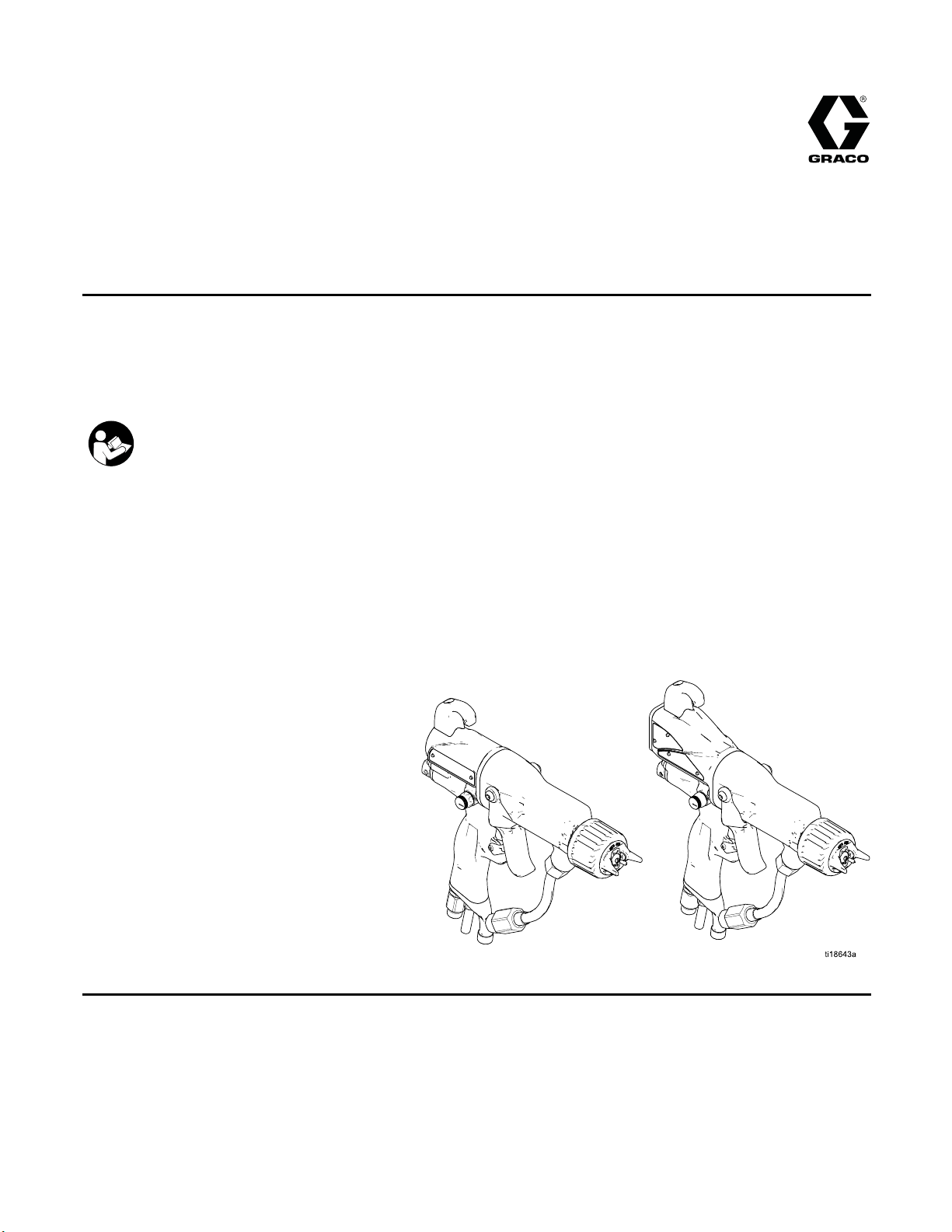
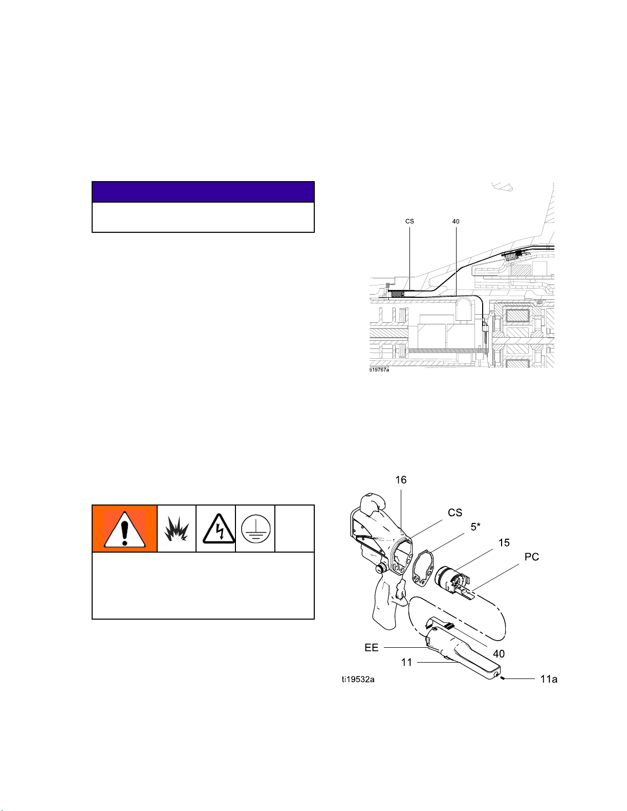
Pro Xp™ Electro
Air-Assisted
For use in Class I, Div. I Hazardous Locations using Group D spray materials.
For use in Group II, Zone 1 Explosive Atmosphere Locations using Group IIA spray materials. For
professional use only.
Important Safety Instructions
Read all warnings and instructions in this manual. Save these
instructions.
3000 psi (
Fluid Wor
100 psi (
Air Work
21 MPa, 210 bar) Maximum
king Pressure
0.7 MPa, 7 bar) Maximum
ing Pressure
Spray Gun
static
3A2495C
EN
See pag
and app
e 3 for model part numbers
roval information.
PROVEN QUALITY. LEADING TECHNOLOGY.
Page 2

Contents
Models............................................................... 3
Warnings ........................................................... 4
Gun Overview .................................................... 7
How the Electrostatic AA Spray Gun
Works ............................................ 7
Controls, Indicators, and Components ........... 8
Smart Guns ................................................. 9
Installation.......................................................... 15
Warning Sign............................................... 15
Ventilate the Spray Booth............................. 15
Air Supply Line ............................................ 16
Fluid Supply Line ......................................... 16
Gun Setup.......................................................... 18
Gun Setup Checklist .................................... 18
Grounding ................................................... 21
Check Gun Electrical Grounding ................... 25
Check Fluid Resistivity ................................. 26
Check Fluid Viscosity ................................... 26
Flush Before Using Equipment...................... 26
Operation........................................................... 27
Pressure Relief Procedure............................ 27
Startup ........................................................ 27
Shutdown.................................................... 27
Maintenance ...................................................... 28
Flushing ...................................................... 28
Clean the Gun Daily..................................... 29
Daily System Care ....................................... 31
Electrical Tests................................................... 32
Test Gun Resistance.................................... 32
Test Power Supply Resistance ..................... 33
Test Gun Barrel Resistance .......................... 34
Troubleshooting.................................................. 35
Spray Pattern Troubleshooting...................... 35
Gun Operation Troubleshooting .................... 36
Electrical Troubleshooting ............................ 37
air................................................................ 39
Rep
pare the Gun for Service ......................... 39
Pre
Cap, Spray Tip, and Fluid Seat Housing
Air
placement.................................. 40
Re
ectrode Replacement ................................ 41
El
Fluid Tube Rem
Fluid Filter R
Gun Barrel Rem
Gun Barrel In
Fluid Needle
Power Supply
Alternator
Fan Air Adju
Atomizing A
ES On-Off V
Air Valve R
Smart Modu
Air Swivel
Parts.................................................................. 54
Standard Air-Assisted Spray Gun
Smart Air-Assisted Spray Gun
Alternator Assembly ..................................... 58
ES On-Off Valve Assembly........................... 59
Fan Air Valve Assembly ............................... 60
Air Cap Assembly ........................................ 61
Smart Module Assembly............................... 61
Spray Tip Selection Chart....................................62
AEM Fine Finish Spray Tips.......................... 62
AEF Fine Finish Pre-Orifice Spray
r Kits, Related Manuals, and
Repai
Acces
Gun Ac
Syste
Test E
Hose
Oper
Dimensions ........................................................ 66
Technical Data ...................................................67
co Pro Xp Warranty....................................... 68
Gra
cessories.......................................... 64
m Accessories..................................... 64
quipment ........................................... 64
s ......................................................... 65
ator Accessories................................... 65
oval and Replacement........... 42
eplacement............................... 42
oval..................................... 43
stallation.................................. 43
Replacement............................ 44
Removal and
Replacement
Removal and Replacement ........... 46
stment Valve Repair .................. 48
ir Adjustment Valve
Repair............................................ 49
alve Repair ............................... 50
epair........................................... 51
le Replacement.......................... 52
and Exhaust Valve
Replaceme
Assembly....................................... 54
Assembly....................................... 56
Tips ............................................... 63
sories .......................................... 64
.................................. 45
nt.................................. 53
2
3A2495C
Page 3
Models
Models
Part No. kV
H60T10 60
H60M10 60
H85T10 85
H85M10 85
Smart Display Standard Display
✔
✔
✔
✔
II 2 G
EEx 0.24 mJ T6
FM12ATEX0068
EN 50050
Ta 0°C – 50°C
3A2495C 3
Page 4

Warnings
Warnings
The following
exclamation p
risks. When th
Warnings. Pr
the body of th
warnings are for the setup, use, grounding, maintenance and repair of this equipment. The
oint symbol alerts you to a general warning and the hazard symbol refers to procedure-specific
ese symbols appear in the body of this manual or on warning labels, refer backtothese
oduct-specific hazard symbols and warnings not covered in this section may appear throughout
is manual where applicable.
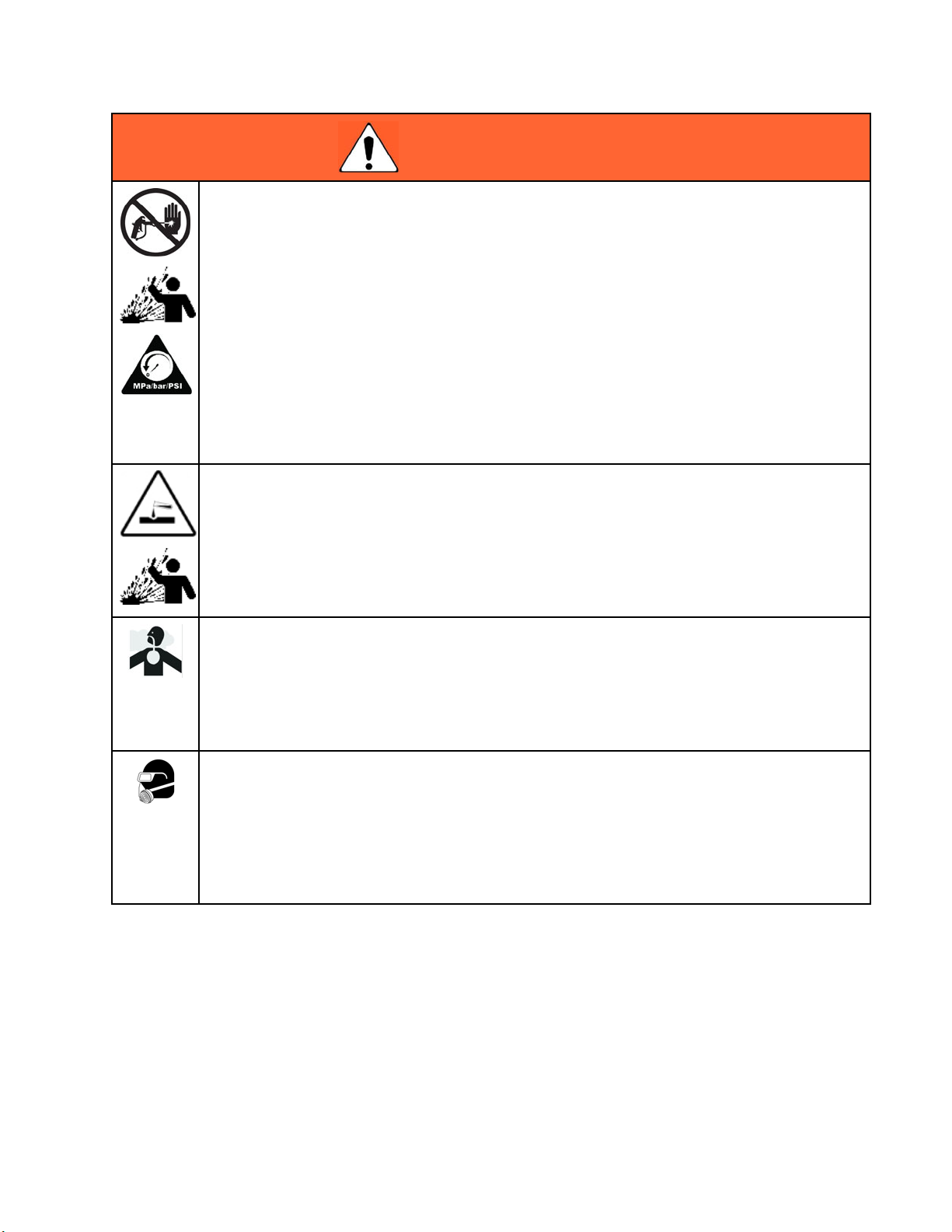
WARNING
FIRE, EXPL
Flammable fumes, such as solvent and paint fumes, in work area can ignite or explode. To help
prevent fire, explosion, and electric shock:
• Electrostatic equipment must be used only by trained, qualified personnel who understand
the requirements of this manual.
• Ground all equipment, personnel, object being sprayed, and conductive objects in or close to
spray area. Resistance must not exceed 1 megohm. See Grounding instructions.
•Onlyuseg
• Do not use pail liners unless they are conductive and grounded.
• Stop operation immediately if static sparking occurs or you feel a shock. Do not use
equipment until you identify and correct the problem.
• Check gu
• Use and clean equipment only in well ventilated area.
• Interlock the gun air supply to prevent operation unless ventilating fansareon.
• Use cle
• To clean the exterior of the equipment, cleaning solvents must have a flash point at least
5°C above ambient temperature.
• Always turn the electrostatics off when flushing, cleaning or servicing equipment.
• Elimi
plast
• Do not plug or unplug power cords or turn lights on or off when flammable fumes are present.
• Keep spray area free of debris, including solvent, rags and gasoline.
•Keep
OSION, AND ELECTRIC SHOCK HAZARD
rounded Graco conductive air supply hoses.
n resistance, hose resistance, and electrical grounding daily.
aning solvents with highest possible flash point when flushing or cleaning equipment.
nate all ignition sources; such as pilot lights, cigarettes, portable electric lamps, and
ic drop cloths (potential static arc).
a working fire extinguisher in the work area.
4
3A2495C
Page 5
Warnings
WARNING
SKIN INJECTION HAZARD
High-pressure fluid from gun, hose leaks, or ruptured components will pierce skin. This may
look like just a cut, but it is a serious injury that can result in amputation. Get immediate surgical
treatment.
• Do not spray w
• Engage trigger lock when not spraying.
• Do not point gun at anyone or at any part of the body.
•Donotputyo
• Do not stop or deflect leaks with your hand, body, glove, or rag.
• Follow the Pressure Relief Procedure when you stop spraying and before cleaning, checking,
or servicing equipment.
• Tighten al
• Check hoses and couplings daily. Replace worn or damaged parts immediately.
PLASTIC PARTS CLEANING SOLVENT HAZARD
Many solvents can degrade plastic parts and cause them to fail, which could cause serious
injury or property damage.
• Use only compatible water-based solvents to clean plastic structural or pressure-containing
parts.
•SeeTechnical Data in this and all other equipment instruction manuals. Read fluid and
solvent manufacturer’s MSDSs and recommendations.
TOXIC F
Toxic fl
inhale
• Read MSDSs to know the specific hazards of the fluids you are using.
•Store
LUID OR FUMES
uids or fumes can cause serious injury or death if splashed in the eyes or on skin,
d, or swallowed.
hazardous fluid in approved containers, and dispose of it according to applicable
lines.
guide
ithout tip guard and trigger guard installed.
ur hand over the spray tip.
l fluid connections before operating the equipment.
PERSONAL PROTECTIVE EQUIPMENT
Wear appropriate protective equipment when in the work area to help prevent serious injury,
including eye injury, hearing loss, inhalation of toxic fumes, and burns. This protective
equipment includes but is not limited to:
ective eyewear, and hearing protection.
•Prot
• Respirators, protective clothing, and gloves as recommended by the fluid and solvent
manufacturer.
3A2495C 5
Page 6
Warnings
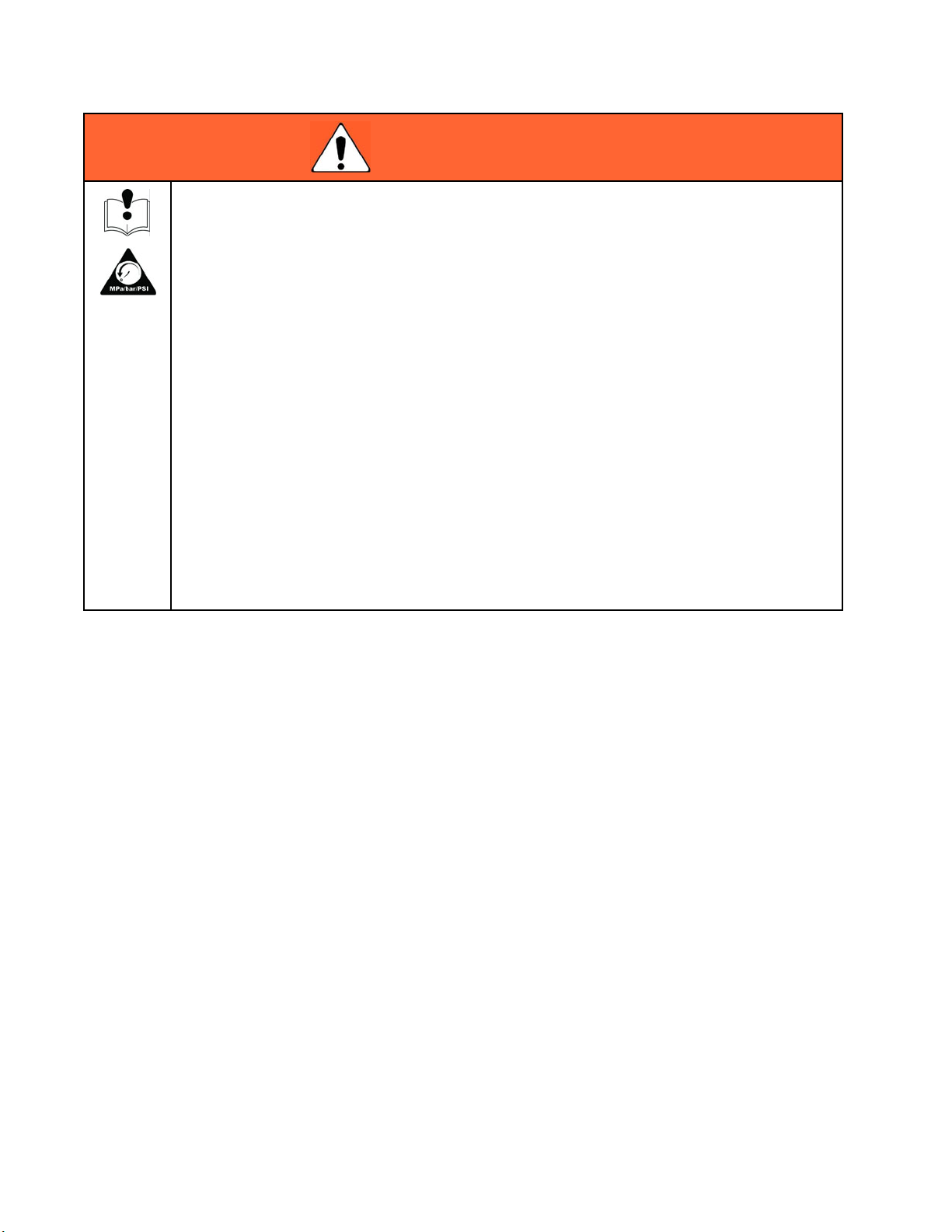
WARNING
EQUIPMENT MISUSE HAZARD
Misuse can cause death or serious injury.
• Do not operat
• Do not exceed the maximum working pressure or temperature rating of the lowest rated
system component. See Technical Data in all equipment manuals.
• Use fluids and solvents that are compatible with equipment wetted parts. See Technical Data
in all equipment manuals. Read fluid and solvent manufacturer’s warnings. For complete
information about your material, request MSDS from distributor or retailer.
• Do not leave
• Turn off all equipment and follow the Pressure Relief Procedure when equipment is not in use.
• Check equipment daily. Repair or replace worn or damaged parts immediately with genuine
manufacturer’s replacement parts only.
• Do not alte
and create
• Make sure all equipment is rated and approved for the environment in which youareusingit.
• Use equipment only for its intended purpose. Call your distributor for information.
• Route hos
• Do not kink or over bend hoses or use hoses to pull equipment.
• Keep children and animals away from work area.
•Complyw
e the unit when fatigued or under the influence of drugs or alcohol.
the work area while equipment is energized or under pressure.
r or modify equipment. Alterations or modifications may void agency approvals
safety hazards.
es and cables away from traffic areas, sharp edges, moving parts, and hot surfaces.
ith all applicable safety regulations.
6 3A2495C
Page 7
Gun Overview
Gun Overview
How the Electr
ostatic AA Spray Gun
Works
This is not an air spray gun. To help prevent
serious injury from pressurized fluid, such as skin
injection, and splashing fluid, read and follow the
Skin Injection Hazard Warnings on page 5.
The air-assisted spray gun combines airless and
air spraying concepts. The spray tip atomizes
and shapes the fluid into a fan pattern, as does
a conventional airless spray tip. Air from the air
cap further atomizes the fluid and completes the
atomization of the fluid tails to produce a uniform
pattern.
As the gun is triggered, part of the regulated air
operates the alternator turbine and the rest of the
air helps atomize the fluid being sprayed. The
alternator ge
the power car
gun’s electr
The fluid is electrostatically charged as it passes
the electrode. The charged fluid is attracted to the
grounded workpiece, wrapping around and evenly
coating all surfaces.
The regulated air that is directed to the air cap can
be further controlled using the gun’s atomizing air
adjustment valve. This valve can be used to restrict
air flow to the air cap while maintaining sufficient air
flow to the alternator. The atomizing air adjustment
valve does not control pattern width. To change
patternwidth,useanewtipsize,orusethefan
adjustment to narrow the pattern width.
Thehighw
the power
NOTE: For airless atomization, if desired, turn the
gun’s atomizing air adjustment valve completely off.
Closing this valve does not affect alternator operation.
nerates power, which is converted by
tridge to supply high voltage to the
ode.
orking fluid pressure of this gun provides
needed to atomize higher solids materials.
3A2495C
7
Page 8
Gun Overview
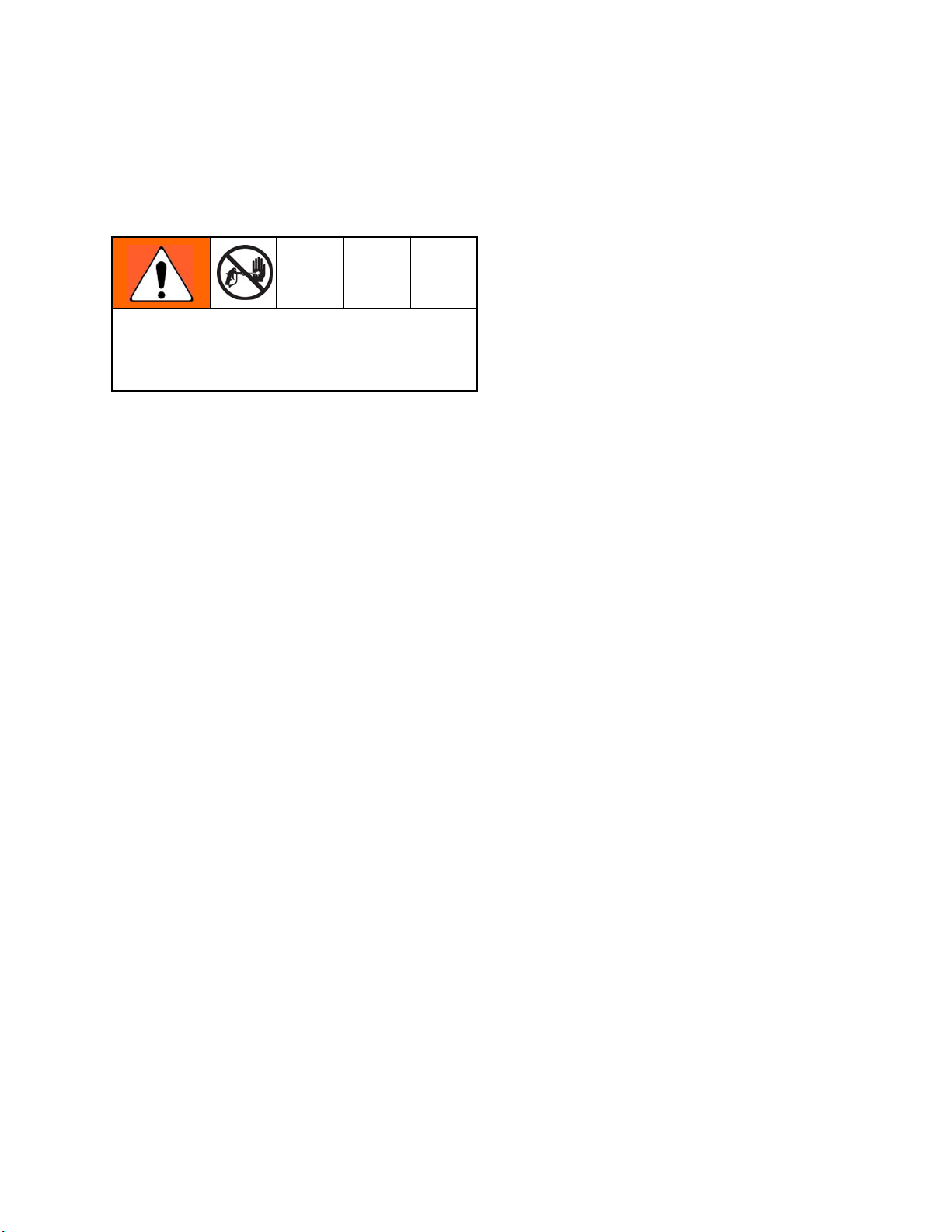
Controls, Ind
The electrostatic gun includes the following
controls, indicators, and components (see Fig.
1). For information on Smart guns, also see
Smart Guns, page 9 .
Item Description Purpose
A
B Fluid Inlet
C
D
EElectrode
FFanAir
Air Swivel
Inlet
Turbine Air
Exhaust
Air Cap/Tip
Guard and
Spray Tip
Adjustment
Valve
icators, and Components
1/4 npsm(m) left-hand
thread, for Graco grounded
air supply hose.
1/4 npsm(m
supply hos
Barbed fitting, for supplied
exhaust tube.
See Spray Tip Selection
Chart, page 62, for avail-
able sizes.
Supplie
charge
Adjusts fan size and shape.
Canbeusedtodecrease
pattern width.
), for fluid
e.
s electrostatic
to the fluid.
Item Description Purpose
G
H
J
K
L Inline F
Atomizing Air
Adjustment
Valve
Trigger Safety
Lock
ES On-Off
Valve
ES Indicator (standard
gun only; for
Smart gun indicator, see
Operating
Mode, page
9 )
luid
Filter
Adjusts atomi
Locks trigge
gun from spra
Turns elect
or OFF (O).
Lit when ES is ON (I).
Color indicates alternator
frequency. See the LED
indicator table in the Gun
Setup Checklist, page 18.
Provides final filtration of
fluid. Located inside fluid
tube fitting.
zing air flow.
rtoprevent
ying.
rostatics ON (I)
Figure 1 Gun Overview
8 3A2495C
Page 9
Smart Guns
Gun Overview
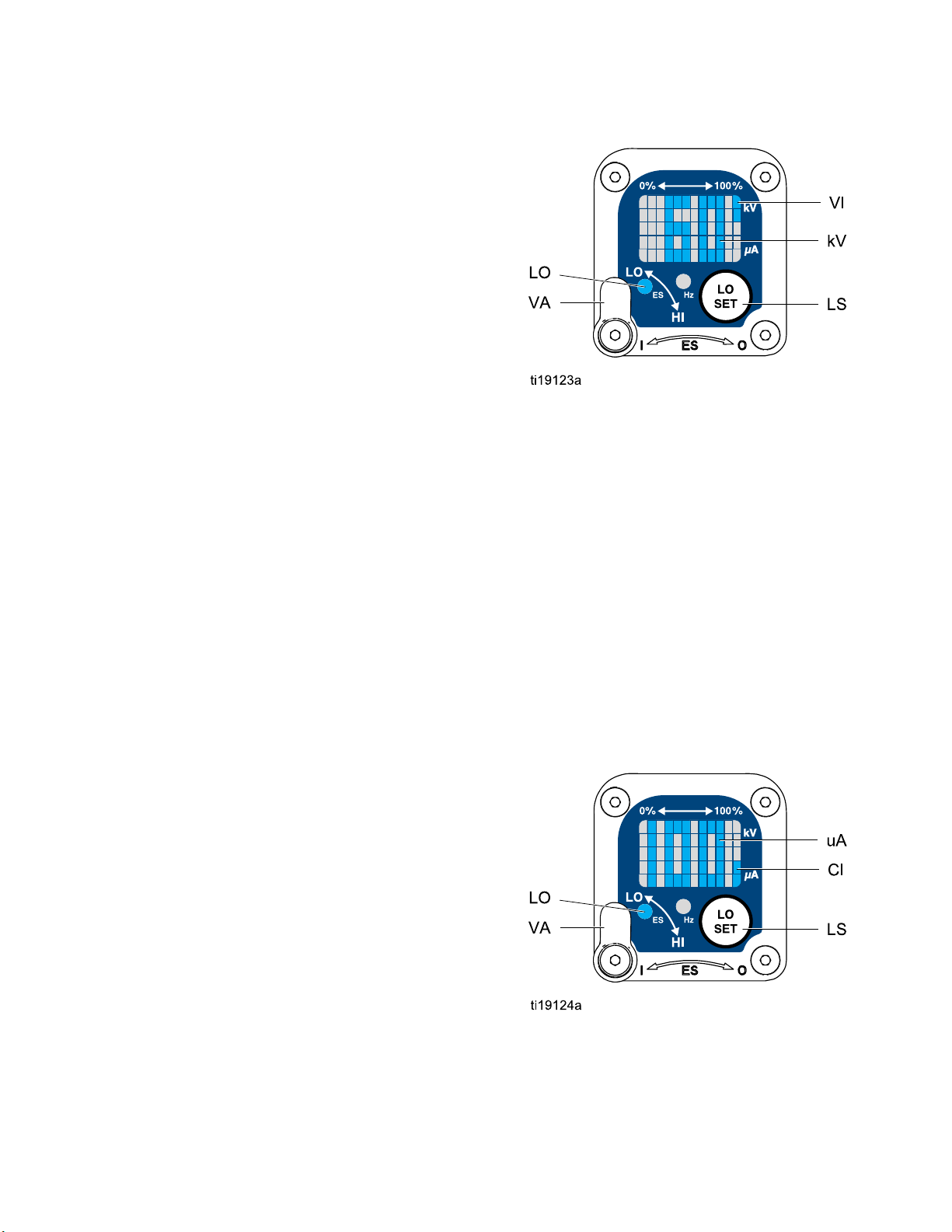
The Smart Gun module displays spraying voltage,
current, alternator speed, and the voltage setting (low
or high). It also allows the user to change to a lower
spraying voltage. The module has two modes:
• Operating Mo
• Diagnostic M
Operating M
de
ode
ode
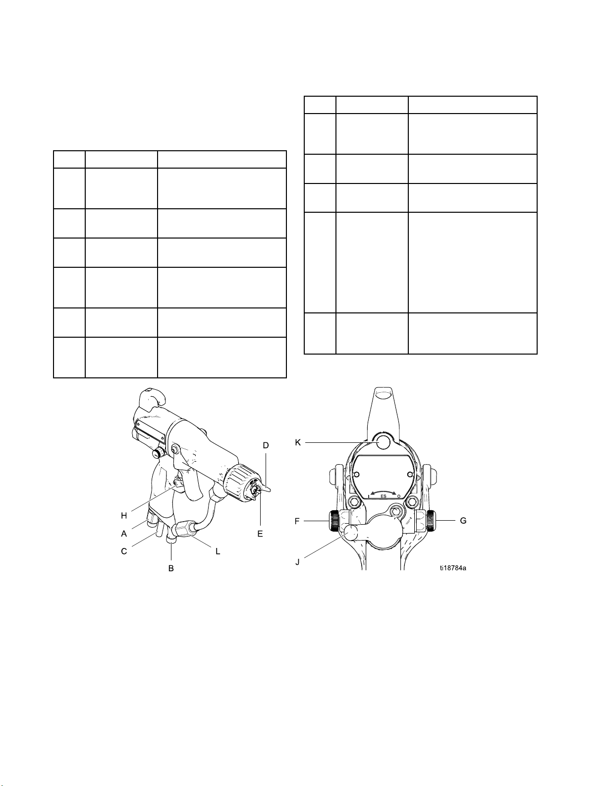
Bar Graph
See Fig. 2,
Mode displ
display u
kiloVolt
(uA). The
value.
If the uA bar graph LEDs are blue, the gun is ready
to spray. If the LEDs are yellow or red, the current is
too high. The fluid may be too conductive, or see
Electrical Troubleshooting, page 37 for other possible
causes.
and Table 1 on page 11. The Operating
ays gun data during normal spraying. The
ses a bar graph to show the voltage level in
s (kV) and the current level in microAmperes
bar graph range is from 0 to 100% for each
Voltage Adjustment Switch
The voltage adjustment switch (VA) allows the
operator to change from low to high voltage.
• The high volt
maximum volt
•Thelowvolt
when the swi
voltage set
Adjusting t
NOTE: If the Error display appears, the Smart module
has lost communication with the power supply. See
Error Display, page 10, for further information.
age setting is determined by the
age of the gun and is not adjustable.
age indicator (LO) lights
tch is set to LO. The low
ting is user adjustable. See
he Low Voltage Setting, page 10.
Hz Indicator
The Hz indicator functions the same as the ES
indicator on standard guns. The indicator lights to
show the alternator speed status, and has three
colors:
• Green indicates the alternator speed is correct.
• If the indicator changes to amber after 1 second,
increase the air pressure.
• If the indicator changes to red after 1 second,
reduce the air pressure.
Figure2 SmartGunModuleinOperatingMode
3A2495C 9
Page 10
Gun Overview
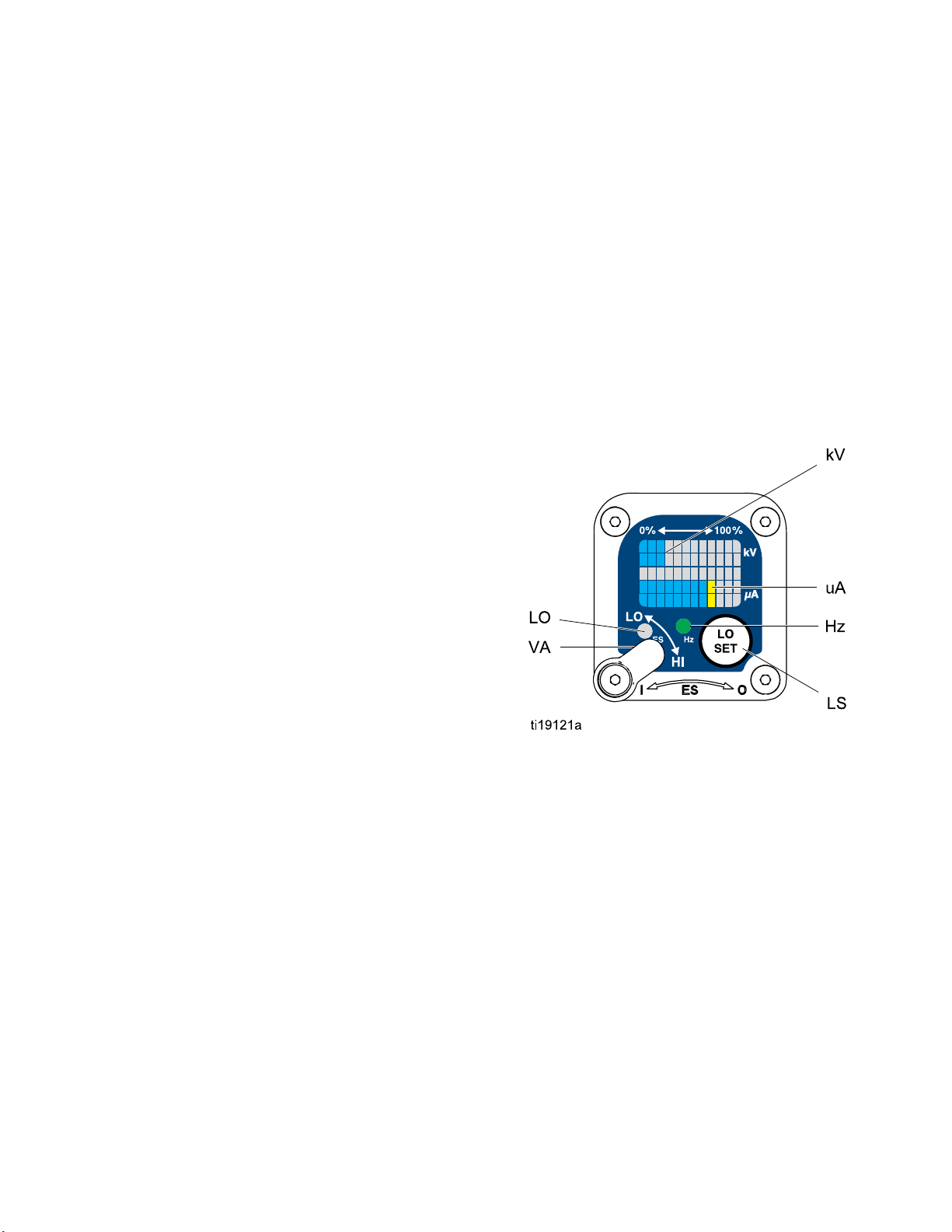
Error Display
If the Smart module loses communication with
the power supply, the Error display appears, the
Hz indicator turns red, and the Smart module is
disabled. See Fig. 3, and Table 1 on page 11.
This can occur in Operating Mode or Diagnostic
Mode. See Electrical Troubleshooting, page 37.
Communication must be restored to make the Smart
module functional.
NOTE: It takes 8 seconds for the Error display to
appear. If the gun has been disassembled, wait 8
seconds before spraying to ensure that an Error
condition has not occurred.
NOTE: If there is no power to the gun, the Error
display will not appear.
for your gun. Continue pressing the button until you
reach the desired setting.
NOTE: After 2 s
return to the O
NOTE: The low voltage setting may be locked. See
Lock Symbol, page 10.
Figure 4 Low Voltage Setting Screen (Unlocked)
econds of inactivity the display will
perating Screen.
Lock Symbol
Figure 3 Error Display
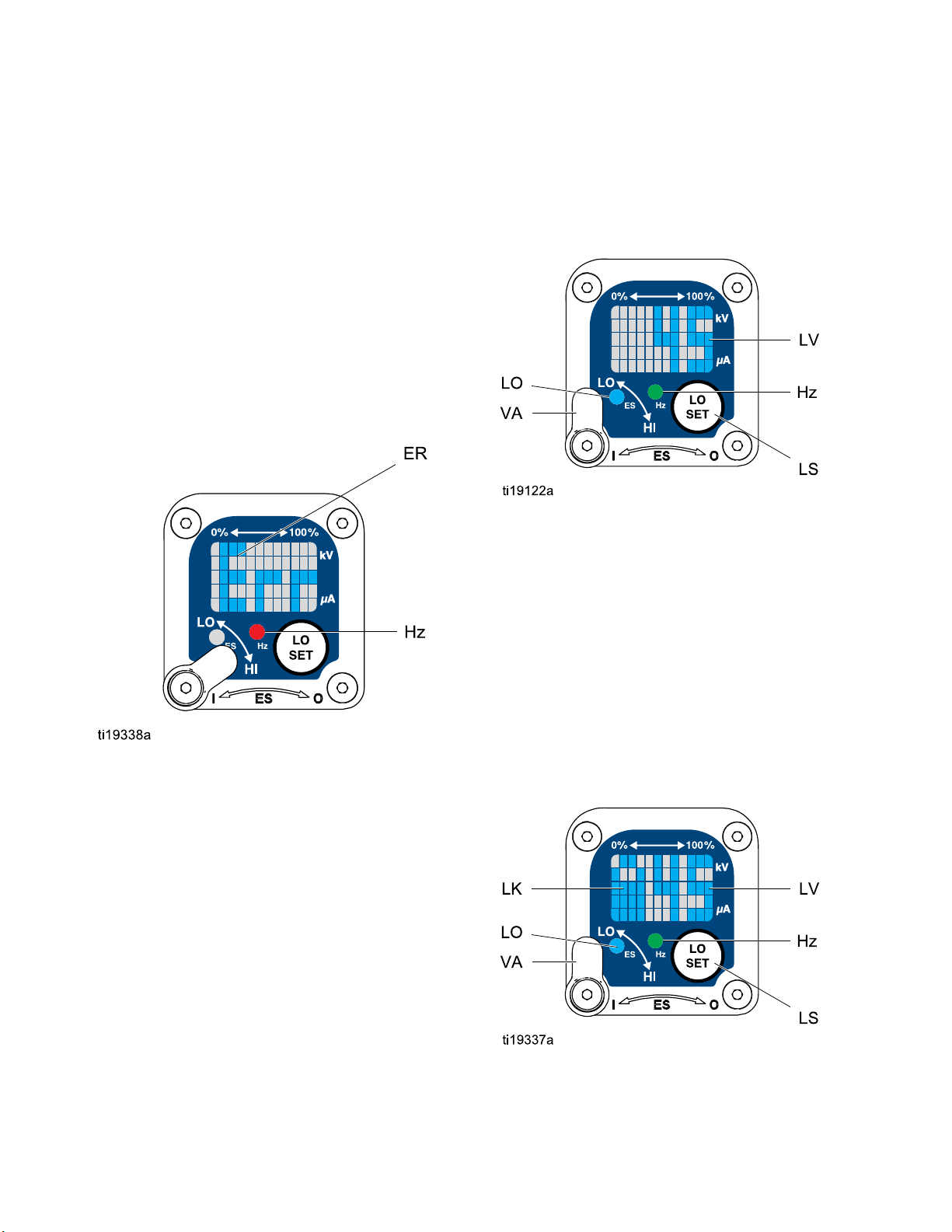
Adjusting the Low Voltage Setting
The low voltage setting is user adjustable. To access
the low voltage setting screen when in Operating
Mode, press the LO SET button (LS) momentarily.
The screen will display the current low voltage
setting. SeeFig. 4,andTable1onpage11. The
possible ranges are:
• 85 kV guns: 40–85 kV
• 60 kV guns: 30–60 kV
t the Voltage Adjustment switch (VA) to LO. Press
Se
e LO SET button repeatedly to increase the setting
th
n increments of 5. When the display reaches the
i
aximum setting it will return to the minimum setting
m
The low voltage setting may be locked. When locked,
an image (LK) appears on the screen. See Fig. 5,
and Table 1 on page 11.
• When in HI mode, the low voltage setting is always
locked. The lock symbol will appear when the LO
SET button is pressed.
• In LO mode, the lock symbol will only
appear if the lock is enabled. See
Low Voltage Lock Screen, page 14,tolock
or unlock the low voltage setting.
gure 5 Low Voltage Setting Screen (Locked)
Fi
10 3A2495C
Page 11

Table 1 . Key for Figs. 2–9.
Item Description Purpose
Gun Overview
VA
LO
kV
uA
LS LO SET bu
Voltage Adjustment Switch
Low Voltage Mode Indicator
Voltage (kV) Display
Current (uA) Display
tton
Two-position
gun voltage to
high setting (
functional i
in Diagnosti
Lights (blue) when the smart gun
is set to Low Voltage.
Displays ac
of the gun, i
Mode, disp
In Diagnos
displayed
Displays actual spraying current
of the gun, in uA. In Operating
Mode, display is a bar graph.
In Diagnostic Mode, current is
displayed as a number.
Press momentarily to enter the
Low Voltage Setting screen.
Press an
seconds
Mode.
switch sets smart
low setting (LO) or
HI). This switch is
n Operating Mode and
c Mode.
tual spraying voltage
n kV. In Operating
lay is a bar graph.
tic Mode, voltage is
as a number.
d hold for approximately 5
to enter or exit Diagnostic
LV Low V
LK Low Voltage Locked
oltage Display
While in Diagnostic Mode, press
momentarily to advance through
screens.
While on the Low Voltage Lock
Screen (in Diagnostic Mode),
press and hold to turn the lock on
or off.
lays the low voltage setting
Disp
umber. The setting can be
as a n
ged. See Fig. 4.
chan
Appears if the low voltage setting
is locked. See Fig. 5 and Fig. 9.
3A2495C
11
Page 12

Gun Overview
Item Description Purpose
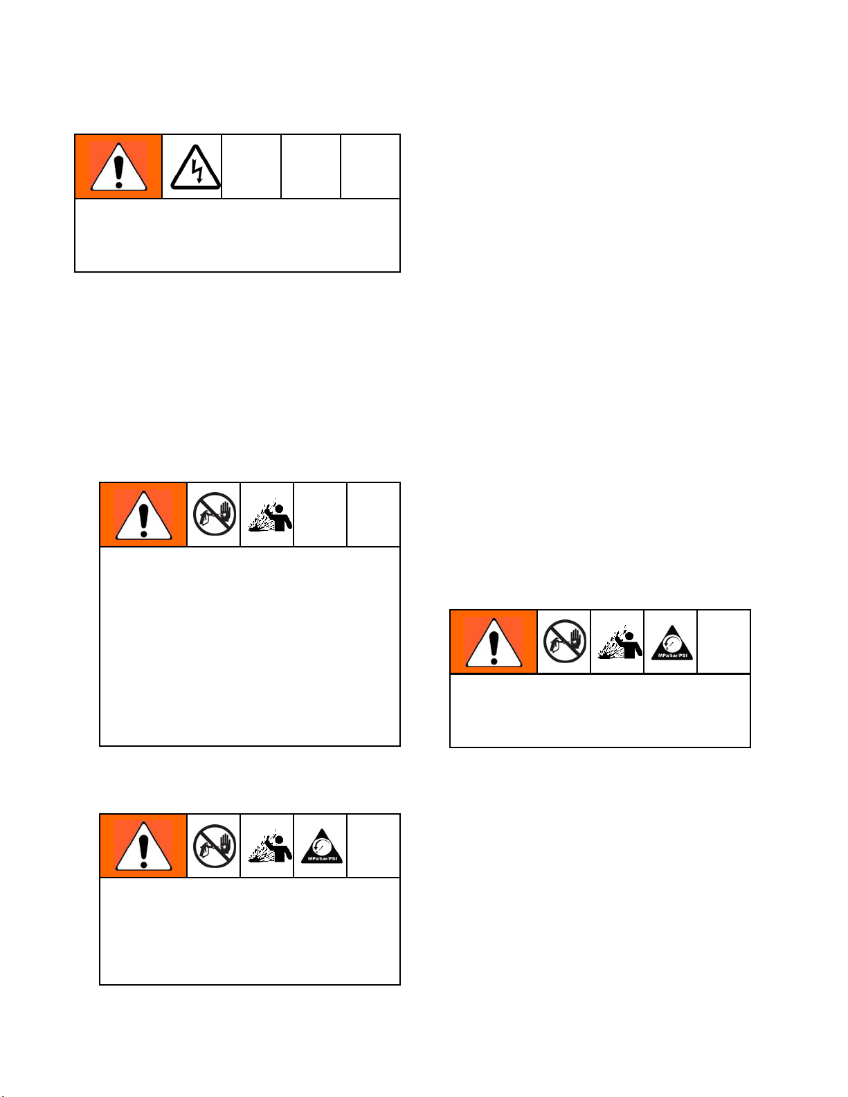
LD Lo Display Appears on the Low Voltage Lock
Screen. See Fig. 9.
ER Error Display
VI Voltage Indicator In Diagnostic Mode, the two top
CI Current Ind
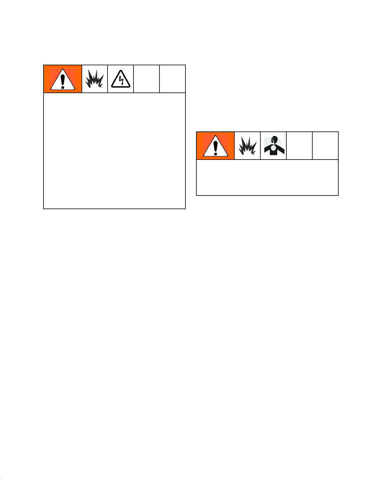
AS Alternator Speed Display
Hz
Alternator Speed Indicator In Operating Mode, indicator color
icator
Appears if the
communicatio
supply. See F
right LEDs of the screen light,
indicating that the value displayed
is in kV. See Fig. 6.
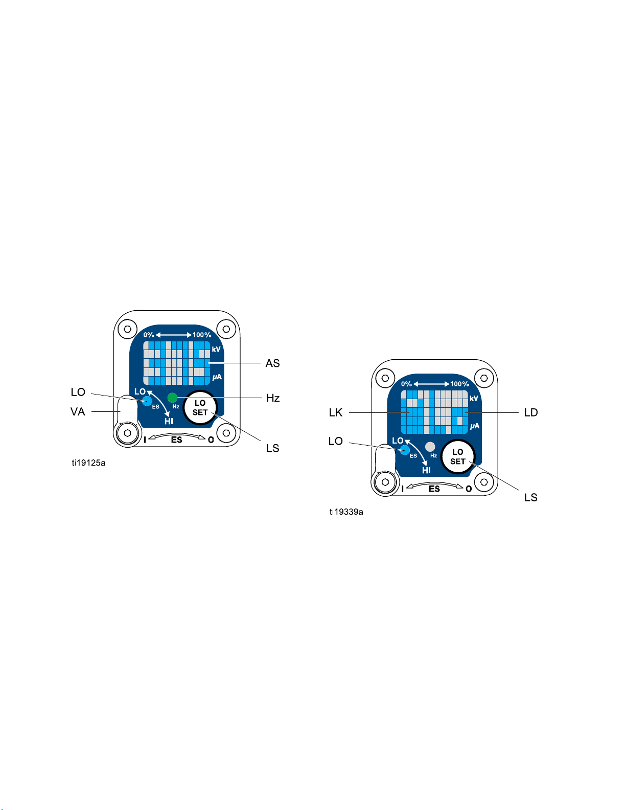
In Diagnostic Mode, the two
bottom right LEDs of the screen
light, indicating that the value
displayedisinuA.SeeFig. 7.
In Diagnos
displaye
8.
varies to show the alternator
speed status:
• green in
speed is
•Ifthei
after 1
speed i
Smart module loses
nwiththepower
ig. 3.
tic Mode, Hz level is
d as a number. See Fig.
dicates the alternator
at the correct level.
ndicator changes to amber
second, the alternator
stoolow.
•Ifthei
In Diagnostic Mode, the indicator
is green when in the Alternator
Speed (Hertz) screen.
ndicator changes to red
1 second, the alternator
after
is too high. The indicator
speed
lsoturnrediftheError
will a
ay appears.
displ
2
1
3A2495C
Page 13
Diagnostic Mode
Diagnostic Mode includes four screens which display
gun data:
Gun Overview
• Voltage (kilo
• Current (mic
• Alternator S
• Low Voltage L
NOTE: You must be in Operating Mode to adjust the
low voltage setting; the setting is not adjustable in
Diagnostic Mode. However, the voltage adjustment
switch (VA) can be set to HI or LO in Operating Mode
and in Diagnostic Mode.
To enter Diagnostic Mode, press and hold the LO SET
(LS) button for approximately 5 seconds. The display
will go to the Voltage (kiloVolts) Screen, page 13.
To advanc
button ag
To exit Diagnostic Mode, press and hold the LO SET
button for approximately 5 seconds. The screen will
return to Operating Mode.
NOTE: If the gun is detriggered while in Diagnostic
Mode,thelastscreenviewedwillbedisplayedwhen
the gun is retriggered.
NOTE: D
from th
Low Vol
Volta
e Low Voltage Lock Screen. See
ge (kiloVolts) Screen
Volts) Screen
roAmperes) Screen
peed (Hertz) Screen
ock Screen
e to the next screen, press the LO SET
ain.
iagnostic Mode cannot be exited
tage Lock Screen, page 14 for details.
Figure 6 Voltage (kiloVolts) Screen
Current (microAmperes) Screen
The Current (microAmperes) Screen is the second
screen in the Diagnostic Mode. See Fig. 7, and Table
1 on page 11. To enter this screen, press the LO
SET button while in the Voltage (kiloVolts) Screen.
This screen displays the spraying current of the gun
as a number (uA), rounded to the nearest 5 uA. The
two bottom right LEDs (CI) of the display panel light,
indicating that the Current (microAmperes) Screen
is displayed. The display is a readout and cannot
be changed.
Press the LO SET button to advance to the
Alternator Speed (Hertz) Screen, page 14.Press
and hold for approximately 5 seconds to return to
Operating Mode.
The Vo
appea
and T
and h
seco
This screen displays the spraying voltage of the
gun as a number (kV), rounded to the nearest 5 kV.
The two top right LEDs (VI) of the display panel
light, indicating that the Voltage (kiloVolts) Screen
is displayed. The display is a readout and cannot
be changed.
Press the LO SET button to advance to the
Current (microAmperes) Screen, page 13.Press
and hold for approximately 5 seconds to return to
Operating Mode.
ltage (kiloVolts) Screen is the first screen to
r after entering Diagnostic Mode. See Fig. 6,
able 1 on page 11. To enter this screen, press
old the LO SET button for approximately 5
nds while in the Operating Mode.
Figure 7 Current (microAmperes) Screen
3A2495C 13
Page 14
Gun Overview
Alternator Speed (Hertz) Screen
The Alternator Speed (Hertz) Screen is the third
screen in the Diagnostic Mode. See Fig. 8, and Table
1 on page 11. To enter this screen, press the LO SET
button while in the Current (microAmperes) Screen.
This screen d
number (AS),
display is a r
alternator s
will show 99
The Hz indicator lights green to show that you are
viewing the Alternator Speed (Hertz) Screen.
Press the LO SET button to advance to the
Low Voltage Lock Screen, page 14. Press and hold
for approximately 5 seconds to return to Operating
Mode.
isplays the alternator speed as a 3 digit
rounded to the nearest 10 Hz. The
eadout and cannot be changed. If the
peed is greater than 999 Hz, the display
9.
Low Voltage Lock Screen
The Low Voltage Lock Screen is the fourth screen in
the Diagnostic Mode. See Fig. 9, and Table 1 on
page 11. To enter this screen, press the LO SET
button while in the Alternator Speed (Hertz) Screen.
This screen d
Lock. If the s
appears to th
is unlocked,
To change the lock status, press and hold the
LO SET button until the lock image appears or
disappears. If the lock is set, the image will also
appear on the Low Voltage Setting Screen when in
low voltage mode (see Fig. 4).
NOTE: Diagnostic Mode cannot be exited from this
screen, because pressing and holding the LO SET
button is used to turn the lock on or off. To exit,
press LO SET momentarily to return to the Voltage
(kiloVolts) Screen, then exit Diagnostic Mode from
there.
isplays the status of the Low Voltage
etting is locked, the lock image (LK)
e left of the Lo display (LD). If the setting
the lock image does not appear.
Figure 8 Alternator Speed (Hertz) Screen
4
1
Figure 9 Low Voltage Lock Screen
3A2495C
Page 15
Installation
Installing and servicing this equipment requires
access to parts which may cause electric shock
or other serious injury if work is not performed
properly.
• Do not install or service this equipment unless
you are trained and qualified.
• Be sure your installation complies with local,
state, and national codes for the installation
of electrical apparatus in a Class I, Div. I
Hazardous Location or a Group II, Zone I
Explosive Atmosphere Location.
• Comply with all applicable local, state, and
national fire, electrical, and other safety
regulations.
Fig. 10 shows a typical electrostatic air-assisted
spray system. It is not an actual system design.
For assistance in designing a system to suit your
particular needs, contact your Graco distributor.
Installation
Warning Sign
Mount warning signs in the spray area where they
can easily be seen and read by all operators. An
English Warning Sign is provided with the gun.
Ventilate the Spray Booth
Provide fresh air ventilation to reduce the risk of fire
or explosion caused by the buildup of flammable or
toxic vapors when spraying, flushing, or cleaning
the gun. Do not operate the gun unless ventilation
fans are operating.
Electrically interlock the gun air supply with the
ventilators to prevent gun operation without
ventilating fans operating. Check and follow all local,
state, and national codes regarding air exhaust
velocity requirements.
High velocity air exhaust will decrease the operating
efficiency of the electrostatic system. Air exhaust
velocity of 100 ft/min (31 linear meters/minute) should
be sufficient.
3A2495C 15
Page 16
Installation
Air Supply Lin
To reduce the risk of electric shock, the air supply
hose must be electrically connected to a true earth
ground. Use only Graco Grounded Air Supply
Hose.
1. See Fig. 10. Use the Graco Grounded Air Supply
Hose (AH) to supply air to the gun. The gun air
inlet fitting has a left-hand thread. The air supply
hose ground wire (AG) must be connected to a
true earth ground. Do not connect the air supply
hose to the gun air inlet yet.
2. Install an air line filter/water separator (AF) on the
gunairlinetoensureadry,cleanairsupplytothe
gun. Dirt and moisture can ruin the appearance
of your finished workpiece and can cause the
gun to malfunction.
e
4. Install a blee
air supply lin
required in yo
and relieve a
the pump afte
an additiona
line(MA)toi
5. Install an a
supply line
air trapped
the air reg
d-type air valve (BV) on the pump
e. The bleed-type air valve (BV) is
ur system to shut off air to the pump
ir trapped between the valve and
r the air regulator is shut off. Install
l bleed-type air valve on the main air
solate the accessories for servicing.
ir bleed valve (BV) on each gun air
to shut off air to the gun(s) and relieve
between the valve and the gun after
ulator is shut off.
Fluid Supply Line
1. Blow out t
with solv
with the fl
fluid supp
2. Install
linetoc
he fluid line (FL) with air and flush it
ent. Use solvent which is compatible
uid to be sprayed. Do not connect the
lylinetothegunfluidinletyet.
a fluid pressure regulator (FR) on the fluid
ontrol fluid pressure to the gun.
To reduce the risk of serious injury due to
component rupture, including skin injection,
pump pressure must be limited by the pump air
regulator. Do not rely on the gun fluid regulator
tolimitthefluidpressuretothegun.
The flu
produ
3000 p
Fluid
supp
exce
3. Install bleed-type air regulators (PR, GR) on
the pump and gun air supply lines to control air
pressure to the pump and gun.
Trapped air can cause the pump to cycle
unexpectedly, which can result in serious
injury, including skin injection and splashing
fluid in the eyes or on the skin. Do not operate
the equipment without the bleed-type air valve
(BV) installed.
id supply pump must be prevented from
cing a fluid pressure greater than the
si (21 MPa, 210 bar)
Pressure
ly pressure to a 30:1 ratio pump must not
ed 100 psi (0.7 MPa, 7 bar).
of the gun. For example, the air
Maximum Working
3. Install
4. Thefluiddrainvalve(FD)isrequiredinyour
a fluid filter (FF) near the pump outlet, to
remove
the spr
NOTE: T
additi
To reduce the risk of serious injury, including
skin injection and splashing fluid in the eyes or
on the skin, do not operate equipment without
the fluid drain valve (FD) installed.
system to assist in relieving fluid pressure in the
displacement pump, hose, and gun. Triggering
the gun to relieve pressure may not be sufficient.
Install a drain valve close to the pump's fluid
outlet.
particles and sediment which could clog
ay nozzle.
he gun includes an inline fluid filter for
onal filtration.
16 3A2495C
Page 17
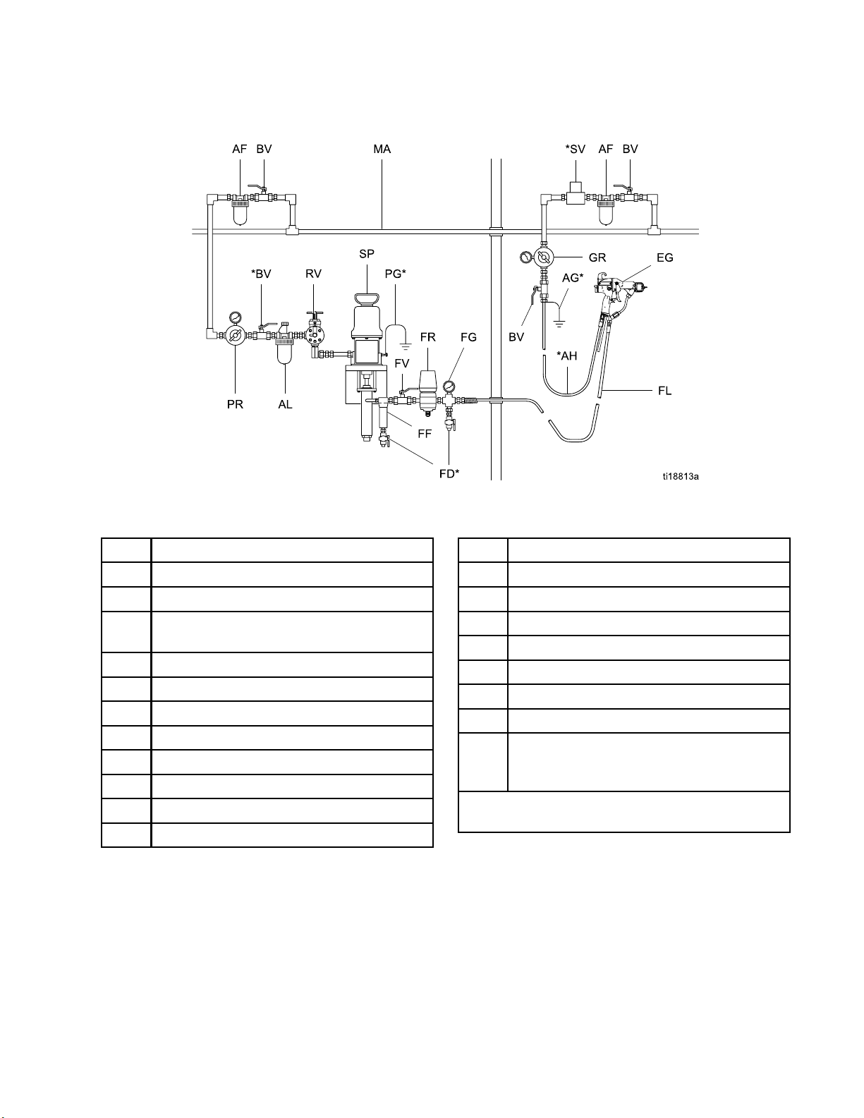
NON-HAZARDOUS AREA HAZARDOUS AREA
Installation
Figure 10 Typical Installation
Typical Installation Key
Item Description
AF
AG* Gun Air Hose Ground Wire
AH* Graco Grounded Air Hose (left-hand
AL Pump Air Line Lubricator
BV* Pump Bleed-Type Air Shutoff Valve
EG Electrostatic Air Spray Gun
FD*
FF Fluid Filter
FG Fluid Pressure Gauge
FL
FR Fluid Pressure Regulator
Air Filter/Water Separator
threads)
Fluid Drain Valve
Fluid Supply Line
Item Description
FV
GR Gun Air Pressure Regulator
MA
PG* Pump Ground Wire
PR Pump Air Pressure Regulator
RV Pump Runaway Valve
SP Supply Pump
SV* Ventilation Fan Interlock Solenoid Valve
* These items are required for safe operation. They
must be purchased separately.
Fluid Shutoff Valve
Main Air Supply Line
NOTE: The solenoid valve is not offered as
a Graco accessory.
3A2495C
17
Page 18
Gun Setup
Gun Setup
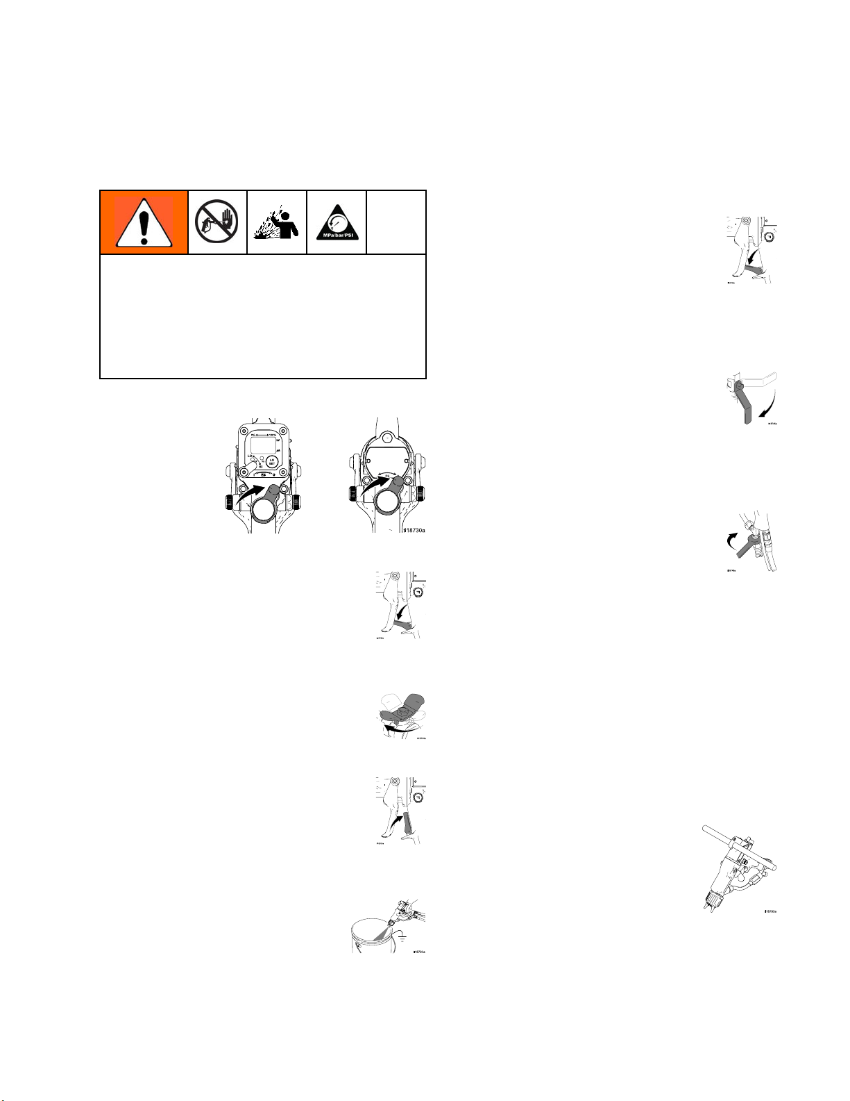
Gun Setup Chec
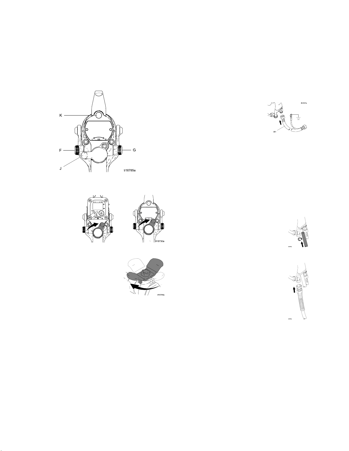
See Fig. 11 to locate the electrostatic gun controls.
Figure 11 Electrostatic Gun Controls
1. Turn OFF (O) the ES On-Off switch (J).
klist
4. Connect the Graco grounded air hose to the gun
air inlet. The gun air inlet fitting has left-hand
threads.
5. Follow all steps under Grounding, page 21.
6. Follow all steps under
Check Gun Electrical Grounding, page 25.
Readingmustbelessthan1megohm.
7. Verify that the material resistivity meets
requirements for electrostatic spray. See
Check Fluid Resistivity, page 26.
8. Connect the exhaust tube and secure with the
clamp provided.
2. Shut off the air bleed valve to the gun.
3. Check gun resistance. See
Test Gun Resistance, page 32.
9. Connect the fluid hose to the gun fluid inlet.
10. Flush if needed. See Flushing, page 28.
18 3A2495C
Page 19
To reduce the risk of a skin injection injury, always follow the
Pressure Relief Procedure, page 27,
before removing or installing the spray tip, air
cap, or tip guard.
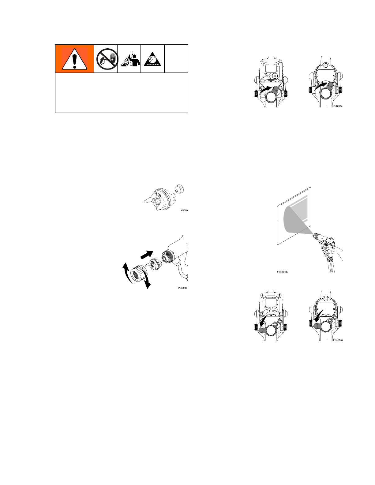
11. The fluid output and pattern width depend
on the size of the spray tip, the fluid
viscosity, and the fluid pressure. Use the
Spray Tip Selection Chart, page 62, as a guide
for selecting the appropriate spray tip for your
application.
12. Align the spray tip tab with the groove in the air
cap. Install the tip.
Gun Setup
15. Check that the ES On-Off switch is OFF (O).
16. Start the pum
(2.8 MPa, 28
17. Spray a test
the center o
in step 21)
increment
particle s
the partic
3000 psi (2
p. Set the fluid regulator to 400 psi
bar).
pattern. Examine the particle size in
f the pattern (tails will be removed
. Increase the pressure in small
s. Spray another pattern. Compare
ize. Continue increasing pressure until
le size remains constant. Do not exceed
1 MPa, 210 bar).
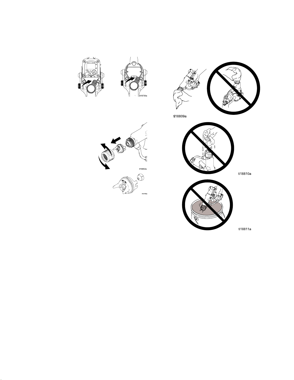
13. Install the air cap and retaining ring. Orientate
the air cap and tighten the retaining ring securely.
14. Close the atomizing air adjustment valve (G) and
the fan air adjustment valve (F).
18. Turn ON (I) the ES On-Off switch.
3A2495C 19
Page 20
Gun Setup
19. Check that the ES indicator (K) [Hz indicator on
Smart guns] is lit. See the following table.
Table 2 . LED Indicator Colors
Indicator
Color
Green
Amber
Red
20. Set the gun air regulator to deliver a minimum
of 45 psi (0.32 MPa, 3.2 bar) at the gun when
triggered, to ensure full spraying voltage. See
the table below.
When spraying, the indicator
should remain green, indicating
sufficient air pressure to the
alternator turbine.
If the indicator changes to amber
after 1 second, the air pressure
is too low. Increase air pressure
until the indicator is green.
If the indi
after 1 se
too high.
until the
Description
cator changes to red
cond, the air pressure is
Decrease air pressure
indicator is green.
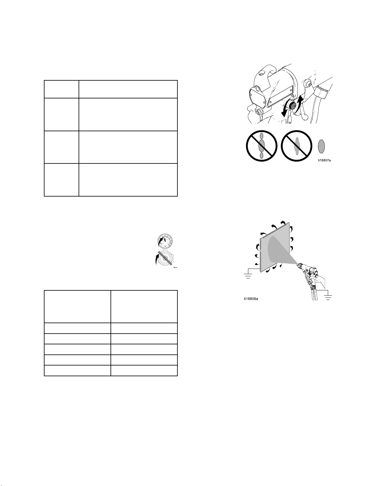
21. Turn the atomizing air adjustment valve
counterclockwise until any tails disappear.
22. If desired atomization is not achieved, change
the tip size. The smaller the tip orifice, the finer
the atomization.
23. Spray a test piece. Examine the edges
for coverage. If wrap is poor, see
Troubleshooting, page 35.
Table 3 . Pressure Drop
Air Hose
Length in ft (m)
(using 5/16 in. [8
mm] diameter hose)
15 (4.6) 52 (0.36, 3.6)
25 (7.6) 57 (0.40, 4.0)
50 (15.3) 68 (0.47, 4.7)
75 (22.9) 80 (0.56, 5.6)
100 (30.5) 90 (0.63, 6.3)
Air Regulator Setting
in psi (MPa, bar)
[with gun triggered]
NOTE: If a narrower pattern is needed occasionally,
open the fan air adjustment valve slightly. (Excessive
fan air flow can cause paint buildup on the air cap.)
20 3A2495C
Page 21
Grounding
Gun Setup
When operating the electrostatic gun, any
ungrounded objects in the spray area (people,
containers, tools, etc.) can become electrically
charged. Improper grounding can result in static
sparking, which can cause a fire, explosion, or
electric shock. Ground all equipment, personnel,
object being sprayed, and conductive objects
in or close to the spray area. Resistance must
not exceed 1 megohm. Follow the grounding
instructions below.
The following are minimum grounding requirements
for a basic electrostatic system (see Figs. 12–15).
Your system may include other equipment or objects
which must be grounded. Check your local electrical
code for detailed grounding instructions. Your system
must be connected to a true earth ground.
•
Pump/fluid source:
by connecting its ground wire to a true earth
ground.
ground the pump/fluid source
•
Object being s
clean and grou
•
All electrically conductive objects or devices in the
spray area:
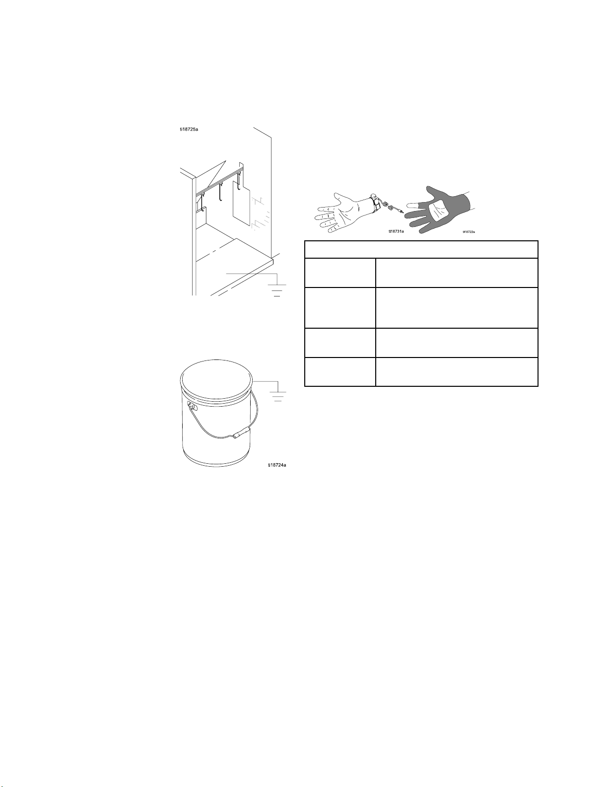
•
Fluid and waste containers:
waste containers in the spray area. Do not use pail
liners unless they are conductive and grounded.
When flushing the spray gun, the container used
to catch the excess fluid must be electrically
conductive and grounded.
prayed:
nded at all times.
must be properly grounded.
keep the workpiece hangers
ground all fluid and
•
Electrostatic Air-Assisted Spray Gun:
the gun by connecting the Graco Grounded
Air Hose to the gun, and connecting the air
hose ground wire to a true earth ground. See
Check Gun Electrical Grounding, page 25.
ground
•
Air compressors:
to the manufacturer's recommendations.
•
All air and fluid lines
Use only grounded hoses with a maximum of 100
feet (30.5 m) combined hose length to ensure
grounding continuity
ground the equipment according
must be properly grounded.
3A2495C
21
Page 22
Gun Setup
The floor of the spray area:
•
conductive and grounded. Do not cover the floor
with cardboard or any non-conductive material
which would interrupt grounding continuity
•
Flammable liquids in the spray area:
in approved, grounded containers. Do not use
plastic containers. Do not store more than the
quantity needed for one shift.
must be electrically
must be kept
•
All persons entering the spray area:
shoes having conductive soles such as leather,
or wear personal grounding straps. Do not
wear shoes with non-conductive soles such as
rubber or plastic. If gloves are necessary, wear
the conductive gloves supplied with the gun. If
non-Graco gloves are worn, cut off fingers or palm
area of gloves to ensure your hand contacts the
grounded gun handle.
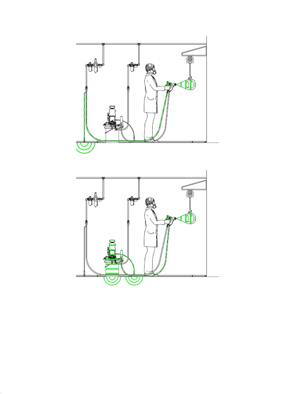
Key to Figs
Fig. 12
Fig. 13
Fig. 14
Fig. 15 Fluid supply line and source must
. 12–15
Operator is grounded through the
gun handle and conductive shoes.
Object being sprayed is grounded
through contact with the hanger
and conveyor system.
Gun is gr
conduct
be grounded.
ounded through the
ive air hose.
must wear
2
2
3A2495C
Page 23
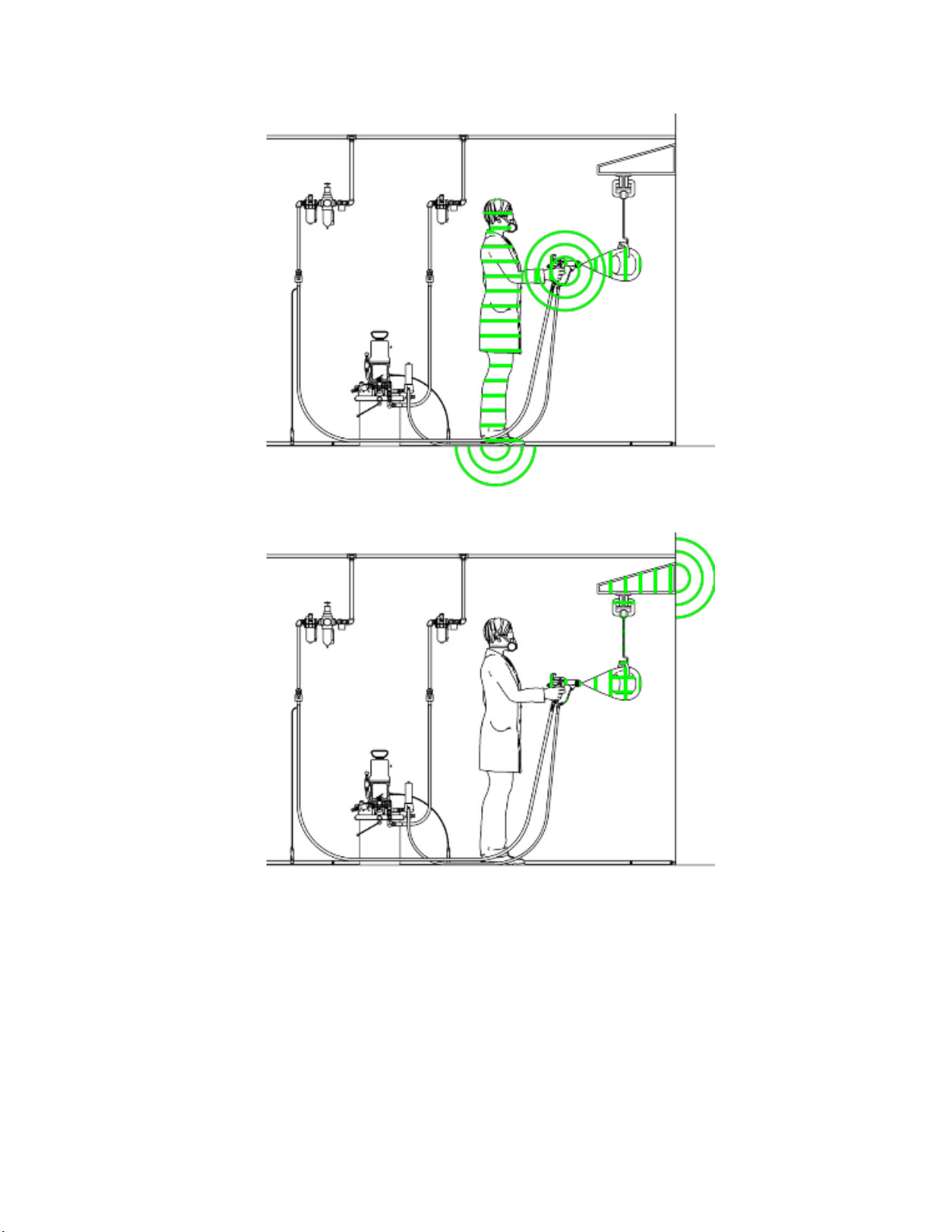
Figure 12 Ground the Operator
Gun Setup
Figure 13 Ground the Object being Sprayed
3A2495C 23
Page 24
Gun Setup
Figure 14 Ground the Gun
Figure 15 Ground the Fluid Supply
4
2
3A2495C
Page 25
Gun Setup
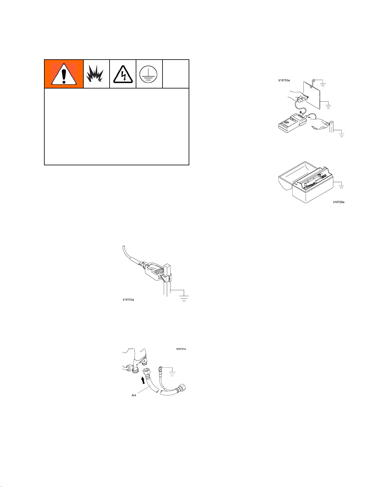
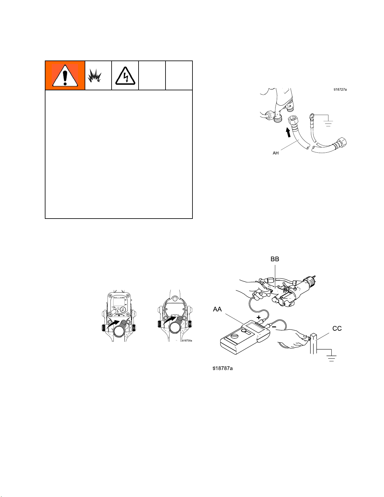
Check Gun Elec
Megohmmeter Part No. 241079 (AA-see Fig.
16) is not approved for use in a hazardous area.
To reduce the risk of sparking, do not use the
megohmmeter to check electrical grounding
unless:
• The gun has been removed from the hazardous
area;
• Or all spraying devices in the hazardous area
are turned off, ventilation fans in the hazardous
area are operating, and there are no flammable
vapors in the area (such as open solvent
containers or fumes from spraying).
Failure to follow this warning could cause fire,
explosion, and electric shock and result in serious
injury and property damage.
Graco Part No. 241079 Megohmmeter is available
as an accessory to check that the gun is properly
grounded.
trical Grounding
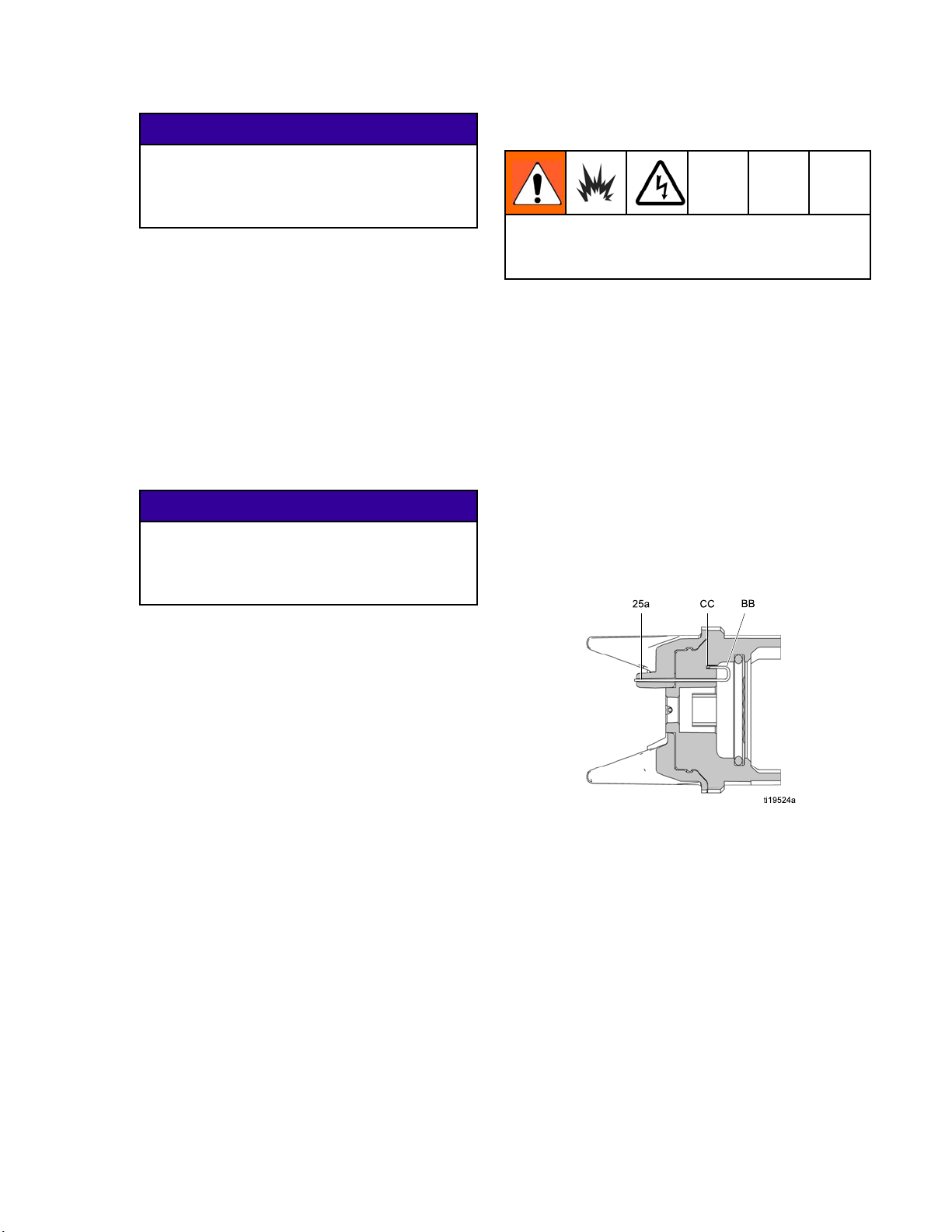
5. Make sure the g
and the hose gr
earth ground.
6. Measure the resistance between the gun handle
(BB) and a true earth ground (CC). Use an
applied voltage of 500 minimum to 1000 volts
maximum. The resistance should not exceed 1
megohm. See Fig. 16.
7. If the resistance is greater than 1 megohm, check
the tightness of the ground connections and be
suretheairhosegroundwireisconnectedtoa
true earth ground. If the resistance is still too
high, replace the air hose.
rounded air hose is connected
ound wire is connected to a true
1. Have a qualified electrician check the electrical
grounding continuity of the spray gun and air
hose.
2. Turn OFF (O) the ES On-Off switch.
3. Turn off the air and fluid supply to the gun. Follow
the Pressure Relief Procedure, page 27.
4. Disconnect the fluid hose.
Figure 16 Check Gun Electrical Grounding
3A2495C 25
Page 26
Gun Setup
Check Fluid Re
To reduce the risk of fire, explosion, or electric
shock, check the fluid resistivity in a non-hazardous
area only. Resistance Meter 722886 and Probe
722860 are not approved for use in a hazardous
area.
Failure to follow this warning could cause fire,
explosion, or electric shock and result in serious
injury and property damage.
Graco Part No. 722886 Resistance Meter and
722860 Probe are available as accessories to check
that the resistivity of the fluid being sprayed meets
the requirements of an electrostatic air-assisted
spray system.
Follow the instructions included with the meter and
probe. Readings of 25 megohms-cm and above
provide the best electrostatic results.
Table 4 . Fluid Resistivity Levels
sistivity
Check Fluid Vi
To check fluid viscosity you will need:
• a viscosity cu
• a stopwatch.
1. Completely submerge the viscosity cup in
the fluid. Lift the cup out quickly, starting the
stopwatch as soon as the cup is completely
removed.
2. Watch the stream of fluid coming from the bottom
of the cup. As soon as there is a break in the
stream, shut off the stopwatch.
3. Record the fluid type, elapsed time, and size of
the viscosity cup.
4. If the viscosity is too high or too low, contact the
material supplier. Adjust as necessary.
scosity
p
Flush Before Using Equipment
The equipment was tested in fluid at the factory. To
avoid contaminating your fluid, flush the equipment
with a compatible solvent before using the equipment.
Megohms-cm
1–5 5–25 25–200 200–2000
Test electrostatic
performance
Good electrostatic
results
Best electrostatic
results
Good electrostatic
results
26 3A2495C
Page 27
Operation
Operation
Pressure Reli
This equipment stays pressurized until pressure
is manually relieved. To help prevent serious
injury from pressurized fluid, such as skin injection,
splashing fluid and moving parts, follow the
Pressure Relief Procedure when you stop spraying
and before cleaning, checking, or servicing the
equipment.
1. Turn OFF (O) the ES On/Off switch.
2. Engage the trigger lock.
ef Procedure
6. Engage the tr
7. Open the pum
container
thepumpdr
to spray ag
8. If the spray tip or hose is completely clogged or
pressure is not fully relieved, slowly loosen the
hose end coupling. Now clear the spray tip or
hose.
igger lock.
pdrainvalve,havingawaste
ready to catch the drainage. Leave
ain valve open until you are ready
ain.
3. Turn off the air bleed valves to the fluid source
and to the gun.
4. Dis
5. Trigger the gun into a grounded metal waste
engage the trigger lock.
container to relieve the fluid pressure.
Startup
Follow all steps under Gun Setup Checklist, page 18.
Shutdown
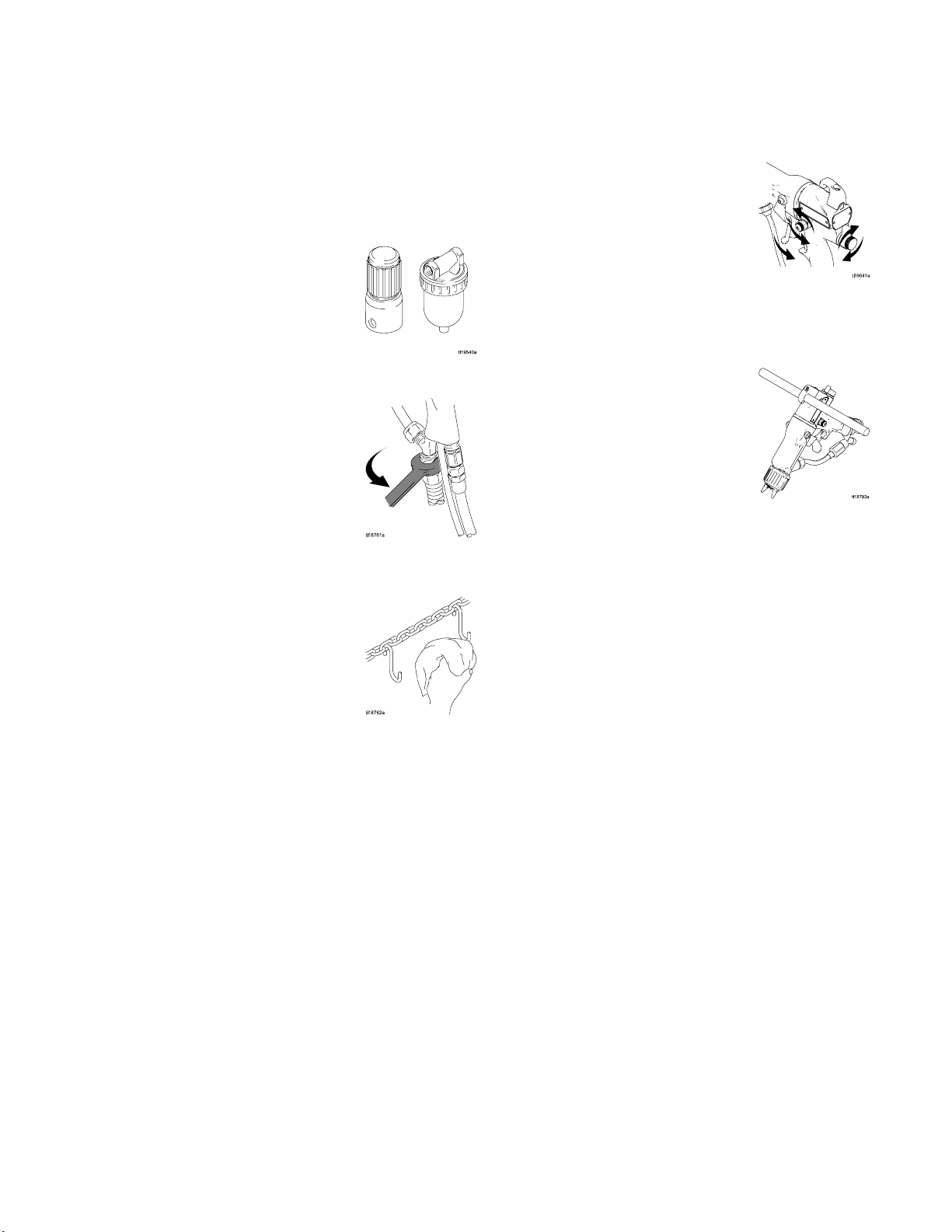
1. Flush the gun. See Flushing, page 28.
2. Follow the Pressure Relief Procedure, page 27.
3. Hang the gun from its hook, with the nozzle
pointing down.
3A2495C
27
Page 28
Maintenance
Maintenance
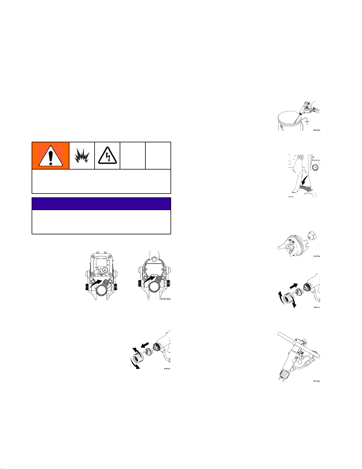
Flushing
•Flushbefore
in the equipm
storing, and
•Flushatthe
connectors
•Flushwitha
being dispe
To reduce the risk of fire, explosion, or electric
shock, turn OFF (O) the ES On-Off switch before
flushing the gun.
changing fluids, before fluid can dry
ent, at the end of the day, before
before repairing equipment.
lowest pressure possible. Check
for leaks and tighten as necessary.
fluid that is compatible with the fluid
nsed and the equipment wetted parts.
NOTICE
Do not use methylene chloride as a flushing or
cleaning solvent with this gun as it will damage
nylon components.
1. Turn OFF (O) the ES On-Off switch.
5. Point the gun
until clean s
6. Follow the Pressure Relief Procedure, page 27.
Engage the trigger lock.
7. Shut off or disconnect the solvent line.
8. Align the spray tip tab with the groove in the air
cap. Install the tip.
into a grounded metal pail. Flush
olvent flows from the gun.
2. Follow the Pressure Relief Procedure, page 27.
3. Removeandcleantheaircapandspraytip.
4. Change the fluid source to solvent, or disconnect
the fluid line and connect a solvent supply line
to the gun.
9. Reinstall the air cap, tip guard, and retaining ring.
10. Hang the gun from its hook, with the nozzle
pointing down.
11. When ready to spray again, reconnect
the fluid supply line. Follow the
Gun Setup Checklist, page 18.
28 3A2495C
Page 29
Maintenance
Clean the Gun D
1. Turn OFF (O) the ES On-Off switch.
2. Follow the P
3. Remove the
ressure Relief Procedure, page 27.
air cap/tip guard and spray tip.
aily
6. Clean the outside of the gun with a compatible
solvent. Use a soft cloth. Point the gun down to
prevent solvent from entering the gun passages.
Do not immerse the gun.
4. Flush the gun, see Flushing, page 28.
5. Follow the Pressure Relief Procedure, page 27.
3A2495C 29
Page 30

Maintenance
7. Clean the air cap/tip guard and spray tip with a
soft brush and compatible solvent.
8. If necessary, use a toothpick or other soft tool to
clean the air cap holes. Do not use metal tools.
9. Align the spray tip tab with the groove in the air
cap. Install the tip.
10. Install the air cap and retaining ring. Orientate
the air cap and tighten the retaining ring securely.
30 3A2495C
Page 31
Maintenance
Daily System C
1. Follow the instructions under
Clean the Gun Daily, page 29. Follow
the Pressure Relief Procedure, page 27.
2. Clean the fluid and air filters.
3. Check for fluid leaks. Tighten all fittings.
4. Clean workpiece hangers. Use non-sparking
tools.
are
5. Check the movement of the trigger and valves.
Lubricate if necessary.
6. Check Gun El
7. Hang the gun
pointing do
ectrical Grounding, page 25.
from its hook, with the nozzle
wn.
3A2495C 31
Page 32
Electrical Test
s
Electrical Tests
Use the follow
of the power su
continuity be
ing procedures to test the condition
pply and gun body, and electrical
tween components.
NOTICE
The gun body resistor cartridge is part of the body
and is not replaceable. To avoid destroying the gun
body, do not attempt to remove the body resistor.
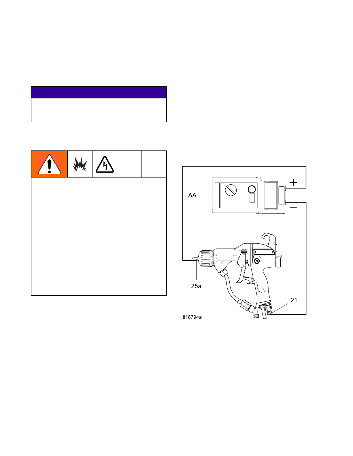
Use megohmmeter Part No. 241079 (AA) with an
applied voltage of 500 V. Connect the leads as
shown.
Megohmmeter Part No. 241079 (AA-see Fig.
17) is not approved for use in a hazardous area.
To reduce the risk of sparking, do not use the
megohmmeter to check electrical grounding
unless:
• The gun has been removed from the hazardous
area;
Test Gun Resis
1. Flush and dry the fluid passage.
2. Measure resistance between the electrode
needle tip (25a) and the air swivel (21). The
resistance should be:
• 106–150 meg
• 150–195 meg
If outside t
Test Power
range, see
other poss
Electrical Troubleshooting, page 37 for
ible causes of poor performance.
tance
ohms for 60 kV guns
ohms for 85 kV guns
his range, go to
Supply Resistance, page 33.Ifin
• Or all spraying devices in the hazardous area
are turned off, ventilation fans in the hazardous
area are operating, and there are no flammable
vapors in the area (such as open solvent
containers or fumes from spraying).
Failure to follow this warning could cause fire,
explosion, and electric shock and result in serious
injury and property damage.
Figure 17 Test Gun Resistance
32 3A2495C
Page 33
Electrical Test
s
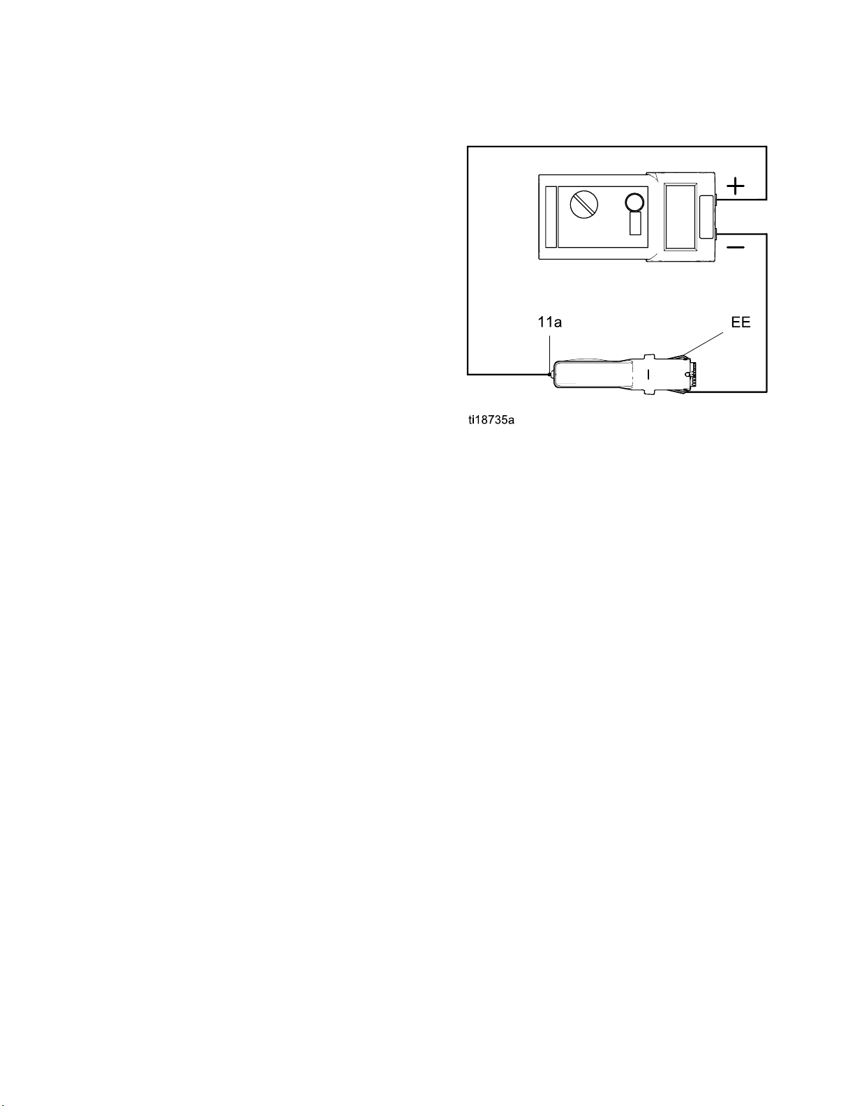
Test Power Sup
1. Remove the power supply (11). See Power
Supply Removal and Replacement, page 45.
2. Remove the alternator (15)
from the power supply. See
Alternator Removal and Replacement, page 46.
3. Measure resistance from the power supply's
ground strips (EE) to the spring (11a). The
resistance should be:
• 86–110 mego
• 130–160 me
4. If outside
power supp
Test Gun Ba
5. If you sti
Electric
other pos
contact y
this range, replace the
ll have problems, refer to
al Troubleshooting on page 23 for
sible causes of poor performance, or
our Graco distributor.
ply Resistance
hms for 60kV guns
gohms for 85kV guns
ly. If in range, go to
rrel Resistance, page 34.
6. Be sure the spring (11a) is in place before
reinstalling the power supply.
Figure 18 Test Power Supply Resistance
3A2495C 33
Page 34
Electrical Test
s
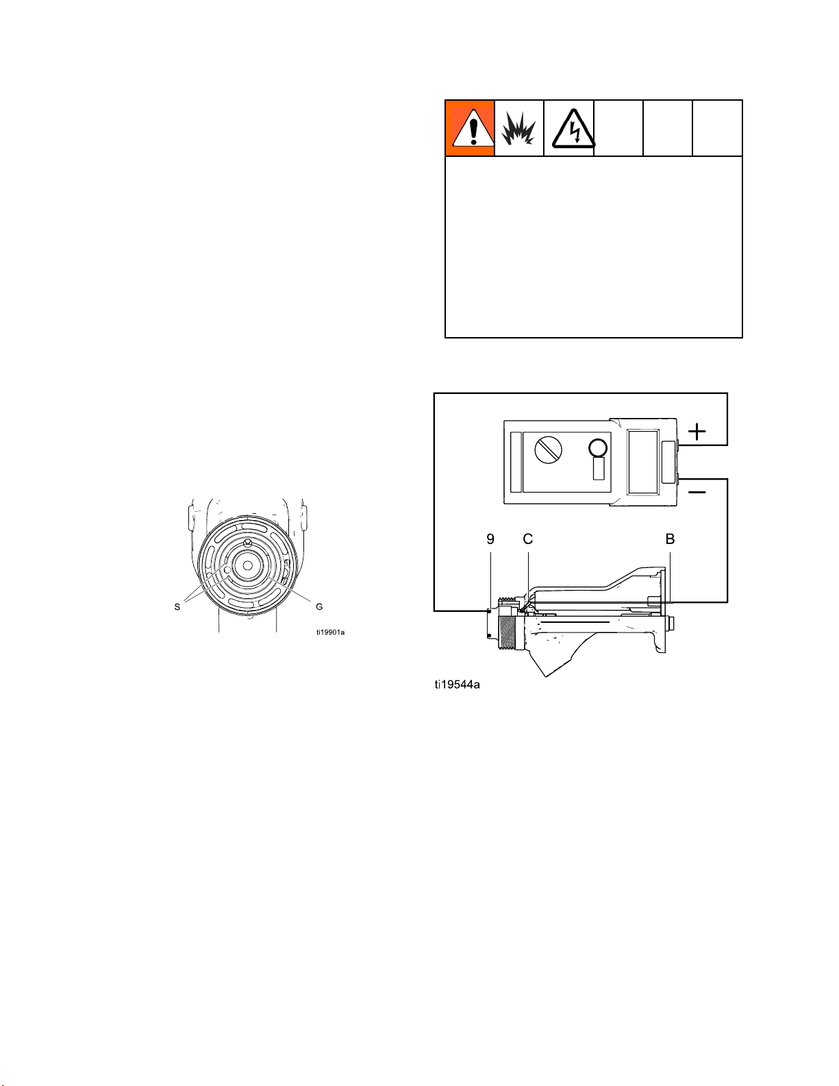
Test Gun Barre
1. Insert a conductive rod (B) into the gun barrel
(which was removed for the power supply test)
and against the metal contact (C) in the front of
the barrel.
2. Measure the resistance between the conductive
rod (B) and the conductive ring (9). The
resistance should be 10–30 megohms. If the
resistance is incorrect, make sure the metal
contact (C) in the barrel and the conductive ring
(9) are clean and undamaged.
3. If the resistance is still outside the range,
remove the conductive ring (9) and measure the
resistance between the conductive rod (B) and
the wire lead at the bottom of the conductive ring
groove.
4. If the resistance is in range, replace the
conductive ring (9) with a new one. Insert the
ends of the conductive ring into the slots (S) at
the front of the barrel, then press the ring firmly
intothegroove(G).
l Resistance
The conductive ring (9) is a conductive (metal)
contact ring, not a sealing o-ring. To reduce
the risk of fire, explosion, or electric shock:
•Donotremove
to replace it
• Never operat
ring in place
• Do not repla
anything bu
5. If the resistance is still outside the range, replace
the gun barrel.
the conductive ring except
.
e the gun without the conductive
.
ce the conductive ring with
t a genuine Graco part.
Figure 19 Test Gun Barrel Resistance
34 3A2495C
Page 35
Troubleshooting
Troubleshootin
g
Installing and servicing this equipment requires
access to parts which may cause an electric shock
or other serious injury if the work is not performed
properly. Do not install or service this equipment
unless you are trained and qualified.
NOTE: Check all possible remedies in the Troubleshooting Chart before disassembling the gun.
To reduce the risk of a skin injection injury, always
follow the Pressure Relief Procedure, page 27,
whenever you are instructed to relieve the
pressure.
Spray Pattern Troubleshooting
NOTE: Some spray pattern problems are caused by the improper balance between air and fluid.
Problem
Fluttering or spitting spray.
Irregular pattern.
Cause Solution
No fluid. Refill supply.
Air in fluid supply. Check fluid source. Refill.
Fluid buildup; partially plugged tip.
Worn/damaged tip or air cap holes.
Clean. See
Clean the Gun Daily, page 29.
Clean or replace.
ern pushed to one side; air
Patt
ets dirty.
cap g
Tails in pattern.
Fluid buildup on air cap/tip guard.
ap holes plugged.
Air c
Air pressure too low.
Fluid pressure too low. Increase.
Air pressure too high. Decrease.
luid pressure too low.
F
Air cap holes plugged.
Clean. See
Clean the Gun Daily, page 29.
n atomizing air adjustment
Ope
ve.
val
ncrease.
I
Clean. See
Clean the Gun Daily, page 29.
3A2495C 35
Page 36

Troubleshootin
g
Gun Operation
Problem
Excessive spray fog.
“Orange Peel” finish.
eaks from the fluid packing
Fluid l
area.
Air leaks from the front of the gun.
Fluid leakage from the front of the
gun.
Troubleshooting
Cause Solution
Atomizing air
Fluid too thin.
Atomizing air pressure too low.
Spray tip is too large. Use smaller tip. See Spray Tip
Poorly m
Fluid too thick. Reduce viscosity.
Worn flu
Air valve is not seating properly.
Worn or damaged fluid needle ball. See Fluid Needle Replacement,
pressure too high.
ixed or filtered fluid.
id needle packings or rod.
Close atomizing air valve part way,
or decrease air pressure as low
as possible; minimum 45 psi (0.32
MPa, 3.2 bar) needed at gun for
full voltage.
Increase vi
flow rate.
Open atomizing air valve more or
increase gun air inlet pressure;
use lowest air pressure necessary.
Selection Chart, page 62.
Remix or
See Flu
page 44.
See Air Valve Repair, page 51.
page 44.
scosity or increase fluid
refilter fluid.
id Needle Replacement,
fluid seat housing.
Worn
Loose spray tip. Tighten retaining ring.
Damaged tip seal.
Gun does not spray.
Dirty air cap. Damaged or plugged air cap.
Excessive paint wrap back to
operator.
Low fluid supply. Add fluid if necessary.
amaged spray tip.
D
Dirty or clogged spray tip.
Damaged fluid needle. See Fluid Needle Replacement,
Poor grounding.
Incorrect distance from gun to part. Should be 8–12 in. (200–300 mm).
ir Cap, Spray Tip, and Fluid
See A
t Housing Replacement, page
Sea
40.
e Air Cap, Spray Tip, and Fluid
Se
at Housing Replacement, page
Se
40.
eplace.
R
Clean. See
Clean the Gun Daily, page 29.
page 44.
Clean air cap. See
Clean the Gun Daily, page 29.
See Grounding, page 21.
36 3A2495C
Page 37

Electrical Troubleshooting
Troubleshootin
g
Problem
Poor wrap.
Cause Solution
ES On/Off switch is OFF (O). Turn ON (I).
Gun air pressure too low (ES
indicator is amber).
Atomizing air pressure too high. Decrease.
Fluid press
Incorrect distance from gun to part. Should be 8-12 in. (200-300 mm).
Poorly gro
Faulty gun resistance.
Low fluid resistivity. See
Fluid l
packin
Faulty alternator.
ES On/Off switch is OFF (O). Turn ON (I).ES or Hz indicator is not lit.
ure too high.
unded parts.
eaks from the fluid needle
gs and causes a short.
Check air pressure to gun;
minimum45psi(0.32MPa,3.2
bar) needed at gun for full voltage.
Decrease, o
Resistanc
less. Cle
See
Test Gun Resistance, page 32.
Check Fluid Resistivity, page 26.
See Flu
page 44.
See Alternator Removal and
Replacement, page 46.
r replace worn tip.
e must be 1 megohm or
an workpiece hangers.
id Needle Replacement,
perator gets shock from
O
workpiece.
No power.
Operator not grounded or is near
ungrounded object.
Gun not grounded. See Check Gun Electrical
Workpiece not grounded. Resistance must be 1 megohm or
k power supply, alternator,
Chec
lternator ribbon cable. See
and a
er Supply Removal and
Pow
lacement, page 45 and
Rep
ernator Removal and
Alt
lacement, page 46.
Rep
See Grounding, page 21.Operator gets mild shock.
Grounding, page 25,and
Test Gun Resistance, page 32.
less. Clean workpiece hangers.
3A2495C 37
Page 38

Troubleshootin
g
Problem
Voltage/current display stays red
(smart guns only).
ES or Hz indi
ES or Hz indicator is red.
Error display appears and Hz
indicator is red (Smart guns only).
cator is amber.
Cause Solution
Gun is too clos
sprayed.
Check fluid resistivity. See
Dirty gun.
Alternator speed is too low. Increase air pressure until
Alternat
Smart module has lost
communication with the power
supply.
or speed is too high.
e to the part being
Gun should be 8
mm) from the pa
Check Fluid Resistivity, page 26.
See Clean the Gun Daily, page 29.
indicator is green. To avoid
over-atomization, use the
atomizing air restrictor valve to
reduce the atomizing air to the air
cap.
Decrease
indicato
Check for good connections
between Smart Module and
power supply. See Smart Module
Replacement, page 52 and
Power Supply Removal and
Replacement, page 45.
r is green.
–12 in. (200–300
rt.
air pressure until
38 3A2495C
Page 39
Repair
Prepare the Gun for Service
Installing and repairing this equipment requires
access to parts that may cause electric shock or
other serious injury if the work is not performed
properly. Do not install or service this equipment
unless you are trained and qualified.
To reduce the risk of injury, follow the
Pressure Relief Procedure, page 27, before
checking or servicing any part of the system
and whenever you are instructed to relieve the
pressure.
• Check all
Trouble
the gun.
possible remedies in
shooting, page 35, before disassembling
Repair
• Use a vise with padded jaws to prevent damage
to plastic parts.
• Lubricate the some needle assembly parts (20)
and certain fluid fittings with dielectric grease (57),
as specified in the text.
• Lightly lubricate o-rings and seals with non-silicone
grease. Order Part No. 111265 Lubricant. Do not
over-lubricate.
• Only use genuine Graco parts. Do not mix or use
parts from other Pro Gun models.
• Air Seal Repair Kit 24N789 is available. The
kit must be purchased separately. Kit parts are
marked with an asterisk, for example (3*).
1. Flush the gun. See Flushing, page 28.
2. Relieve the pressure. See
Pressure Relief Procedure, page 27.
3. Disconnect the gun air and fluid lines.
4. Remove t
must be c
he gun from the worksite. Repair area
lean.
3A2495C 39
Page 40
Repair
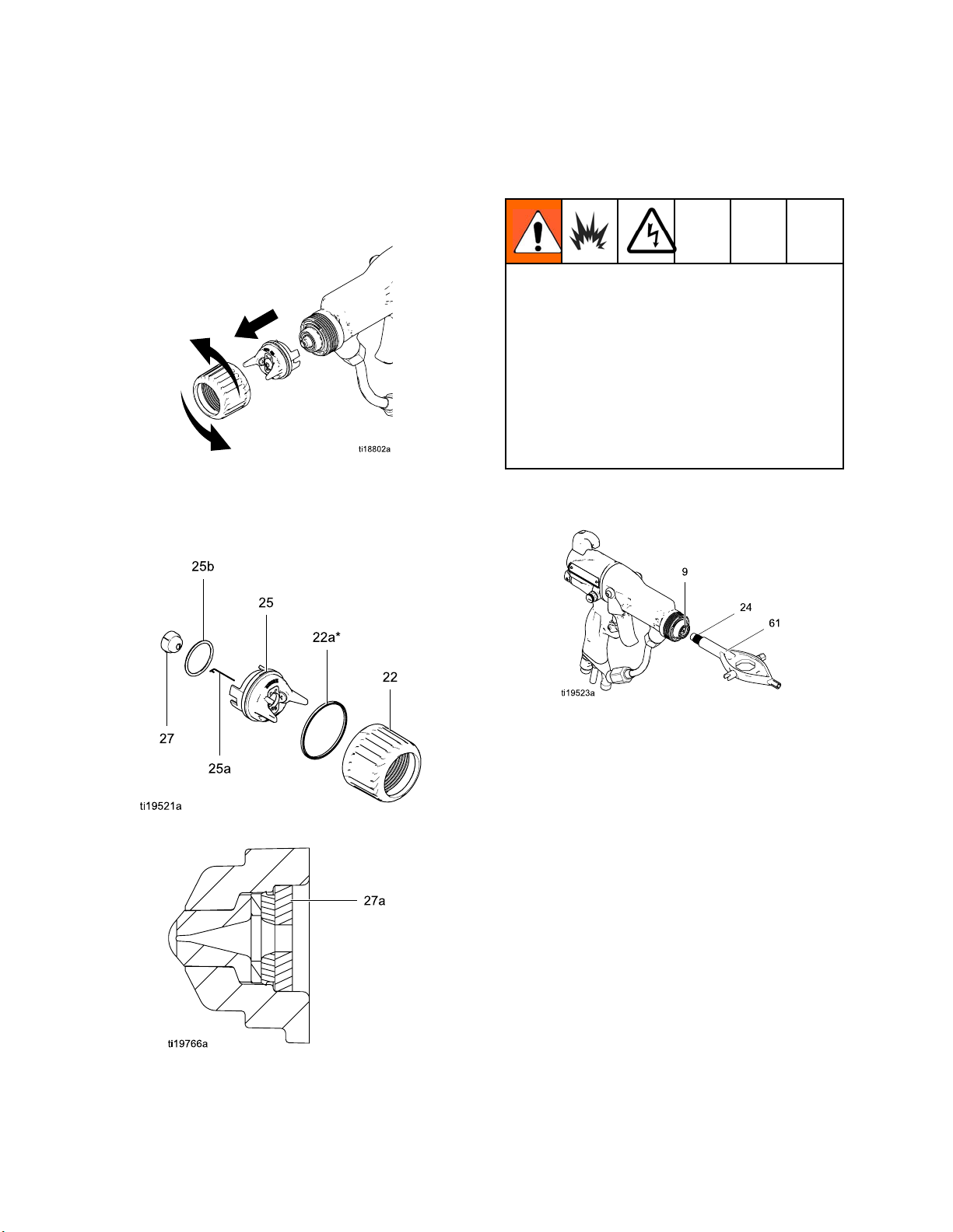
Air Cap, Spray
1. See Prepare the Gun for Service, page 39.
2. Remove the retainer ring (22) and air cap/tip
guard assembly (25).
Figure 20 Remove Air Cap
3. Disassemble the air cap assembly. Check the
condition of the u-cup (22a), o-ring (25b), and tip
gasket (27a). Replace any damaged parts.
Tip, and Fluid Seat Housing Replacement
4. To replace the electrode (25a), see
Electrode Replacement, page 41.
The conductive ring (9) is a conductive metal
contact ring, not a sealing o-ring. To reduce
the risk of fire, explosion, or electric shock:
• Do not remove the conductive ring except
to replace it.
• Never operate the gun without the conductive
ring in place.
• Do not replace the conductive ring with
anything but a genuine Graco part.
5. Trigger the gun and remove the fluid seat housing
(24), using the multi-tool (61).
Figure 21 Disassemble Air Cap Assembly
gure 22 Tip Gasket
Fi
Figure 23 Replace Fluid Seat Housing
40 3A2495C
Page 41
Repair
NOTICE
Do not overtighten the fluid seat housing (24).
Overtightening may damage the housing and
the gun barrel, resulting in improper fluid
shutoff.
6. Trigger the g
(24). Tighte
7. Check that t
Align the sp
cap (25). In
8. Make sure t
correctly
9. Check that
10. Check that
retainin
face forw
un and install the fluid seat housing
n until snug, then 1/4 turn more.
he spray tip gasket (27a) is in place.
ray tip tab with the groove in the air
stall the spray tip (27) in the air cap.
hat the electrode (25a) is installed
in the air cap.
the air cap o-ring (25b) is in place.
the u-cup (22a) is in place on the
gring(22). Thelipsoftheu-cupmust
ard.
NOTICE
To avoid
air cap a
retaini
when the
damaging the tip guard, orient the
ssembly (25) before tightening the
ng ring (22). Do not turn the air cap
retaining ring is tight.
Electrode Replacement
To reduce the risk of fire, explosion, or electric
shock, do not operate the spray gun without the
electrode installed in the air cap.
1. See Prepare the Gun for Service, page 39.
2. Remove the air cap assembly (25). See
Air Cap, Spray Tip, and Fluid Seat Housing
Replacement, page 40.
3. Pull the electrode (25a) out of the back of the air
cap, using a needle-nose pliers.
4. Push the new electrode through the air cap hole.
Make sure the short end (BB) of the electrode
engages the hole (CC) in the back of the air
cap. Press the electrode in place firmly with your
fingers.
5. Install the air cap assembly.
6. See Test Gun Resistance, page 32.
11. Orientate the air cap and tighten the retaining
ring securely.
12. See Test Gun Resistance, page 32.
Figure 24 Replace Electrode
3A2495C
41
Page 42
Repair
Fluid Tube Removal and Replacement
1. See Prepare th
2. Disconnect th
3. Carefully uns
e Gun for Service, page 39.
e bottom fluid tube nut (C).
crew the top fluid tube nut (D).
NOTICE
Be careful not to damage the fluid tube
assembly (19) when cleaning or installing
it, especially the sealing surface (E). If the
sealing surface is damaged, the entire fluid
tube assembly must be replaced.
4. Apply diel
the plasti
5. Apply low s
threads.
6. Install t
tighten t
tighter.
barrel.
7. Make sur
fluid fitt
onto the
tight.
ectric grease (57) to the entire length of
c extension on the fluid tube.
trength sealant to the fluid tube nut
he fluid tube into the gun barrel and
he top nut (D) until snug, then 1/2 turn
There will be a gap between the nut and
Do not over-tighten the nut.
e the fluid filter (10) is in place in the
ing. Tighten the bottom nut (C) securely
fitting. Make sure the top nut remains
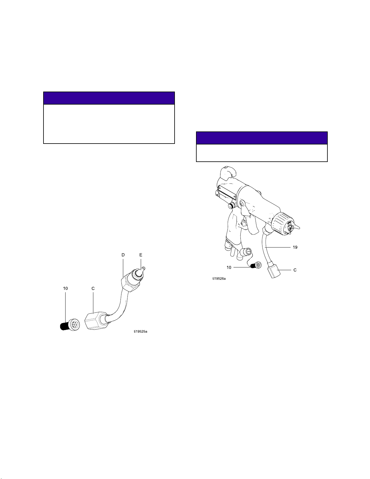
Fluid Filter Replacement
1. See Prepare th
2. Disconnect th
3. Remove the flui
Clean or repl
4. Install the fl
the bottom nu
140–150 in-l
top nut rema
e Gun for Service, page 39.
e bottom fluid tube nut (C).
d filter (10) from the fluid fitting.
ace the filter, as needed.
uid filter (10) in the fluid fitting. Tighten
t (C) onto the fitting and torque to
b (15.8–16.9 N•m). Make sure the
ins tight at 20–30 in-lb (2.3–3.4 N•m).
NOTICE
Be sure the fluid tube (19) is not twisted after
tightening the bottom nut (C).
Figure 25 Fluid Tube
2
4
Figure 26 Replace Fluid Filter
3A2495C
Page 43
Repair
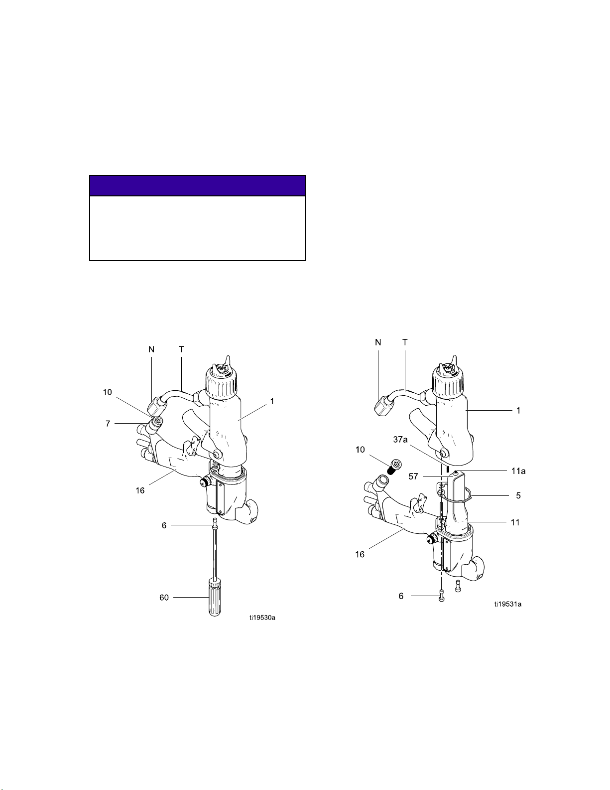
Gun Barrel Rem
1. See Prepare the Gun for Service, page 39.
2. Disconnect the bottom fluid tube nut (N).
Carefully separate the tube assembly (T) from
the bracket (7).
3. Loosen the two screws (6).
oval
NOTICE
To avoid dam
pull the gun
handle. If
barrel fro
handle.
4. Hold the gun handle (16) with one hand and pull
the barrel (1) straight off the handle.
NOTE: If t
remove th
the barr
he power supply remains in the barrel,
e alternator/power supply assembly from
el.
aging the power supply (11),
barrel straight away from the gun
necessary, gently move the gun
msidetosidetofreeitfromthegun
Gun Barrel Ins
1. Be sure the gasket (5*) and grounding spring
(37a) are in place. Make sure the gasket air
holes are aligned properly. Replace the gasket if
damaged.
2. Make sure the spring (11a) is in place on the
tip of the power supply (11). Liberally apply
dielectric grease (57) to the tip of the power
supply. Place the gun barrel (1) over the power
supply and onto the gun handle (16).
3. Tighten the two screws (6) oppositely and evenly
(about a half turn past snug). Do not over-tighten
the screws (6).
4. Make sure the fluid filter (10) is in place in the
fluid fitting. Tighten the bottom nut (N) onto the
fitting and torque to 140–150 in-lb (15.8–16.9
N•m). Make sure the top nut remains tight.
5. See Test Gun Resistance, page 32.
tallation
Figure 28 Gun Barrel Installation
Figure 27 Gun Barrel Removal
3A2495C 43
Page 44
Repair
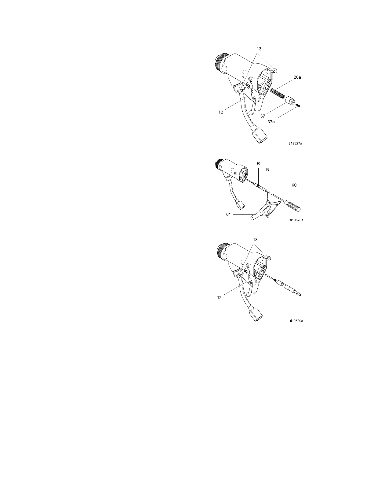
Fluid Needle Replacement
1. See Prepare th
2. Remove the air
housing. See A
Housing Repla
3. Remove the gu
Gun Barrel Re
4. Remove the tr
5. Unscrew the
(20a).
6. Insert the s
back of the
segments o
the needle
7. Using the m
nut (N) to
8. Install t
Push in on
tighten.
9. Install
10. Install
groundi
he fluid needle assembly in the gun barrel.
thespring(20a).
the spring cap (37). Make sure the
igger screws (13) and trigger (12).
spring cap (37). Remove the spring
upplied driver (60) in the socket at the
fluid needle. Press forward so the two
f the needle engage (R). This allows
to be unscrewed from the gun body.
ulti-tool (61), pull back on the packing
remove the fluid needle assembly.
the needle with the driver (60) and
ng spring (37a) is in place.
e Gun for Service, page 39.
cap assembly and fluid seat
ir Cap, Spray Tip, and Fluid Seat
cement, page 40.
nbarrel. See
moval, page 43.
Figure 29 Remove Cap and Springs
Figure 30 Remove Fluid Needle
11. Install
12. Instal
13. Instal
14. See Te
l the gun barrel. See
Gun Bar
l the seat housing and air cap assembly.
See Air
Repla
the trigger (12) and screws (13).
rel Installation, page 43.
Cap, Spray Tip, and Fluid Seat Housing
cement, page 40.
st Gun Resistance, page 32.
Figure 31 Replace Fluid Needle
4
4
3A2495C
Page 45
Repair
Power Supply R
• Inspect the gun handle power supply cavity for dirt
or moisture. Clean with a clean, dry rag.
• Do not expose gasket (5) to solvents.
1. See Prepare the Gun for Service, page 39.
2. See Gun Barrel Removal, page 43.
emoval and Replacement
NOTICE
Be careful when handling the power supply
(11) to avoid damaging it.
3. Grasp the power supply (11) with your hand.
With a gentle side to side motion, free the power
supply/alternator assembly from the gun handle
(16), then carefully pull it straight out.
Models only,
from the socket at the top of the handle.
4. Inspect the power supply and alternator for
damage.
5. To separate the power supply (11) from the
alternator (15), disconnect the 3-wire ribbon
connector (PC) from the power supply.
Models only,
(40) from the power supply. Slide the alternator
up and off the power supply.
6. See Test Power Supply Resistance, page 33.
Replace the power supply if necessary.
To repair the alternator, see
Alternator Removal and Replacement, page 46.
7.
Smart models only:
circuit (40) to the power supply.
disconnect the flexible circuit (40)
disconnect the 6–pin flexible circuit
connect the 6–pin flexible
On Smart
On Smart
(EE) make contact with the handle. On Smart
models, align the connector of the 6–pin flexible
circuit (40) with the socket (CS) at the top of the
handle. Push the connector securely into the
socket as you slide the power supply/alternator
assembly into the handle.
Figure 32 Connect Flexible Circuit
10. Make sure the gasket (5*), ground spring (37a),
and power supply spring (11a) are in place.
Assemble the barrel (1) to the handle (16). See
Gun Barrel Installation, page 43.
11. See Test Gun Resistance, page 32.
To prevent damage to the cable and possible
interruption of the ground continuity, bend the
alternator’s 3–wire ribbon cable (PC) upward
and back, so the bend faces the power supply
and the connector is at the top.
8. Connect the 3-wire ribbon connector (PC) to the
power supply. Tuck the ribbon forward, under
the power supply. Slide the alternator (15) down
onto the power supply (11).
9. Insert the power supply/alternator assembly in
the gun handle (16). Make sure the ground strips
Figure 33 Power Supply
3A2495C 45
Page 46
Repair
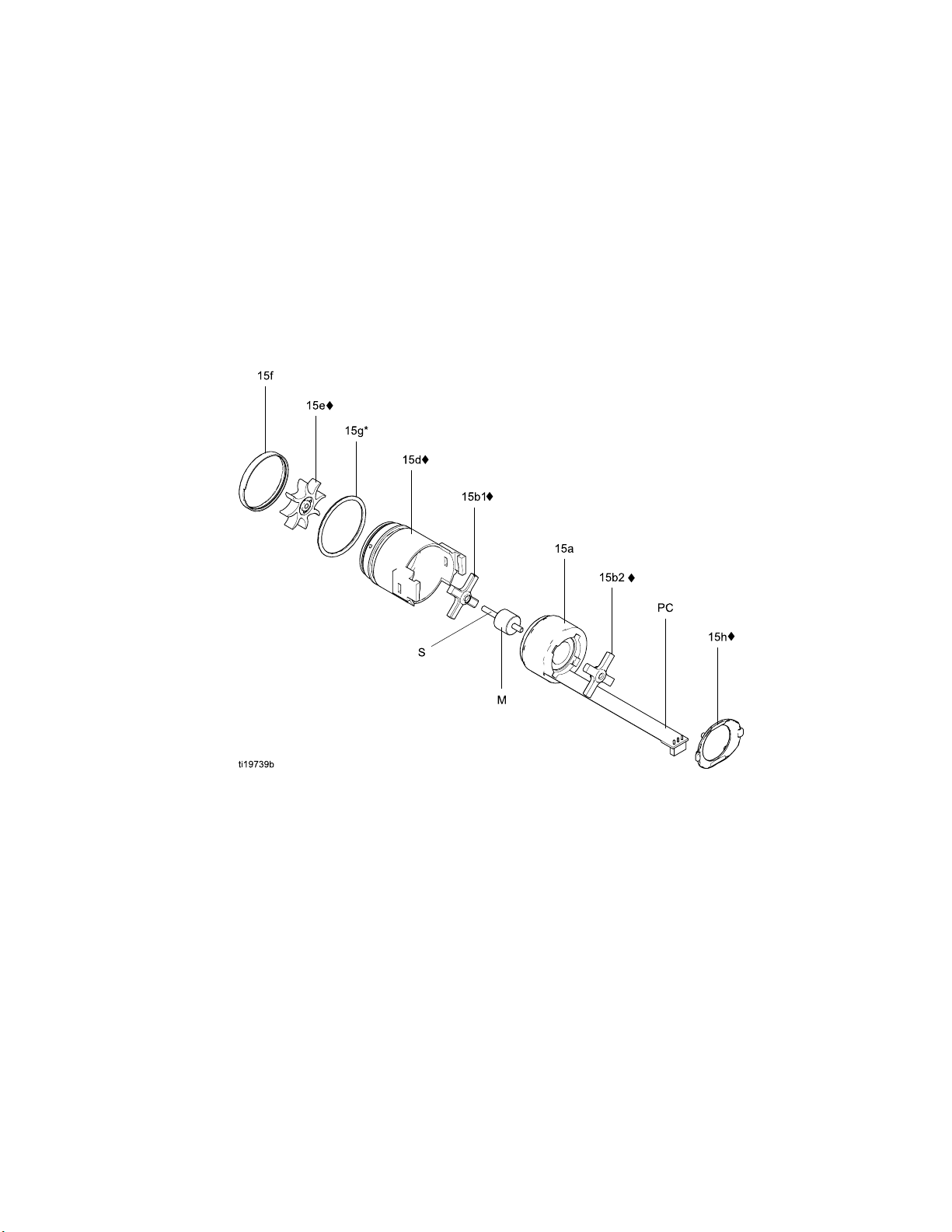
Alternator Removal and Replacement
NOTE: Replace
of operation.
Parts include
1. See Prepare the Gun for Service, page 39.
2. Remove the power supply/alternator assembly
and disconnect the alternator. See Power Supply
Removal and Replacement, page 45.
3. Measure resistance between the two outer
terminals of the 3-wire connector (PC); it should
be 2.0–6.0 ohms. If outside this range, replace
the alternator coil (15a).
4. Using a flat blade screwdriver, pry the clip (15h)
off the housing (15d). Remove the cap (15f),
using a thin blade or screwdriver.
5. If necessary, rotate the fan (15e) so its blades
clear the four bearing tabs (T) of the housing
(15d).
alternator bearings after 2000 hours
Order Part No. 24N706 Bearing Kit.
dinthekitaremarkedwithasymbol(♦).
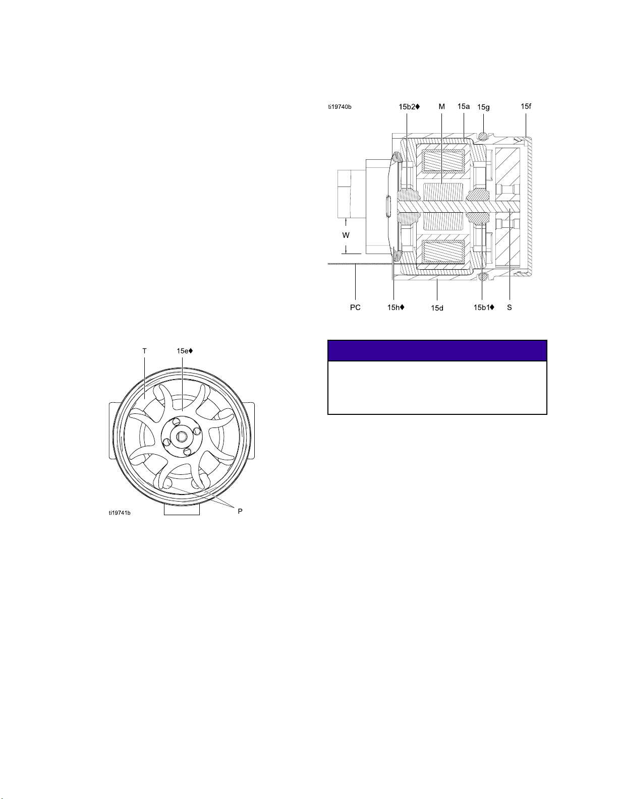
Figure 35
Alternator Cross-Section
NOTICE
Do not scratch or damage the magnet (M) or
shaft (S). Do not pinch or damage the 3–wire
connector (PC) when disassembling and
reassembling the bearings.
Figure 34 Fan Orientation
6. Push the fan and coil assembly (15a) out the
front of the housing (15d).
7. Hold th
with th
screwd
8. Remov
9. Remov
10. Insta
11. Pres
ll the new bottom bearing (15b1♦) on the
long e
ng must face away from the magnet (M).
beari
all in the coil (15a) so the bearing blades are
Inst
flush
s the new top bearing (15b2♦) onto the short
end o
the surface of the coil (15a). The flatter side
with
he bearing must face away from the coil.
of t
e coil assembly (15a) on a workbench
efanendfacingup. Usingawideblade
river, pry the fan (15e) off the shaft (S).
e the top bearing (15b2).
e the bottom bearing (15b1).
nd of the shaft (S). The flatter side of the
with the surface of the coil.
f the shaft so the bearing blades are flush
46 3A2495C
Page 47
Repair
12. Hold the coil assembly (15a) on a workbench
with the fan end facing up. Press the fan (15e♦)
onto the long end of the shaft (S). The fan blades
must be oriented as shown.
13. Carefully press the coil assembly (15a) into
the front of the housing (15d♦). The 3–wire
connector (PC) must be positioned below the
wider notch (W) of the housing tabs, as shown in
Fig. 35. Be sure the coil alignment pins (P) are
positioned as shown in Fig. 34.
14. Rotate the fan (15e) so its blades clear the four
bearing tabs (T) at the back of the housing.
Ensure that the blades of the bottom bearing
(15b1♦) align with the tabs.
15. Seat the coil fully into the housing (15d♦). Secure
with the clip (15h♦), ensuring that its tabs engage
the slots in the housing.
16. Ensure that the o-ring (15g) is in place. Install
the cap (15f).
17. Install the alternator on the power supply, and
install both parts in the handle. See Power
Supply Removal and Replacement, page 45.
Figure 36 Alternator
3A2495C
47
Page 48
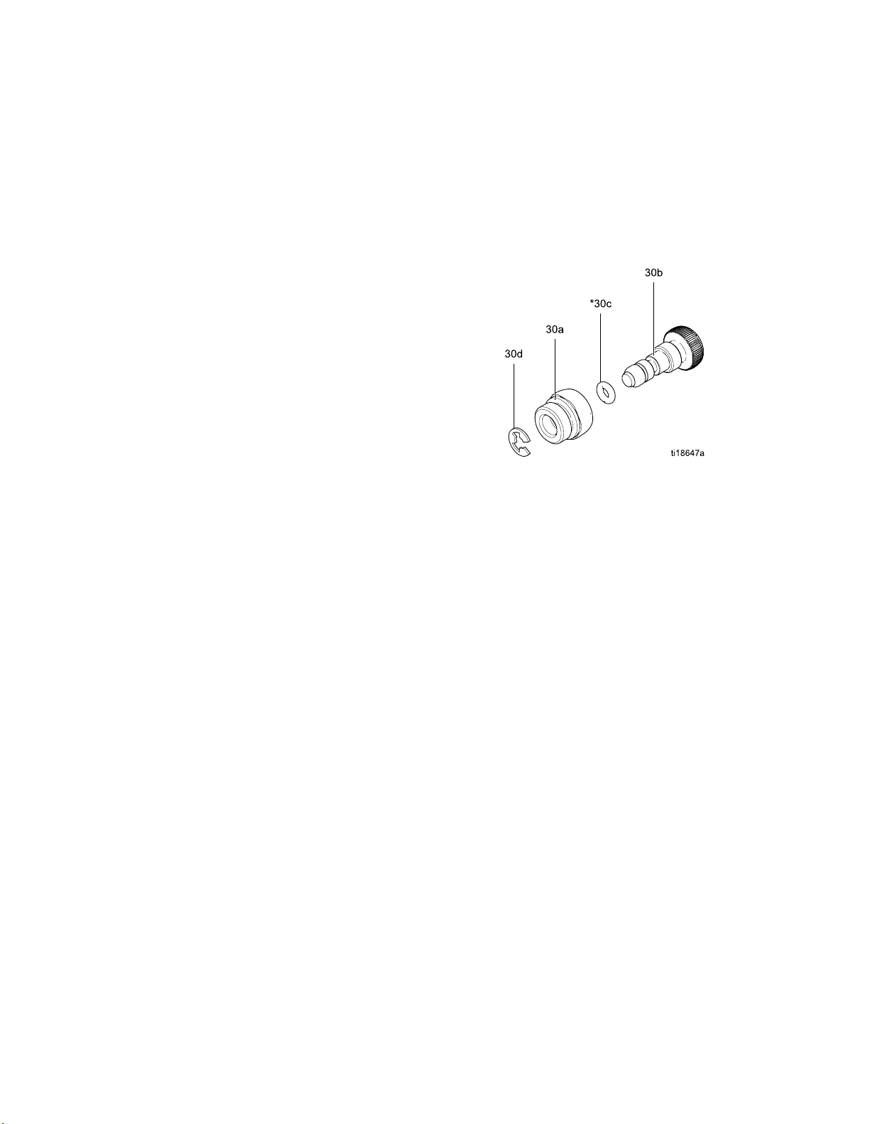
Repair
Fan Air Adjustment Valve Repair
1. See Prepare th
2. Place a wrench
(30) and unscr
NOTE: You may
assembly (go
(steps 3-9).
3. Remove the re
4. Turn the val
it comes fre
5. Remove the o
6. Clean all p
NOTE: Use n
111265. Do
7. When reas
lubricat
(30b) ful
Install t
the valve
ve shaft (30b) counterclockwise until
e from the valve housing (30a).
arts and inspect for wear or damage.
not over-lubricate.
sembling the fan air valve (30), lightly
e the valve threads and screw the shaft
ly into the housing (30a) until bottomed.
he o-ring (30c*), lubricate, and unscrew
stem until the o-ring enters the housing.
e Gun for Service, page 39.
on the flats of the valve assembly
ew it from the handle (16).
replace the valve as an
to step 9) or as individual parts
taining ring (30d).
-ring (30c).
on-silicone grease, Part No.
8. Reassemble th
the valve stem
by the retaini
9. Screw the valv
handle (16),
housing. Tor
Figure 37 Fan Air Adjustment Valve
e retaining ring (30d). Unscrew
from the housing until it is stopped
ng ring.
e assembly (30) into the gun
using a wrench on the flats of the
que to 15 in-lb (1.7 N•m).
48 3A2495C
Page 49

Atomizing Air Adjustment Valve Repair
Repair
1. See Prepare th
2. Place a wrench
(29) and unscr
3. Inspect the v
anewvalve(2
4. Before insta
handle, unsc
housing (29
5. Install the
Torque the v
N•m).
alve assembly. If damaged, install
lling the valve assembly in the
rew the valve stem (29b) from the
a) until it stops.
valve assembly into the gun handle.
alve housing (29a) to 15 in-lb (1.7
e Gun for Service, page 39.
on the flats of the valve assembly
ew it from the handle (16).
9).
Figure 38 Ato
mizing Air Adjustment Valve
3A2495C 49
Page 50
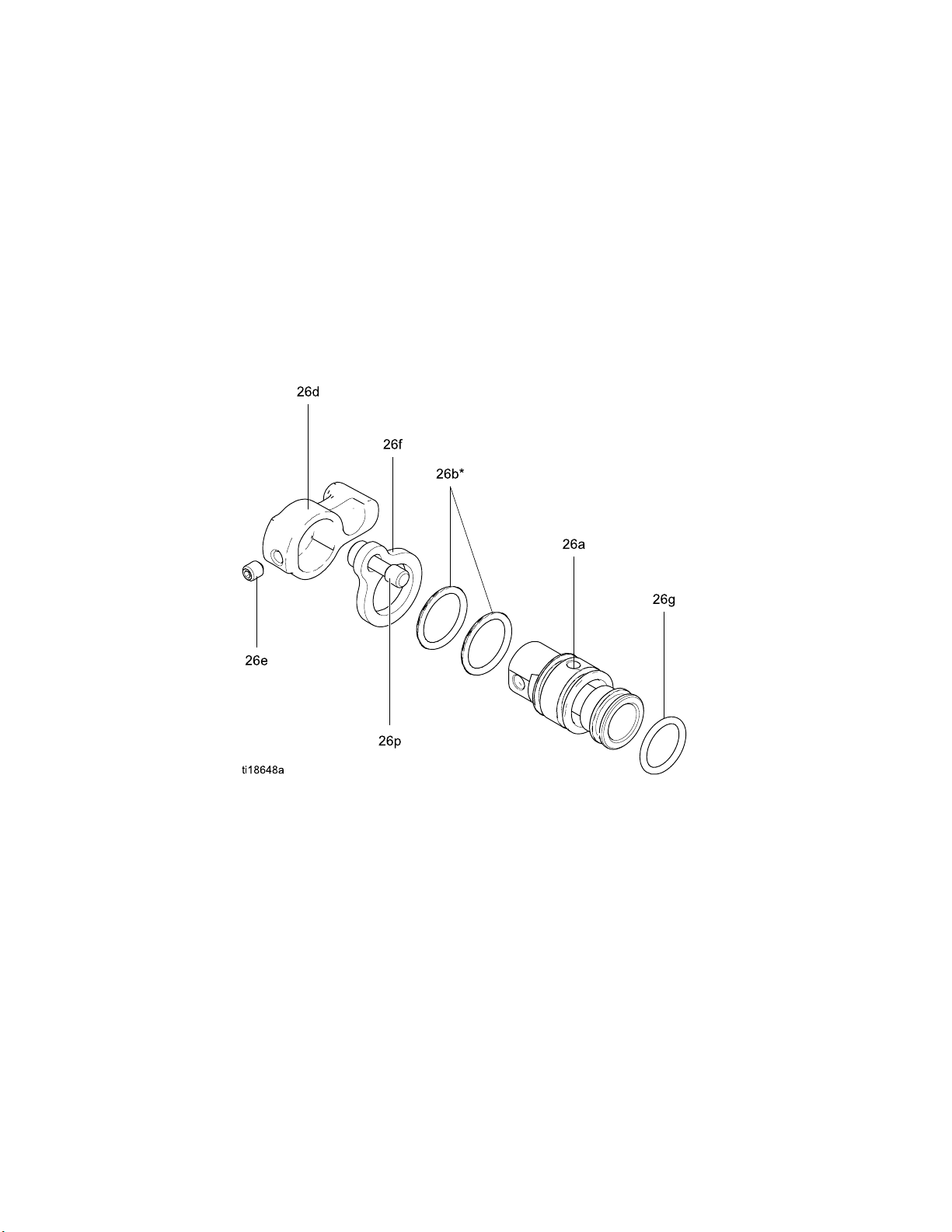
Repair
ES On-Off Valv
1. See Prepare the Gun for Service, page 39.
2. Loosen the captive screw (26p). Remove the
valve (26) from the handle.
3. Lubricate the o-rings (26b* and 26g*) with
non-silicone grease, Part No. 111265. Do not
over-lubricate.
NOTE: Do not
lubricant o
gun air pass
workpiece
ntheo-ringscanbepushedintothe
.
e Repair
over-lubricate parts. Excessive
age and blemish the finish on the
4. Clean and inspect parts for damage. Replace
if necessary.
NOTE: The pro
must point up
5. Reinstall th
15-25 in-lb (
trusion on the retainer plate (26f)
ward.
e valve. Torque the screw (26p) to
1.7-2.8 N•m).
Figure 39 ES On-Off Valve
50 3A2495C
Page 51
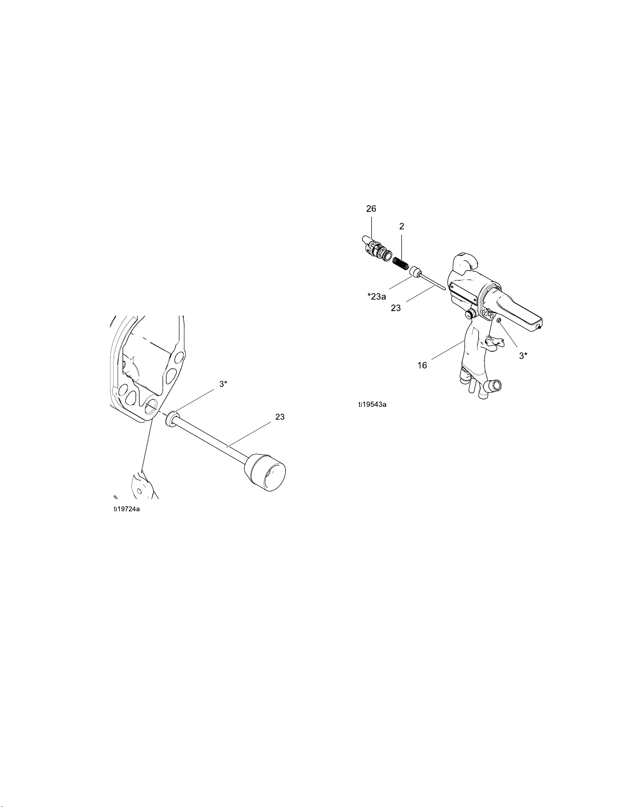
Air Valve Repair
Repair
1. See Prepare th
2. See Gun Barrel
3. Remove the scr
4. Remove the ES
ES On-Off Val
5. Remove the sp
6. Push on the f
out the back
seal (23a*)
7. Inspect the
unless dam
with its li
the u-cup o
it in the gu
ve Repair, page 50.
ront of the air valve shaft to force it
of the handle. Inspect the rubber
and replace if damaged.
u-cup (3). Do not remove the u-cup
aged. If removed, install the new one
ps facing into the gun handle (16). Place
n the shaft of the air valve to help seat
n handle.
e Gun for Service, page 39.
Removal, page 43.
ews (13) and trigger (12).
On-Off Valve. See
ring (2).
8. Install the ai
gun handle (16
9. Install the ES
ES On-Off Valv
10. Install the t
11. See Gun Barre
r valve (23) and spring (2) into the
rigger (12) and screws (13).
).
On-Off Valve. See
e Repair, page 50.
l Installation, page 43.
Figure 40 Install U-Cup
Figure 41 Air Valve
3A2495C 51
Page 52
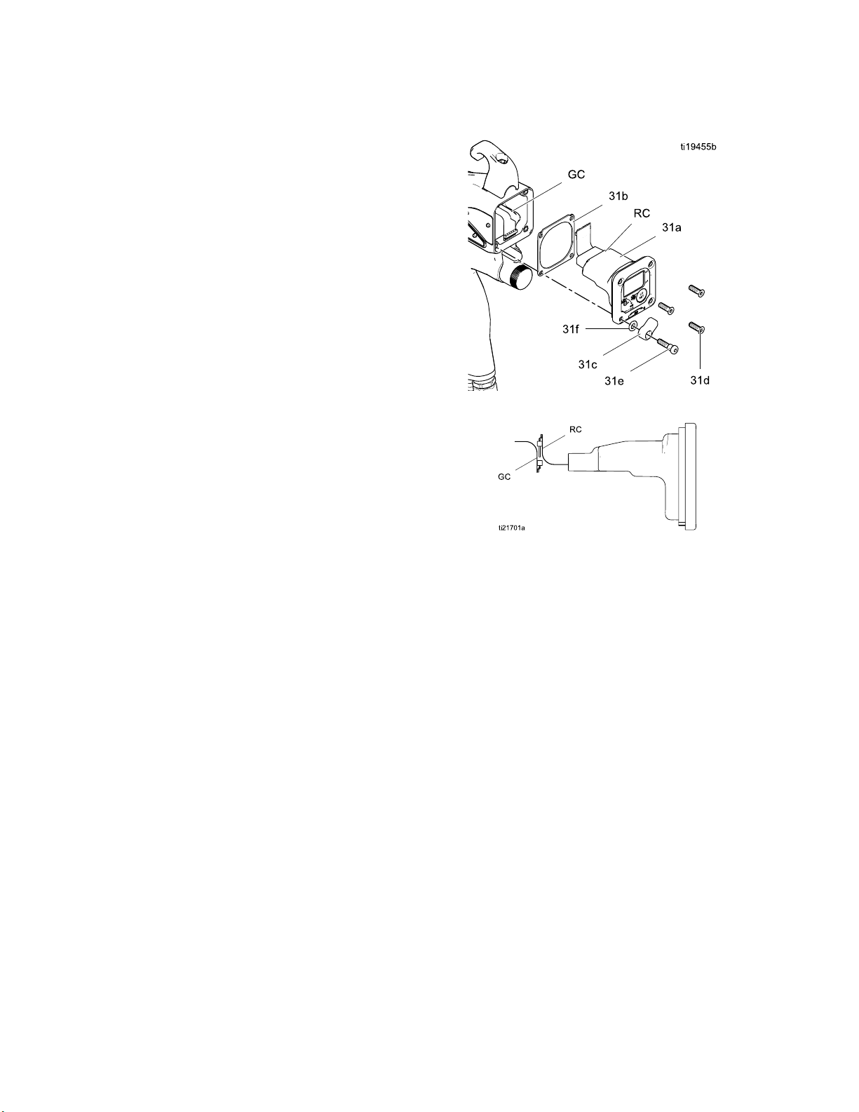
Repair
Smart Module R
If the Error display appears, the Smart Module has
lost communication with the power supply. Check for
good connections between the Smart Module and
the power supply.
If the module
module.
1. See Prepare the Gun for Service, page 39.
2. Remove the pivot screw (31e), o-ring (31f), and
ES HI/LO switch (31c) at the bottom left corner of
the Smart Module cartridge (31a).
3. Remove the remaining three screws (31d) from
the cartridge.
4. Pull the Smart Module out the back of the gun.
Disconnect the ribbon cable (RC) from the
connector (GC) in the gun handle.
5. Remove the gasket (31b).
6. Install a new gasket (31b) on the new cartridge
(31a). Make sure the notched corners of the
gasket are at the top.
’s LEDs are not lighting, replace the
eplacement
Figure 42 Smart Module
7. Align the module’s ribbon cable (RC) with
the gun’s cable (GC) and slide them securely
together, as shown. Tuck the connected cables
into the recess of the gun handle. Install the
module flush to the back of the gun handle.
8. Install the pivot screw (31e), o-ring (31f), and
ES HI/LO switch in the bottom left corner of the
cartridge (31a).
9. Install the three remaining screws (31d). Torque
to 7–9 in-lb (0.8–1.0 N•m).
Figure 43 Align Ribbon Cables
52 3A2495C
Page 53
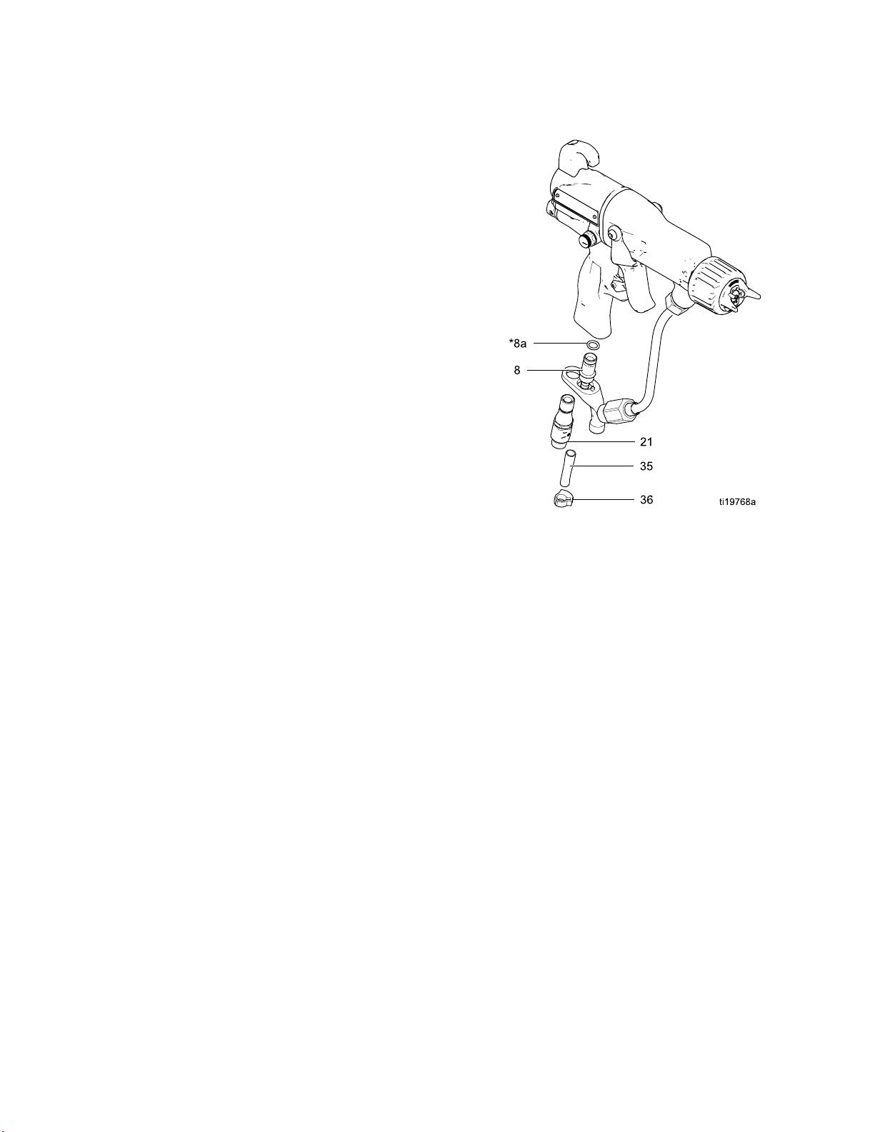
Repair
Air Swivel and
1. See Prepare the Gun for Service, page 39.
2. To replace the air exhaust valve:
a. Remove the cl
(35).
b. Unscrew the s
(16). The sw
Remove the b
c. Pull the exh
(16). Inspe
necessary
d. Install th
(8). Lubri
of non-sil
e. Install t
(16).
f. Apply thr
the swive
screw th
Torque t
g. Install
Exhaust Valve Replacement
amp (36) and the exhaust tube
wivel (21) from the gun handle
ivel is a left-hand thread.
racket (7).
aust valve (8) from the handle
ct the o-ring (8a) and replace if
.
e o-ring (8a*) on the exhaust valve
cate the o-ring with a light coating
icone grease.
he exhaust valve (8) in the handle
ead sealant to the top threads of
l (21). Position the bracket (7) and
e swivel into the gun handle (16).
o 75–85 in-lb (8.4–9.6 N•m).
the tube (35) and clamp (36).
Figure 44 Air Inlet Fitting and Air Exhaust Valve
3. To repl
a. Unscrew the swivel (21) from the gun handle
b. Apply thread sealant to the top threads of the
ace the air inlet swivel:
(16). The swivel is a left-hand thread.
swivel. Screw the swivel into the gun handle.
Torque to 75–85 in-lb (8.4–9.6 N•m).
3A2495C 53
Page 54
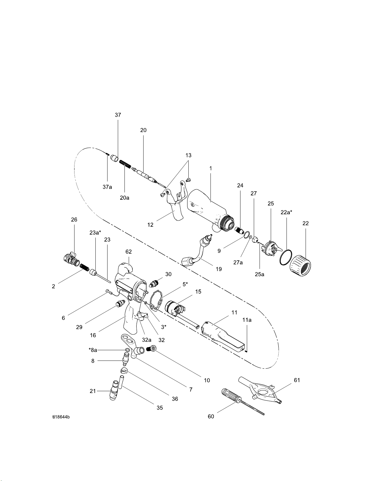
Parts
Parts
Standard Air-Assisted Spray Gun Assembly
Part No. H60T
Part No. H85T
10 60 kV Electrostatic Air-Assisted Spray Gun, Series A
10 85 kV Electrostatic Air-Assisted Spray Gun, Series A
54 3A2495C
Page 55

Part No. H60T10 60 kV Electrostatic Air-Assisted Spray Gun, Series A
Part No. H85T10 85 kV Electrostatic Air-Assisted Spray Gun, Series A
Parts
Ref.
No.
2 185116
3*
5*
624N740
7
8 249323 VALVE, exhaust 1
8a*
924N747
10 238562 FILTER, inline, 100 mesh; see
11
12 24N663
13 24A445
15 24N664
19
20
20a 24N782
21 24N626
22 24N793
22a*
23 24N633 VALVE, air 1
23a*
24 24N725
Part No. Description
24N746
24N745
188749
24N699
24N742
112085
24N660
24N661
24N761 HANDLE; 60 kV AA gun 116
24N762 HANDLE; 85 kV AA gun 1
24N744
24N743
24N780
24N781
198307
276733
BODY, gun; 60 kV gun
BODY, gun; 85 kV gun
SPRING, compression
PACKING, u-cup
GASKET, body
SCREW, hex socket;
package of 2
BRACKET
O-RING
RING, conductive
note below
POWER SUP
POWER SUP
TRIGGER;
SCREW, t
See
Alterna
TUBE, fluid; 60 kV gun
TUBE, fluid; 85 kV gun
NEEDLE ASSEMBLY; 60 kV
gun; includes item 20a
NEEDLE ASSEMBLY; 85 kV
gun; includes item 20a
SPRIN
EL, air inlet; M12 x 1/4
SWIV
(m); left-hand thread
npsm
RING, retainer; includes 22a
PACKING, u-cup; UHMWPE;
part of 22
SEAL
HOUSING, seat
PLY, 60 kV gun
PLY, 85 kV gun
includes item 13
rigger; package of 2
tor Assembly, page 58
G, fluid needle
Qty
11
1
1
1
1
1
1
1
1
1
1
1
1
1
1
1
1
1
1
1
1
1
1
1
1
Ref.
No.
25 24N727
25a 24N643
26 24N632
27 AEMxxx
27a 183459
29 24N792
30 24N634
32 24E404
32a
35 185103
36 110231
37 24N785
37a 197624
38 24N786
51 112080
55▲
56▲ 16P80
57
58 117824
60 107460
61 276
62 24N
Part No. Description
AEFxxx
———
24N603
24N604
17979
53
1165
741
783
See Air Cap Assembly, page 61
ELECTRODE; package of 5
See ES On-Off Valve Assembly,
page 59
TIP ASSEMBLY; customer’s
choice; includes item 27a
GASKET, tip
ATOMIZING AIR
ADJUSTMENT VALVE
See Fan Air Valve Assembly,
page 60
STOP, trigger; includes item 32a
PIN, dowel 1
TUBE, exhaust; 1/4 in. (6 mm)
ID (shipped loose)
CLAMP
CAP, spr
SPRING,
PLUG, fa
shippe
of item
TOOL, needle (shipped loose)
COVER, gun, 60 kV guns;
package of 10
COVER, gun, 85 kV guns;
package of 10
1
TAG, warning (not shown)
2
SIGN, warning (not shown)
GREASE, dielectric; 1 oz (30
ml) tube (not shown)
GLOVE, conductive, medium;
package of 12; also available
in small (117823) and large
(117825)
TOOL, wrench, ball end
(shipped loose)
MULTI-TOOL (shipped loose)
HOOK; includes screw
ing; includes item 37a
compression
n control; option,
d loose for use in place
29
Qty
1
1
1
1
1
1
1
1
1
1
1
1
1
1
154
1
1
1
1
1
1
1
1
▲ Replacement Danger and Warning labels, tags,
and cards are available at no cost.
These parts are included in Air Seal Repair Kit
*
4N789 (purchase separately).
2
NOTE: 100 mesh Filter Kits (10) are available. Order
238561 (qty 3) or 224453 (qty 5).
arts labeled — — — are not available separately.
P
3A2495C 55
Page 56
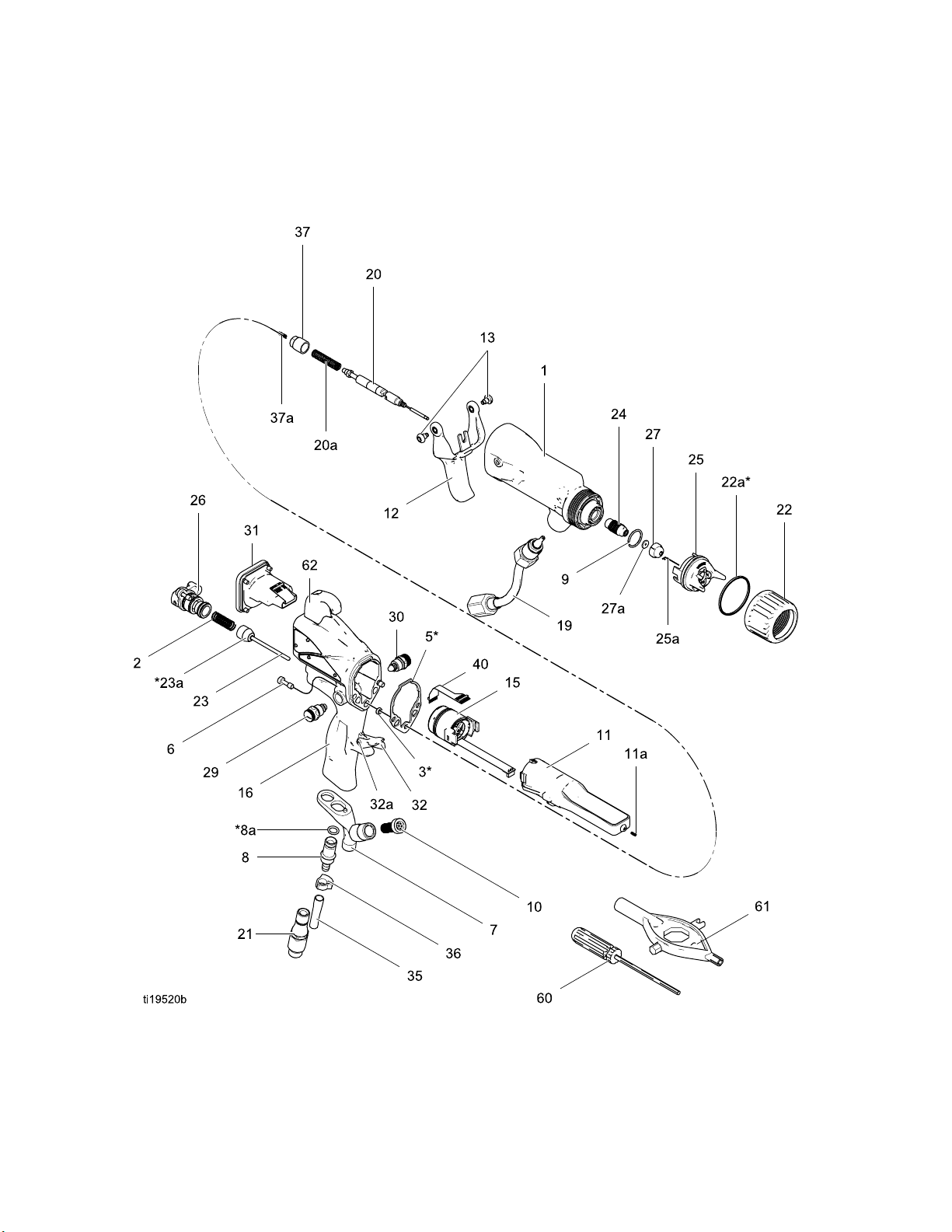
Parts
Smart Air-Ass
Part No. H60M10 60 kV Electrostatic Air-Assisted Spray Gun, Series A
Part No. H85M10 85 kV Electrostatic Air-Assisted Spray Gun, Series A
isted Spray Gun Assembly
56 3A2495C
Page 57

Part No. H60M10 60 kV Electrostatic Air-Assisted Spray Gun, Series A
Part No. H85M10 85 kV Electrostatic Air-Assisted Spray Gun, Series A
Parts
Ref.
No.
2 185116
3*
5*
624N740
7
8 249323 VALVE, exhaust 1
8a*
924N747
10 238562 FILTER, inline, 100 mesh; see
11
12 24N663
13 24A445
15 24N664
19
20
20a 24N782
21 24N626
22 24N793
22a*
23 24N633 VALVE, air 1
23a*
24 24N725
25 24N727
Part No. Description
24N746
24N745
188749
24N699
24N742
112085
24N660
24N661
24N763 HANDLE, smart; 60 kV AA gun 116
24N764 HANDLE, smart; 85 kV AA gun 1
24N744
24N743
24N780
24N781
198307
276733
BODY, gun; 60 kV gun
BODY, gun; 85 kV gun
SPRING, compression
PACKING, u-cup
GASKET, body
SCREW, hex socket; sst;
package of 2
BRACKET
O-RING
RING, conductive
note below
POWER SUP
POWER SUP
TRIGGER;
SCREW, t
See
Alterna
TUBE, fluid; 60 kV gun
TUBE, fluid; 85 kV gun
NEEDLE ASSEMBLY; 60 kV
gun; includes item 20a
NEEDLE ASSEMBLY; 85 kV
gun; includes item 20a
SPRIN
EL, air inlet; M12 x 1/4
SWIV
(m); left-hand thread
npsm
RING, retainer; includes 22a
PACKING, u-cup; UHMWPE;
part of 22
SEAL
HOUSING, seat
See Air Cap Assembly, page 61
PLY, 60 kV gun
PLY, 85 kV gun
includes item 13
rigger; package of 2
tor Assembly, page 58
G, fluid needle
Qty
11
1
1
1
1
1
1
1
1
1
1
1
1
1
1
1
1
1
1
1
1
1
1
1
1
1
Ref.
No.
25a 24N643
26 24N632
27 AEMxxx
27a 183459
29 24N792
30 24N634
31 24N756
32 24E404
32a
35 185103
36 110231
37 24N785
37a 197624
38 24N786
40 245265
51 112080
54
55▲
56▲ 16P802
57
58 117824
60 107
61 276741
62 24N783
Part No. Description
AEFxxx
———
24N603
24N60
179791
116553
460
ELECTRODE; package of 5
See ES On-Off Valve Assembly,
page 59
TIP ASSEMBLY; customer’s
choice; includes item 27a
GASKET, tip
ATOMIZING AIR
ADJUSTMENT VALVE
See Fan Air Valve Assembly,
page 60
See Smart Module Assembly,
page 61
STOP, tri
PIN, dowel 1
TUBE, exh
ID (shipp
CLAMP
CAP, spring; includes item 37a
SPRING, compression
PLUG, fan control; option,
shipped loose for use in place
of item 29
CIRCUIT, flexible
TOOL, needle (shipped loose)
COVER, gun, 60 kV guns;
package of 10
4
COVER, gun, 85 kV guns;
package of 10
TAG, warning (not shown)
SIGN, warning (not shown)
GREASE, dielectric; 1 oz (30
ml) tube (not shown)
GLOVE, conductive, medium;
package of 12; also available
in small (117823) and large
(117825)
TOOL, wrench, ball end
(shipped loose)
MULTI-TOOL (shipped loose)
HOOK; includes screw
gger; includes item 32a
aust; 1/4 in. (6 mm)
ed loose)
Qty
1
1
1
1
1
1
1
1
1
1
1
1
1
1
1
1
1
1
1
1
1
1
1
1
▲ Replacement Danger and Warning labels, tags,
and cards are available at no cost.
These parts are included in Air Seal Repair Kit
*
4N789 (purchase separately).
2
NOTE: 100 mesh Filter Kits (10) are available. Order
238561 (qty 3) or 224453 (qty 5).
arts labeled — — — are not available separately.
P
3A2495C 57
Page 58
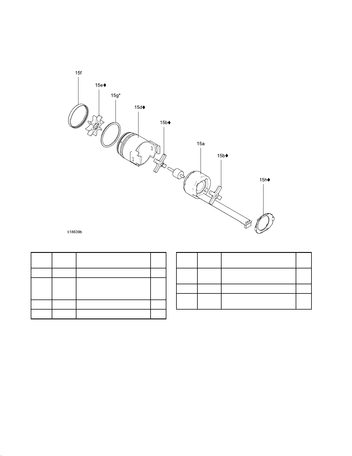
Parts
Alternator Assembly
Part No. 24N66
4 Alternator Assembly
Ref.
No.
15a 24N705
15b♦ 24N706
15d♦ 24N707
15e♦
Part
No.
———
Description
COIL, alternator
BEARING KIT (includes two
bearings, item 15e fan, and
one item 15h clip)
HOUSING; includes item 15f
FAN; part of item 15b
Qty
1
1
1
1
* These parts are included in Air Seal Repair Kit
24N789 (purchase separately).
♦ These parts are included in Bearing Kit 24N706
(purchase separately).
Ref.
No.
15f
15g*
15h♦ 24N709
Part
No.
———
110073
Description
CAP, housing; part of item
15d
O-RING
CLIP; package of 5 (one clip
included with item 15b)
Qty
1
1
1
Parts labeled — — — are not available separately.
58 3A2495C
Page 59
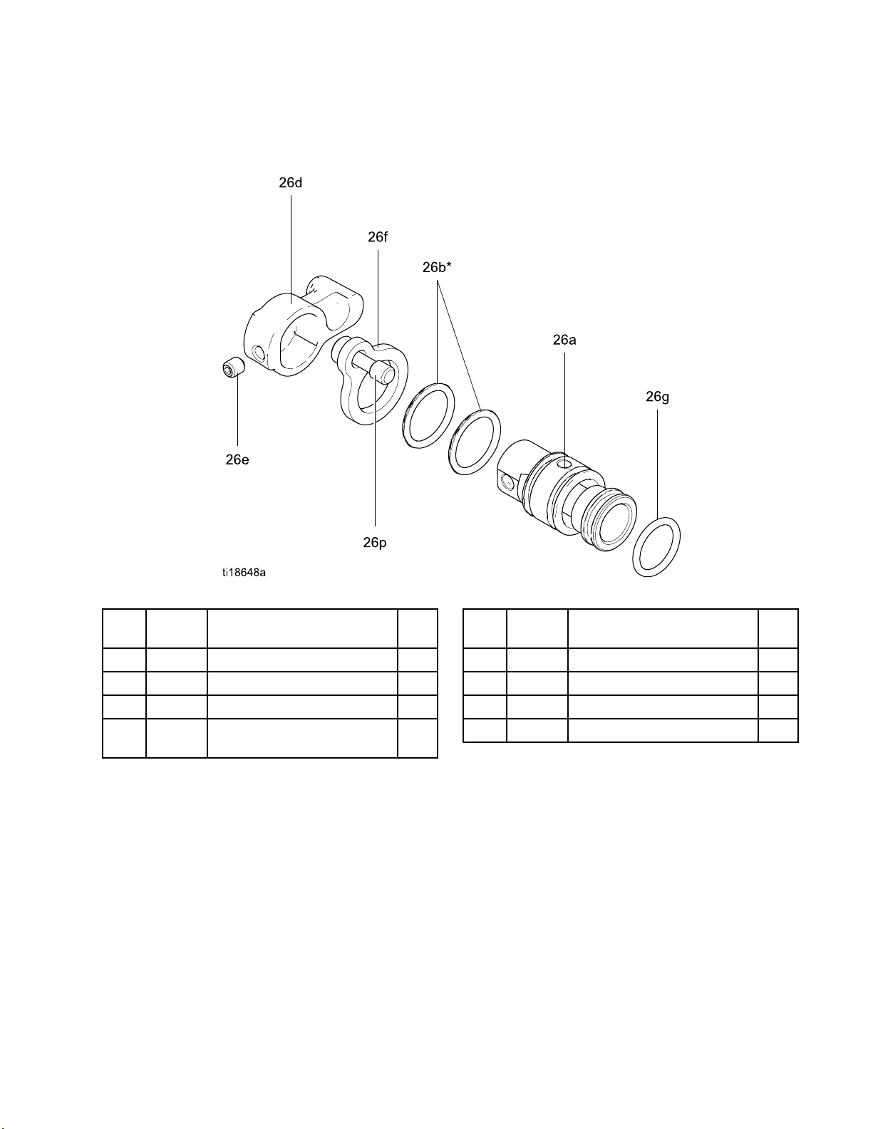
Parts
ES On-Off Valv
e Assembly
Part No. 24N632 ES On-Off Valve Assembly
Ref.
No.
26a
26b*
26c
26d 24N650
Part No. Description
———
15D371
———
HOUSING, valve
G
O-RIN
PISTON, valve
LEVER, ES on-off; includes
item 26e
* These parts are included in Air Seal Repair Kit
24N789 (purchase separately).
Qty
1
2
1
1
Ref.
No.
26e
26f
26g*
26p
Part No. Description
———
24N631 PLATE, retaining 1
113746
———
SCREW, set, socket head
O-RING
SCREW, captive
Qty
2
1
1
Parts labeled — — — are not available separately.
3A2495C 59
Page 60
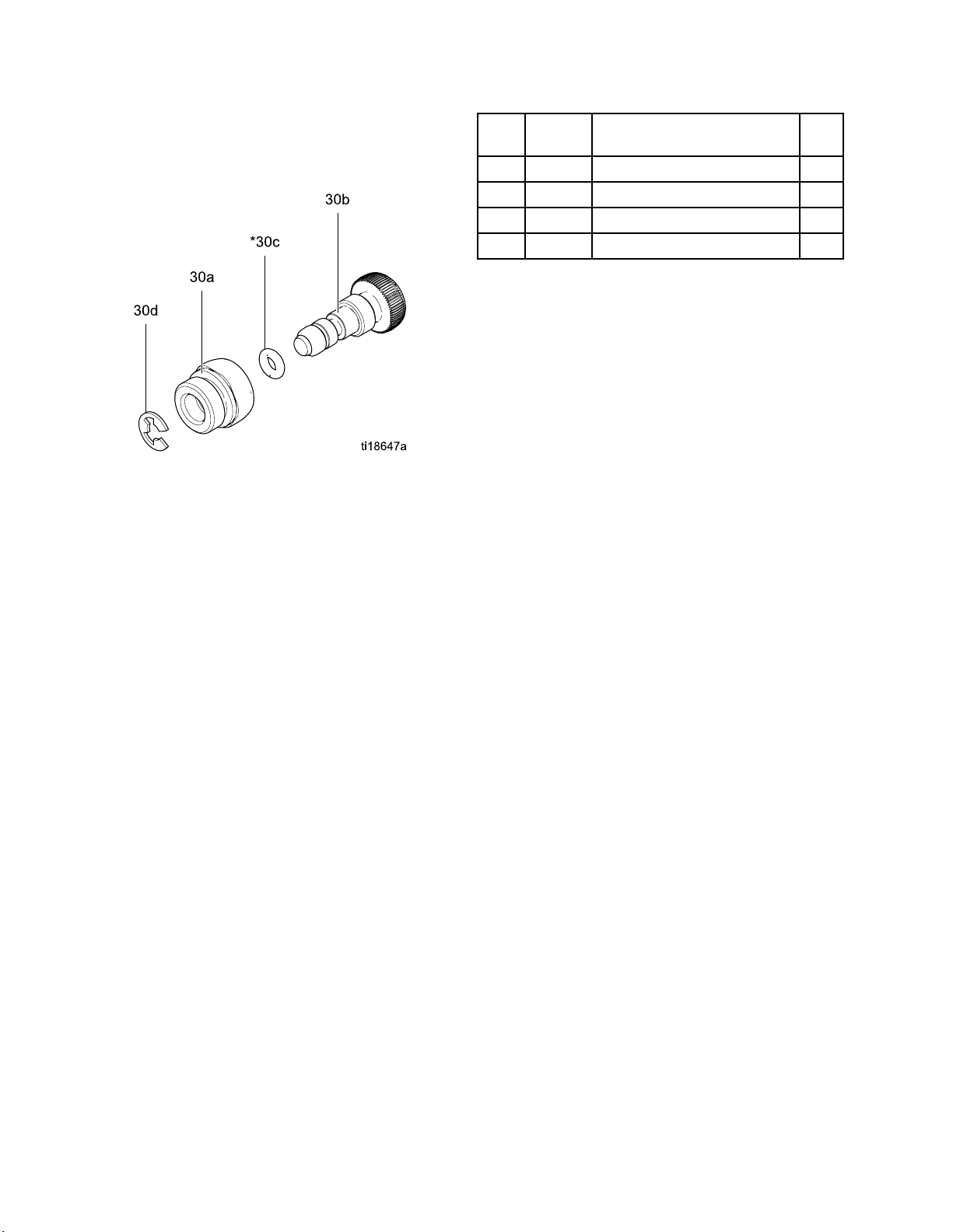
Parts
FanAirValveAssembly
Part No. 24N63
4 Fan Air Valve Assembly
Ref.
No.
30a
30b
30c*
30d 24N646
Part No. Description
———
———
111504
NUT, valve 1
STEM, valve
O-RING
RING, retaining; package of 6
Qty
1
1
1
* These parts are included in Air Seal Repair Kit
24N789 (purchase separately).
Parts labeled — — — are not available separately.
60 3A2495C
Page 61

Parts
Air Cap Assemb
ly
Part No. 24N727 Air Cap Assembly
Ref.
No.
25a 24N643
25b 24N734
25c
25d 24N726
Parts l
Part No. Description
ELECTRODE; package of 5
O-RING; ptfe; package of 5
(also available in package of
10; order 24E459)
———
AIR CAP
GUARD, tip, orange
abeled — — — are not available separately.
Qty
1
1
1
1
Smart Module A
ssembly
Part No. 24N756 Smart Module Assembly
Ref.
No.
31a
31b 24P433
31c 24N787
31d♦
31e♦
31f
Part No. Description
———
———
———
112319
CARTRIDGE
GASKET
SWITCH, ES HI/LO
SCREW
SCREW, pivot
O-RING
Qty
1
1
1
3
1
1
Parts labeled — — — are not available separately.
♦ThesepartsareincludedinSmartModuleScrew
Kit 24N757 (purchase separately).
3A2495C 61
Page 62

Spray Tip Select
ion Chart
Spray Tip Sele
AEM Fine Finis
Recommended for high finish quality applications at low and medium pressures. Order desired tip, Part No.
AEMxxx, where xxx = 3–digit number from the matrix below.
Orifice
Size
in.
(mm)
†0.007
(0.178)
†0.009
(0.229)
†0.011
(0.279)
0.013
(0.330
0.015
(0.381)
0.017
(0.432)
9
0.01
83)
(0.4
0.021
(0.533)
0.023
(0.584)
025
0.
0.635)
(
0.029
(0.736)
0.031
(0.787)
0.033
(0.838)
0.037
(0.939)
0.039
(0.990)
* Tips are tested in water.
Fluid Output
floz/min(l/min)
at 600
psi (4.1
MPa,
41 bar)
4.0
(0.1)
7.0
(0.2)
10.0
(0.3)
13.0
)
(0.4)
17.0
(0.5)
22.0
(0.7)
28.0
(0.8
35.0
(1.0)
40.0
(1.2)
.0
50
1.5)
(
68.0
(1.9)
78.0
(2.2)
88.0
(2.5)
108.0
(3.1)
118.0
(3.4)
h Spray Tips
at 1000
psi (7.0
MPa,
70 bar)
5.2
(0.15)
9.1
(0.27)
13.0
(0.4)
16.9
(0.5)
22.0
(0.7)
28.5
(0.85)
36.3
)
(1.0
45.4
(1.36)
51.9
(1.56)
64
1.94)
(
88.2
(2.65)
101.1
(3.03)
114.1
(3.42)
140.0
(4.20)
153.0
(4.59)
ction Chart
2–4
(50–
100)
107 207 307
9)
.8
Maximum Pattern Width at 12 in. (305 mm)
in. (mm)
4–6
(100–
150)
209 309 409 509 609
211 311 411 511 611 711
213 313 413 513 613 713 813
215 315 415 515 615 715 815
217 317 417 517 617 717
6-8
(150-
200)
319 419 519 619 719
8-10
(200-
250)
Spray Tip
421 521 621 721 821
423 523 623 723 823
42
431 631 831
10-12
(250-
300)
5
52
539
12-14
(300-
350)
5
62
14-16
(350-
400)
5
72
737
16-18
(400-
450)
5
82
829
833
5
Fluid output (Q) at other pressures (P) can be calculated by this formula: Q = (0.041) (QT) where QT =
fluid output (fl oz/min) at 600 psi from the above table for the selected orificesize.
† These tip sizes include a 150 mesh filter.
62 3A2495C
Page 63
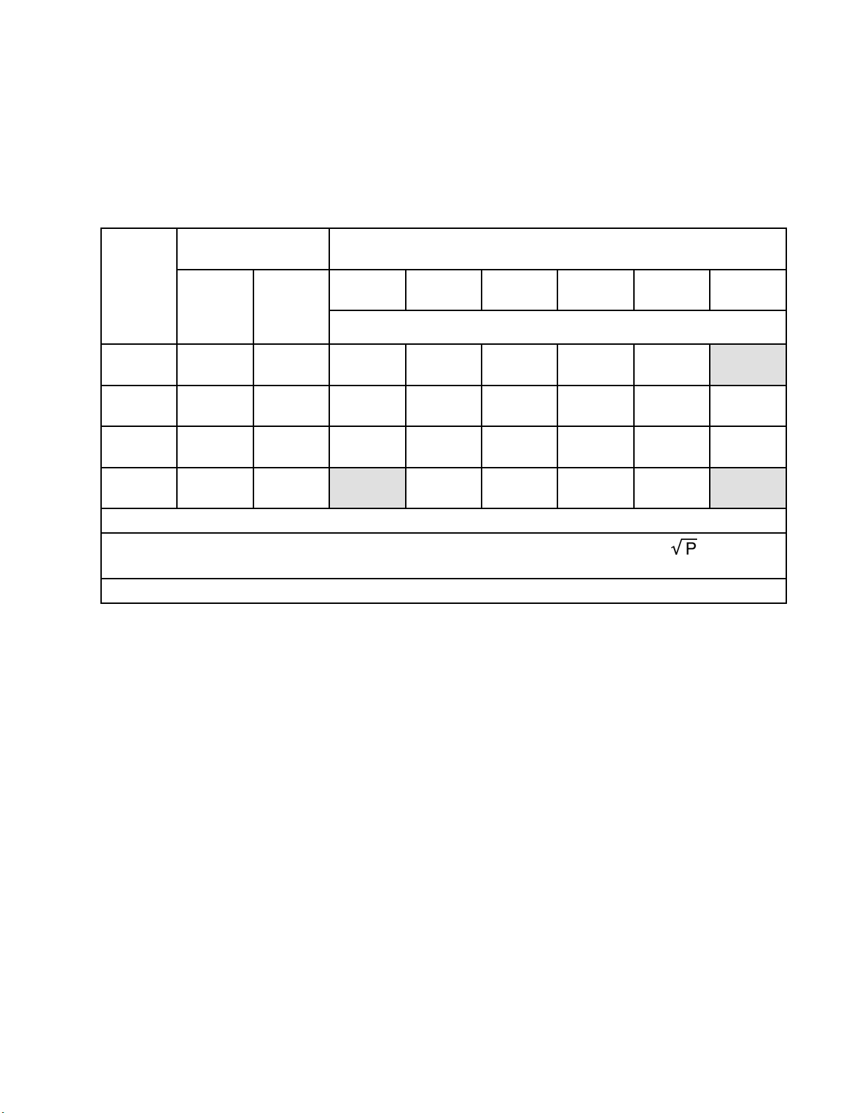
Spray Tip Select
ion Cha rt
AEF Fine Finis
h Pre-Orifice Spray
Tips
Recommended f
that assists
Order desired tip, Part No. AEFxxx, where xxx = 3–digit number from the matrix below.
Orifice
Size
in. (mm)
†0.010
(0.254)
0.012
(0.305)
0.014
(0.356)
0.016
(0.406)
or high finish quality applications at low and medium pressures. AEF tips have a pre-orifice
in atomizing sheer thinning materials, including lacquers.
Fluid Output
fl oz/min (l/min)
at 600 psi
(4.1 MPa,
41 bar)
9.5 (0.28
12.0
(0.35)
16.0
(0.47)
20.0
(0.59)
)
at 1000
psi (7.0
MPa, 70
bar) Spray Tip
12.5
(0.37)
16.0
(0.47)
21.0
(0.62)
26.5
(0.78)
6-8 (150-
200)
310 410 510 610 710
312 412 512 612 712 812
314 414 514 614 714 814
Maximum Pattern Width at 12 in. (305 mm)
in. (mm)
8-10
(200-250)
416 516 616 716
10-12
(250-300)
12-14
(300-350)
14-16
(350-400)
16-18
(400-450)
* Tips are tested in water.
Fluid output (Q) at other pressures (P) can be calculated by this formula: Q = (0.041) (QT) where QT =
fluid output (fl oz/min) at 600 psi from the above table for the selected orificesize.
† These tip sizes include a 150 mesh filter.
3A2495C 63
Page 64

Repair Kits, Rel
ated Manuals, and Accessories
Repair Kits, Related Manuals, and Accessories
Gun Part No.
All guns in thi
manual.
s
Gun Accessories
Part No. Description
105749
111265
116553
24N319
24N603
Cleaning Brush.
Non-silicone Lub
Dielectric Grease. 1 oz (30 ml)
Round Spray Kit. To convert a
standard air—assisted spray gun to
a round spray air cap. See manual
3A2499.
Gun Covers. Fo
guns. Box of 10
Description Manual Description Repair Kits Repair Kit
Description
60kVand85kV
Air-Assiste
Guns
d Spray
ricant, 4 oz (113 g).
r40kVand60kV
.
Electrostati
Air-Assiste
Spray Guns,
Instruction
c
d
s-Parts
24N789
24N706 Alternator Bearing
System Acces
Part No. Description
222011
16P802
16P798
16P799
24N528
24P312
Ground Wire
English Warning Sign. Available at
no charge from Graco.
English Daily Care Sign.
English
Gun Flush Box Adapter. To convert
existing gun flush boxes to hold Pro
Xp guns.
Gun Washer Kit. To convert existing
gun washers to clean Pro Xp guns.
Air Seal Repair Kit
Repair Kit
sories
and Clamp.
Setup Sign
24N604
24N642
24N758
24P170 Metal Trigger Kit.
24P172
185105
185493
112534
Gun Covers. For 85 kV guns. Box
of 10.
Ball Swivel, for gun air inlet. 1/4
npsm (left-hand thread)
Display Cov
clean. Pac
Quick Adj
change of
Non-swivel Air Inlet; 1/4–18 npsm(m)
(left-hand thread)
Air Hose Adapter; 1/4 npt(m) x
1/4–18 npsm(m) (left-hand thread)
Air Lin
ers. Keeps Smart display
kage of 5.
ust Valve. For quick
fan size.
e Quick Disconnect Fitting.
Test Equipment
Part No. Description
79
2410
722886
2860
72
245277 Test Fixture, High Voltage Probe,
hmmeter. 500 V output,
Mego
–2000 megohms. Use for
0.01
nd continuity and gun resistance
grou
s. Not for use in hazardous
test
as.
are
Paint Resistance Meter. Use for fluid
resistivity test. See manual 307263.
Not for use in hazardous areas.
Paint Probe. Use for fluid resistivity
test. See manual 307263. Not for
use in hazardous areas.
and kV Meter. Use to test the
electrostatic voltage of the gun, and
the condition of the alternator and
power supply when being serviced.
See manual 309455.
64 3A2495C
Page 65

Hoses
Repair Kits, Rel
ated Manuals, and Accessories
Grounded Air Hoses
100 psi (0.7 MPa, 7 bar) Maximum Working Pressure
0.315 in. (8 mm) ID; 1/4 npsm(f) x 1/4 npsm(f)
left-hand thread
Part No. Description
AirFlex Flexible Grounded Air Hose (Gray)
244963
244964
244965
244966
244967
244968
244969
Part No. Description
Standard Grounded Air Hose (Gray)
223068
223069
223070
223071
223072
6ft(1.8m)
15 ft (4.6 m)
25 ft (7.6 m)
36 ft (11 m)
50 ft (15 m)
75 ft (23 m)
100 ft (30.5 m)
6ft(1.8m)
15 ft (4.6 m)
25 ft (7.6 m)
36 ft (11 m)
50 ft (15 m)
Air Whip Hoses
100 psi (0.7 MPa, 7 bar) Maximum Working Pressure
0.188 in. (5 mm) ID; 1/4 npsm(m) x 1/4 npsm(f)
left-hand thread
Part No. Description
Air Whip Hose with stainless steel braid ground
path (Red)
236130
236131
Fluid Hoses
3ft(0.9m)
6ft(1.8m)
3300 psi (22.7 MPa, 227 bar) Maximum Working
Pressure
1/4 in. (6 mm) ID; 1/4 npsm(fbe); nylon.
Part No. Description
240793
240794
Fluid Whip Hoses
25 ft (7.6 m)
50 ft (15 m)
3200 psi (22 MPa, 220 bar) Maximum Working
Pressure
1/8 in. (3 mm) ID; 1/4 npsm(f) x 1/4 npt(m); nylon.
223073
223074
0.375 in. (10 mm) ID; 3/8 npsm(f) x 1/4 npsm(f)
left-hand thread
24A225
24A226
Part No. Description
Grounded Air Hose with stainless steel braid
ground path (Red)
235068
235069
235070
235071
235072
235073
235074
75 ft (23 m)
100 ft (30.5 m)
50 ft (15 m)
75 ft (23 m)
6ft(1.8m)
15 ft (4.6 m)
25 ft (7.6 m)
36 ft (11 m)
50 ft (15 m)
75 ft (23 m)
100 ft (30.5 m)
Part No. Description
236134
236135
3ft(0.9m)
6ft(1.8m)
Operator Accessories
Part No. Description
117823
117824
117825
24N520
24N521
Conductive Gloves, box of 12 (small)
Conductive Gloves, box of 12
(medium)
Conductive Gloves, box of 12 (large)
Comfort Grip. Snap-on grip
increases handle size to reduce
operator fatigue. Medium size.
Comfort Grip. Snap-on grip
increases handle size to reduce
operator fatigue. Large size.
3A2495C 65
Page 66
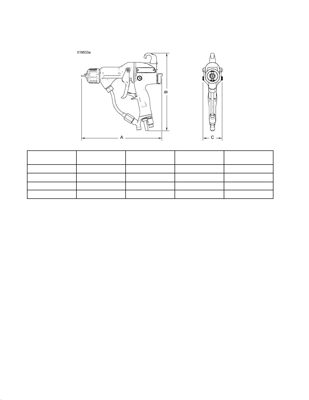
Dimensions
Dimensions
Figure 45
Gun Model A, in. (mm) B, in. (mm) C, in. (mm) Weight, oz (g)
H60T10
H85T10
H60M10
H85M10
9.7 (246) 9.1 (231) 2.4 (61) 23.2 (659)
10.7 (272) 9.2 (234) 2.4 (61) 25.8 (732)
9.8 (249) 9.9 (251) 2.4 (61) 25.7 (728)
10.8 (274) 9.9 (251) 2.4 (61) 28.3 (801)
66 3A2495C
Page 67

Technical Data
Technical Data
Electrostatic Air-Assisted Spray Guns
U.S.
Maximum Worki
Maximum Working Air Pressure 100 psi 0.7 MPa, 7.0 bar
Minimum Air Pressure at Gun Inlet
Maximum Fluid Operating
Temperature
Paint Resistivity Range
Air Inlet Fitting
Fluid Inlet Fitting
Output Voltage
Maximum Current Draw
Sound Power (measured per ISO
Standard 9216)
Sound
from g
Wett
Pressure (measured 1 m
un)
ed Parts
ng Fluid Pressure
3000 psi 21 MPa, 210 bar
45 psi 0.32 MPa, 3.2 bar
120°F 48°C
3 megohm/cm to infinity
1/4 npsm(m) left-hand thread
1/4–18 npsm(m)
ProXp60Models: 60kV
ProXp85Models: 85kV
125 microamperes
at 40 psi: 88.9 dB(A)
at 100
at 100 psi: 95.0 dB(A)
PEEK
psi: 99.7 dB(A)
at 40 p
si: 86.0 dB(A)
, UHMWPE, FEP, PTFE, acetal, nylon, polyethylene
at 0.28 MPa, 2.8 bar: 88.9 dB(A)
at 0.7
8 MPa, 2.8 bar: 86.0 dB(A)
at 0.2
at 0.7 MPa, 7.0 bar: 95.0 dB(A)
Metric
MPa, 7.0 bar: 99.7 dB(A)
3A2495C 67
Page 68

Graco Pro Xp Warranty
Graco warrants all equipment referenced in this document which is manufacturedbyGracoandbearingitsnametobe
free from defects in material and workmanship on the date of sale to the original purchaser for use. With the exception of
any special, extended, or limited warranty published by Graco, Graco will,foraperiodoftwelvemonthsfromthedate
of sale, repair or replace any part of the equipment determined by Graco to be defective. However, any deficiency in
the barrel, handle, trigger, hook, internal power supply, and alternator (excluding turbine bearings) will be repaired or
replaced for thirty-six months from the date of sale. This warranty applies only when the equipment is installed, operated
and maintained in accordance with Graco’s written recommendations.
This warranty does not cover, and Graco shall not be liable for general wear and tear, or any malfunction, damage or
wear caused by faulty installation, misapplication, abrasion, corrosion, inadequate or improper maintenance, negligence,
accident, tampering, or substitution of non-Graco component parts. Nor shall Graco be liable for malfunction, damage
or wear caused by the incompatibility of Graco equipment with structures, accessories, equipment or materials not
supplied by Graco, or the improper design, manufacture, installation, operation or maintenance of structures, accessories,
equipment or materials not supplied by Graco.
This warranty is conditioned upon the prepaid return of the equipment claimed to be defective to an authorized Graco
distributor for verification of the claimed defect. If the claimed defect is verified, Graco will repair or replace free of charge
any defective parts. The equipment will be returned to the original purchaser transportation prepaid. If inspection of the
equipment does not disclose any defect in material or workmanship, repairs will be made at a reasonable charge, which
charges may include the costs of parts, labor, and transportation.
THIS WARRANTY IS EXCLUSIVE, AND IS IN LIEU OF ANY OTHER WARRANTIES, EXPRESS OR IMPLIED,
INCLUDING BUT NOT LIMITED TO WARRANTY OF MERCHANTABILITY OR WARRANTY OF FITNESS FOR A
PARTICULAR PURPOSE.
Graco’s sole obligation and buyer’s sole remedy for any breach of warranty shall be as set forth above. The buyer agrees
that no other remedy (including, but not limited to, incidental or consequential damages for lost profits, lost sales, injury to
person or property, or any other incidental or consequential loss) shall be available. Any action for breach of warranty
must be brought within two (2) years of the date of sale.
GRACO MAKES NO WARRANTY, AND DISCLAIMS ALL IMPLIED WARRANTIES OF MERCHANTABILITY AND
FITNESS FOR A PARTICULAR PURPOSE, IN CONNECTION WITH ACCESSORIES, EQUIPMENT, MATERIALS OR
COMPONENTS SOLD BUT NOT MANUFACTURED BY GRACO. These items sold, but not manufactured by Graco
(such as electric motors, switches, hose, etc.), are subject to the warranty, if any, of their manufacturer. Graco will provide
purchaser with reasonable assistance in making any claim for breach of these warranties.
In no event will Graco be liable for indirect, incidental, special or consequential damages resulting from Graco supplying
equipment hereunder, or the furnishing, performance, or use of any products or other goods sold hereto, whether due to a
breach of contract, breach of warranty, the negligence of Graco, or otherwise.
FOR GRACO CANADA CUSTOMERS
The Parties acknowledge that they have required that the present document, as well as all documents, notices and legal
proceedings entered into, given or instituted pursuant hereto or relating directly or indirectly hereto, be drawn up in
English. Les parties reconnaissent avoir convenu que la rédaction du présente document sera en Anglais, ainsi que
tous documents, avis et procédures judiciaires exécutés, donnés ou intentés, à la suite de ou en rapport, directement ou
indirectement, avec les procédures concernées.
Graco Information
For the latest information about Graco products, visit www.graco.com.
To place an order, contact your Graco Distributor or call to identify the nearest distributor.
Phone: 612-623-6921 or Toll Free: 1-800-328-0211 Fax: 612-378-3505
All written and visual data contained in this document reflects the latest product information available at the time of publication.
Graco reserves the right to make changes at any time without notice.
For patent information, see www.graco.com/patents.
Original Instructions. This manual contains English, MM 3A2495
Graco Headquarters: Minneapolis
International Offices: Belgium, China, Japan, Korea
GRACO INC. AND SUBSIDIARIES • P.O. BOX 1441 • MINNEAPOLIS, MN 55440-1441 • USA
Copyright 2012, Graco Inc. All Graco manufacturing locations are registered to ISO 9001.
www.graco.com
Revised July 2013
 Loading...