

Page 1

Instructions - Parts
™
InvisiPac
™
HM25 Tank-Free
3A2347T
Hot Melt Delivery System
For delivering and dispensing hot melt adhesive pellets. For professional use only.
Not approved for use in explosive atmospheres or hazardous locations.
1200 psi (8.3 MPa, 83 bar) Maximum Working Pressure
400°F (204°C) Maximum Fluid Operating Temperature
100 psi (0.7 MPa,7 bar) Maximum Air Inlet Pressure
Important Safety Instructions
Read all warnings and instructions in this
manual and in the gun and hose manuals.
Save all instructions.
EN
ti20440b
9902471
Certified to
CAN/CSA C22.2 No. 88
Conforms to
ANSI/UL 499
Page 2

Contents
Related Manuals . . . . . . . . . . . . . . . . . . . . . . . . . . . 3
Required Tools . . . . . . . . . . . . . . . . . . . . . . . . . . . . 3
Models . . . . . . . . . . . . . . . . . . . . . . . . . . . . . . . . . . 4
Warnings . . . . . . . . . . . . . . . . . . . . . . . . . . . . . . . . . 5
Component Identification . . . . . . . . . . . . . . . . . . . . 8
Setup . . . . . . . . . . . . . . . . . . . . . . . . . . . . . . . . . . . . 14
Grounding . . . . . . . . . . . . . . . . . . . . . . . . . . . . . 14
Location . . . . . . . . . . . . . . . . . . . . . . . . . . . . . . 14
Attach Components . . . . . . . . . . . . . . . . . . . . . 14
Recommended Air Setup . . . . . . . . . . . . . . . . . 18
Connect Electrical Cord . . . . . . . . . . . . . . . . . . 19
480V Electrical Circuits . . . . . . . . . . . . . . . . . . . 21
208V Electrical Circuits . . . . . . . . . . . . . . . . . . . 21
Select ADM Settings . . . . . . . . . . . . . . . . . . . . . 21
Guns . . . . . . . . . . . . . . . . . . . . . . . . . . . . . . . . . 23
PLC Connection . . . . . . . . . . . . . . . . . . . . . . . . 24
Operation . . . . . . . . . . . . . . . . . . . . . . . . . . . . . . . . 26
Overview . . . . . . . . . . . . . . . . . . . . . . . . . . . . . . 26
Initial Startup and Prime . . . . . . . . . . . . . . . . . . 26
Manual Refill . . . . . . . . . . . . . . . . . . . . . . . . . . . 27
Automatic Refill . . . . . . . . . . . . . . . . . . . . . . . . . 28
Dispense . . . . . . . . . . . . . . . . . . . . . . . . . . . . . . 28
Shutdown . . . . . . . . . . . . . . . . . . . . . . . . . . . . . 29
Schedule . . . . . . . . . . . . . . . . . . . . . . . . . . . . . . 29
Pressure Relief Procedure . . . . . . . . . . . . . . . . 30
Drain the System . . . . . . . . . . . . . . . . . . . . . . . 30
Flush . . . . . . . . . . . . . . . . . . . . . . . . . . . . . . . . . 31
Operation Tips to Minimize Charring . . . . . . . . 33
Maintenance . . . . . . . . . . . . . . . . . . . . . . . . . . . . . . 34
Replace Outlet Filter . . . . . . . . . . . . . . . . . . . . . 34
Replace Inlet Filter . . . . . . . . . . . . . . . . . . . . . . 34
Replace Funnel Filter . . . . . . . . . . . . . . . . . . . . 35
Filter Maintenance Guidelines* . . . . . . . . . . . . . 36
Troubleshooting . . . . . . . . . . . . . . . . . . . . . . . . . . 37
ADM Error Code Table . . . . . . . . . . . . . . . . . . . 37
MZLP Troubleshooting . . . . . . . . . . . . . . . . . . . 50
Repair . . . . . . . . . . . . . . . . . . . . . . . . . . . . . . . . . . . 51
Pump . . . . . . . . . . . . . . . . . . . . . . . . . . . . . . . . . 51
Melter . . . . . . . . . . . . . . . . . . . . . . . . . . . . . . . . . 55
Multi-Zone Low Power Temperature Control Module
(MZLP) . . . . . . . . . . . . . . . . . . . . . . . . . . . . 62
System . . . . . . . . . . . . . . . . . . . . . . . . . . . . . . . . 64
Air Controls . . . . . . . . . . . . . . . . . . . . . . . . . . . . 66
Air Motor . . . . . . . . . . . . . . . . . . . . . . . . . . . . . . 67
Software Update Procedure . . . . . . . . . . . . . . . 71
Electrical Schematics . . . . . . . . . . . . . . . . . . . . . . 72
Incoming Power and Terminal Jumpers . . . . . . 72
Parts . . . . . . . . . . . . . . . . . . . . . . . . . . . . . . . . . . . . 76
Accessories . . . . . . . . . . . . . . . . . . . . . . . . . . . . . . 89
Non-Graco Gun Adapter Cables . . . . . . . . . . . . 90
Air Adjustment Lock, 24R084 . . . . . . . . . . . . . . 90
System Stand, 24R088 . . . . . . . . . . . . . . . . . . . 91
Caster for Stand, 120302 . . . . . . . . . . . . . . . . . 91
Adapter Plate, 24R083 . . . . . . . . . . . . . . . . . . . 91
30 Gallon Vibrating Hopper, 24R136 . . . . . . . . . 92
Light Tower Kit, 24R226 . . . . . . . . . . . . . . . . . . 94
Air Reservoir Kit, 16W366 . . . . . . . . . . . . . . . . . 95
Air Metric Fitting Kit, 24W637 . . . . . . . . . . . . . 103
Appendix A - ADM . . . . . . . . . . . . . . . . . . . . . . . . 104
General Operation . . . . . . . . . . . . . . . . . . . . . . 104
Icon Identification . . . . . . . . . . . . . . . . . . . . . . . 104
Appendix B - USB Downloading, Uploading . . . 110
Download Procedure . . . . . . . . . . . . . . . . . . . . 110
Accessing Files . . . . . . . . . . . . . . . . . . . . . . . . 110
Upload Procedure . . . . . . . . . . . . . . . . . . . . . . 110
USB Logs . . . . . . . . . . . . . . . . . . . . . . . . . . . . 111
System Settings File . . . . . . . . . . . . . . . . . . . . 111
System Language File . . . . . . . . . . . . . . . . . . . 112
Technical Data . . . . . . . . . . . . . . . . . . . . . . . . . . . 113
Dimensions . . . . . . . . . . . . . . . . . . . . . . . . . . . 117
Graco Extended Warranty . . . . . . . . . . . . . . . . . . 120
Graco Information . . . . . . . . . . . . . . . . . . . . . . . . 120
2 3A2347T
Page 3

Related Manuals
Manuals are available at www.graco.com. Component
manuals in English:
Part Description
3A2805 InvisiPac GS35 Hot Melt Gun Instructions -
Parts
332072 InvisiPac Heated Hose Instructions - Parts
Required Tools
Related Manuals
• Standard allen wrench set
• Metric allen wrench set
• Various sizes of crescent wrenches
• 11/16 in. wrench
• 3/8 in. ratchet
• 3/8 in. socket
• 5/16 in. driver
• 7/16 in. socket
• 7/8 in. deep well socket
• 1 in. socket
• 13 mm socket
• 10 mm socket
• 1/2 in. ratchet
• Side cutter
• Phillips head screwdriver
• Flat head screwdriver
• Multimeter
• Tubing cutter
3A2347T 3
Page 4

Models
Models
NOTICE
To prevent system damage, verify terminal jumpers
are installed correctly before applying power.
Model Channels Voltage
24P260 2 200-240VAC
24P261 4 200-240VAC
24P262 2 350-415VAC Y
24P263 4 350-415VAC Y
24P264 2
24P265 4
24U132 6 200-240VAC
24U133 6 350-415VAC Y
24U134 6
200-240VAC
200-240VAC
200-240VAC
Δ
Δ
Δ
Φ
1
Φ
/ PE
Φ
/ PE
1
Φ
/ Neutral / PE
3
3
Φ
/ Neutral / PE
3Φ / PE
3Φ / PE
1
Φ
/ PE
Φ
/ Neutral / PE
3
3Φ / PE
Type Description Frequency
•1-Phase
• 200-240VAC
• 2 wire and PE
• 3-Phase with Neutral
• 350-415 VAC Line to
Line
• 200-240VAC Line to
Neutral
• 3 wire and Neutral and
PE
• 3-Phase without
Neutral
• 200-240 VAC Line to
Line
• 3 wire and PE
•1-Phase
• 200-240VAC
• 2 wire and PE
• 3-Phase with Neutral
• 350-415 VAC Line to
Line
• 200-240VAC Line to
Neutral
• 3 wire and Neutral and
PE
• 3-Phase without
Neutral
• 200-240 VAC Line to
Line
• 3 wire and PE
50/60 Hz 32A
50/60 Hz 40A
50/60 Hz 16A
50/60 Hz 16A
50/60 Hz 27A
50/60 Hz 27A
50/60 Hz 40A
50/60 Hz 30A
50/60 Hz 40A
Max
Amps
4 3A2347T
Page 5

Warnings
Warnings
The following warnings are for the setup, use, grounding, maintenance, and repair of this equipment. The exclamation point symbol alerts you to a general warning and the hazard symbols refer to procedure-specific risks. When
these symbols appear in the body of this manual or on warning labels, refer back to these Warnings. Product-specific
hazard symbols and warnings not covered in this section may appear throughout the body of this manual where
applicable.
WARNING
ELECTRIC SHOCK HAZARD
This equipment must be grounded. Improper grounding, setup, or usage of the system can cause
electric shock.
• Turn off and disconnect power at main switch before disconnecting any cables and before servicing
or installing equipment.
• Connect only to grounded power source.
• All electrical wiring must be done by a qualified electrician and comply with all local codes and
regulations.
BURN HAZARD
Equipment surfaces and fluid that’s heated can become very hot during operation. To avoid severe
burns:
• Do not touch hot fluid or equipment.
SKIN INJECTION HAZARD
High-pressure fluid from dispensing device, hose leaks, or ruptured components will pierce skin. This
may look like just a cut, but it is a serious injury that can result in amputation. Get immediate surgical
treatment.
+
• Do not point dispensing device at anyone or at any part of the body.
• Do not put your hand over the fluid outlet.
• Do not stop or deflect leaks with your hand, body, glove, or rag.
•Follow the Pressure Relief Procedure when you stop dispensing and before cleaning, checking, or
servicing equipment.
• Tighten all fluid connections before operating the equipment.
• Check hoses and couplings daily. Replace worn or damaged parts immediately.
MOVING PARTS HAZARD
Moving parts can pinch, cut or amputate fingers and other body parts.
• Keep clear of moving parts.
• Do not operate equipment with protective guards or covers removed.
• Pressurized equipment can start without warning. Before checking, moving, or servicing equipment,
follow the Pressure Relief Procedure and disconnect all power sources.
3A2347T 5
Page 6

Warnings
WARNING
EQUIPMENT MISUSE HAZARD
Misuse can cause death or serious injury.
• Do not operate the unit when fatigued or under the influence of drugs or alcohol.
• Do not exceed the maximum working pressure or temperature rating of the lowest rated system
component. See Technical Data in all equipment manuals.
• Use fluids and solvents that are compatible with equipment wetted parts. See Technical Data in all
equipment manuals. Read fluid and solvent manufacturer’s warnings. For complete information
about your material, request MSDS from distributor or retailer.
• Do not leave the work area while equipment is energized or under pressure.
• Turn off all equipment and follow the Pressure Relief Procedure when equipment is not in use.
• Check equipment daily. Repair or replace worn or damaged parts immediately with genuine manufacturer’s replacement parts only.
• Do not alter or modify equipment. Alterations or modifications may void agency approvals and create
safety hazards.
• Make sure all equipment is rated and approved for the environment in which you are using it.
• Use equipment only for its intended purpose. Call your distributor for information.
• Route hoses and cables away from traffic areas, sharp edges, moving parts, and hot surfaces.
• Do not kink or over bend hoses or use hoses to pull equipment.
• Keep children and animals away from work area.
• Comply with all applicable safety regulations.
FIRE AND EXPLOSION HAZARD
Flammable fumes, such as solvent and paint fumes, in work area can ignite or explode. To help prevent
fire and explosion:
• Do not use solvent-based adhesives that can create an explosive atmosphere when processed.
• Use equipment only in well ventilated area.
• Eliminate all ignition sources; such as pilot lights, cigarettes, portable electric lamps, and plastic drop
cloths (potential static arc).
• Keep work area free of debris, including solvent, rags and gasoline.
• Do not plug or unplug power cords, or turn power or light switches on or off when flammable fumes
are present.
• Ground all equipment in the work area. See Grounding instructions.
• Use only grounded hoses.
• Stop operation immediately if static sparking occurs or you feel a shock. Do not use equipment
until you identify and correct the problem.
• Keep a working fire extinguisher in the work area.
TOXIC FLUID OR FUMES HAZARD
Toxic fluids or fumes can cause serious injury or death if splashed in the eyes or on skin, inhaled, or
swallowed.
• Read MSDSs to know the specific hazards of the fluids you are using.
• Store hazardous fluid in approved containers, and dispose of it according to applicable guidelines.
6 3A2347T
Page 7

Warnings
WARNING
PERSONAL PROTECTIVE EQUIPMENT
Wear appropriate protective equipment when in the work area to help prevent serious injury, including
eye injury, hearing loss, inhalation of toxic fumes, and burns. This protective equipment includes but is
not limited to:
• Protective eyewear, and hearing protection.
• Respirators, protective clothing, and gloves as recommended by the fluid and solvent manufacturer
PRESSURIZED ALUMINUM PARTS HAZARD
Use of fluids that are incompatible with aluminum in pressurized equipment can cause serious chemical
reaction and equipment rupture. Failure to follow this warning can result in death, serious injury, or property damage.
• Do not use 1,1,1-trichloroethane, methylene chloride, other halogenated hydrocarbon solvents or
fluids containing such solvents.
• Many other fluids may contain chemicals that can react with aluminum. Contact your material supplier for compatibility.
3A2347T 7
Page 8

Component Identification
Component Identification
G3
G2
G4
A
G
G1
H
F
E
C
D
B
K
L
Key:
A Advanced Display Module (ADM)
B Electrical Enclosure
C Pump Air Pressure Regulator
D Pump Air Pressure Gauge
E Vacuum Transfer Air Pressure Regulator
F Vacuum Transfer Air Pressure Gauge
GShaker Tube
G1 Shaker Head
G2 Vacuum Transfer Tube
G3 Vacuum Transfer Inlet Funnel
G4 Vacuum Transfer 3/8 in. OD Air Supply
H Main Power Switch
J System Air Inlet
K Vacuum Transfer (Shaker) Inlet
L Air Motor and Pump
M Incoming Power Strain Relief
N Heated Fluid Manifold (Melter)
P Multi-Zone Low Power Temperature Control Module (MZLP)
R Fluid Outlets for connection to Heated Hoses (numbered 1-4)
S Customer I/O Cable (optional)
R
P
ti20441b
N
M
S
J
FIG. 1
8 3A2347T
Page 9

Heated Fluid Manifold
AB
Z
U
X
T
Component Identification
Y
R
AA
NOTE: System shown with plastic and metal shrouds removed.
FIG. 2
Key:
T Electrical Enclosure Front Access Door
UMelter
W1 Drain Port
W2 Drain Tray
X Inlet Filter (Low Pressure - Before Pump)
Y Outlet Filter (High Pressure - After Pump)
W1
W2
ti20442b
Z Adhesive Pellets Level Sensor
AA Power and RTD Harness Connection to Heated Hose and
Gun (harness connects from system to heated hose then
from heated hose to gun)
AB Inlet Funnel Screen
3A2347T 9
Page 10

Component Identification
Electrical Enclosure
AC
AJ
FIG. 3
Key:
P Multi-Zone Low Power Temperature Control Module
(MZLP)
AC Incoming Power Connection
AF Chassis Ground
P
ti20907b
AH
AG
AF
AG Terminal Blocks and Jumpers
AH Heater Relay
AJ Incoming Power Terminal Jumpers. See page 19.
10 3A2347T
Page 11

Advanced Display Module (ADM)
Component Identification
User Interface
NOTICE
To prevent damage to soft key buttons, do not press
the buttons with sharp objects such as pens, plastic
cards, or fingernails.
NOTE: See Appendix A - ADM on page 104 for complete ADM operation details.
BB
BC
BA
BD
BE
BF
B
Ke
yFunction
BA Heating system and pump enable/disable
BB System status indicator (LED)
BC Stop all system processes
BD Defined by icon next to softkey
BE Abort current operation
BF Accept change, acknowledge error, select item,
toggle selected item
BG Toggle between Operation and Setup screens
BH Navigate within a screen or to a new screen
BK
BL
BH
FIG. 4
BG
TI12362a1
BR
BM
BN
BP
FIG. 5
Key:
BK Part Number Identification Label
BL USB Interface
BM CAN Cable Connection (Power Supply and Communica-
tion)
BN Module Status LEDs
BP (Not used)
BR Software Token Access Panel
3A2347T 11
Page 12

Component Identification
Screen Components
Current date and time
Operating Mode
Hose and Gun
Heating Status
Hose Actual Temperature
FIG. 6: Main Screen Components
Operating Mode Description Component Status
System Off
Inactive
Warm Up
Active
The system doesn’t have power.
The heating system and pumps are
disabled.
The system is increasing the material
to the set temperature.
The system is ready to dispense
material.
Screens Order
Gun Actual Temperature
• No System Status Indicator LED on the
ADM
• No heat
• Pump is off
• Yellow system status indicator LED on the
ADM
• No heat
• Pump is off (manually changed)
• Flashing green system status indicator LED
on the ADM
• Heat is increasing to setpoint temperature
• Pump is off
• Solid green system status indicator LED on
the ADM
• Heat is at setpoint temperature
• Pump is on
Faults, Status
Melter Heating Status
Melter Actual Temperature
12 3A2347T
Page 13

Component Identification
3A2347T 13
Page 14

Setup
Setup
Grounding
The equipment must be grounded to reduce the risk
of electric shock. Improper grounding can cause
electric shock. Grounding provides an escape wire
for the electric current.
The InvisiPac system is equipped with a ground terminal. Have a qualified electrician ground the system
using this terminal. See Connect Electrical Cord on
page 19.
Location
Ambient temperature must be 32-120°F (0-49°C).
The supplied vacuum transfer hose length is 10 ft (3 m).
The maximum vacuum transfer hose length available is
30 ft (9.1 m). The adhesive pellets container must be
located within reach of the vacuum transfer hose and no
more than 30 ft (9.1 m).
Attach Components
To reduce the risk of electric shock, do not connect
electrical cord until after this Attach Components
procedure is complete.
1. Place the base system in the desired operating
location and orientation. See Location on this page.
• The bottom of the electrical enclosure has holes for
securing the InvisiPac system to a surface. The
holes are accessible through the bottom access
doors in the three rear walls of the electrical enclosure.
• To install the InvisiPac system in place of a
non-Graco hot melt system, purchase Adapter
Plate, 24R083. See installation instructions on
page 91.
The gun(s) must be located no more than 25 ft (7.6 m)
from the melter.
Place the base system on a surface that is eye-level for
easiest operation. Use System Stand, 24R088, to
install system at eye-level. See page 91.
If installing the system in place of a non-Graco hot melt
system, purchase Adapter Plate, 24R083. See
page 91.
Optional 30 Gallon Vibrating Hopper, 24R136, available (purchase separately). See page 92.
To make repairing the system easier, locate the system
so that all sides are easily accessible and have sufficient
lighting.
• To raise the system to eye-level, purchase System
Stand, 24R088. See installation instructions on
page 91.
NOTE: Supplied vacuum transfer hose must reach from
the system to the adhesive pellets container. Supplied
heated hose must reach from system to gun(s).
2. Install vacuum transfer inlet funnel (G3) onto system. See F
a. Slide funnel through the bracket connected to
the air motor.
b. Position the funnel so the funnel inlet faces the
desired direction.
c. Connect 5/32 in. OD air line to funnel.
IG
. 7.
14 3A2347T
Page 15

Setup
d. Install supplied hose clamp around the air motor
bracket and funnel base then tighten.
G2
G3
G4
ti21130b
FIG. 7
3. Insert 1.3 in. (33 mm) OD clear vacuum transfer
hose (G2) into vacuum transfer funnel (G3) inlet and
secure with supplied hose clamp. See F
IG
. 7.
6. Apply pipe sealant to threads then attach steel
shaker tube (G) to shaker head (G1). See F
IG
. 8.
NOTICE
To prevent shaker head (G1) galling to the shaker
tube (G), do not overtighten shaker head onto shaker
tube. These should be hand-tightened.
G2
G6
G5
G
G4
4. Connect the long supplied 3/8 in. OD air line (G4) to
the 3/8 in. push-to-connect fitting on the air line from
the system. See F
IG
. 7.
NOTE: In the following steps, when routing the vacuum
transfer hose, ensure there are no tight coils, turns, or
dips in the vacuum hose. These will inhibit optimal functioning of the vacuum transfer system.
NOTE: Maximum vacuum hose length is 30 ft (9.1 m).
Use horizontal hose routing as much as possible. The
vacuum hose must not rise more than 10 ft (3.0 m),
measured from the vacuum inlet. Any vertical rise will
lower the maximum flow rate of the vacuum transfer
system.
5. Route the 1.3 in. (33 mm) OD clear vacuum transfer
hose from the system to the adhesive pellets container location.
G1
ti21131a
FIG. 8
7. Attach 1.3 in. (33 mm) clear vacuum transfer hose
(G2) to steel shaker tube (G) and secure with supplied hose clamp. See F
IG
. 8.
8. Route the 3/8 in. OD air line (G4) alongside the
1.3 in. (33 mm) clear vacuum transfer hose (G2)
and secure at multiple points with the supplied zip
ties (G5). See F
IG
. 8.
9. If desired, secure the 1.3 in. (33 mm) clear vacuum
transfer tube and 3/8 in. OD air line with zip ties to a
supporting structure at various points in the routing.
10. Attach the other end of the long 3/8 in. OD air line
(G4) to the 3/8 in. push-to-connect fitting on the
shaker head (G1).
11. Ensure the adhesive pellets container is in the
desired operating location. The location should be
chosen to make it easy to fill the container with pellets.
3A2347T 15
Page 16

Setup
12. Place shaker assembly in an empty adhesive pellets container then fill the container with adhesive
pellets.
NOTE: To promote optimal system performance, purchase 30 Gallon Vibrating Hopper, 24R136. See
installation instructions on page 92.
NOTE: If static buildup on feed tube (G) is excessive,
install optional feed tube ground kit 24R708 to feed tube
end (G6). See F
13. Install heated hoses, see F
IG
. 8.
IG
. 9:
To reduce the risk of fire and explosion, only use
Graco heated hoses with the InvisiPac system. Use
of non-Graco hoses will void agency approvals.
N
247
Gun
68
d. Remove plug (247) from the lowest numbered
outlet on the melter. Do not use the drain
plug (W1). See F
IG
. 9.
NOTE: In the following step, the o-ring side of the
hydraulic fitting (68) faces the system. See F
IG
. 9.
e. Install the supplied hydraulic fitting (68) with an
o-ring into the open port and tighten with an
11/16 in. wrench or socket.
f. Install hose onto hydraulic fitting (68) with male
electrical connector side toward the system.
Use 11/16 in. wrench to tighten hose onto
hydraulic fitting (68).
g. Locate MZLP (AA) connector marked with same
number as the hose fluid outlet port. Remove
that connector cover then install connector from
heated hose. See F
IG
. 9.
h. Repeat the procedure for the remaining chan-
nels. Use the bottom melter ports first to ease
installation.
W1
W2
AA
ti21132a
FIG. 9
a. Place a rag on the drain tray (W2) attached to
the melter. Residual oil may be in the system
from the factory. See F
IG
. 9.
b. Use a 1/4 in. allen wrench to remove the drain
IG
port plug (W1). See F
. 9.
NOTE: A 1/4 in. allen wrench is shipped loose with the
system.
c. When fluid stops draining, re-install drain port
IG
plug (W1) then remove rag. See F
. 9.
i. Install cap on any unused MZLP electrical con-
nectors.
NOTE: Fluid outlet port 1 must be used and electrical
connector from that hose must be connected to MZLP
connector 1. The system will not operate unless a hose
is connected to MZLP connector 1. If a hose is not connected to connector 1, “Invalid Sensor - hose/gun” faults
will result.
14. Install gun(s), see F
IG
. 9:
NOTE: Use of a Graco gun is not required with this system. However, all guns attached to the system must be
rated for 1200 psi (8.3 MPa, 83 bar), 400°F (204°C),
have an RTD type sensor, and use no more than 400W.
a. Connect heated hose fluid outlet to gun fluid
inlet. Use 11/16 in. wrench to tighten. See F
IG
.
9.
b. For Graco guns, attach gun electrical connector
IG
to heated hose electrical connector. See F
. 9.
16 3A2347T
Page 17

Setup
c. For non-Graco guns, attach gun electrical con-
nector to adapter harness (16T916, 16T917, or
16Y828) then attach adapter harness connector
to heated hose connector. See Non-Graco
Gun Adapter Cables on page 90 to determine
which adapter cable to use with your valve.
d. Repeat for any additional guns.
15. If necessary, set up the valve controller to control
opening and close the gun. See gun manual.
NOTE: The system controls gun heating only. A separate gun controller must be set up to open and close the
guns.
16. Install the supplied air inlet bleeding ball valve and
air filter kit (Graco Part No. 24R707) at the 1/4 NPT
female system air inlet (J). See F
IG
. 10.
17. If using the same air for the gun(s), make sure to
install the tee in the air line before the ball valve.
There should not be anything between the ball valve
and the system. See gun manual for gun air pressure requirements, and use a regulator before the
gun to decrease the air pressure, if necessary.
18. Close the ball valve.
WLE
ti21147a
FIG. 11
19. Attach a 3/8 in. minimum air supply line to air filter.
See F
IG
. 11.
J
WLE
ti21133a
FIG. 10
NOTE: The system must have a bleed-type ball valve
that bleeds pressure downstream when closed. Otherwise, the supplied air will need to be disconnected from
the system whenever the pressure is relieved.
NOTE: The system must use an air filter with a minimum flow rate of 30 scfm.
NOTE: Air supply pressure must be between 80 psi
(550 kPa, 5.5 bar) and 100 psi (690 kPa, 6.9 bar). Recommended pressure is 100 psi (690 kPa, 6.9 bar). If air
pressure is expected to drop below 80 psi (0.5 MPa,
5 bar), there is an air reservoir kit that allows the system
to operate down to 60 psi (0.4 MPa, 4 bar). See Air
Reservoir Kit, 16W366, on page 95.
20. To lock access to the air pressure adjustments, purchase Air Adjustment Lock, 24R084. See installation instructions on page 90.
21. To install a light tower that illuminates red when a
system error occurs, purchase Light Tower Kit,
24R226. See installation instructions on page 94.
22. To upgrade a 2 channel system to a 4 channel system, purchase 4 Channel Upgrade Kit, 24R237.
See installation instructions on page 96.
23. Install MZLP electrical connector caps on all unused
channels.
3A2347T 17
Page 18

Setup
Recommended Air Setup
Main Air Line
Air In:
Less than 50 ft (15.2 m): 3/8 in.
More than 50 ft (15.2 m): 1/2 in.
80-100 psi
(5.5-6.8 bar, 0.55-6.8 MPa)
30 scfm capacity.
Air Filter/Ball Valve at
System Air Inlet
(Graco Kit 24R707,
included)
Vacuum:
40 - 80 psi
(2.8-5.5 bar,
0.28-0.55 MPa);
and at least 65% of
hopper shaker air
pressure, if used
No dips in vacuum
transfer hose
Ensure funnel air
is connected
Pump:
20-100 psi
(1.4-6.8 bar,
0.14-0.68 MPa)
Air In:
3/8 in.,
100 psi
(6.8 bar, 0.68 MPa),
30 scfm capacity
WLE
Air to guns
Regulator set to
70 psi
(4.8 bar, 0.48 MPa)
FIG. 12
18 3A2347T
Page 19

Setup
Connect Electrical Cord
NOTE: See Grounding section on page 14.
Improper wiring may cause electric shock or other
serious injury if work is not performed properly. Have
a qualified electrician perform any electrical work. Be
sure your installation complies with all National, State
and Local safety and fire codes.
To reduce the risk of electric shock, perform the
entire Attach Components procedure beginning on
page 14 prior to connecting electrical cord.
NOTE: The installed strain relief bushing (106) fits a
0.708-1.260 in. OD electrical cord. See F
needed, use a wrench to tighten the strain relief bushing
until it is snug on the cable.
For 480V Electrical Circuits, see page 21.
IG
. 14. If
Terminal Block Jumper Installation Guide
Terminal Block Location
Voltage
200-240VAC,
1 phase
350-415VAC,
3 phase,
WYE
200-240VAC,
3 phase,
DELTA
Jumper
Wire
127201
Not used Not used 3-5 6-10
Not used
3-7
2-Terminal
Jumper
126814
5-6,
8-9
4-5,
9-10
3-Terminal
Jumper
126815
2-4 Not used
6-8 Not used
5-Terminal
Jumper
126816
NOTE: The jumpers only need to be changed if using a
different phase or voltage from what the system was
designed for at the factory.
NOTE: All necessary jumpers are supplied with the system in a bag located behind the electrical enclosure
front access panel. Keep unused jumpers in bag.
2-Terminal
126814
3-Terminal
126815
5-Terminal
126816
1. Turn main power switch OFF.
2. Disconnect cable from ADM, push cable through
plastic shroud, then remove plastic shroud from system.
3. Remove electrical enclosure access door (T). See
F
IG
. 2 on page 9.
4. Ensure the terminal block jumpers are in the correct
locations for the phase and voltage used. If neces-
IG
sary, change them to match F
See the following table, F
. 15 on page 20.
IG
. 13, and FIG. 15.
NOTICE
To prevent system damage, verify terminal jumpers are
installed correctly before going on to the next step.
ti21182a
Wire
127201
FIG. 13: Jumpers
NOTE: Use the supplied hard metal 2, 3, and 5 terminal
jumpers and jumper wire for terminals 2C-10C. Use the
red, plastic jumpers for terminals 11-14.
5. Insert electrical cord through electrical enclosure
strain relief bushing (106). See F
IG
. 14 on page 20.
a. Alternate electrical cord routing: using conduit,
run electrical cord from access port (X) through
hole (Y). Conduit is required when routing wires
near compressed air components.
3A2347T 19
Page 20

Setup
6. Attach insulated ferrules to the end of each wire. 7. Connect ground wire to chassis ground (AF). See
F
IG
. 14.
106
8. Connect L1, L2, L3, and N as shown in F
IG
. 15. Not
all models use all 4 wires.
9. Use zip ties to secure the electrical cord to the
tie-downs located on the top of the inside of the
electrical enclosure.
Y
X
10. Tighten screw-terminals to at least 10 in-lb
(1.1 N•m).
11. Install electrical enclosure door.
FIG. 14
AF
ti20907b
12. Perform Select ADM Settings on page 21 prior to
turning on heat.
FIG. 15
20 3A2347T
Page 21

Setup
480V Electrical Circuits
For 480V electrical supply, a 480V to 240V step-down
transformer must be installed by a qualified electrician.
Transformer Sizing
For single-phase power, 480V to 240V transformer
24U169 (purchase separately) may be used. See Sin-
gle-Phase 480V to 240V Transformer, 24U169 on
page 100.
Minimum transformer rating can be calculated by taking
output voltage times the ADM breaker setting.
Single Phase, 20A ADM Breaker Setting Example:
240 volts x 20 amps = 4800 watts
Three Phase, 20A ADM Breaker Setting Example:
240 volts x 20 amps x
√
(3) = 8315 watts
208V Electrical Circuits
For 208V electrical supply, a qualified electrician can
install a 208V to 240V step-up transformer to improve
startup times.
Transformer Sizing
Minimum transformer rating can be calculated by taking
transformer output voltage times the ADM breaker setting.
3. On the System 2 screen:
a. Check the box in the “Installed” column for each
channel that has a heated hose and gun
installed.
b. Select the RTD type used on each installed
gun. See gun manual.
NOTE: An incorrect RTD setting will cause the system
to be incapable of maintaining the temperature setting.
NOTE: The supported RTD types are Ni, 100 ohm; Ni,
120 ohm; NiFe, 604 ohm; Pt, 100 ohm (385), Pt,
100 ohm (392); and Pt, 1000 ohm. An “Auto” selection is
available but should only be used when the specific
RTD type cannot be identified. Using the “Auto” RTD
setting may result in inaccurate temperatures.
Single Phase, 20A ADM Breaker Setting Example:
240 volts x 20 amps = 4800 watts
Three Phase, 20A ADM Breaker Setting Example:
240 volts x 20 amps x SQRT(3) = 8315 watts
To prevent fire and explosion, a qualified electrician
must determine the proper circuit breaker size to use
for the power supplied to the system.
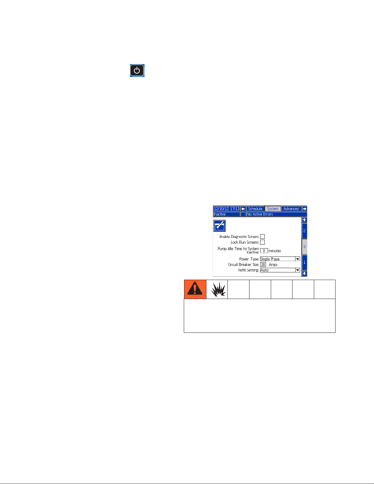
4. On the System 3 screen:
Select ADM Settings
NOTE: See Appendix A - ADM on page 104 for
detailed ADM information, including general operation.
1. Turn main power switch ON .
2. When the ADM is finished starting up, press
to switch from the Operation screens to the Setup
screens. Use , , , and to navigate
between screens.
3A2347T 21
a. Enter the main circuit breaker size used. This is
the circuit breaker installed external to the system for the system power supply.
Page 22

Setup
NOTE: If using a 480V to 240V transformer, the breaker
size entered will be two times the 480V rating. If using
transformer 24U169, the breaker size should be set to
30 amps and power type should be set to single phase.
NOTE: The InvisiPac system limits the amount of power
it pulls based on the input circuit breaker size. This
impacts the startup times because it affects the heating
energy used to warm up the materials.
b. Select the incoming power type.
5. On the Advanced 1 screen, set the system date and
time.
6. On the Advanced 2 screen, set the temperature and
mass units.
NOTE: The Schedule function enables the system to
automatically enable and disable heating at specified
times so that the system is already up to temperature
when a shift begins.
8. If desired, set any remaining settings in the Setup
screens before going on to the next steps that use
the Operation screens. These are not required for
system operation but include useful functions. See
Appendix A - ADM, beginning on page 104, for
detailed information about each setup item.
9. Press to switch from the Setup screens to the
Operation screens. Use , , , and to
navigate between screens.
10. On the Targets screen, use and , shown
next to , to adjust system melter setting.
Also, the desired temperature setting can be typed
in using the numeric keypad.
7. To setup the optional Schedule function, see
Schedule on page 29.
22 3A2347T
Page 23

11. On the Targets screen, adjust heated hose and gun
temperature settings:
NOTE: InvisiPac is a high powered tank-free system
that delivers heat faster than traditional tank systems.
Tanks are often run at a lower temperature than the
application temperature to avoid excessive adhesive
degradation since a large volume of adhesive sits at
temperature.
a. Press to select the channel.
b. Use and , shown next to , to
adjust gun temperature setting to the desired
setting for that channel.
NOTE: If a higher applicator temperature is desired,
adjust all zones to the higher temperature or adjust only
the applicator in small increments.
Setup
c. Use and , shown next to ,
to adjust heated hose temperature setting to the
desired setting for that channel.
NOTE: Alternatively, use the physical up and down
arrow push-buttons on the ADM keypad until is
next to the temperature setting to change then use the
numeric keypad to enter the desired temperature.
NOTICE
Set melter, hose, and gun to the same setpoint temperature for best performance. Do not set the hose
temperature higher than the melter. Running the hose
at a setpoint higher than the melter is unnecessary in
this tank-free system and could lead to adhesive degradation in the hose. Short adhesive residence time in
the melter eliminates the need to set the melter at a
lower setpoint than other zones. See Operation Tips
to Minimize Charring, page 33.
NOTE: Alternatively, use the physical up and down
arrow push-buttons on the ADM keypad until is
next to the temperature setting to change then use the
numeric keypad to enter the desired temperature.
Guns
Gun heating is controlled by the system, but the system
does not control opening and closing the valves. Setup
a separate gun controller to open and close the valves.
3A2347T 23
Page 24

Setup
PLC Connection
A PLC can control and monitor all items shown in the
dropdown menus on the System 1 screen in the Setup
screens.
Customer Input Dropdown Options
Option Description
Disable Not used.
Heater On/Off Turn on or off the heating system and
pump.
Channel 1, 2, 3,
or 4 Enable/Disable
Customer Output Dropdown Options
Option Description
Disable Not used.
System Ready Indicates when the system is up to tem-
Error (Alarm) Indicates when there is an active alarm.
Error (Deviation/Advisory)
Maintenance Due Indicates when the maintenance total
Enable or disable hose and gun heating for that individual channel.
perature and the pump is stalled at
pressure.
An active alarm will disable the heating
system and pump.
Indicates when there is an active deviation or advisory. An active deviation or
advisory will NOT disable the heating
system and pump.
has reached the preset notification
value.
NOTE: The InvisiPac system ships with two
screw-terminal connectors that plug into MZLP
connectors H1 and H2. Connectors are located in a bag
on the inside of the electrical enclosure front access
door. To replace the connectors, order kit 24P176.
1. On the System 1 screen (in the Setup screens)
select the function of each input on MZLP connector
H1 and each output on MZLP connector H2.
2. Turn main power switch OFF.
3. Remove electrical enclosure front access door.
4. Route I/O cable through strain relief in electrical
enclosure. See Customer I/O Cable (S) in F
IG
. 1 on
page 8.
5. Remove power from PLC.
6. Connect the PLC to connectors H1 and H2.
NOTE: Each connector has four signals. The MZLP
board specifies the input range for each signal. See the
following table for pin assignments.
J1
J2
F1
F2
F3
F4
F5
F6
F7
F8
F9
F10
J7
J6
J5
J3
H1
H2
FIG. 16: MZLP Board
H1 - Customer Input H2 - Customer Output
Signal Pin Signal Pin
1 1, 2 1 1, 2
2 3, 4 2 3, 4
3 5, 6 3 5, 6
4 7, 8 4 7, 8
NOTE: All outputs are normally open when power is
OFF. For Error (Alarm) output, the contacts open when
an alarm occurs. For all others, contacts close.
Inputs: High: 10-30 Vdc, Low: 0-5 Vdc. Inputs function
without concern for polarity. Applying “high” voltage will
turn the heaters on and enable channels. Removing
voltage will turn the heaters off and disable channels.
Outputs: 0-250 Vac, 0-30 Vdc, 2A.
24 3A2347T
Page 25

Setup
PLC Connection Block Diagrams
The following block diagrams show how to connect customer inputs and outputs to the InvisiPac MZLP. For convenience, each InvisiPac ships with connector kit 24P176. If a connector is lost or damaged, order kit 24P176 for
replacements.
FIG. 17: Customer Input
MZLP Customer In
MZLP Customer Out
Customer Output
Vin (no polarity)
30 VDC Max
Customer In
FIG. 18: Customer Output
250 VAC, 2A Max
To Customer Input
3A2347T 25
Page 26

Operation
Operation
Heating and dispensing hot melt adhesive may
create potentially harmful vapors. Read material
manufacturer’s warnings and material MSDS to know
specific hazards and precautions. Ventilation of the
work area may be required.
NOTE: See Appendix A - ADM on page 104 for
detailed ADM information.
NOTICE
To prevent damage to soft key buttons, do not press
the buttons with sharp objects such as pens, plastic
cards, or fingernails.
NOTE: Only 1/4 in. (6 mm) round hot melt adhesive pellets can be used in the InvisiPac system. PSA-type
adhesive pellets will not work in the InvisiPac system.
1. Direct the guns into an appropriate waste container.
2. Verify the shaker inlet is at the bottom of the empty
adhesive pellets container. Optional vibrating adhesive pellets container, part 24R136, is available.
See Accessories on page 89.
NOTE: The shaker inlet must be completely covered in
adhesive pellets to effectively pull pellets into the tube.
3. Fill adhesive pellets container with hot melt adhesive pellets.
NOTE: See Appendix B - USB Downloading, Uploading on page 110 for detailed USB information.
Overview
The system includes a vacuum transfer system that
pulls the adhesive pellets into the system as needed.
Once melted, the adhesive enters the pump where it is
pumped into the heated hoses then to the heated guns.
The gun then briefly opens to dispense the desired
quantity of adhesive.
Even though the system rises to operating temperature
quickly, there is a Schedule function in the ADM that
eliminates waiting for the system to heat up. The Schedule function automatically enables the heating system at
the user-specified times so the system is ready to dispense when a shift begins. The Schedule function also
disables the heating system at user-specified times to
ensure the heating system is disabled when not being
used.
4. Turn main power switch ON .
5. Open system air inlet ball valve.
WLE
6. Use pump air pressure regulator (C) to adjust pump
air pressure to 0. See F
7. Use vacuum transfer air pressure regulator (E) to
adjust vacuum transfer air pressure setting to
40-100 psi (280-690 kPa, 2.8-6.9 bar). Recommended setting is 60 psi (414 kPa, 4.1 bar). See
IG
. 1 on page 8.
Initial Startup and Prime
NOTE: All setup procedures must be completed prior to
initial startup. See Setup on page 14.
26 3A2347T
Page 27

Operation
FIG. 1 on page 8.
NOTE: Vacuum transfer will not begin operating until
pump reaches operating temperature.
To prevent fire and explosion, never exceed the
cleaning fluid’s rated temperature. If the system was
just flushed, residual cleaning fluid is still in the
system until the system is primed with adhesive. Do
not raise temperature above cleaning fluid rated
temperature until system is primed with adhesive.
NOTE: A new system may have residual oil due to testing at the factory prior to shipping. To prevent smoking,
make sure to perform the following step.
8. On new systems only: temporarily adjust the melter
temperature to 250°F (121°C). See Select ADM
Settings on page 21 for instructions.
9. Press to enable the heaters and pump.
12. With the guns open and the system up to temperature, slowly increase pump air pressure until the
pump begins to run very slowly. Approximately 20
psi (140 kPa, 1.4 bar) should be sufficient.
NOTE: Operation may be erratic below 20 psi (140 kPa,
1.4 bar).
13. Continue running the pump until clean, air-free
material is dispensed from each gun.
14. When each gun is fully primed, adjust pump to
desired pressure setting:
a. Adjust pump pressure to between 20-100 psi
(140-690 kPa, 1.4-6.9 bar).
b. Use separate gun controller to repeatedly open
and close each gun while inspecting the dispense pattern.
c. Repeat until desired dispense pattern is
achieved.
NOTE: When system is up to temperature, the pump will
be activated automatically but will not start because
there is no air pressure supplied to the pump.
NOTE: When the melter is up to temperature, the
auto-fill function will initiate to fill the funnel with pellets.
10. On new systems only: After the melter has reached
250°F (121°C) and the funnel is filled with pellets,
set the melter temperature back to the desired operating temperature. See Select ADM Settings on
page 21 for instructions.
11. Use separate gun controller to open the guns and
keep them open.
NOTICE
In the following step, to prevent damage to the pump
due to pump cavitation, do not supply more than 20 psi
(140 kPa, 1.4 bar) air pressure to the pump until the
system is fully primed.
Manual Refill
NOTE: Use Automatic Refill whenever possible. The
system uses Automatic Refill by default and must be
manually changed to Manual Refill. Only use Manual
Refill if the Automatic Refill system is not functioning
properly and cannot be fixed in a timely manner. Perform service to automatic feed system as soon as possible to limit debris buildup on feed cap.
It is recommended to maintain a minimum flow rate of
1.5 lb/hour to prevent material from melting within the
feed cap and funnel. If production rate is below
1.5 lb/hour or system sits at temperature without dispensing for extended periods of time, use manual refilling with caution. System flow rate can be monitored by
enabling the Diagnostic screen.
1. On the System 3 screen (in the Setup screens),
select “Manual” from the Refill mode dropdown.
2. Remove the phillips head screws then remove the
funnel cap from the funnel.
3A2347T 27
Page 28

Operation
3. Fill the funnel with adhesive pellets.
ti21154a
FIG. 19
4. Refill the funnel as needed to maintain the required
dispense rate.
5. When finished dispensing for the day, dispense into
a waste container until the material level is down to
the smallest diameter section of the funnel then continue purging material through the valve for an additional 75 pump strokes.
NOTE: This will lower the adhesive level within the feed
cap to the correct level to prevent any issues upon
startup the following production day.
Automatic Refill
The system uses automatic refill by default. If the automatic refill system is malfunctioning and cannot immediately be fixed, Manual Refill can be used.
To use automatic refill:
1. On the System 3 screen (in the Setup screens),
select “Automatic” from the Refill mode dropdown.
2. Verify shaker and tube are connected to the system.
See Attach Components on page 14.
3. Verify shaker inlet (K) is at the bottom of the adhesive pellets container that is filled with hot melt
adhesive pellets. See F
NOTE: The shaker inlet must be completely covered in
adhesive pellets in order for it to effectively pull pellets
into the tube.
4. If not already set, use vacuum transfer air pressure
regulator (E) to adjust vacuum transfer air pressure
setting to 40-100 psi (280-690 kPa, 2.8-6.9 bar).
Recommended setting is 60 psi (414 kPa, 4.1 bar).
See F
IG
. 1 on page 8.
NOTE: The system will automatically transfer the pellets
to the system as necessary.
IG
. 1 on page 8.
NOTE: Pump strokes can be monitored on the Maintenance screen, or by counting pump changeovers. To
count pump changeovers, listen to the air motor exhaust
pulses; two exhaust pulses equals one pump cycle (two
strokes).
ti21154a
FIG. 20
Dispense
NOTE: Only hot melt adhesive pellets can be used in
the InvisiPac system.
1. If the system is empty or has air in the lines, perform
Initial Startup and Prime procedure on page 26.
2. If main power switch is OFF, turn main power switch
ON .
NOTE: The main power switch should be left ON at all
times when using the Schedule function.
3. Prepare for dispensing:
a. Verify air inlet ball valve (J) is open. See F
on page 8.
IG
. 1
28 3A2347T
Page 29

Operation
b. Check pressure gauges (D, F) to verify vacuum
transfer and pump air pressures are set as
desired. See F
c. If using Automatic Refill, see Automatic Refill
on page 28.
d. If using Manual Refill, see Manual Refill on
page 27.
e. Verify guns are closed.
4. Press to enable the heaters and pump.
NOTE: If using the Schedule function, the heaters and
pump will be enabled automatically at the set time. You
will not need to press if using the Schedule func-
tion unless you wish to enable the heating system
before the set time.
NOTE: When system is up to temperature, the pump will
begin running automatically. It will stall at pressure
unless a gun is open. Material will be dispensed whenever a gun is open after the system is up to temperature.
5. When the system is up to temperature, use sepa-
rate gun controller to open and close the guns as
desired to dispense material.
IG
. 1 on page 8.
Shutdown
Press to disable the heaters and pump. The
screen will say “Inactive”. If using the Schedule function,
the heaters and pump will be disabled automatically at
the set time. You will not need to press if using the
Schedule function unless you wish to disable the heating system before the set time. If the heaters were manually disabled, the Schedule function will automatically
enable them at the next set time.
Do not turn the main power switch OFF if using the
Schedule function.
Schedule
The Schedule function allows the user to specify times
when the system will automatically turn ON and OFF the
heaters and pump.
NOTE: While operating the system, the actual temperatures of the hose, gun, and system melter are displayed
on the Home screen.
Set Schedule Times
NOTE: Times are set using a 24-hour clock. Several on
and off times can be set each day.
1. On the Schedule screen (in the Setup screens), set
the ON times for each day of the week.
2. Set the OFF times for each day of the week.
3A2347T 29
Page 30

Operation
Enable Schedule Function
The Schedule function is automatically enabled when
values are entered in the Schedule screen. To disable
the Schedule function, delete all values on the Schedule
screen or turn the main power switch OFF to prevent
system from automatically enabling and disabling the
heaters.
How to Use the Schedule Function
At the end of the work day leave main power switch ON
. The Schedule function will automatically enable
and disable the heaters and pump at the specified
times.
Pressure Relief Procedure
Follow the Pressure Relief Procedure whenever
you see this symbol.
Drain the System
NOTE: The system must be drained prior to flushing
and prior to some maintenance and repair procedures.
1. On the System 3 screen (in the Setup screens),
change the Refill Setting to “Manual”.
2. If the heating system is disabled, press to
enable the heaters and pump.
This equipment stays pressurized until pressure is
manually relieved. To help prevent serious injury
from pressurized fluid, such as skin injection,
splashing fluid and moving parts, follow the Pressure
Relief Procedure when you stop spraying and before
cleaning, checking, or servicing the equipment.
1. Turn main power switch OFF .
2. Close the inlet air supply ball valve.
NOTE: Manually verify the pressure is relieved by opening the gun and ensuring no adhesive is dispensed.
3. Decrease pump air pressure to 0.
4. Close system air inlet ball valve.
5. Disconnect hose from gun inlet then place hose outlet in a waste container. Repeat for all hoses. Keep
hose to gun electrical connector connected.
6. Open gun to allow residual fluid in gun to drain.
7. When system is at operating temperature, slowly
increase pump air pressure until fluid begins flowing
into the waste container.
NOTE: It may take several minutes to empty the system. When there is no melter fluid at the pump, the
pump will begin to cycle faster.
8. When the pump begins to cycle faster, close the
system air inlet ball valve.
9. Press to disable the heaters and pump.
10. Remove melter drain plug (W1). See F
9.
IG
. 2 on page
11. Disconnect hose from melter outlet.
30 3A2347T
Page 31

Operation
12. Wait until system stops draining or at most 10 minutes.
NOTE: There will be some residual adhesive in the system.
13. When done performing the procedure that required
draining the system, set Refill Setting back to “Auto”
on the System 3 screen.
Flush
To prevent fire and explosion, use the adhesive manufacturer’s recommended cleaning fluid.
• Never exceed the cleaning fluid’s rated
temperature.
• Never flush your system or clean any aluminum
components with halogenated hydrocarbon
cleaning solutions.
To prevent severe burns, wear protective clothing.
NOTE: This procedure describes how to flush one hose
at a time for maximum effectiveness.
See the hot melt adhesive technical data sheet or
MSDS for the recommended cleaning fluid. Contact the
hot melt supplier if the technical data sheet or MSDS is
not available.
1. Perform Drain the System on page 30.
5. On the System 3 screen (in the Setup screens), verify the Refill Setting is set to “Manual”.
To prevent fire and explosion, never exceed the
cleaning fluid’s rated temperature.
6. Change the melter, heated hoses, and guns temperature settings to the high temperature hot melt
cleaning fluid manufacturer’s recommended temperature.
7. Verify the system air inlet ball valve is closed and
pump air pressure is set to 0.
8. Allow the system to heat or cool to the cleaning fluid
manufacturer’s recommended temperature.
9. Fill melter with high temperature rated hot melt
cleaning fluid. See hot melt adhesive material supplier for recommended hot melt cleaning fluids.
Fluid level should be 1/2 in. (12.7 mm) from the top
of the melter.
2. If the heating system is enabled, press to dis-
able the heaters and pump.
3. Loosen hose clamp securing funnel assembly to air
motor bracket then remove funnel assembly from
system. Keep 1.3 in. (33 mm) clear tube and funnel
cap attached to funnel.
4. Loosen clamp then remove plastic melter cap. Keep
fill sensor attached to cap.
ti21053a
10. Disconnect one hose from its gun manifold.
NOTE: Keep all guns closed throughout this procedure.
3A2347T 31
Page 32
Operation
11. Route the disconnected hose to a waste container.
12. If heating system is disabled, press to enable
the heaters and pump.
13. Wait for the melter temperature to reach the hot
melt cleaning fluid manufacturer’s recommended
temperature.
NOTE: The pump will not run because the system air
inlet ball valve is closed.
14. Once the required melter temperature is reached,
let the hot melt cleaning fluid “soak” in the melter at
temperature for the duration specified by the hot
melt cleaning fluid manufacturer.
NOTE: “Soaking” is important to ensure the best possible cleaning.
15. After the hot melt cleaning fluid has “soaked” for the
specified amount of time, open the system air inlet
ball valve. Slowly increase the pump air pressure
until pump begins to cycle to begin pumping the hot
melt cleaning fluid and adhesive mixture out through
the hose into the waste container.
20. Remove and replace filter(s) in all gun manifolds.
See gun manual.
21. Replace Outlet Filter. See page 34.
22. Turn main power switch OFF.
23. Place waste container below drain tray (W2) then
remove drain plug (W1) and wait for system to finish
draining. See F
IG
. 2 on page 9.
24. Allow the system and fluid to cool then perform any
required maintenance procedures beginning on
page 34.
25. Install fill cap onto melter rubber housing.
26. Slide funnel assembly through air motor bracket
then tighten clamp.
27. On the System 3 screen (in the Setup screens), set
the Refill Setting to “Auto”.
16. Once the pump begins to cycle faster, close the system air inlet ball valve to stop the pump.
17. Repeat steps 7 through 16 until clean, adhesive-free hot melt cleaning fluid is dispensed from
the detached hose.
NOTE: Now the melter and the disconnected hose are
thoroughly flushed.
18. Reattach the hose to the gun manifold.
19. Repeat steps 7 through 18 for each additional
installed hose, leaving a different hose disconnected from the gun manifold each time.
To prevent fire and explosion, never exceed the
cleaning fluid’s rated temperature. Residual cleaning
fluid is still in the system until the system is primed
with adhesive.
28. Perform Initial Startup and Prime on page 26.
32 3A2347T
Page 33

Operation Tips to Minimize
Charring
Set the Pump Idle Time to System Inactive function
on the System 3 screen to lowest value that will not
interfere with normal operation. This feature automatically disables the heating system if the pump is idle for
longer than the preset amount of time. Disabling the
heating system minimizes adhesive degradation and
limits char formation.
When possible, utilize the Schedule function, see
page 29, to automatically enable and disable the heating system in accordance with your production schedule. This will ensure adhesive spends as little time at
temperature as possible. Less time at high temperature
ultimately means less adhesive degradation and less
char.
NOTICE
Operation
Set melter, hose, and gun to the same setpoint
temperature for best performance. Do not set the
hose temperature higher than the melter. Running
the hose at a setpoint higher than the melter is
unnecessary in this tank-free system and could
lead to adhesive degradation in the hose. Short
adhesive residence time in the melter eliminates
the need to set the melter at a lower setpoint than
other zones.
3A2347T 33
Page 34
Maintenance
Maintenance
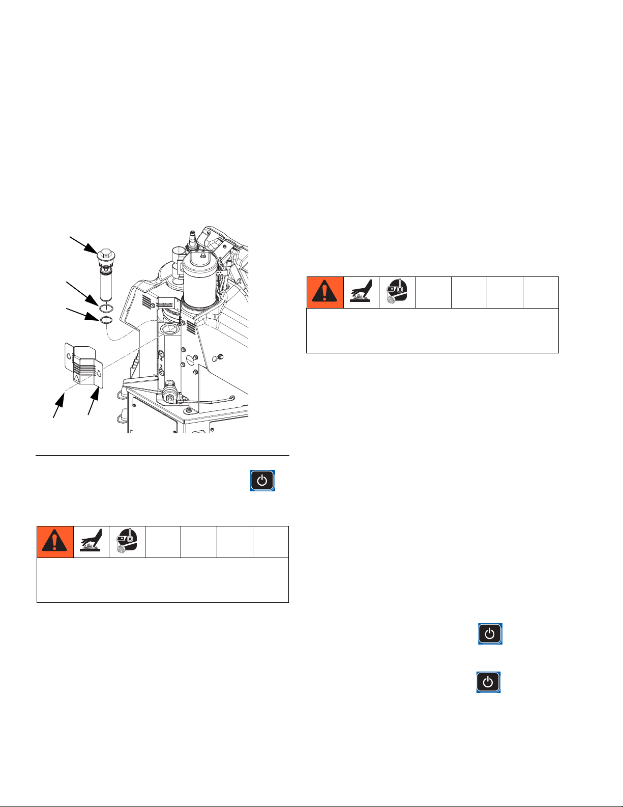
Replace Outlet Filter
The outlet filter is designed to prevent small contaminants from entering the hoses and guns. Inspect filter
regularly. Replace the filter after flushing and when you
change the adhesive used in the system.
236
232
237
6. Insert allen wrench through the outlet filter cap to lift
outlet filter (236) out of the system.
7. Discard outlet filter assembly.
8. Place o-rings (232, 237) provided with new outlet filter onto new outlet filter (236).
9. Place new outlet filter with o-rings into housing.
Tighten with 1 in. socket.
10. Install small metal shroud (28) over outlet filter then
tighten two screws (8).
Replace Inlet Filter
To avoid severe burns, wear protective gloves and
clothing that will insulate your hands and body from
the hot surfaces and material.
The inlet filter is designed to prevent large items from
entering the system. The inlet filter can only be replaced
with the system empty.
8
FIG. 21
1. If the system is not up to temperature, press to
To avoid severe burns, wear protective gloves and
clothing that will insulate your hands and body from
the hot surfaces and material.
2. Perform Pressure Relief Procedure, page 30 but
3. Turn main power switch OFF.
4. Loosen two screws (8) then slide the small metal
5. Use a 1 in. socket to unscrew outlet filter (236).
28
enable the heaters and pump then wait for system
to reach operating temperature.
do not allow system to cool. Adhesive must be a
fluid to perform this procedure.
shroud (28) on the back of the system up to remove.
See F
IG
. 21.
ti20752a
1. Close the system air inlet ball valve.
NOTE: Some adhesives have different melting points.
The first temperature tried should be approximately half
of the dispensing temperature. If dispensing at 400°F
(204°C), first try 200°F (93°C) then increase in 20°F
(11°C) increments. If dispensing at 250°F (121°C), first
try 125°F (52°C) then increase in 20°F (11°C) increments.
NOTE: To ensure the adhesive is a gel, not a liquid, do
not remove inlet filter cap (215) when the temperature is
above the desired temperature. If the temperature is too
low, the adhesive viscosity may be too high to remove
the inlet filter (213).
2. If the melter is below the desired temperature and
heating system is disabled, press to enable
the heaters.
If the melter is above the desired temperature and
heating system is enabled, press to disable
the heaters.
3. Wait until melter temperature is the desired temperature.
34 3A2347T
Page 35
Maintenance
4. When the melter temperature is the desired temperature, turn main power switch OFF.
5. Disconnect cable from ADM, push cable through
plastic shroud, then remove plastic shroud from system.
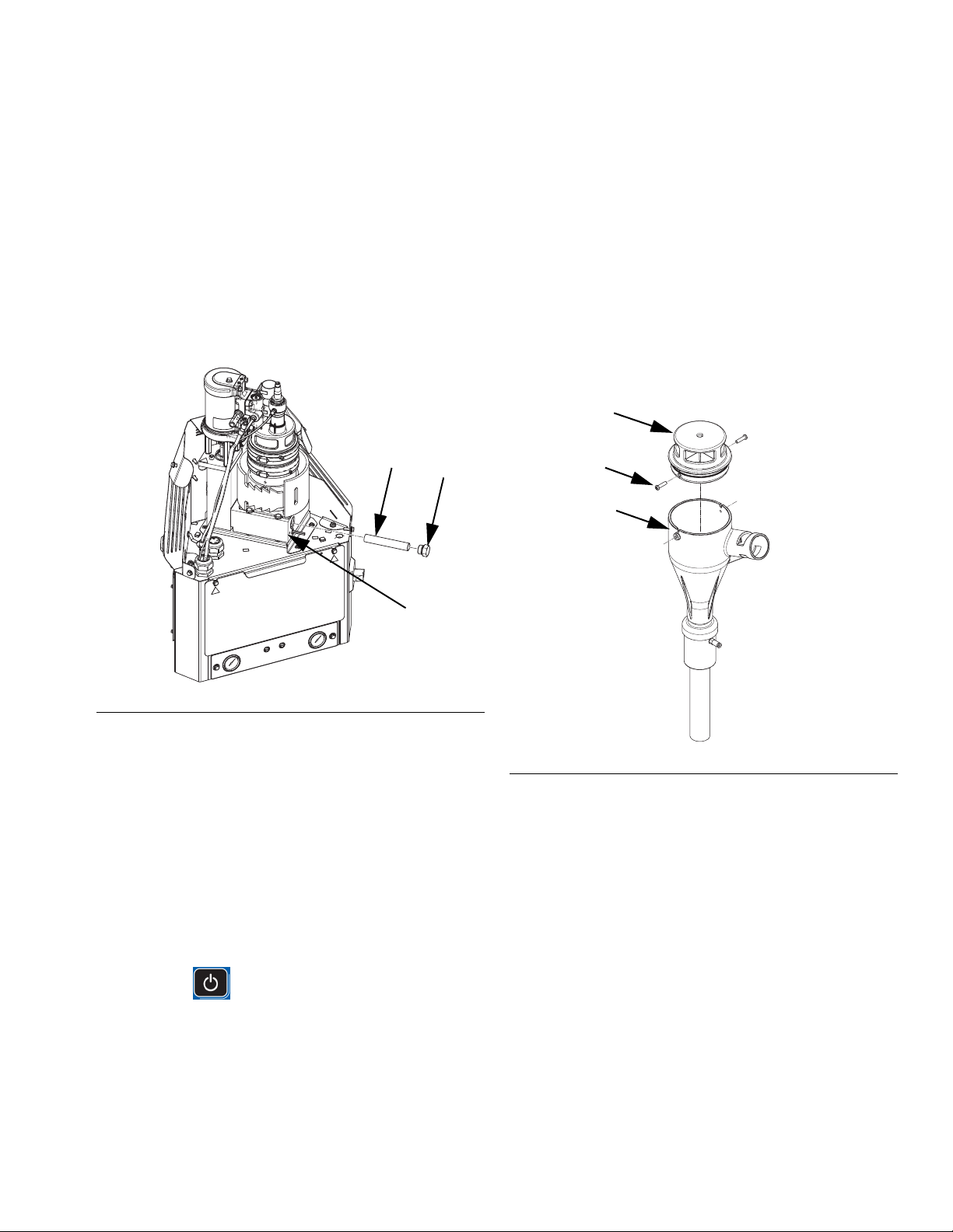
6. Place a piece of cardboard beneath the inlet filter
cap (215) to route fluid away from system into a
waste container in the event the adhesive is a fluid.
7. Use 1 in. socket to remove inlet filter cap (215).
213
215
f. Go to step 4.
9. Slide new screen (213) into melter base
manifold (201).
10. Install filter cap (215) then use a 1 in. socket to
tighten.
11. Feed ADM cable through plastic shroud (29) then
install shroud onto system. Connect cable to
ADM (30).
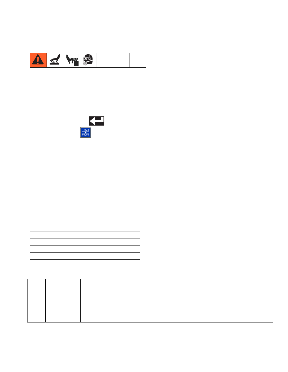
Replace Funnel Filter
701
705
706
201
ti20909a
FIG. 22
8. If the adhesive is a thin enough gel to remove the
inlet filter: Use an o-ring pick or small allen wrench
to remove filter screen (213) from system.
Otherwise:
a. Install inlet filter cap (215).
b. Install shroud and ADM.
c. Turn main power switch ON.
d. Once ADM software finishes starting up,
press to enable the heaters.
e. Wait for temperature to rise 20°F (11°C) beyond
previous temperature.
ti20927b
FIG. 23
Disassembly (see FIG. 23):
1. Turn main power switch OFF.
2. Loosen and remove the two phillips head
screws (705) on the side of the funnel (706) then
remove the funnel cap (701).
Reassembly (see F
IG
. 23):
1. Place funnel cap (701) onto funnel (706).
2. Install two phillips head screws (705) to secure funnel cap to funnel base.
3A2347T 35
Page 36

Maintenance
Filter Maintenance Guidelines*
Environment Classification
Clean Moderate Dusty
Pump inlet filter
Pump outlet filter
Gun manifold filter
System air filter
Solenoid exhaust filters
Feed funnel filter
Feed funnel inspection/clean out
* These recommendations are service level guidelines - actual service levels required in your factory will vary based
on environmental and operating conditions. High or low volume adhesive usage, as well as adhesives that contain a
powered release agent or are otherwise dusty, will have an impact on the frequency of filter maintenance. To
establish a preventative maintenance cycle tailored to your environment, Graco recommends inspecting filters every
4 weeks after installation and replacing when necessary. Document replacement intervals and use this as your
preventative maintenance schedule moving forward.
Replace
filter every
six
months
Replace
filter every
four
months
Replace
filter every
two
months
36 3A2347T
Page 37
Troubleshooting
Troubleshooting
To avoid injury due to unexpected machine operation
initiated by a remote controller, disconnect the
customer I/O cable from the system prior to
troubleshooting.
ADM Error Code Table
When an error occurs, press to acknowledge the error. If a Maintenance error occurs, navigate to the Mainte-
nance screen and press to clear the error.
The last digit of the error code indicates the melter, gun, or hose to which the error applies. The “_” (underscore)
character indicates the code applies to multiple items.
Last Digit in Code Code Relates to:
0Melter
1Gun 1
2 Hose 1
3Gun 2
4 Hose 2
5Gun 3
6 Hose 3
7Gun 4
8 Hose 4
9Gun 5
A Hose 5
BGun 6
C Hose 6
An alarm will disable the heating system and pump. A deviation or advisory with not disable the heating system and
pump.
Code Description Type Cause Solution
A4D0 High Current
Melter
A4D_ High Current
Hose X
A4D_ High Current
Gun X
Alarm Defective or shorted to ground on
the band heater or rod heater.
Alarm Defective or shorted to ground on
the hose power wires.
Alarm Defective or shorted to ground on
the heater rods in gun manifold.
Measure resistance to ground between
heater leads. Should be a high reading.
Replace heated hose.
Replace gun manifold.
3A2347T 37
Page 38

Troubleshooting
Code Description Type Cause Solution
A7D0 Unexpected
Current
Alarm Unexpected current flow to melter. Replace MZLP.
Faulty melter heater(s). Check heater resistance and resistance to ground. Replace
faulty heater(s).
A7D_ Unexpected
Current, Gun X
Alarm Unexpected current flow to gun X. Faulty MZLP. Replace MZLP.
Faulty gun heater element. Check heater
resistance and resistance to ground.
A7D_ Unexpected
Current, Hose
X
A8D0 No Current
Melter
Alarm Unexpected current flow to hose X. Faulty MZLP. Replace MZLP.
Faulty hose heat element. Check heater
resistance and resistance to ground.
Alarm Power not getting to melter. Check fuses F1 and F2 on MZLP with daugh-
ter board.
Check J1 is plugged into MZLP with daughter
board.
A8D_ No Current
Hose X
Alarm Power not getting to hose. Check fuses F5 and F6 or F9 and F10 on
MZLP that the error hose is connected to.
Check that electrical connector on the heated
hose is plugged into the MZLP.
Check continuity of pins C and D on electrical
connector at MZLP end of heated hose. See
heated hose manual for impedance measurements. Replace hose if readings are too high.
If system only uses one hose and gun, the
heated hose electrical connector must be
plugged into channel 1 of the MZLP.
A8D_ No Current
Gun X
Alarm Power not getting to gun. Check fuses F3 and F4 or F7 and F8 on
MZLP that controls the error channel.
Check that electrical plug on hose is plugged
into back of MZLP.
Check continuity of hose pin A gun end to J
on MZLP connector end of hose and pin C on
gun end to pin A on the MZLP end of the
hose. Reading should be 0-1 ohm. Replace
hose if measurement is outside this range.
If system only uses one hose and gun, electrical connector of the heated hose must be
plugged into channel 1 of the MZLP.
CAC_ Comm Error
Module
Alarm System not responding to ADM. System is not properly loaded with correct
software. Perform Software Update Proce-
dure on page 71.
Dial not set correct on MZLP. Set to 1 on
board with daughter board. Set to 2 on MZLP
without the daughter board.
CACX Missing DB Alarm System not acknowledging the
daughter board.
Defective MZLP daughter board. Replace.
Bad connection between daughter board and
MZLP board. Loosen daughter board,
re-seat, then secure.
38 3A2347T
Page 39

Code Description Type Cause Solution
DADX Pump Run-
away
Alarm Pump is trying to feed adhesive, no
adhesive to feed.
Storage bin out of adhesive. Refill adhesive.
Melter at incorrect temperature, to low. Check
setpoint and set to manufactures recommendation.
Plugged vacuum transfer hose or funnel.
Clear plugged hose or funnel.
Worn or damaged pump seals Inspect pump seals. Repair if necessary.
DDDX Pump Diving Devia-
tion
Pump is trying to feed adhesive, no
adhesive to feed.
Storage bin out of adhesive pellets. Refill with
pellets.
Melter at incorrect temperature, too low.
Check melter temperature setting and set to
manufacturer’s recommendation.
Plugged vacuum transfer hose or funnel.
Clear plugged hose or funnel.
Feed rate for dispensing too high.
Worn or damaged pump seals Inspect pump seals. Repair if necessary.
DE0X Cycle Switch
Error
Alarm No signal from air motor sensor. Check wiring on J16 of the daughter board.
See Electrical Schematics on page 72.
Defective cycle switch. Replace.
Loose cycle switch bolt. Tighten cycle switch
bolt.
L6FX Level Sensor
Error
Alarm No signal from the level sensor. Check that sensor cable is plugged into sen-
sor.
Check connector at J14 of the daughter
board.
Verify there is nothing blocking fill (level) sen-
sor line of sight.
Defective fill (level) sensor. Replace.
No air to fill cap. Check for air coming from 5/32 in. air line.
Plugged orifice in fill cap below fill
sensor.
L8FX Refill timeout Alarm Melter did not receive enough
adhesive pellets for flow rate.
Remove fill cap and remove object plugging
the orifice.
Storage bin out of adhesive. Refill adhesive.
Plugged inlet feed hose or funnel. Clear
plugged hose or funnel.
MMUX USB Log Full Advi-
sory
T1D0 Low Temp
Alarm Melter reached setpoint but
Melter
USB logs full. Data loss will occur if
not downloaded.
dropped below setpoint and can
Download USB data. See Appendix B - USB
Downloading, Uploading on page 110.
Check resistance of heater rods and band
heater.
not recover.
T1D_ Low Temp
Hose
Alarm Hose reached setpoint but dropped
below setpoint and can not
Check resistance of heated hose. Refer to
hose manual for proper resistance range.
recover.
T1D_ Low Temp
Gun
Alarm Gun reached setpoint but dropped
below setpoint and can not
Check resistance of manifold heater rods.
Refer to gun manual for resistance value.
recover.
T4C_ High MZLP
PCB Temp
Alarm MZLP board is overheating. Ambient temperature must be under 120°F.
Defective MZLP board. Replace.
Troubleshooting
3A2347T 39
Page 40

Troubleshooting
Code Description Type Cause Solution
T4D0 High Temp
Melter
T4D_ High Temp
Hose
T4D_ High Temp
Gun
T6D0 Sensor Error
Melter
Alarm Melter continues to raise above the
Defective RTD. Replace.
setpoint.
Alarm Hose continues to raise above the
Defective RTD. Replace.
setpoint.
Alarm Gun assembly continues to raise
Defective RTD. Replace.
above the setpoint.
Alarm No reading from RTD. Verify connector J5 on MZLP board is
securely connected.
Defective RTD. Replace.
T6D_ Sensor Error
Hose
Alarm No reading from RTD. Hose electrical connector not plugged into
MZLP.
Defective RTD. Replace.
T6D_ Sensor Error
Gun
Alarm No reading from RTD. Hose electrical connector not plugged into
MZLP or manifold electrical connector not
plugged into heated hose.
Defective RTD. Replace.
T8D_ No Temp Rise
in Gun (all
zones)
Alarm Temperature reading does not
change.
Check fuses F3 and F4 or F7 and F8 on
MZLP that error channel is connected to.
Defective heater rods in gun manifold.
Replace gun manifold.
T8D_ No Temp Rise
in Hose (all
zones)
T8D0 No Temp Rise
in Melter (all
zones)
Alarm Temperature reading does not
change.
Alarm Temperature reading does not
change.
NOTE: Defective heaters rods in the gun
manifold can also cause the no current error.
Heated hose electrical connector or wires are
defective. Check resistance of hose wiring.
See hose manual for proper resistance
range.
Check fuses F5 and F6 or F9 and F10 on the
MZLP that controls the error channel.
Defective heater wires in hose. Replace
heated hose.
NOTE: Defective heaters wires in the hose
can also cause the no current error.
Heated hose electrical connector or wires are
defective. Check resistance of hose wiring.
See hose manual for proper resistance
range.
Check fuses F1 and F2 on MZLP with daughter board.
Defective heater wires in melter. Replace
melter.
NOTE: Defective heaters wires in the melter
can also cause the no current error.
Check J1 is properly plugged into the MZLP
with daughter board.
Check that RTD is installed in the melter.
40 3A2347T
Page 41

Code Description Type Cause Solution
V1I_ Low Can Volt-
age
V4I_ High Can Volt-
age
V8M_ No line voltage Alarm Incoming line voltage is less than
WJDX Pump Sole-
noid Error
WKFX Fill Solenoid
Error
WSUX USB Invalid
Configuration
Alarm Bad or overloaded power supply. Verify power supply voltage is 24 VDC. If volt-
age is low, disconnect the power lines and
re-check voltage reading. If voltage is still
low, replace power supply. If voltage is cor-
rect after disconnecting the power lines,
replace the MZLP.
Alarm Bad or overloaded power supply. Verify power supply voltage is 24 VDC. If volt-
age is high, replace power supply unit.
Measure incoming power with system
100 VAC.
Alarm No voltage draw from air solenoid
for air motor.
Alarm No voltage draw from air solenoid
for fill.
Deviation
A valid configuration file can't be
found for the USB.
Bad ADM. Replace ADM.
unplugged. If line voltage is less than
100 VAC, contact qualified electrician to cor-
rect the low voltage.
Check connector is properly connected to J14
of the daughter board.
Defective air manifold, replace manifold.
Check connector at J14 of the daughter
board.
Defective air solenoids. Replace. See
page 66.
System is not properly loaded with correct
software. Perform Software Update Proce-
dure on page 71. Retry USB download.
Troubleshooting
Mechanical and Electrical Troubleshooting
Problem Cause Solution
Refill Timeout
Error
The InvisiPac
system takes a
long time to
refill adhesive.
The system was unable
to refill in less than 30
seconds.
Glue level in hopper is
low.
Vacuum flow is
restricted.
Check hopper for adequate material and material blocking.
Verify the vacuum transfer system air pressure is 40-80 psi (60 psi recommended) and that air is flowing to the feed wand while attempting to
refill.
Restart system. If the error persists after attempting another refill and
unit is needed immediately for production, place system into the manual refill mode. See Manual Refill on page 27.
Check funnel filter. If plugged, see Replace Funnel Filter on page 35.
Check hopper for adequate material and material blocking.
Verify the vacuum transfer system air pressure is 40-80 psi (60 psi recommended) and that air is flowing to the feed wand while attempting to
refill.
Check funnel filter. If plugged, see Replace Funnel Filter on page 35.
3A2347T 41
Page 42

Troubleshooting
Problem Cause Solution
Vacuum transfer not working
Adhesive pellets in storage
bin not covering shaker
head.
Fill Solenoid
Error
Air to vacuum assembly missing.
Air at system air gauge
but not to air to shaker.
Air is at shaker but
there is no feed.
Shaker unit not vibrating.
Materials are blocking
in the hopper. Some
adhesive materials are
prone to blocking. High
ambient temperature
and high humidity can
increase the likelihood
of blocking.
Failure of the fill solenoid or fill solenoid wiring.
Verify the vacuum transfer system air pressure is 40-80 psi (60 psi recommended)
Check that air line is connected or not pinched.
Plugged shaker unit, remove from system and remove plug.
Verify shaker is vibrating during material loading. If not, the ball in the
shaker assembly is stuck. Remove shaker housing and separate to
clean raceway and ball inside.
Some materials may require agitation periodically to breakup bridging.
Purchase and install 30 Gallon Vibrating Hopper, 24R136. See
page 92.
Verify wiring between J13 and the refill solenoid is not damaged.
Restart system. If the error persists after attempting another refill and
unit is needed immediately for production, place system into the manual refill mode. See Manual Refill on page 27.
Level Sensor
Error
The InvisiPac
system expels
adhesive pellets dust when
refilling.
The InvisiPac
system will not
stall, pump
continues to
move even if
the guns are
all closed.
Failure of the level sensor (20) or sensor
cable 16T108 (J14 to
level sensor (20)).
Check sensor cable J14 to level sensor (20).
Enable Diagnostic screen on ADM then check sensor readings on the
Diagnostic screen. Sensor readings should be about 3V if melter is
completely empty (melter passage holes are visible). The normal operating range is 2.1 to 2.8V. If the sensor is reading more than 2.75V the
system should be requesting additional material.
Restart system. If the error persists after attempting another refill and
unit is needed immediately for production, place system into the manual refill mode. See Manual Refill on page 27.
Some adhesives are
very dusty due to the
anti-blocking agents
used or because the
adhesive manufacturing process has created small adhesive
Replace Funnel Filter, see page 35.
NOTE: Feed cap filter maintenance should be performed at regular
service intervals. It is recommended that the feed cap filter be serviced
at a minimum of every 1200 lb dispensed, however with some adhesives the frequency may need to be increased significantly to maintain
desired system cleanliness.
shavings. Feed inlet
cap filter may have
become clogged.
Fluid leak. Verify that no external leakage is present.
Inspect and test the pressure relief valve.
Perform Flush Pressure Relief Valve, page 49.
If system is still unable to stall, the pump or pressure relief valve may
need to be repaired.
42 3A2347T
Page 43

Problem Cause Solution
Troubleshooting
The system
will not dispense material.
System is not up to
temperature.
Incorrect temperature
set points entered into
ADM.
Air motor is not receiving compressed air or
air pressure too low.
Feed pump not feeding adhesive.
Control for manifold
and guns not working.
Cycle Switch
Error
Cycle switch or cycle
switch wiring failure.
Loose or missing fastener (26).
USB Log Full The InvisiPac system
will display this notification when the USB data
logs reach 90% full.
Verify that the system is active.
Verify the temperature settings are correct.
Verify that the pump air pressure is set above 20 psi. Check the Pump
Air Solenoid Operation, page 49.
Repair or replace air control assembly as necessary.
Repair or replace pump assembly as necessary.
InvisiPac system does not control the timing of the manifold and
valves. This is a separate control that needs to be adjusted. Consult
control manufacturer or qualified electrician.
Check the wiring between the air motor cycle switch and J16.
Repair/replace as required.
Ensure fastener (26) is tight. See InvisiPac Systems section beginning on page 76 for part identification.
To prevent data loss download system data. See Appendix B - USB
Downloading, Uploading on page 110.
The InvisiPac
system is displaying pump
runaway or
pump diving.
This error generally
occurs when the pump
cavitates due to
improper material loading.
Level sensor blocked,
reading level incorrect.
The system is not supplying enough air to the
ultrasonic sensor venturi.
This can occur if the melt rate for the system is exceeded, resulting in
air entrapment within the incoming adhesive material and lower than
desired material temperature.
1. Verify that the InvisiPac system is not exceeding 33 cpm by
enabling the diagnostic screen.
2. If the cycle rate is below 33 cpm and the system is still running
away increase the InvisiPac system temperature by 10°F over the
current set point, leave hoses and guns at desired set point.
3. If the pump continues to runaway or dive continue increasing temperature by 10°F, do not exceed maximum temperature for the
material being dispensed.
NOTE: Some materials are more difficult to melt than others and it may
be impossible to process them at a rate of 25 lb/hr. The InvisiPac system was tested to achieve continuous melt rates of 25lb/hr when dispensing standard EVA packaging grade adhesives in pellet form with
an InvisiPac system temperature of 375°F and hose and valve temperatures of 350°F.
Clean feed cap by fill sensor, make sure there are no adhesive pellets
blocking the sensor hole.
Make sure the air supplied to the system is at least 80 psi (550 kPa, 5.5
bar).
3A2347T 43
Page 44

Troubleshooting
Problem Cause Solution
Unable to
achieve
25lb/hr melt
rate at the
desired adhesive temperature.
The InvisiPac system
monitors temperature
within aluminum mass
of melter (202). As melt
rates exceed 20 lb/hr a
system temperature
offset may be required.
1. If the cycle rate is below 33 cpm and the system is still running away
increase the InvisiPac system temperature by 10°F over the current
set point, leave hoses and guns at desired set point.
2. If the pump continues to runaway or dive continue increasing temperature by 10°F, do not exceed maximum temperature for the
material being dispensed.
NOTE: A 50 amp breaker is required in order to maximize startup and
flow rate performance. Set the breaker size used in the Setup screens.
NOTE: Some materials are more difficult to melt than others, therefore
it may be impossible to process them at a rate of 25 lb/hr. The InvisiPac
system was tested to achieve continuous melt rates of 25lb/hr when
dispensing standard EVA packaging grade adhesives in pellet form
with an InvisiPac system temperature of 375°F and hose and valve
temperatures of 350°F.
ADM not displaying when
system turned
on
Main breaker
tripping
Main power circuit
Turn main circuit breaker on or plug in power cord.
breaker off or power
cord unplugged.
Cable on ADM
Reconnect ADM cable.
unplugged.
Connector on MZLP
ADM cable should be plugged into J6 of the MZLP board.
board not plugged in.
Bad 24VDC power supply.
Check output on power supply should measure 24VDC, if no voltage
reading replace power supply.
ADM defective. Replace ADM.
Wrong setting in ADM
breaker setup.
Internal short to ground
in system.
Too small of a circuit
Wrong breaker setting on ADM in the breaker setting in the setup
screen.
Unplug or disconnect power and measure between each leg of the
power to ground. There should be an open resistance reading.
Consult qualified electrician for proper size circuit breaker.
breaker in main power
panel.
44 3A2347T
Page 45

Problem Cause Solution
Troubleshooting
Slow start-up
time or system
takes longer
than 10 minutes to startup
No adhesive or
little adhesive
being dispensed
Wrong setting in ADM
breaker setup.
Wrong breaker setting on ADM in the breaker setting in the setup
screen.
Low incoming voltage. Incoming voltage should be 200-240VAC for a 230 volt unit and 380-
400 VAC for a 400 volt unit.
Heater rod defective.
Melter and gun mani-
Measure and check heater rods in melter or manifold. Manifold resistance 130-140 ohms.
fold.
Heated hose defective. Measure heater wires in hose, pins C and D. See repair section for
each hose resistance.
Insufficient power supplied to system.
Depending on hose
and gun combinations,
Connect system to a power supply capable of maximum power per
system specification. All changes must be performed by a qualified
electrician. See Electrical Schematics on page 72 for details about
connecting to a different power supply.
along with minimal supply power, startup time
will vary.
Incorrect RTD setting in
system.
1. Verify melter, hose, and manifold temperatures are all with in the
same range of the room ambient.
2. If the manifold temperature is either much higher or much lower than
the melter temperature then the RTD setting is not correct for the
RTD being used. Select correct RTD setting in the setup screen system 2 before beginning.
System indicates no errors
and correct
temperature
however manifold and gun
are over the
temperature
setpoint
Incorrect RTD setting in
system.
NOTE: Failure to have the correct RTD value will cause the manifold
and gun to either under-heat or over-heat. Setting for RTD in the ADM
screens is higher than actual RTD value. Consult manufacturer for
actual RTD value.
1. Verify melter, hose, and manifold temperatures are all with in the
same range of the room ambient.
2. If the manifold temperature is either much higher or much lower than
the melter temperature then the RTD setting is not correct for the
RTD being used. Select correct RTD setting in the setup screen system 2 before beginning.
NOTE: Failure to have the correct RTD value will cause the manifold
and gun to either under-heat or over-heat. Setting for RTD in the ADM
screens is lower than actual RTD value. Consult manufacturer for
actual RTD value.
3A2347T 45
Page 46

Troubleshooting
Problem Cause Solution
No adhesive or
incorrect
amount of
adhesive output when all
valves are triggered
No adhesive or
incorrect
amount of
adhesive out of
one/some of
the valves
when triggered
Plugged gun manifold
filter.
Replace manifold filter. Graco manifold filter in bottom of manifold or
inline filter on other manifolds.
Clogged hose. Flush or replace hose.
Defective solenoid
valve.
No signal from control
to solenoid.
Solenoid mufflers
Check that correct voltage is input into valve solenoid. If voltage is correct, replace solenoid.
If no voltage is present at solenoid, check control cable and remote
control device. Replace component.
Replace solenoid mufflers.
plugged.
No air to air solenoid. Re-establish air supply to solenoid.
Plugged system outlet
Replace Outlet Filter. See page 34.
filter.
If multiple valves are
triggered simultane-
Stagger valve opening to reduce the maximum required flow rate to
below maximum pump rate.
ously, maximum pump
rate may be exceeded.
Plugged tip on gun. Replace tip on gun.
Defective gun in
Replace gun.
closed/partial open
position.
Plugged manifold filter
(single valves mani-
Replace manifold filter. Graco manifold filter in bottom of manifold or
inline filter on other manifolds.
fold).
Clogged hose (single
valves).
Defective solenoid
valve (single manifold).
No signal from control
to solenoid (single
valve manifold).
Plugged solenoid mufflers (single valve manifold).
No air to solenoid (single valve manifold)
Plugged system outlet
filter.
If multiple valves are
triggered simultaneously, maximum pump
rate may be exceeded.
Flush or replace hose.
Check that correct voltage is input into valve solenoid. If voltage is cor-
rect, replace solenoid.
If no voltage is present at solenoid, check control cable and remote
control device. Replace component.
Replace solenoid mufflers.
Re-establish air supply to solenoid.
Replace Outlet Filter. See page 34.
Stagger valve opening to reduce the maximum required flow rate to
below maximum pump rate.
46 3A2347T
Page 47

Problem Cause Solution
Troubleshooting
Adhesive flowing out of
one/some
valves when
not triggered
Gun will not
heat.
Adhesive leaking from manifold or valve.
Failed valve in the
Replace valve.
open position.
Adhesive pressure too
Reduce air pressure to air motor.
high.
Heat rod failure in manifold.
Loose cable connec-
Check resistance on heater rods. Repair manifold if heater rods measure open.
Check cable connections on both ends of the hose.
tion at system or manifold.
RTD failure. Check resistance on the RTD, if out of normal range replace RTD.
Incorrect RTD setting in
the ADM setup.
Thermal cutoff is
Set correct RTD value in the AMD setup screen. Consult manufacture
for correct RTD value.
Measure resistance of the thermal cutoff. If open, replace.
tripped.
Valve is loose on the
Tighten screws on loose valve.
manifold.
Valve o-ring failed. Replace o-rings on the back of the leaking valve.
Failed valve, adhesive
Replace valve.
leaking out middle of
valve.
No melter
heat.
Air motor will
not function.
System not
turning on.
Hose loose. Tighten hose.
Fuse blown in F1 and
F2.
Cable to over-temperature switch off or bro-
Check heater rods for a short or a short between the rod wires and
ground.
Check connection of cable to over-temperature switch both to main
board and to switch. If connection good, look for break in wire.
ken.
Over-temperature
switch tripped.
Measure over-temperature switch resistance. It should read close to 0
ohms when at room temperature. If open, replace over-temperature
switch.
No air being supplied to
air motor.
Air solenoid not adjusting the air motor.
Air present at air motor
Check incoming air supply. Check that air solenoid is adjusted for air
motor.
If air can not be adjusted at the air solenoid, check voltage, if 24VDC
present at air solenoid replace air solenoid.
Replace air motor.
but it will not work.
No power to unit. Check main power breaker is turned on.
Check that power plug is connected.
3A2347T 47
Page 48

Troubleshooting
Problem Cause Solution
Static shock
when touching
shaker or
adhesive bin.
Adhesive not
dispensing at
the correct
time.
Ground wire not in
place on shaker
assembly. Some adhesives, flow rates, and
ambient conditions can
cause excessive static
buildup on the shaker
tube.
Guns opening at the
wrong time.
Attach a ground wire from the shaft of the shaker unit to a true earth
ground. Order shaker grounding kit 24R708.
InvisiPac system does not control the opening and closing of the guns.
The separate controller needs to be adjusted. Consult control manufacturer or qualified electrician.
48 3A2347T
Page 49
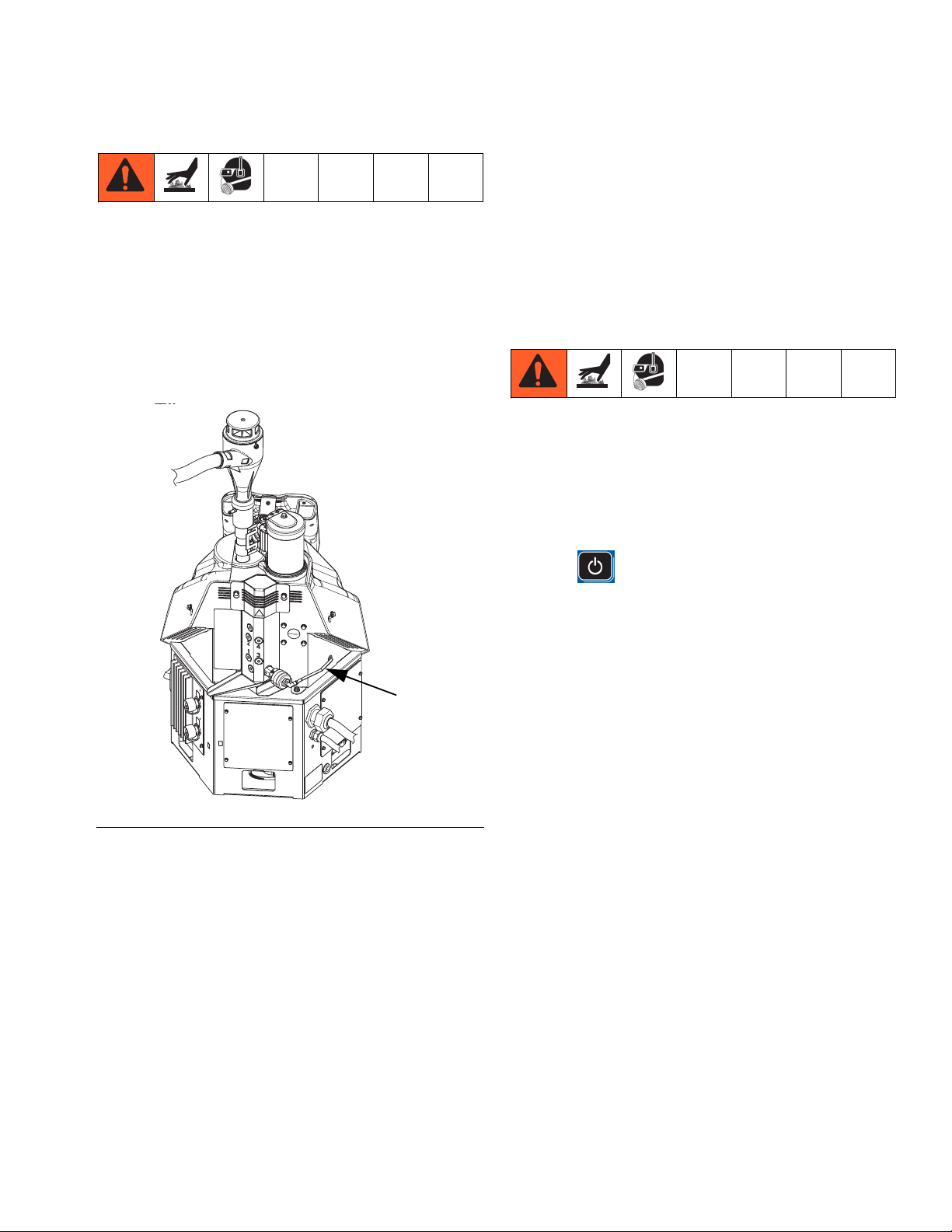
Troubleshooting
Flush Pressure Relief Valve
Perform this procedure when directed in the Troubleshooting table.
1. With the system active at the required adhesive
temperature, set the air motor air pressure to 20 psi
(140 kPa, 1.4 bar).
2. Remove the air line (36) from the pressure relief
valve.
3. Plug air line and allow the air motor to cycle.
4. Re-connect air line to relief valve and check whether
the system will stall.
5. If system still does not stall, purge ten pump cycles
of material through one gun.
6. Repeat this entire procedure until no additional air is
expelled from the gun.
Check the Pump Air Solenoid Operation
Perform this procedure when directed in the Troubleshooting table.
NOTE: System must be up to operating temperature for
pump solenoid to trigger on.
1. If the heating system and pump is disabled,
press to enable the heaters and pump.
FIG. 24
ti20441b1
36
2. Wait for system to reach the temperature setpoints.
3. Set pump air pressure to 20 psi (140 kPa, 1.4 bar).
4. Remove the 3/8 in. OD air line from the air motor.
5. Verify that air is flowing through the air line.
6. If air is not flowing, check the wiring between J13
and the pump solenoid.
3A2347T 49
Page 50
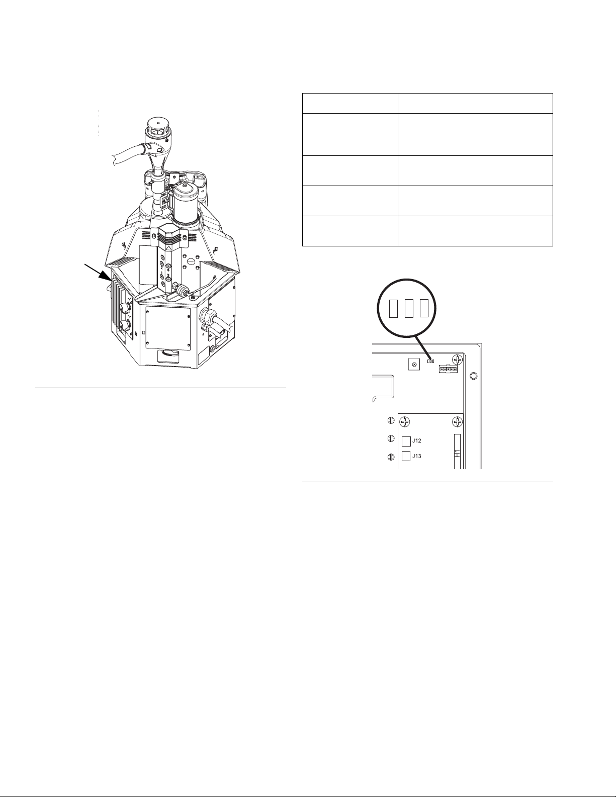
Troubleshooting
MZLP Troubleshooting
MZLP
ti20441b1
Signal Description
Green On MZLP is powered up and input
voltage is within operating conditions.
Yellow On Internal communication in pro-
cess
Red Solid MZLP failure. See troubleshoot-
ing table.
Red Flashing Software update in process or
missing software.
Yellow
1
0
9
8
7
6
5
Red
2
3
4
Green
FIG. 25: MZLP LED Signals
NOTE: The MZLP LED is located on the inside of the
electrical enclosure. To view, remove the electrical
enclosure front access door.
J3
ti20348a
FIG. 26: MZLP Diagnostic LED Location
50 3A2347T
Page 51
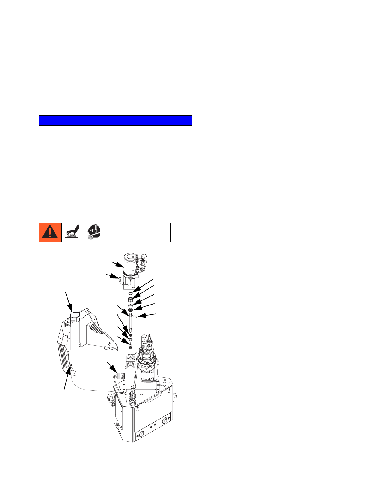
Repair
Repair
NOTE: Some procedures require special tools. Read
through each procedure prior to beginning it to ensure
you have the required tools to complete the entire procedure. Order any required tools and have them on
hand prior to beginning the procedure.
NOTICE
When performing any procedure that requires
removal of seals or other soft parts, do not leave a
system that has not been flushed disassembled for
more than 30 minutes to prevent the adhesive from
hardening. Hardened adhesive will damage the seals
and other soft parts during installation.
Pump
Replace Throat Seal, Throat Bearing, Piston Rod,
Piston Seal, and Piston Bearing
Disassembly (see F
1. Flush the system. See page 31.
2. Close the bleed-type ball valve installed at the system air inlet to relieve all air pressure in the system.
3. Turn main power switch OFF.
4. Remove plastic shroud (27).
5. Remove vacuum transfer inlet funnel.
6. Remove air lines from relief valve (245) and air
motor (218).
7. Remove four nuts (3) securing melter shield (27) in
place then remove melter shield.
8. Remove air motor assembly:
a. Remove retaining ring (239).
b. Remove dowel pin (238).
c. Remove three screws (240).
IG
. 27):
FIG. 27
27
3
240
245
218
223
225
226
222
239
235
233
234
238
ti21046a
9. Use a flat head screwdriver and a rubber mallet to
break loose the retaining nut (235).
10. Use channel lock pliers to remove the retaining
nut (235).
11. Insert an allen wrench through the hole in the top of
the piston rod (223) to lift the piston rod (223) up out
of the manifold. This will also pull out the throat
u-cup (234) and throat bearing (233).
12. Remove piston valve (222) from piston rod (223).
13. Remove and discard piston u-cup (225) and
bearing (226).
Reassembly (see F
1. Assemble piston rod:
a. Install new piston u-cup (225) onto piston
rod (223) with the lips facing the rod.
b. Install piston bearing (226) onto piston rod (223)
with grooved end towards the center of the piston rod.
IG
. 27):
3A2347T 51
Page 52
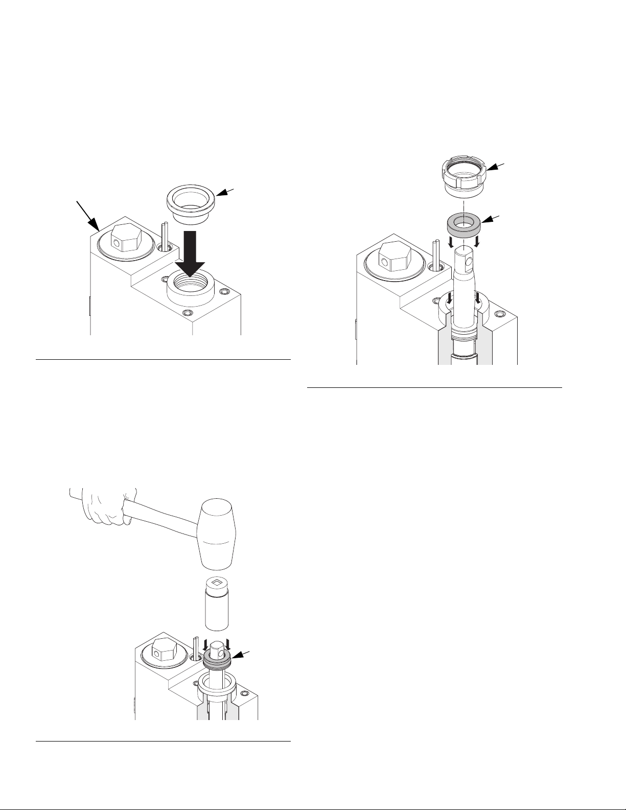
Repair
c. Install piston valve (222) onto piston rod (223).
Torque to 24-30 ft-lb (33-41 N•m).
2. To protect the seals from the sharp threads, place
seal installation tool 15B661 into the throat bore.
See F
IG
. 28.
15B661
203
ti20877a
FIG. 28
3. Push the piston rod assembly (223) into the melter
outlet manifold (203).
4. Grease the throat u-cup (234) and slide the u-cup
over the piston rod (223) with the lips facing down.
6. Slide throat bearing (233) over the piston rod (223).
Use socket and tap with a rubber mallet to press
throat bearing (233) into place and seat the throat
u-cup.
235
233
ti21144a
FIG. 30
7. Remove seal installation tool.
IG
8. Install retaining nut (235). See F
. 28.
5. Place a 7/8 in. deep-well socket (3/8 in. drive) over
the piston rod (223) then use a rubber mallet to gently tap throat u-cup (234) into place. See F
IG
. 29.
234
ti21047a
FIG. 29
9. Install air motor assembly (see F
IG
. 27):
a. Install three screws (240).
b. With retaining ring around piston rod, install
dowel pin (238).
c. Install retaining ring (239) over dowel pin.
10. Use nuts (3) to install melter shield (27).
11. Connect air lines to relief valve and air motor.
12. Install plastic shroud (27).
52 3A2347T
Page 53
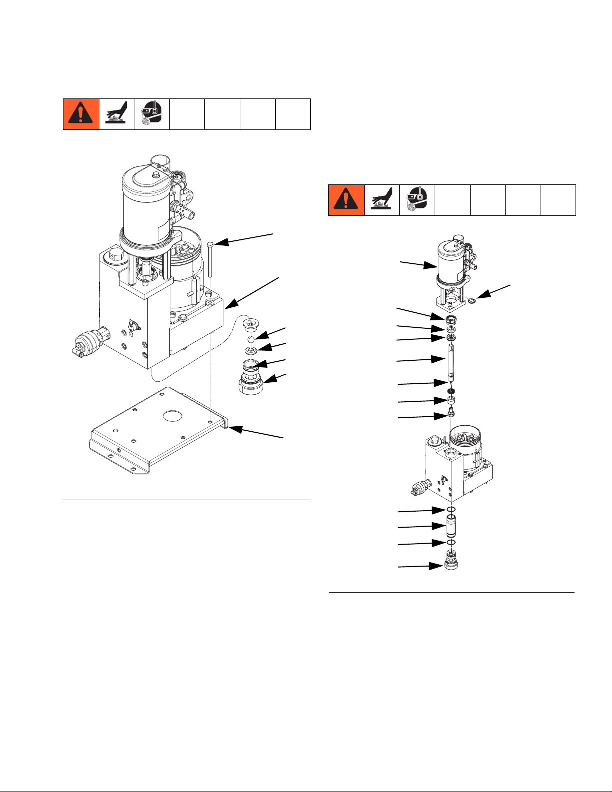
Repair
Replace Pump Inlet Housing Checks
254
201
227
228
229
230
Reassembly (see F
IG
. 31):
1. Install new o-ring (229), seat (228), and ball (227)
then use a 1/2 in. drive ratchet without a socket to
install and tighten foot valve (230) onto melter.
2. Install Melter Assembly. See page 56.
Replace Pump Cylinder Seals and Piston Seals
218
239
235
233
234
233
224
257
ti20749a
FIG. 31
Disassembly (see F
IG
. 31):
1. Flush the system. See page 31.
2. Close the bleed-type ball valve installed at the system air inlet to relieve all air pressure in the system.
3. Turn main power switch OFF.
4. Remove Melter Assembly. See page 55.
5. Use a 1/2 in. drive ratchet without a socket to
remove foot valve (230) from bottom of melter outlet
manifold (203).
6. Remove and discard seat (228), ball (227), and
o-ring (229).
226
222
217
216
217
230
ti21048a
FIG. 32
Disassembly (see F
IG
. 27):
1. Flush the system. See page 30.
2. Close the bleed-type ball valve installed at the system air inlet to relieve all air pressure in the system.
3. Turn main power switch OFF.
4. Remove plastic shroud (27). See F
IG
. 27 on
page 51.
3A2347T 53
Page 54
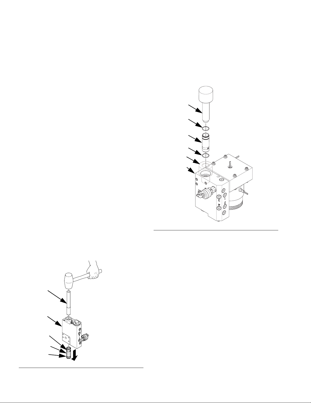
Repair
5. Remove air lines from relief valve (245) and air
motor (218) See F
IG
. 27 on page 51.
6. Remove nuts (3) securing melter shield (27) in
IG
place then remove melter shield. See F
. 27 on
page 51.
7. Remove air motor assembly. See F
IG
. 27 on
page 51:
a. Remove retaining ring (239).
b. Remove dowel pin (238).
c. Remove three screws (240).
8. Use a flat head screwdriver and a rubber mallet to
break loose the retaining nut (235).
9. Use channel lock pliers to remove the retaining
nut (235).
10. Insert an allen wrench through the hole in the top of
the piston rod (223) to lift the piston rod (223) up out
of the manifold. This will also pull out the throat
u-cup (234) and throat bearing (233).
14. Remove and discard cylinder seals (217). See F
IG
.
31.
Reassembly:
1. Apply grease to seals (217) then install new cylinder
seals (217) onto cylinder (216). See F
IG
. 31.
1303
217
216
217
1302
203
11. Remove Melter Assembly. See page 55.
12. Use a 1/2 in. drive ratchet without a socket to
remove foot valve (230) from bottom of melter outlet
manifold (203).
13. Insert cylinder tool (1301) into bottom of melter outlet manifold (203). Use a rubber mallet to gently
remove cylinder (216). See F
IG
. 31.
1301
203
217
216
217
ti20880a
FIG. 33
ti21049a
FIG. 34
2. Place female cylinder installation tool (1302) into
melter outlet manifold (203) to protect seals from
sharp threads. See F
IG
. 34.
3. Use male cylinder installation tool (1303) to press
cylinder (216) into melter outlet manifold (203). If
necessary, use rubber mallet tap into place. See
F
IG
. 31.
4. Use a 1/2 in. drive ratchet without a socket to install
and tighten foot valve (230) into bottom of melter
outlet manifold (203).
5. Perform Install Melter Assembly on page 56.
6. Perform Reassembly portion of the Replace Throat
Seal, Throat Bearing, Piston Rod, Piston Seal,
and Piston Bearing procedure which starts on
page 51.
54 3A2347T
Page 55

Repair
Melter
Remove Melter Assembly
61
62
13
12
13
53
52
30
29
27
3. Turn main power switch OFF.
4. Disconnect all heated hoses from the melter outlet
manifold (203).
5. Remove cable from ADM (30) then slide forward the
shroud (29) and remove it from the system.
6. Remove screws (8) then remove electrical enclosure front access door (10).
7. Remove the air tube (36) from the relief valve (245).
Pull the air tube from the metal shroud (27).
8. Remove nuts (3) on the back metal shroud (27)
then remove shroud.
9. Loosen hose clamp on air motor bracket (528) then
remove funnel (61).
10. Remove wire connectors from the over-temperature
switch (251).
11. Remove insulators (52, 53) from the melter
assembly (5).
12. Disconnect the fill sensor cable from the fill
sensor (20).
3
259
8
3
10
ti21050b
1
FIG. 35
NOTE: This only needs to be done when replacing
items that require access to the bottom of the melter
assembly.
1. Perform Drain the System procedure on page 30
then wait for system to cool.
2. Close the bleed type ball valve at the system air
inlet.
13. Disconnect the pump cycle sensor cable from the
air motor.
14. Remove the air tube from the fill cap (62).
15. Remove the air tube from the air motor (218).
16. Loosen screw (AA) then remove sensor (125). See
F
IG
. 36 on page 57.
17. Remove electrical enclosure front access door (10).
18. Remove all heater wires from the following terminals. Pull wires up through the rubber grommet on
the top of the electrical enclosure (1). See F
IG
. 36
on page 57 for references.
Item
Wire
Marking 1
Wire
Marking 2
Band Heater (208) TB1-11B TB1-13B
Melter Heater Rod
TB1-14C CR1-NC
(209)
Base Heater Rod (210) TB1-11C TB1-13C
Pump Heater Rod
TB1-12B CR1-COM
(250)
3A2347T 55
Page 56
Repair
19. Remove four nuts (3) then remove melter assembly
from system. Save any loose insulators for reassembly.
20. Remove bolts (259) then remove melter assembly
from melter base (257).
Install Melter Assembly
1. Route melter heater rod (209) wire through large
hole in the melter base (257) then through small
hole in side of melter base (257).
2. With the 10 insulators (4) in place on the melter
assembly, place melter assembly on melter
base (257).
NOTICE
To prevent crushing the soft insulators (4), do not
overtighten the 4 bolts (259) in the following step.
Torque to 5-11ft-lb (7-15 N•m).
3. Use 4 bolts (259) to secure melter assembly to
melter base (257).
4. Use four nuts (3) to secure melter assembly to system.
5. Group the 4 sets of heater wires together and run
them through the grommet on the top of the electrical enclosure (1). Connect wires as noted below.
See F
IG
. 36 on page 57 for references.
6. Connect air tube to air motor (218).
7. Connect air tube to fill cap (62).
8. Connect fill sensor cable to the fill sensor (20).
9. Connect pump cycle sensor cable to air motor.
10. Install funnel (61) into air motor bracket (528) then
tighten clamp.
11. Install temperature sensor (125) into melter then
tighten screw (AA) on band heater. See F
IG
. 36 on
page 57.
12. Install insulators (52, 53) onto the melter
assembly (5).
13. Connect wire connectors to the over-temperature
switch (251). See F
IG
. 38 on page 59.
14. Use nuts (3) to install metal shroud (27).
15. Pull the relief valve air tube (36) through the metal
housing then attach air tube to relief valve (245).
16. Install front access door (10) onto electrical
enclosure (1).
17. Feed ADM cable through shroud then install shroud
and connect cable to ADM.
18. Reconnect all heated hoses to the melter outlet
manifold (203).
19. Turn main power switch ON.
20. Open system air inlet ball valve.
Item
Wire
Marking 1
Wire
Marking 2
Band Heater (208) TB1-11B TB1-13B
Melter Heater Rod
TB1-14C CR1-NC
(209)
Base Heater Rod (210) TB1-11C TB1-13C
Pump Heater Rod
TB1-12B CR1-COM
(250)
56 3A2347T
Page 57
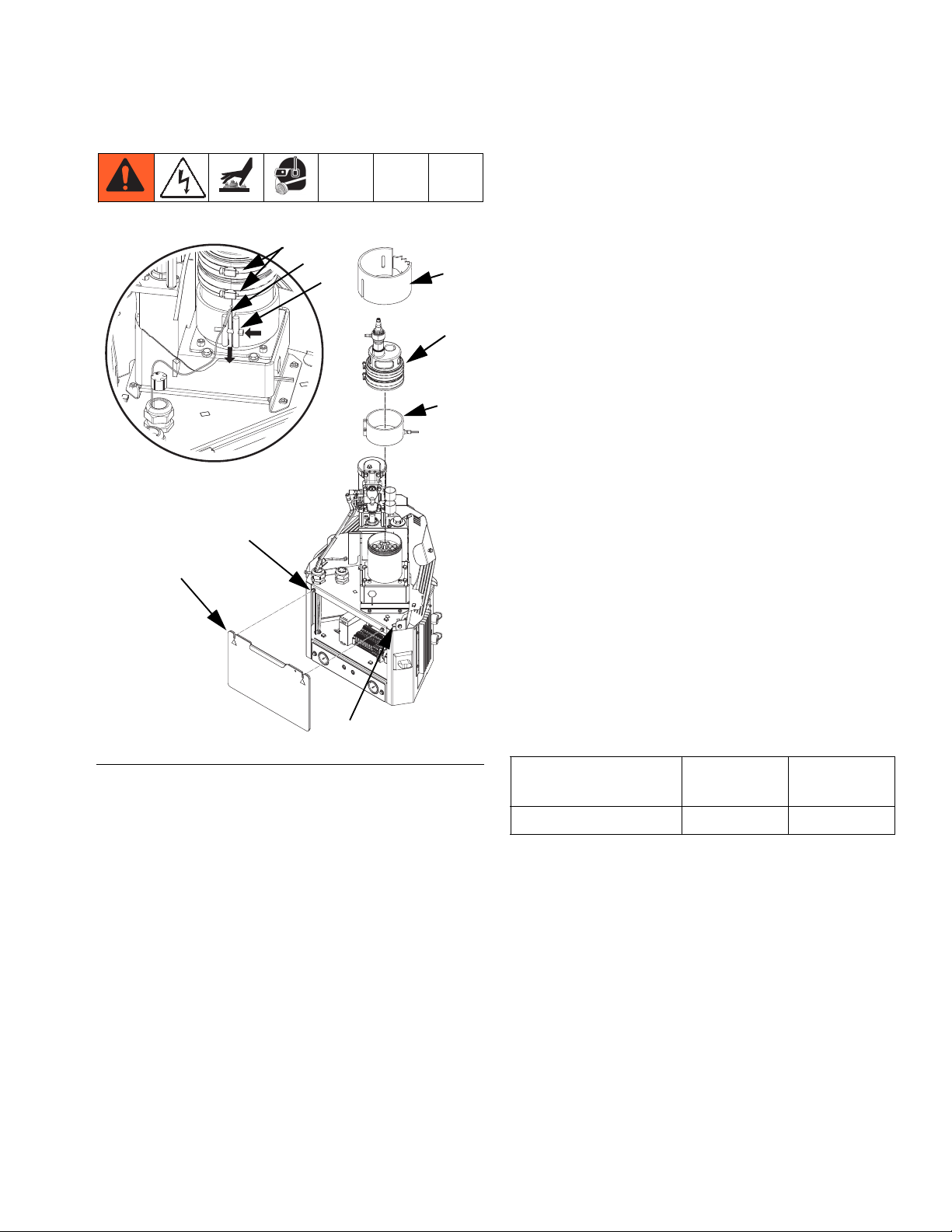
Repair
Replace Band Heater
1
10
CC
125
AA
53
62
208
8. Loosen band clamps (CC) then slide fill cap (62)
and rubber housing off melter.
9. Loosen screw (AA) then remove sensor (125).
10. Locate the wires in terminal blocks TB1-11B and
TB1-13B. Loosen terminal block screws and
remove wires.
11. Pull wires up through grommet (63) on top of the
electrical enclosure (1). Clip any wire ties that hold
the wires in place.
12. Continue loosing screw (AA) then slide band
heater (208) up to remove.
Reassembly (see F
IG
. 36):
1. Install band heater (208) on the melter with the
opening and screw facing the front of the system in
alignment with the sensor port.
2. Install sensor (125).
3. Slide band heater up then tighten screw (AA).
NOTE: Band heater should be oriented to hold sensor in
place when tightened. It should not bend the sensor.
63
ti20753a
FIG. 36
Disassembly (see F
IG
. 36):
1. Loosen clamp on air motor bracket (528) then
remove funnel assembly (61).
2. While looking through the hole in the fill cap, dispense until the fluid level in the melter is at or below
the honeycomb grid.
3. Once the fluid level is low enough, close the
bleed-type ball valve installed at the system air inlet.
4. Turn main power switch OFF.
5. Disconnect cable from ADM (30) then remove
shroud (29).
6. Remove front access door (10) from electrical
enclosure (1).
7. Remove fabric melter insulator (53).
4. Route band heater wires through grommet (63) in
the top of the electrical enclosure (1).
5. Connect wires to terminals as marked. Wires should
be marked as shown in the following table. Tighten
terminal block screws.
Item
Wire
Marking 1
Wire
Marking 2
Band Heater (208) TB1-11B TB1-13B
6. Install electrical enclosure access door (10). See
F
IG
. 36.
7. Install fabric melter insulator (53).
8. Install fill cap (62) rubber housing with band clamps
in place.
9. Install funnel into fill cap (62) then tighten band
clamps (CC) on rubber housing.
10. Slide funnel assembly (61) through air motor
bracket (528) then tighten clamp.
11. Feed ADM cable through shroud then install shroud
and connect cable to ADM.
3A2347T 57
Page 58

Repair
12. Open system air inlet ball valve.
13. Turn main power switch ON.
Replace Band Heater Temperature Sensor
53
CC
AA
40
125
ti20762a
FIG. 37
Disassembly (see F
IG
. 37):
1. Close the bleed-type ball valve installed at the system air inlet to relieve all air pressure in the system.
9. Disconnect the temperature sensor cable from
MZLP connector labeled J5. See F
IG
. 37.
NOTE: This connector also includes the over-temperature switch wires.
10. Disconnect wire connectors from over-temperature
switch (251). See F
IG
. 38 on page 59.
11. Pull cable out of the electrical enclosure then discard sensor (125) and wires.
Reassembly (see F
IG
. 37):
1. Route new harness wires through grommet (63) in
the top of the electrical enclosure.
2. Connect wire connectors to over-temperature
switch (251). See F
IG
. 38 on page 59.
3. Place band heater temperature sensor (125) in
melter.
4. Tighten screw (AA).
NOTE: Screw should lightly squeeze the temperature
sensor to hold it in place. It should not bend the sensor.
5. Connect new harness to MZLP connector labeled
J5.
6. Install electrical enclosure access door (10). See
F
IG
. 36 on page 57.
2. Turn main power switch OFF.
3. Disconnect cable from ADM then remove shroud.
4. Remove air tube (36) from relief valve. Pull the air
tube through the metal shroud (27).
5. Remove nuts (3) then remove metal shroud (27).
6. Remove fabric melter insulator (53).
7. Loosen screw (AA) then remove sensor (125).
8. Remove electrical enclosure access door (10).
7. Install fabric melter insulator (53).
8. Use nuts (3) to install metal shroud (27).
9. Route relief valve air tube through the metal shroud
then attach to the relief valve.
10. Feed ADM cable through shroud then install shroud
and connect cable to ADM.
11. Turn main power switch ON.
12. Open system air inlet ball valve.
58 3A2347T
Page 59

Repair
Replace Heater Over-Temperature Switch
251
255
ti21052a
FIG. 38
Disassembly (see F
IG
. 37):
1. Close the bleed-type ball valve installed at the system air inlet to relieve all air pressure in the system.
2. Turn main power switch OFF.
3. Disconnect cable from ADM then remove shroud.
6. Open system air inlet ball valve.
7. Turn main power switch ON.
Replace Heater Rod
206
250
210
206
ti20755a
4. Remove air tube (36) from relief valve. Pull the air
tube through the metal shroud (27).
5. Use 7/16 in. socket to remove nuts (3) then remove
metal shroud (27).
6. Disconnect the wire connectors from the over-temperature switch (251).
7. Remove the screws (255) securing the over-temperature switch (251) to the melter assembly (5),
then remove the switch.
Re-assembly (see F
IG
. 37):
1. Use the two screws (255) to secure the new
over-temperature switch (251) to the melter.
2. Connect wire connectors to new over-temperature
switch.
3. Use 7/16 in. socket to install nuts (3) to secure
metal shroud (27).
4. Route relief valve air tube (36) through the metal
shroud then attach to the relief valve.
5. Feed ADM cable through shroud then install shroud
and connect cable to ADM.
209
206
209
ti20754a
FIG. 39
Disassembly (see F
IG
. 39):
NOTE: This procedure is for replacing any of the above
heater rods.
1. Turn main power switch OFF.
2. If replacing the melter heater rod (209), Remove
Melter Assembly. See page 55.
3. Disconnect cable from ADM then remove
shroud (29).
4. If removing the pump heater rod (250):
a. Remove the air tube (36) from the relief
valve (245). Pull the air tube through the metal
shroud (27).
3A2347T 59
Page 60

Repair
b. Remove nuts (3) then remove shroud (27).
5. Remove electrical enclosure front access door (10).
See F
IG
. 36.
6. Disconnect heater rod wires from terminal blocks
described in the following table.
Item
Melter Heater Rod
Wire
Marking 1
TB1-14C CR1-NC
Wire
Marking 2
(209)
Base Heater Rod (210) TB1-11C TB1-13C
Pump Heater Rod
TB1-12B CR1-COM
(250)
7. Pull heater rod wires up through the grommet in the
top of the electrical enclosure (1).
8. Remove heater rod retaining ring (206) then remove
and discard heater rod (209, 210, or 250).
Reassembly (see F
IG
. 39):
1. Route new heater rod cable through grommet (63)
in top of electrical enclosure then connect new
heater rod wires to terminal blocks as described in
the previous table.
c. Pull the air tube through the metal shroud (27)
then connect the air tube (36) to the relief
valve (245).
7. Feed ADM cable through plastic shroud then install
plastic shroud and connect cable to ADM.
Replace Fluid Pressure Relief Valve
27
3
36
244
245
NOTICE
To prevent damaging the heater rod, do not use thermal grease in the following step.
2. Install heater rod then install heater rod retaining
ring (206). See F
IG
. 39.
3. Install electrical enclosure access door (10). See
F
IG
. 36.
4. If replacing the melter heater rod (209), Install
Melter Assembly. See page 55.
5. If replacing pump heater rod (210 or 250), feed
ADM cable through shroud then install shroud and
connect cable to ADM.
6. If installing the pump heater rod (250), install the
metal shroud (27):
a. Place metal shroud on system.
b. Install and tighten nuts (3).
ti20757a
FIG. 40
1. Drain the System. See page 30.
2. Close the system air inlet ball valve.
3. Turn main power switch OFF.
4. Remove the air tube (36) from the relief valve (245).
Pull the air tube through the metal shroud (27). See
F
IG
. 40.
5. Remove nuts (3) then remove shroud (27).
6. Use crescent wrench to remove melter fluid pressure relief valve (245).See F
IG
. 40.
7. Use an o-ring pick to remove o-ring (244).
8. Install o-ring (244) into manifold.
NOTICE
To prevent damage to o-ring, ensure o-ring is seated
properly prior to moving to next step.
60 3A2347T
Page 61

Repair
9. Thread new fluid pressure relief valve (245) into
manifold. See F
IG
. 40. Once hand-tight, use cres-
cent wrench to tighten.
10. Use nuts (3) to install metal shroud.
11. Connect air tube to pressure relief valve.
12. Feed ADM cable through plastic shroud then install
shroud and connect cable to ADM.
3A2347T 61
Page 62

Repair
Multi-Zone Low Power Temperature Control Module (MZLP)
Replace MZLP Fuse
MZLP Identification
24R234 24V510
Key
A F1 and F2 fuses are physically the same size as F3-F10 F1 and F2 fuses are physically larger than F3-F10
B --- Blue sticker on relay
C Marked 24N568 Marked 24V133
Fuse Part
C
J7
J6
F10
J5
F9
F8
F7
F6
F5
J2
F4
F3
F2
J3
F1
J1
A
B
24R234 MZLP Fuses
F1, F2 250VAC, 16A, fast acting, white
F3-F10 250VAC, 8A, fast acting
24V510 MZLP Fuses
F1, F2 250VAC, 25A, fast acting, white, 0.25 in x 1.2 in
F3-F10 250VAC, 8A, fast acting
Fuse Kits
Kit MZLP Description
WLD
FIG. 41: MZLP ID and Fuse Locations
24P859 24R234 Includes standard clear fuses.
24X479 Includes ceramic fuses used for
food industries.
NOTICE
To prevent system damage, always use fast acting
fuses. Fast acting fuses are required for short-circuit
24V289 24V510 Includes standard clear fuses.
24X480 Includes ceramic fuses used for
food industries.
protection.
1. Turn main power switch OFF.
2. Remove electrical enclosure front access door (10).
62 3A2347T
Page 63

Repair
3. Use a proper non-conductive fuse puller tool to
remove the blown fuse.
NOTICE
Using an improper tool, such as screw drivers or pliers may break glass on fuse.
4. Use a proper non-conductive fuse puller tool to
install the new fuse.
NOTICE
Using an improper tool, such as screw drivers or pliers may break glass on fuse.
5. Install electrical enclosure front access door (10).
Replace MZLP
Use See MZLP Identification, page 62.
Disassembly:
1. Turn main power switch OFF.
5. Remove four screws (114) securing MZLP (112) to
electrical enclosure (1) then carefully remove MZLP
from electrical enclosure. See F
IG
. 42.
6. If replacing MZLP #1, remove the daughter card and
standoffs, and re-install them on the new MZLP.
See F
IG
. 42 for MZLP #1 and MZLP #2 identifica-
tion.
Reassembly:
1. Set MZLP rotary switch to “1” on MZLP with daughter card. Set MZLP rotary switch to “2” on MZLP
without daughter card. See F
IG
. 43 for rotary switch
location.
2. Use four screws (114) to install MZLP (112) to electrical enclosure (1).
3. Reconnect cables to MZLP (112).
NOTE: Do not force the electrical connection. Minimal
force is required to seat the connector. If resistance is
felt, stop and verify the connector orientation.
NOTE: If unable to determine connector location, see
Electrical Schematics on page 72.
4. Install electrical enclosure front access door (10).
2. Remove electrical enclosure front access door (10).
3. Disconnect heated hose electrical connectors from
MZLP (112).
4. Note location of each cable, then unplug all cables
from the MZLP (112) that will be replaced. See F
IG
43.
ti20910a
MZLP #2
1
MZLP #1
112
114
FIG. 42
5. Connect heated hose electrical connectors to new
MZLP.
NOTE: MZLP may need updated software. See Software Update Procedure on page 71.
Replace MZLP Daughter Card
.
Disassembly:
1. Turn main power switch OFF.
2. Remove electrical enclosure front access door (10).
3. Note location of each cable then unplug all cables
from MZLP daughter card (112a). See F
IG
. 43.
3A2347T 63
Page 64
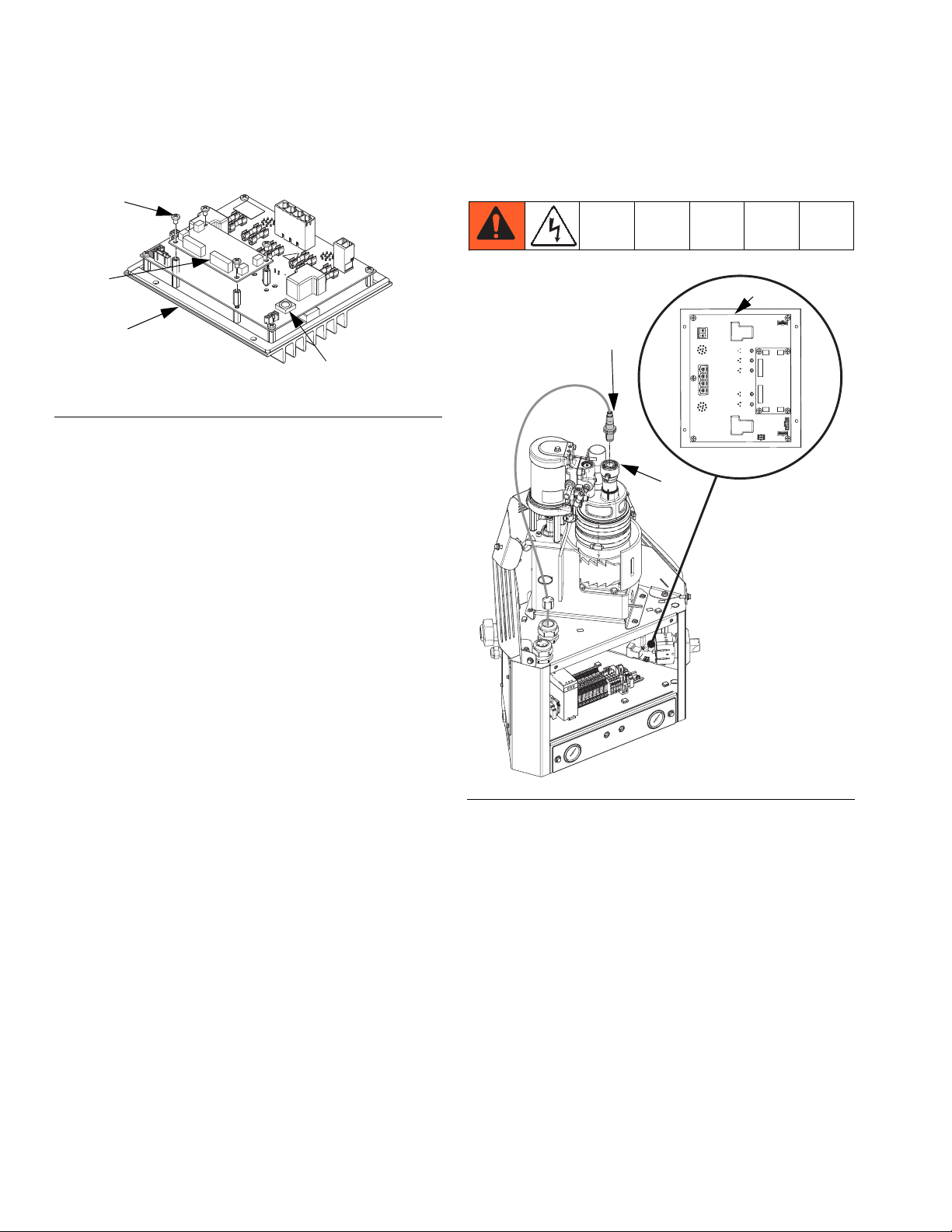
Repair
4. Remove four mounting screws (112b) from daughter card (112a) and set aside. See F
IG
. 43.
112b
112a
ti20342a
112
Rotary Switch
FIG. 43
5. Unplug daughter card (112a) from the MZLP (112).
Reassembly:
1. Plug new daughter card (112a) into the MZLP (112).
2. Use screws (112b) to secure daughter card to
MZLP (112).
System
Replace Fill Sensor
112
20
62
3. Connect cables to new daughter card (112a).
NOTE: Do not force the electrical connection. Minimal
force is required to seat the connector. If resistance is
felt, stop and verify the connector orientation.
NOTE: If unable to determine connector location, see
Electrical Schematics on page 72.
4. Install electrical enclosure front access door (10).
ti20761a
FIG. 44
Disassembly (see F
IG
. 44):
1. Turn main power switch OFF.
2. Gently pull up on cable while unscrewing fill sensor
connector then remove fill sensor cable from fill
sensor (20).
3. Loosen fill sensor jam nut then remove fill
sensor (20) from fill cap (62).
Reassembly (see F
IG
. 44):
1. Thread new fill sensor (20) into fill cap (62). Bottom
out the sensor in the fill cap then back out 1/2 turn.
2. Tighten jam nut on fill sensor (20).
3. Connect fill sensor cable to new fill sensor (20).
64 3A2347T
Page 65
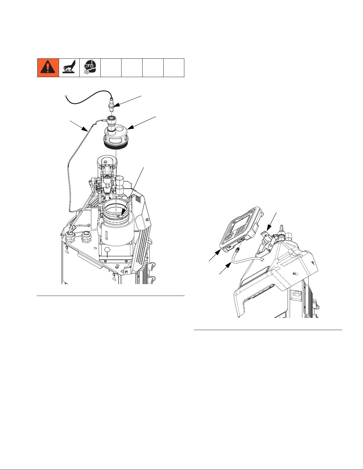
Repair
Replace Fill Cap
35
20
13
62
7. Loosen upper clamp (13) on rubber housing then
remove fill cap (62).
Reassembly (see F
IG
. 45):
1. Place new fill cap on melter. Align funnel inlet hole
with bracket.
2. Install funnel through air motor bracket (528) then
tighten funnel clamp.
3. Tighten rubber housing clamp (13) to secure fill cap
in place.
4. Connect air line (35) to fill cap (62).
5. Thread fill sensor (20) into fill cap (62). Bottom out
the sensor in the fill cap then back out 1/2 turn.
6. Tighten jam nut on fill sensor (20).
Replace ADM
58
ti20760a
FIG. 45
Disassembly (see F
IG
. 45):
1. Turn main power switch OFF.
2. Close the bleed-type ball valve installed at the system air inlet to relieve all air pressure in the system.
3. Disconnect cable from ADM then remove shroud.
4. Loosen hose clamp on air motor bracket (528) then
remove funnel assembly.
5. Loosen fill sensor jam nut then remove sensor (20)
from fill cap (62).
6. Remove air line (35) from fill cap (62).
30
CC
ti20763a
FIG. 46
1. Turn main power switch OFF.
2. Disconnect cable (CC) from bottom of ADM (30).
See F
IG
. 46.
3. Remove ADM from bracket (58).
4. Install new ADM into bracket.
5. Connect cable to bottom of new ADM.
NOTE: ADM may need updated software. See Software Update Procedure on page 71.
3A2347T 65
Page 66

Repair
Air Controls
Replace Air Control Solenoids
402
FF
FIG. 47
405
Reassembly (see F
IG
. 47):
1. Use two screws (405) to secure new
solenoids (402) to air control assembly (409).
2. Feed the new solenoid cable into the electrical
8
enclosure and attach cable to MZLP daughter board
connector J13.
9
3. Insert hands through access holes (FF), see F
IG
.
47, in bottom of electrical enclosure then connect air
lines to air control solenoids (402).
4. Slide air control assembly (9) into place then use
two screws (8) to secure to electrical enclosure (1).
5. Install electrical enclosure front access door.
Replace Air Control Gauge
1
ti20764a
8
403
403b
403a
403c
9
NOTE: In order to replace the air control solenoids, the
system must be tipped back to access underneath the
electrical enclosure.
Disassembly (see F
IG
. 47):
1. Turn main power switch OFF.
2. Close the bleed-type ball valve installed at the system air inlet to relieve all air pressure in the system.
3. Remove front access panel (10) from electrical
enclosure (1).
4. Use 3/8 in. socket to remove two screws (8).
5. Note location of each air line connection.
6. Insert hands through access holes (FF), see F
IG
.
47, in bottom of electrical enclosure then disconnect
air lines from air control solenoids (402).
7. Disconnect air control solenoids cable from MZLP
daughter board connector J13. Pull wire out of the
electrical enclosure.
8. Remove two screws (405) securing solenoids (402)
to air control assembly (9) then remove air control
solenoids.
402
ti20765a
FIG. 48
Disassembly (see F
IG
. 48):
1. Turn main power switch OFF.
2. Close the bleed-type ball valve installed at the system air inlet to relieve all air pressure in the system.
3. Remove two screws (8) then slide air control
assembly (9) out from electrical enclosure (1) so the
back of the gauges are exposed.
4. Remove two nuts (403a) securing gauge (403) in
place then remove bracket (403c).
5. Place one small crescent wrench on the brass part
of the gauge then use a second small crescent
wrench to remove the air fitting (403b).
66 3A2347T
Page 67
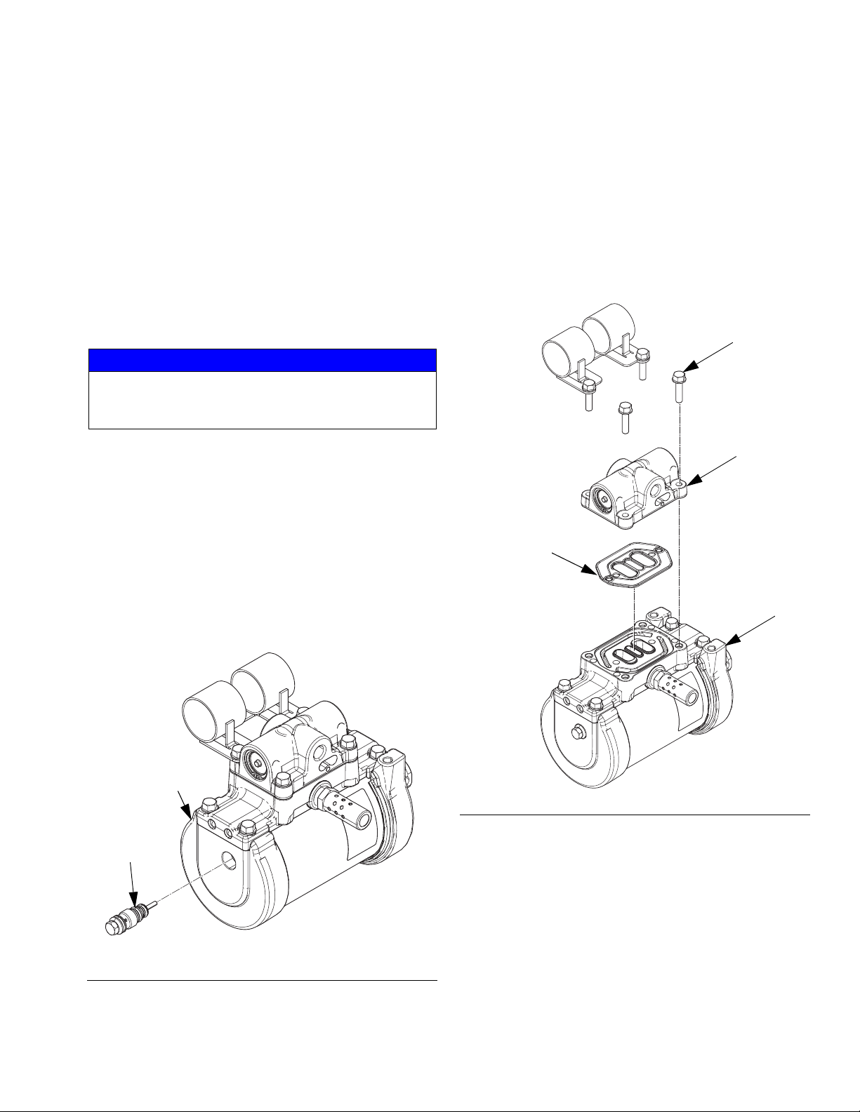
Repair
6. Remove air gauge from panel.
Reassembly (see F
IG
. 48):
1. Slide new air gauge into panel and slide the bracket
onto the back of the gauge. Install air fitting onto the
gauge by hand, do not tighten yet.
2. Install bracket (403c) then install two nuts (403a)
finger tight.
3. Place one small crescent wrench on the brass part
of the gauge then use a second small crescent
wrench to tighten the air fitting (403b).
NOTICE
In the following step, do not overtighten the two
nuts (403a). Overtightening may cause the gauge to
break.
4. Orient gauge as desired then tighten two
nuts (403a) to secure gauge (403) in place.
5. Slide air control assembly (9) into place then use
two screws (8) secure to electrical enclosure.
2. Turn main power switch OFF.
3. Use 10 mm socket to remove air motor pilot
valve (513) from air motor (218).
4. Lubricate with grease and install new air motor pilot
valve (513).
5. Torque pilot valve to 95-105 in-lb (10.7-11.9 N•m).
Replace Air Valve
508
527
509
Air Motor
Replace Pilot Valve
218
513
ti20767a
FIG. 49
1. Close the bleed-type ball valve installed at the system air inlet to relieve all air pressure in the system.
218
ti20768a
FIG. 50
Disassembly (see F
IG
. 50):
1. Close the bleed-type ball valve installed at the system air inlet to relieve all air pressure in the system.
2. Turn main power switch OFF.
3. Loosen clamp on air motor bracket (528) then
remove funnel assembly (61).
4. Loosen upper hose clamp on rubber housing then
remove fill cap.
3A2347T 67
Page 68
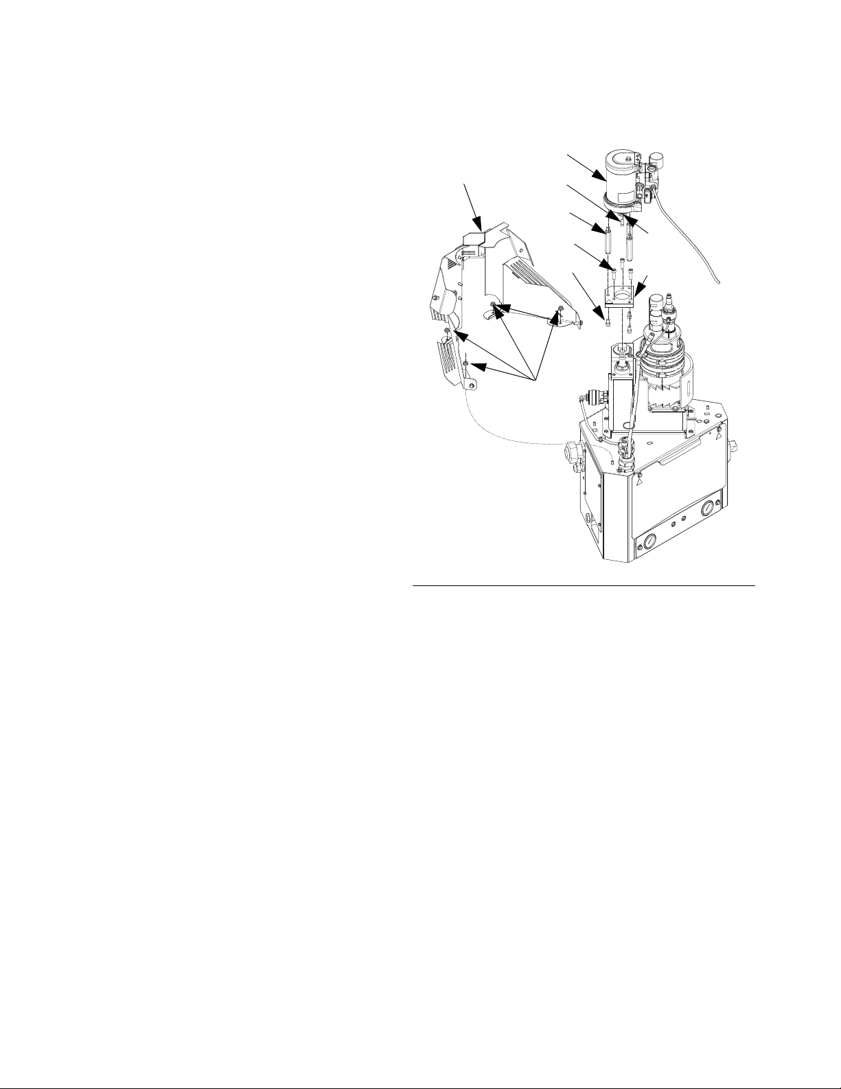
Repair
5. Dispense until the fluid level in the melter is at or
below the honeycomb grid.
NOTE: If a screw or air valve seal is dropped during this
procedure it could fall into the melter. Melter fluid level
must be below honeycomb grid before moving to next
step.
6. Once the fluid level is low enough, close the
bleed-type ball valve installed at the system air inlet.
7. Disconnect air hose and cable from the air motor.
8. Use 10 mm socket to remove four screws (508)
securing air valve (527) to air motor (218).
9. Remove air valve (527) and seal (509) then discard.
Reassembly (see F
IG
. 50):
1. Lubricate with grease then place new air valve
seal (509) onto air valve (527).
2. Carefully place new air valve (527) against air motor
then thread in the four screws (508). Ensure the air
valve seal (509) stays in place by applying constant
pressure against the air motor.
Remove Air Motor
27
218
238
3
220
240
211
239
219
3. Use 10 mm socket to torque screws (508) to
95-105 in-lb (10.7-11.9 N•m).
4. Install fill cap then tighten upper hose clamp on rubber housing.
5. Connect air hose and cable to the air motor.
ti20758a
FIG. 51
See F
IG
. 51.
1. Close the bleed-type ball valve installed at the system air inlet to relieve all air pressure in the system.
2. Turn main power switch OFF.
3. Disconnect air line (36) from pressure relief
valve (245) then pull through metal shroud (27). See
F
IG
. 40 on page 60.
4. Remove three nuts (3) securing metal shroud (27)
in place then remove metal shroud (27).
5. Disconnect air supply line from air motor (218).
6. Remove air motor assembly:
a. Slide retaining ring (239) down.
b. Remove dowel pin (238).
c. Remove three screws (240).
68 3A2347T
Page 69
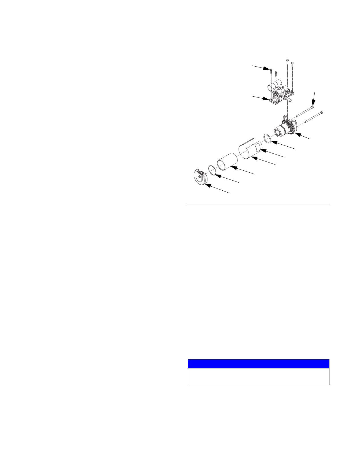
Repair
7. If replacing a damaged air motor with a new fully
assembled air motor:
a. Remove three screws (211) securing air motor
tie rods (220) to base plate (219).
b. Remove tie rods (220) from air motor (218).
Install Air Motor
IG
See F
. 51.
1. If replacing a damaged air motor with a new fully
assembled air motor:
a. Install tie rods (220) onto air motor (218).
b. Install three screws (211) securing air motor tie
rods (220) to base plate (219).
2. Connect air motor assembly to system:
a. Install three screws (240) to secure air motor
assembly to system.
b. Install dowel pin (238).
c. Install retaining ring (239) over dowel pin (238).
3. Use four nuts (3) to install melter shield (27).
4. Reconnect air supply line to air motor (218).
5. Reconnect air line (36) to pressure relief
IG
valve (245). See F
. 40 on page 60.
Replace Air Motor Piston O-Ring
511
512
520
501
504
523
506
505
505
ti20766a
510
FIG. 52
Disassembly (see F
IG
. 52):
1. Close the bleed-type ball valve installed at the system air inlet to relieve all air pressure in the system.
2. Turn main power switch OFF.
3. Remove Air Motor, page 68.
4. Use 10 mm socket to remove four screws (511) to
remove air manifold assembly (520). See F
IG
. 52.
5. Use 13 mm socket to remove two bolts (512) then
remove air motor top cap (510).
6. Remove and discard piston o-ring (504) from
piston (519).
Reassembly (see F
IG
. 52):
1. Lubricate all seals with grease.
2. Install new piston o-ring (504) onto piston (519).
NOTICE
Carefully reassemble air motor to prevent damage to
seals.
3. Reassemble remaining air motor parts, excluding air
manifold assembly, then install two bolts (512) finger tight.
3A2347T 69
Page 70
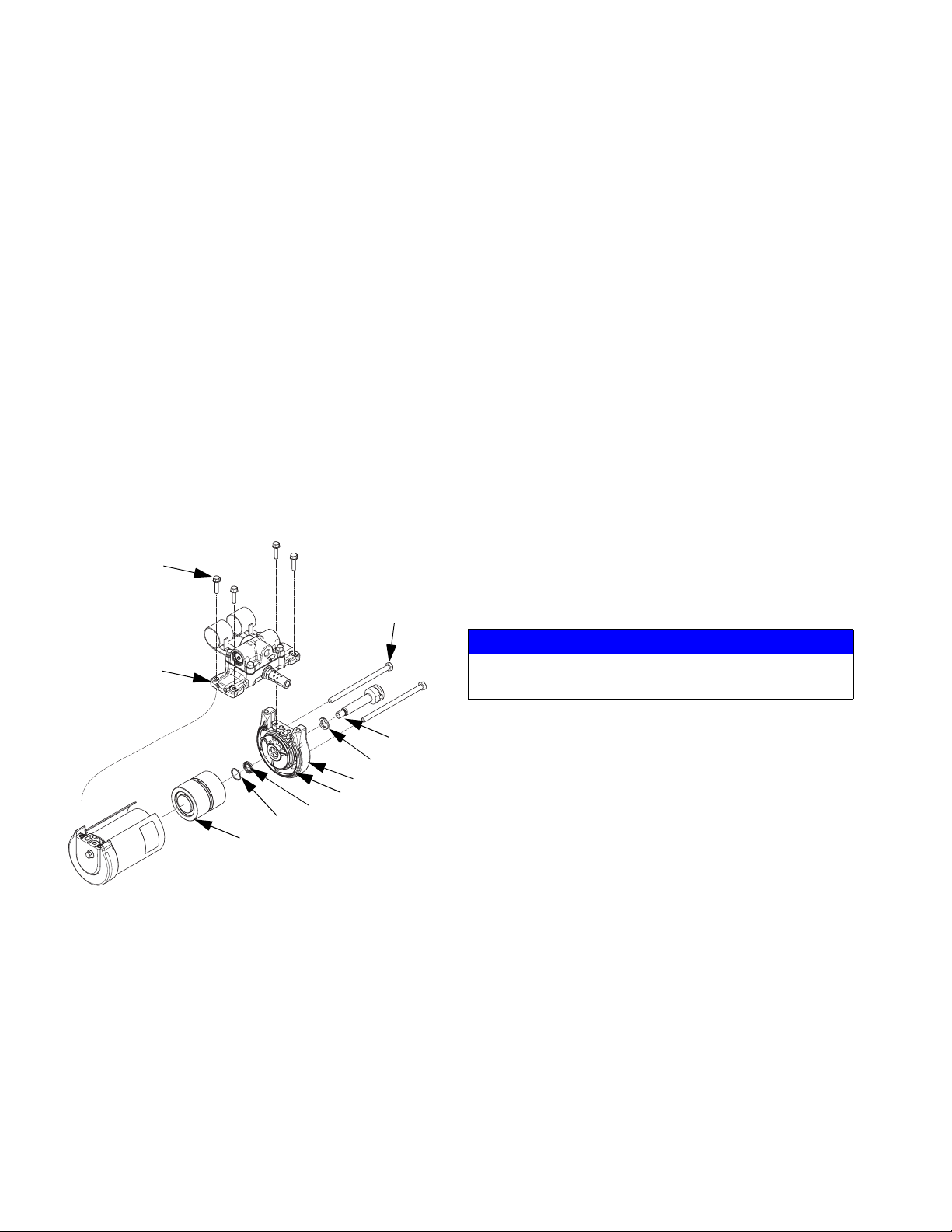
Repair
4. Use four screws (511) to install air manifold
assembly (520) onto air motor finger tight to align
cover (506).
5. Torque two bolts (512) incrementally to 11-13 ft-lb
(15-18 N•m) to ensure top and bottom cap
seals (505) seat properly.
6. Torque four air manifold screws (511) to
95-105 in-lb (10.7-11.9 N•m).
7. Install Air Motor, page 69.
Replace Air Motor Throat Seals
NOTE: This procedure uses adhesive that requires a
12-hour system idle time for full cure. If possible, perform this procedure at the end of the day or week so it
can cure overnight or over the weekend while the system does not need to run. Otherwise, keep a spare air
motor on hand so it can be used while the adhesive
cures.
511
512
4. Remove four screws (511) to remove air manifold
assembly (520).
5. Remove two bolts (512) then carefully remove air
motor base cap (501) from the rest of the air motor
assembly.
6. Disconnect rod (223) from air motor piston (519)
then remove rod from air motor base cap (501).
7. Remove retaining ring (517) from base cap (501)
8. Remove two u-cup throat seals (507) from throat of
air motor base cap (501) and discard seals.
Reassembly (see F
IG
. 53):
1. Apply water-resistant grease to new u-cup
seals (507) then install seals into throat of air motor
base cap (501).
2. Install retaining ring (517) in base cap (501).
3. Carefully insert rod (223) into air motor base cap.
4. Apply high strength adhesive, supplied with kit, to
rod threads then connect rod (223) to air motor
piston (519). Torque to 35-40 ft-lb (47-54 N•m).
520
223
507
501
502
507
517
519
ti20769a
FIG. 53
Disassembly (see F
IG
. 53):
1. Close the bleed-type ball valve installed at the system air inlet to relieve all air pressure in the system.
2. Turn main power switch OFF.
3. Remove Air Motor, page 68.
NOTICE
Carefully reassemble air motor to prevent damage to
seals.
5. Reassemble remaining air motor parts, excluding air
manifold assembly, then install two bolts (512) finger tight.
6. Use four screws (511) to install air manifold
assembly (520) onto air motor finger tight to align
cover (506).
7. Torque two bolts (512) incrementally to 11-13 ft-lb
(15-18 N•m) to ensure top and bottom cap
seals (505) seat properly.
8. Torque four air manifold screws (511) to
95-105 in-lb (10.7-11.9 N•m).
9. Install Air Motor, page 69.
10. Prior to using system, wait 12 hours for adhesive
used in step 4 to fully cure.
70 3A2347T
Page 71
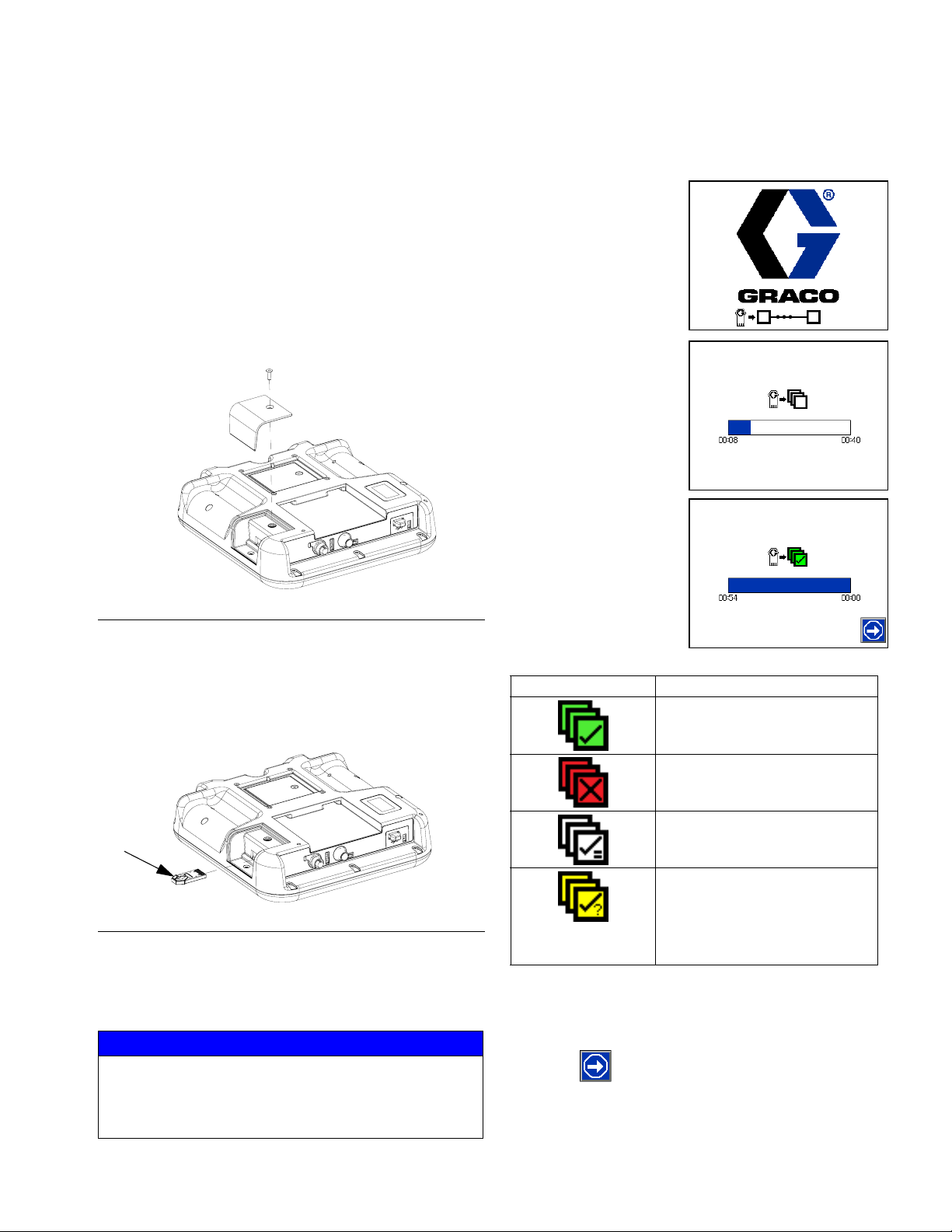
Repair
Software Update Procedure
When software is updated on the ADM the software is
then automatically updated on all connected GCA components. A status screen is shown while software is
updating to indicate progress.
1. Turn system main power switch OFF.
2. Remove ADM from bracket.
3. Remove token access panel.
r_24P860_3B9900_3a
F
IG
. 54: Remove Access Panel
NOTE: When the screen turns on, you will see the fol-
lowing screens:
First:
Software is checking
which GCA modules
will take the available
updates.
Second:
Status of the update
with approximate time
until completion.
Third:
Updates are complete.
Icon indicates update
success/failure. See
the following Icon
table.
4. Insert and press InvisiPac software upgrade token
(T, part no. 24R324) firmly into slot.
NOTE: There is no preferred orientation of token.
T
r_24P860_3B9900_4a
IG
. 55: Insert Token
F
5. Install ADM into bracket.
6. Turn system main power switch ON.
NOTICE
A status is shown while software is updating to indicate progress. To prevent corrupting the software
load, do not remove token until the status screen disappears.
Icon Description
Update successful.
Update unsuccessful.
Update complete, no changes
necessary.
Update was successful/complete but one or more GCA
modules did not have a CAN
boot-loader so software was
not updated on that module.
7. Remove token (T).
8. Replace token access panel.
9. Press to continue to the InvisiPac operation
screens.
3A2347T 71
Page 72
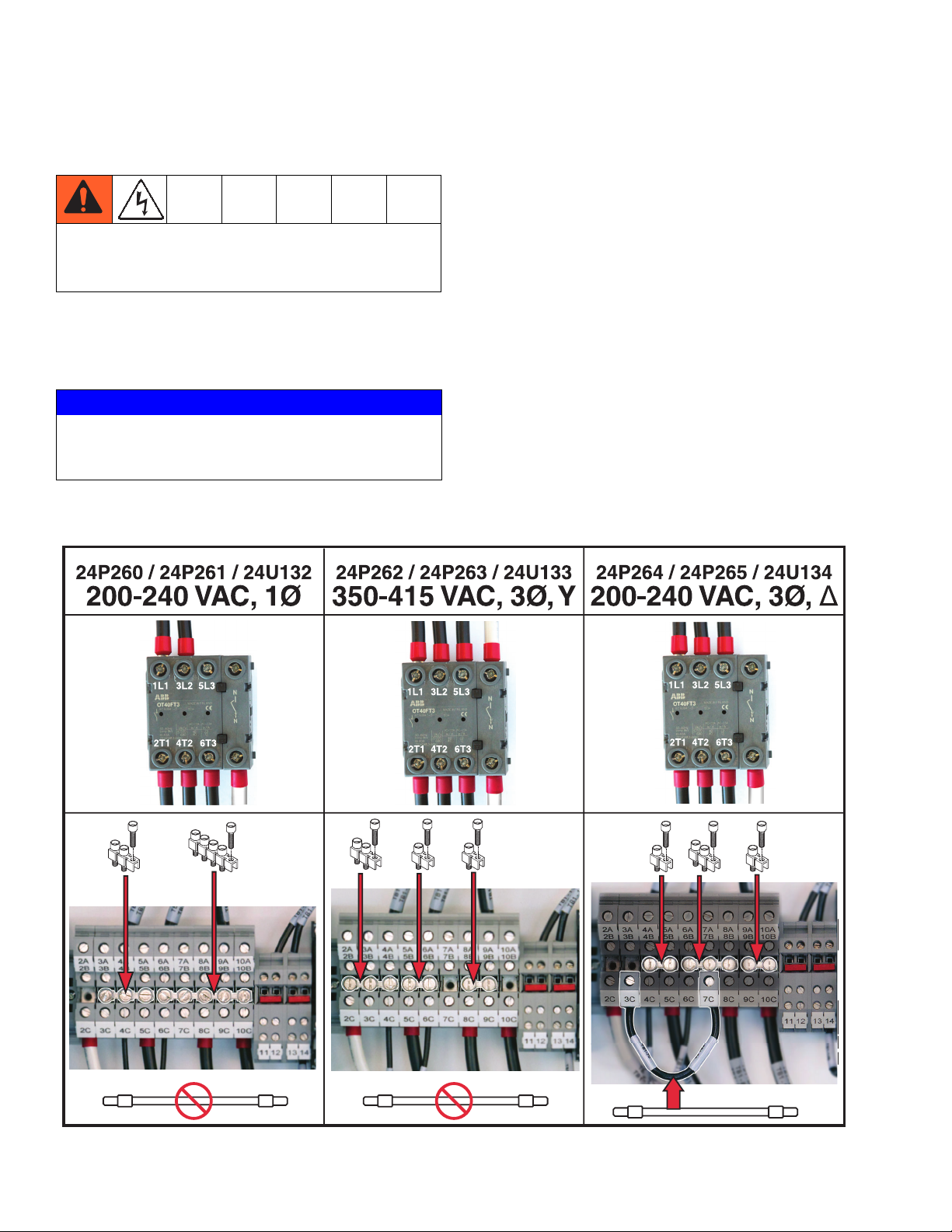
Electrical Schematics
Electrical Schematics
To prevent electric shock and system damage, all
electrical work must be performed by a qualified
electrician.
Incoming Power and Terminal
Jumpers
NOTICE
To prevent severe system damage, ensure terminal
jumpers are installed correctly. See Connect Electri-
cal Cord on page 19.
The incoming power and terminal jumpers are specific
to the phase and voltage used. The power type and circuit breaker size must be correctly set in the ADM. See
Select ADM Settings on page 21.
If changing power type, use the supplied hard metal 2,
3, and 5 terminal jumpers and screws and supplied
jumper wire to jumper the terminals. See Connect Elec-
trical Cord on page 19 for detailed information about
changing terminal jumper locations.
72 3A2347T
Page 73
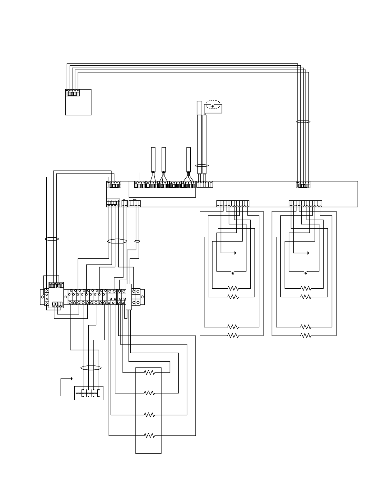
Systems with One MZLP Module
ADM
Level
Sensor
16T108
Solenoid
Optional Light Tower
RTD
16T103
Cycle Switch
Over-Temp
Switch
24R040
Electrical Schematics
16T089
Green
16T088
Red
PS1
L
J6
24R042
G
L2
L1
L3
MZLP 1
24V510
Black
16T200
L3
L2
L1
N
G
J1
J2
A1
CR1
NO
NC
G
COM
12
J7
16T199
A2
13
15
14
16
CHANNEL 1
J5
B
A
C
J8
Gun
Hose
F
D
E
Over-
Temp
Heater
Heater
G
H
J
GND
T°
T°
K
L
RTD
Gun
Hose
M
RTD
J3
K
M
F
B
D
H
C
Over-
Heater
Hose
Heater
E
Temp
G
J
GND
T°
T°
L
RTD
Gun
Hose
CHANNEL 2
RTD
A
J9
Gun
GB1
500W
Melter
24R034
GND
Pump
24R037
1500W
Band
24R039
1250W
Base
24R036
1000W
3A2347T 73
Page 74

Electrical Schematics
Systems with Two MZLP Modules
Green
Red
ADM
16T201
16T089
MZLP 2
L2
L1
24V510
G
L3
J2
CHANNEL 3
J6
Over
Gun
Heater
Hose
Heater
J8
Temp
GND
T°
T°
Gun
Hose
J3
J9
GND
Over
Temp
T°
Gun
Heater
Hose
Heater
Gun
T°
RTD
RTD
Hose
CHANNEL 4
RTD
RTD
RTD
Over-
Temp
Switch
16T087
Sensor
Level
16T108
14
15
Cycle Switch
16T103
J5
16
24R040
BDFHK
ACEGJ
J8
M
L
J6
ACEGJ
J9
BDFHK
M
L
Solenoid
24R029
Optional Light Tower
J3
J2
J1
MZLP 1
24V510
G
Black
L2
L3
L1
12
24R042
J7
13
16T088
PS1
L
16T200
L2
L1
G
N
CR1
NO
NC
16T199
COM
CHANNEL 1
Hose
Over-
Temp
Gun
Heater
Heater
GND
T°
T°
Gun
Hose
GND
Over-
Temp
Gun
Heater
Hose
Heater
T°
RTD
T°
Gun
Hose
CHANNEL 2
RTD
RTD
RTD
GB1
Melter
500W
GND
24R034
37
W
p
74 3A2347T
Page 75

Systems with Three MZLP Modules
Electrical Schematics
16W035
(16T089)
(16T088)
DRN
(24V510)
L1L2L3
MZTCM 1
(16T200)
J3
MZTCM 3
(24V510)
J6
SOLENOID J13-2,4
LEVEL SENSOR J14-1, 2, 4
(16T108)
(24P011)
J3
DH
-V
DL
+V
G
J1
(24R042)
(16T199)
J12
J7
J14
J13
CYCLE SWITCH J16-1, 4, 5
(16T103)
J16
J15
(16T106)
RTD Input
J5
OT Input
(16T087)
(24V510)
MZTCM 2
(16T087)
J3
J6
J2
(16W034)
(16T201)
J5
J2
-V
-V
OK
+V
+V
PS1
LNG
2
345
678
9
11
10
12
CR1
NC
NO
COM
14
13
TERMINAL BLOCK
NEU
L1
L2
L3
3A2347T 75
Page 76

Parts
Parts
InvisiPac Systems
System Parts, Page 1 of 3
30 58 29 8, 75 74, 82
44
3
28
8
43
39
7
3
69
43
27
8, 75
8, 75
ti20732a
45
43
2
Apply door gaskets (11) to door (10) per layout diagram.
5
Apply pipe sealant to all non-swiveling pipe threads.
7
Orient as shown.
76 3A2347T
Page 77

System Parts, Page 2 of 3
1
Torque to 5-11 ft-lb (7-15 N•m).
2
Apply door gaskets (11) to door (10).
3
Torque to 8-10 in-lb (0.9-1.1 N•m).
43
25
48
20
62
Parts
61
61a
26
83
12
13
13
5
8
7
3
53
24
1
52
2
11
41
3
1
42
10
40, 54
1
4
8
1
43
63
63
ti20733b
8
9
3A2347T 77
Page 78

Parts
System Parts, Page 3 of 3
35
41 in.
(1.04 m)
33
16 in.
(0.41 m)
57
34
48 in.
(1.22 m)
35
41 in.
(1.04 m)
36
13 in.
(0.33 m)
55
88
32
34
7 in.
(0.18 m)
64
66
65
34
2 in.
(0.05 m)
33
23 in.
(0.58 m)
35
41 in.
(1.04 m)
34
2 in.
(0.05 m)
87
66
64
34
48 in.
(1.22 m)
WLF
78 3A2347T
Page 79

Parts
System Parts
Ref Part Description
1 --- ENCLOSURE, electrical
3 115942 NUT, hex, flange head
4 167002 INSULATOR, heat; washer
5 24R375 MELTER AND PUMP
7 --- TRAY, drip
8 113161 SCREW, flanged, hex head
9 --- AIR CONTROLS ASSEMBLY
10 --- DOOR, front
11 --- FOAM, border, door
12* --- ADAPTER, melter inlet
13* --- CLAMP, hose, spacer
20 24R041 SENSOR, ultrasonic
22 --- SHAKER AND TUBE, feed system
24 116658 FITTING, tube, male, 1/4 npt
25◆ --- SWITCH, cycle
26◆ --- FASTENER, screw, pn hd M4 x 35 mm
27 --- BRACKET, back
28 --- COVER, filter
29 --- COVER, melter
30❄ 24P860 MODULE, Advanced Display (ADM)
31 117026 SCREW, socket head cap, M5 x 12
32† 112739 TEE, union
33† C12509 TUBE, nylon, round
34† --- HOSE, nylon, 3/8 in. OD, 250 psi (1.7
MPa, 17 bar)
35† 598095 TUBE, 5/32 in. OD, nylon
36† --- TUBE, PTFE, 1/4 in. OD
39 --- GROMMET, 1/4 in. ID
40 --- BUSHING, strain relief
41 --- GROMMET, wire
42 --- GROMMET, tube
43▲ 16U029 LABEL, safety
44 --- LABEL, InvisiPac
45 --- LABEL, pressure gauges
48 110932 CONNECTOR, male
49 C38321 STRAP, tie, cable
52 16T675 INSULATOR, melter manifold
53✖ 16T677 INSULATOR, melter
54 --- NUT, bushing
55 --- LABEL, identification
57 --- COUPLER, 3/8 in. OD tubing
58 --- BRACKET, mounting
61 24R738 FUNNEL, inlet, feed
61a 110932 CONNECTOR, male
62* --- MANIFOLD, feed inlet
63 121487 GROMMET, sheet metal, 3/4 in.
64 198177 FITTING, connector, male
65 --- FITTING, tee, 1/8 npt x 3/8 in. tube x
3/8 in. tube
66 --- RESTRICTOR, air, 0.0225 in. orifice
67 101976 TOOL, allen, wrench
68 255021 FITTING, straight, hydraulic
(assemblies 24P260, 24P262, 24P264
only; Qty 2)
(assemblies 24P261, 24P263, 24P265
only; Qty 4)
(assemblies 24U132, 24U133, 24U133
only; Qty 6)
Qty
15
3.25
4.92
6.75
1.3
10
Ref Part Description
69 114606 PLUG, hole
70 24R324 SOFTWARE UPGRADE TOKEN, Invi-
1
8
74 117126 SCREW, socket head cap, M5 x 16
4
75 16V153 WASHER, retaining
1
80 262907 FUNNEL SCREEN KIT (not shown)
1
82 117017 WASHER
83 16V540 INSULATOR, melter assembly
1
85 24V289 MZLP FUSES KIT (not shown)
1
86 24P176 I/O CONNECTOR KIT (not shown)
1
87 108982 CONNECTOR, tube
1
88 24R707 AIR INLET KIT
2
89 114271 RETAINING STRAP
1
1
1
1
1
1
1
92 127208 FITTING, tee, 6 JIC x 6 JIC x 9/16-18
1
1
2
93 FITTING, 45° elbow, hydraulic
1
94 116793 FITTING, elbow, hydraulic, 9/16-18 x
1
2
1
1
1
1
1
--- Not for sale.
1
▲ Replacement Danger and Warning labels, tags, and cards
1
1
2
1
1
1
1
1
1
3
2
1
2
1
are available at no cost.
❄ ADM does not come with software. Order software token
24R324.
Available kits (purchase separately):
Kit Description Includes
24R885◆ Cycle Switch 25, 26
24R028* Inlet housing 12, 13, 62
24R030† Tubing 32, 33, 34, 35, 36, 304. See
24R031✖ Melter 53, 202, 204, 207, 211, and
24U635 Acrylic Lens
siPac System
(assemblies 24P260, 24P262, 24P264
only; Qty 8)
(assemblies 24P261, 24P263, 24P265
only; Qty 16)
(assemblies 24U132, 24U133, 24U133
only; Qty 24)
(assemblies 24U132, 24U133, 24U133
only; Qty 2)
(assemblies 24P260, 24P262, 24P264
only; Qty 2)
(assemblies 24P261, 24P263, 24P265
only; Qty 4)
(assemblies 24U132, 24U133, 24U133
only; Qty 2)
9/16-18(assemblies 24P260, 24P262,
24P264 only; Qty 2)
(assemblies 24P261, 24P263, 24P265
only; Qty 4)
(assemblies 24U132, 24U133, 24U133
only; Qty 2)
Feed System Shaker and
Tube, 24T812 on page 85 for
identification of item 304.
253. See Melter and Pump
Parts on page 83 for identification of items 202-253.
Pressure Gauge
Qty
1
1
3
4
1
2
1
1
1
1
1
3A2347T 79
Page 80
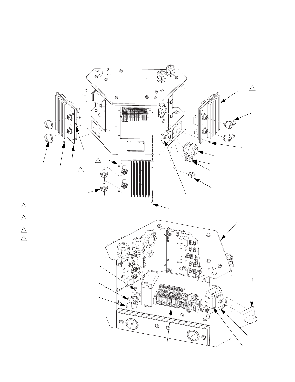
Parts
Electrical Enclosure
MZLP
113
1
Apply sealant to all non-swiveling pipe
threads.
2
Set rotary switch to “1” on MZLP with
daughter card.
3
Set rotary switch to “2” on MZLP 2.
4
Set rotary switch to “3” on MZLP 3.
114
112
112a
2
113
3
118
MZLP 2
114
109
MZLP 3
106, 107
120
110
108
118
114
WLD
101
4
113
131
132
117
111
104
102
80 3A2347T
WLE
105
Page 81

Parts
Electrical Enclosure Parts
Ref Part Description Qty
101 --- CABINET, controls 1
102 126807 MODULE, breaker 1
104 123970 SWITCH, disconnect, 40 amp 1
105 126839 CONTACT, n-pole 1
106 --- BUSHING, strain relief, M40 thread 1
107 --- NUT, strain relief, M40 thread 1
108 104641 FITTING, bulkhead 1
109 502937 FITTING, tee, 3/8 tube, 1/4 male
npt
110 114421 BUSHING, strain relief 1
111 117666 TERMINAL, ground 1
112* --- MODULE, MZLP with Daughter
Board
112a 24R042 MZLP DAUGHTER BOARD 1
113†✿16T440 CAP, jam nut, sealing
(1 MZLP assemblies only; Qty 2)
(2 MZLP assemblies only; Qty 4)
(3 MZLP assemblies only; Qty 6)
114 125856 SCREW, 8-32, serrated flange 12
116 24P175 PLATE, blank, single MZLP
(1 MZLP assemblies only; Qty 2)
(2 MZLP assemblies only; Qty 1)
117 115942 NUT, hex, flange head 1
118†✿✖24V510 MODULE, GCA, MZLP
(2 MZLP assemblies only; Qty 1)
(3 MZLP assemblies only; Qty 2)
119 --- GASKET, foam, MZLP
(1 MZLP assemblies only; Qty 2)
(2 MZLP assemblies only; Qty 1)
120 196762 PIN, straight 1
121†✿16T087 CABLE, board, male/male, 4 in.
(101 mm)
(2 MZLP assemblies only; Qty 1)
(3 MZLP assemblies only; Qty 2)
122 16T088 CABLE, power, male/wire 1
123 16T089 CABLE, CAN, male/female, 1 m 1
124 16T103 CABLE, pump 1
125◆ 16T106 SENSOR, band heater temperature 1
126 16T108 CABLE, ultrasonic, M12-4p, 1 m 1
129†✿16T201 HARNESS, 2nd MZLP
(2 MZLP assemblies only; Qty 1)
(3 MZLP assemblies only; Qty 1)
130 114958 STRAP, tie 4
Ref Part Description Qty
131 113974 SCREW, machine, slotted hex
washer head
132 123967 KNOB, operator disconnect 1
133 24P176 KIT, Customer I/O connector 1
134✿ 16W034 HARNESS, 3rd MZLP 1
135✿ 16W035 CONNECTOR, jumper 1
--- Not for sale.
1
Available kits (purchase separately):
Kit Description Includes
24R237† Upgrade from 2
1
channel system to 4 channel system
113, 118, 121, 129, a
grounding wrist strap, and a
software upgrade token.
See 4 Channel Upgrade
Kit, 24R237 on page 96.
24U575✿ Upgrade from 4
channel system to 6 channel system
113, 118, 121, 129,134,
135, grounding wrist strap,
and a software upgrade
token. See 6 Channel
Upgrade Kit, 24U575 on
page 98.
24R040◆ RTD 125, 251, and 255. See
Melter and Pump Assembly, 24R375 on page 82.
24V289 MZLP fuses Qty 8 - 8 Amp, 250V Fuses
Qty 2 - 16 Amp, 250V
Fuses
24P176 Customer I/O
Connectors
2 connectors for connecting to H1 and H2 on MZLP
daughter board. Use for
PLC connection.
* Purchase MZLP (118) and daughter board (112a)
separately.
✖ Use Blank Plate Kit (116) if removing MZLP (118).
2
3A2347T 81
Page 82
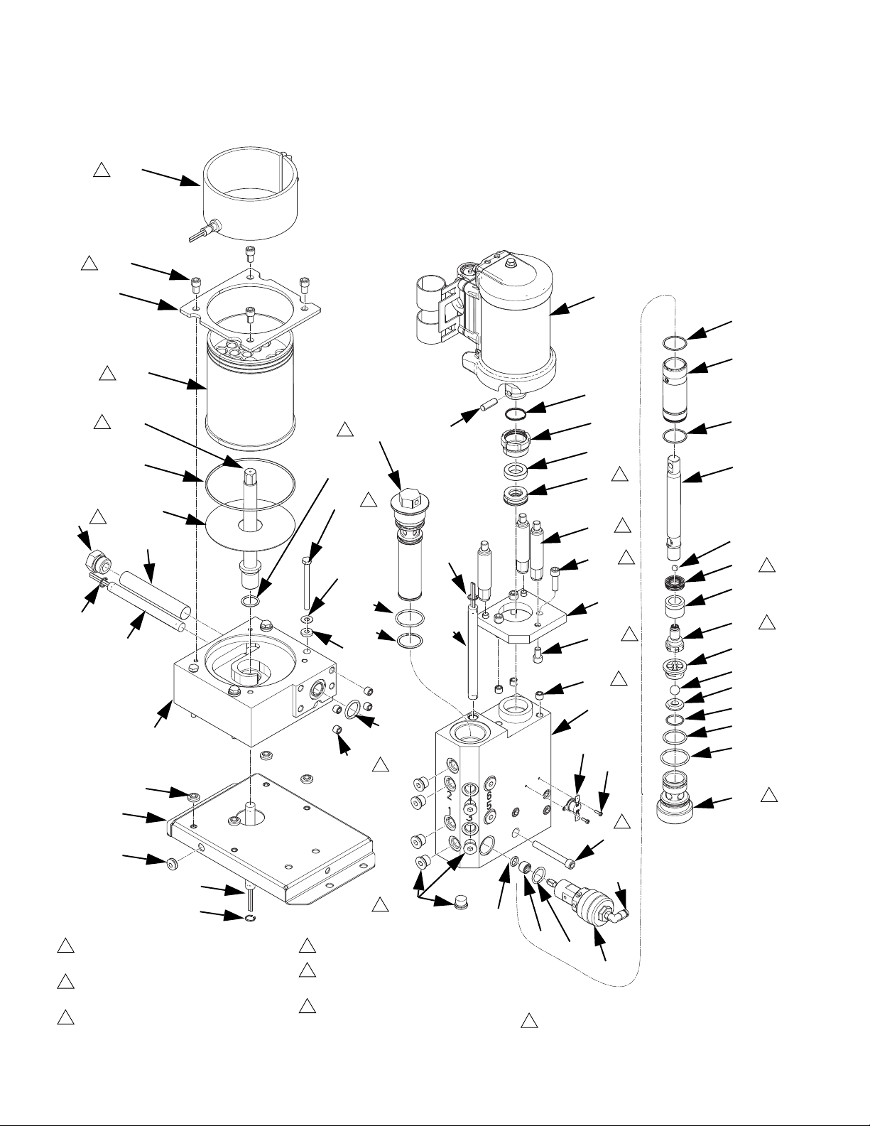
Parts
Melter and Pump Assembly, 24R375
208
2
211
8
204
202
2
4
205
207
215
253
8
213
206
210
201
249
257
258
209
206
1
Lubricate all seals and o-rings with
grease.
2
Orient melter (202) sensor hole in line
with band heater (208) clamp.
3
Torque to 5-11 ft-lb (7-15 N•m).
4
236
238
254
259
3
206
260
232
237
250
249
214
252
7
247
8
4
Torque to 24-30 ft-lb (33-41 N•m).
5
Orient u-cups (225, 234) with springs
in direction shown.
7
Assemble inserts (252) 0.01-0.05 in.
(0.3-1.3 mm) below surface.
242
218
239
235
233
234
5
220
3
240
3
219
211
8
252
7
203
251
255
8
246
245a
243
244
245
8
Torque to 12-18 ft-lb (16-24 N•m).
ti20739b
217
216
217
223
224
225
226
222
221
227
228
229
231
232
230
5
4
4
82 3A2347T
Page 83

Parts
Melter and Pump Parts
Ref Part Description Qty
❄
201
--- MANIFOLD, melter base 1
202✖ --- MELTER 1
203• --- MANIFOLD, outlet 1
204✖ --- PLATE, mounting 1
205 --- HOUSING, heater 1
206• 111317 RING, retaining, internal 3
207✖ 126475 O-RING, FKM, 157 1
208 24R039 HEATER, band 1
209 24R034 HEATER, fire rod, 500 watts 1
210 24R036 HEATER, fire rod, 1000 watts 1
211✖ 116940 SCREW, cap, sh, 5/16-18, 0.5 in.
long
213 24R369 INLET FILTER 1
❄
214•
112855 PACKING, o-ring 1
215 24T297 PLUG, o-ring boss 1
216ॠ--- SLEEVE, cylinder 1
217†‡• 108526 PACKING, o-ring, PTFE 2
218✓ 24R025 MOTOR, air, 2.5 in., 0.48 in.
stroke, high temperature
219 --- PLATE, pump adapter 1
220 --- ROD, tie 3
221• 192624 GUIDE, ball 1
222◆• 239932 VALVE, piston 1
223◆• --- ROD, piston 1
224†◆• 105444 BALL, 0.3 in. 1
225†◆• --- SEAL, u-cup, piston 1
226†◆• --- BEARING, piston 1
227†• 105445 BALL, 0.5 in. 1
228†• 192642 SEAT, carbide 1
229†• 107079 PACKING, o-ring 1
230• --- HOUSING, foot valve 1
231• 105802 PACKING, o-ring 1
232†❖• 113944 PACKING, o-ring 2
233†• --- BEARING, throat 1
234†‡• --- SEAL, u-cup, throat 1
235• 193046 NUT, packing 1
236❖• --- FILTER, assy, 100 mesh 1
237❖• 15K234 PACKING, o-ring 1
238✓ 196762 PIN, straight 1
239✓ 196750 SPRING, retaining 1
240 101864 SCREW, socket head cap,
5/16-18, 1.0 in long
242★• 117059 O-RING, fluoroelastomer 1
243★• 16W327 RETAINER, seat, dump valve 1
244★• 15Y627 PACKING, o-ring #2-116, PTFE 1
245★• --- VALVE, relief 1
245a 126474 FITTING, push to connect 1
246• 121295 SCREW, cap, socket head,
5/16-18, 2.5 in. long
247• 15H304 FITTING, plug 9/16 in. SAE 5
Ref Part Description Qty
249 167002 INSULATOR, heat 10
250• 24R037 HEATER, fire rod, 1500 watts 1
251**• --- SWITCH, over temperature 1
❄
252•
--- INSERT, helical 7
253✖ --- PLATE, melter 1
254 558722 O-RING, 910 1
255**• 107388 SCREW, machine, panhead,
#4-40, 3/8 in. long
256 --- LUBRICANT, grease 1
257 --- BRACKET, melter 1
258 --- GROMMET, 1/4 in. ID 1
259 115506 SCREW, machine, hex washer
7
head, 1/4-20, 3.0 in. long
260 115814 WASHER, flat 3
297* 120663 FITTING, straight, hydraulic 1
298* 126961 FITTING, 45 deg. elbow, hydraulic 1
299* 116793 FITTING, 90 deg. elbow, hydraulic 1
* Not shown or assembled. Quantity equals number of chan-
1
3
4
nels the unit supports.
--- Not for sale.
Available kits (purchase separately):
Kit Description Includes
24P852† Pump repair 217, 224, 225, 226, 227, 228,
229, 232, 233, 234, and seal
installation tool 15B661.
24P853‡ Cylinder 216, 217, 234, and seal instal-
lation tool 15B661.
24P854◆ Pump rod 222, 223, 224, 225, 226
24P855❖ 100-mesh filter 232, 236, 237
24P856★ Pressure relief
valve
24R025✓ Air motor 218, 238, 239
24R031✖ Melter 202, 204, 207, 211, 253, and
24R040** RTD 125, 251, and 255. See Elec-
24R709 • Assembled pump
manifold
24W594❄ Melter base kit 201, 214, 254, 252
24W595 Filter rebuild kit See Filter Rebuild Kit,
--- Special tools See Special Tools on page
242, 243, 244, 245
insulator (53). See InvisiPac
Systems parts starting on
page 76 for insulator (53)
identification.
trical Enclosure on page 80.
203, 206, 214, 216, 217, 221,
222, 223, 224, 225, 226, 227,
228, 229, 230, 231, 232, 233,
234, 235, 236, 237, 242, 243,
244, 245, 246, 247, 250, 251,
252, 255
24W595, page 103
89.
2
4
3A2347T 83
Page 84
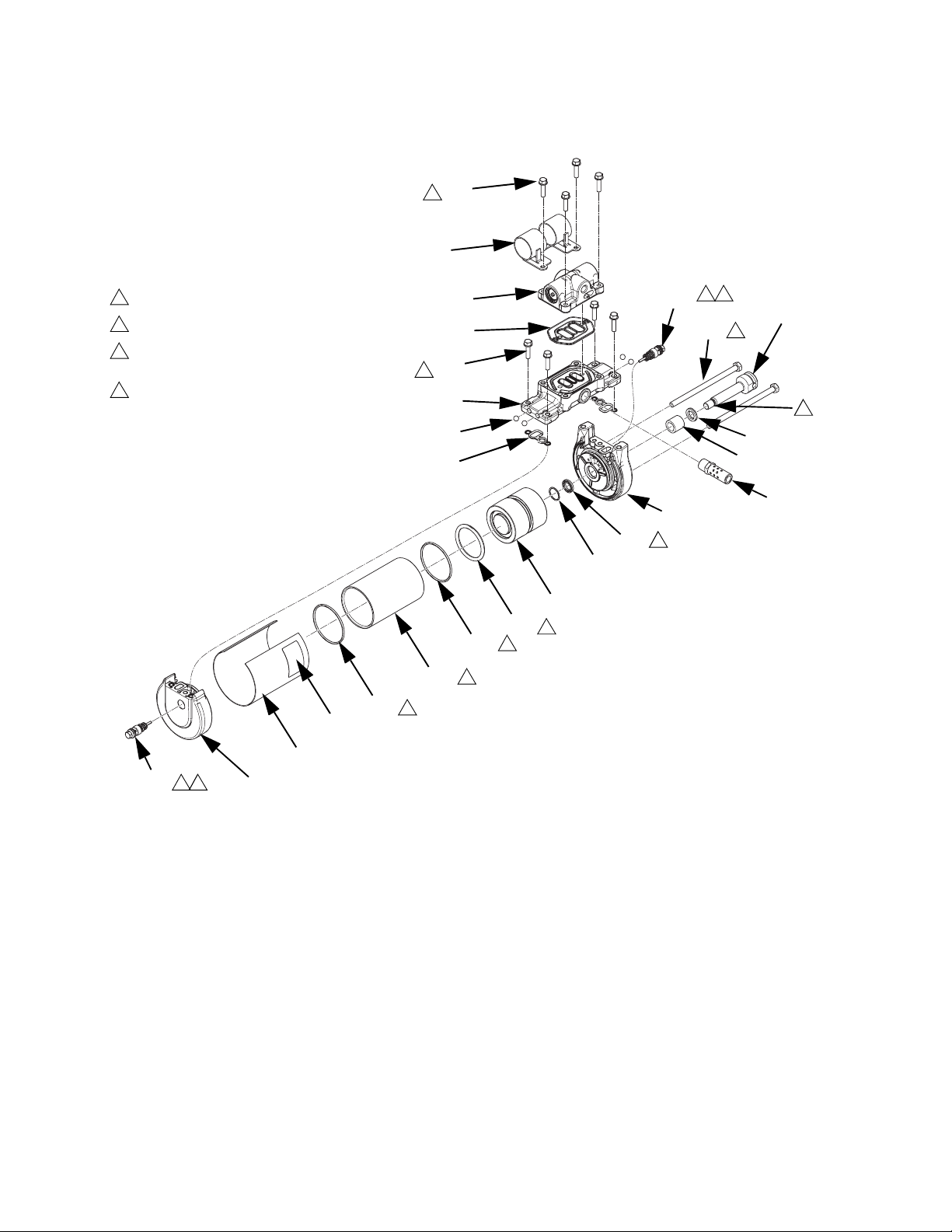
Parts
Air Motor, 24R025
1
Torque to 11-13 ft-lb (15-18 N•m).
2
Apply water-resistant grease.
3
Apply epoxy adhesive then torque to
35-40 ft-lb (47-54 N•m).
4
Torque to 95-105 in-lb (10.7-11.9 N•m).
4
528
4
511
527
511
520
522
508
509
513
2 4
512
518
1
3
507
503
502
2
523
506
513
2 4
510
24R025 Parts
Ref Part Description Qty
501 --- COVER, lower, 2.5 in. 1
502◆ 108993 PACKING, o-ring 2
503 --- BEARING, 9/16 in. 1
504★◆ --- PACKING, o-ring, FKM 1
505 15M289 CYLINDER, motor, 2.5 in. 1
506 --- COVER, air motor 1
507◆ --- SEAL, u-cup, FKM 2
508◆ --- GASKET, cover, small 2
509†◆ --- SEAL, air valve, manifold 1
510 15M291 COVER, motor, 2.5 in. 1
511† --- SCREW, M6 x 25, thread forming 8
512 15M314 SCREW, cap 2
513 24R027 VALVE, pilot 2
515 15M213 MUFFLER, 3/8 1
516 --- GREASE, water-resistant 1
517◆ --- RING, retaining 1
518★ --- ROD, air motor, 2.5 in. 1
519★ --- PISTON, air motor, 2.5 in. 1
501
507
2
517
519
504
2
502
2
505
2
ti20903a
Ref Part Description Qty
520 --- MANIFOLD, medium, short 1
521★◆ --- ADHESIVE 1
522 105444 BALL, 0.3 in. 4
523 --- LABEL, identification 1
527† 24R026 VALVE, air, small 1
528 --- BRACKET, feed inlet assembly 1
-
-- Not for sale.
★ Included in Air Motor Piston Kit 24R705 (purchase sepa-
rately.
◆ Included in Air Motor Seals Kit 24R706 (purchase separately).
† Included in Air Motor Valve Kit 24R026 (purchase sepa-
rately).
515
84 3A2347T
Page 85
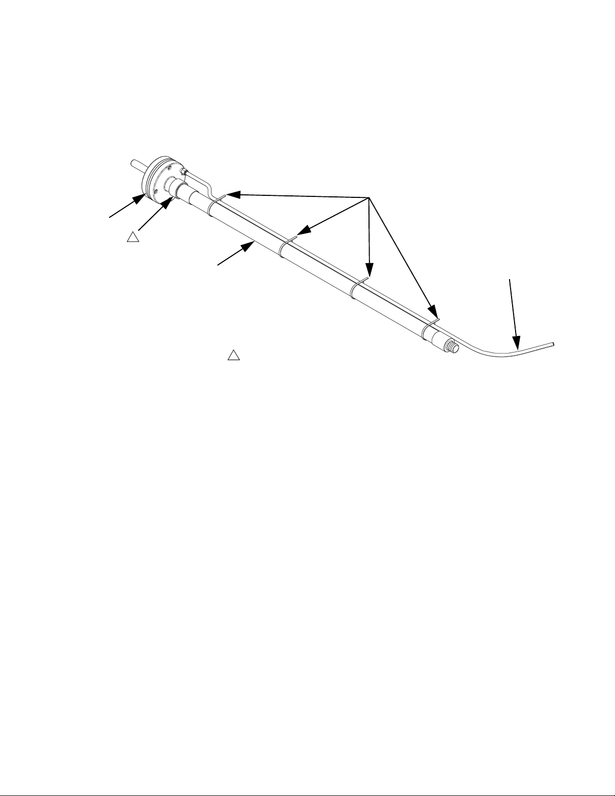
Feed System Shaker and Tube, 24T812
301
1
Parts
306
302
1
Apply pipe sealant to threads.
Parts
Ref Part Description Qty
301 24P861 SHAKER 1
302 24N954 TUBE, steel 1
303†◆ --- TUBE, clear PVC, 1.3 in.
(33 mm) OD
304 --- HOSE, nylon, 3/8 in. OD,
15.5
250 psi (1.7 MPa, 17 bar)
305◆ 125370 CLAMP, hose, dia. 11/16 to
1-1/2 in.
306 125871 TIE, cable, 7.50 in. (190 mm) 4
--- Not for sale.
10
304
† 30 ft (9.1 m) Feed Hose Kit 24R043 also available
(purchase separately). Kit also includes 2 hose
clamps.
★ Included in Tubing Kit 24R030. See System Parts
on page 79 for other kit contents.
◆ Not shown.
3
NOTE: Shaker Grounding Kit 24R708 (purchase separately) also available. Kit includes a grounding wire
assembly, and a screw and washer for installing on the
shaker tube (301).
ti20738a
3A2347T 85
Page 86

Parts
Air Controls Assembly
405
402
404
1
401
403
1
Apply sealant to all non-swiveling pipe threads.
Air Controls Assembly Parts --- Not for sale.
406
404
1
ti20737a
Ref Part Description Qty
401 --- PANEL, air, controls 1
402 24R029 CONTROL, air, vacuum trans-
fer and pump
403 15T500 GAUGE, pressure, air, panel
mount, 1/8 in. npt
404 15T498 FITTING, 90 degree, swivel,
5/32 in. tube x
1/8 in. female npt
405 100058 SCREW, cap, hex head 2
406 054753 TUBE, nylon, round, black 2
1
2
2
86 3A2347T
Page 87
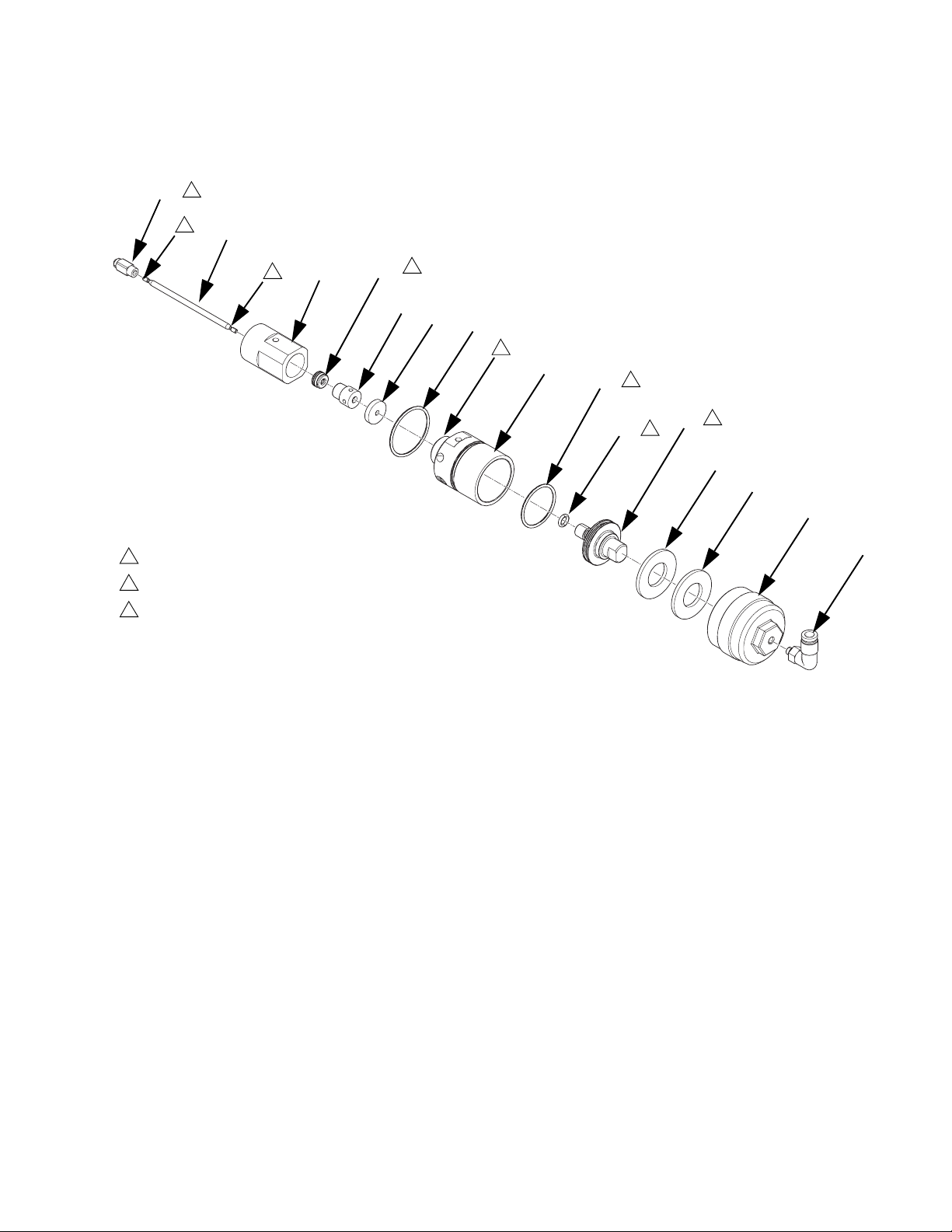
Pressure Relief Valve, 24P856
607
3
1
606
614
1
601
2
605
611
608
Parts
1
602
609
2
603
612
2
3
610
610
604
1
Apply sealant to all non-swiveling pipe threads.
2
Apply grease.
3
Torque to 4-6 in-lb (0.5-0.7 N•m).
Ref Part Description Qty
601 --- BODY, fluid 1
602 --- BODY, air 1
603 15T413 PISTON, air 1
604 --- AIR CAP, valve 1
605 --- BEARING, shaft, needle 1
606 --- SHAFT, needle, valve 1
607 --- SOCKET, ball assembly 1
608† 108771 PACKING, o-ring 1
613
Ref Part Description Qty
609† 110073 PACKING, o-ring 1
610 111841 WASHER, plain 5/8 in. 2
611† --- BEARING, valve 1
612† --- O-RING, FKM 1
613 126474 FITTING, push to connect 1
614† --- SEAL, u-cup, relief valve 1
--- Not for sale.
† Parts included in Relief Valve Repair Kit 24P857
(purchase separately).
3A2347T 87
Page 88
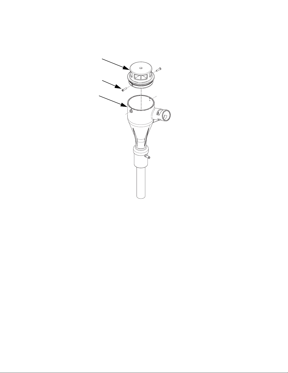
Parts
Feed Inlet Funnel, 24R738
701
705
706
Ref Part Description Qty
701 262907 FILTER AND CAP ASSEMBLY 1
705 --- SCREW, #10-16, thread forming 2
706 --- FUNNEL, feed inlet 1
ti20927b
--- Not for sale.
88 3A2347T
Page 89
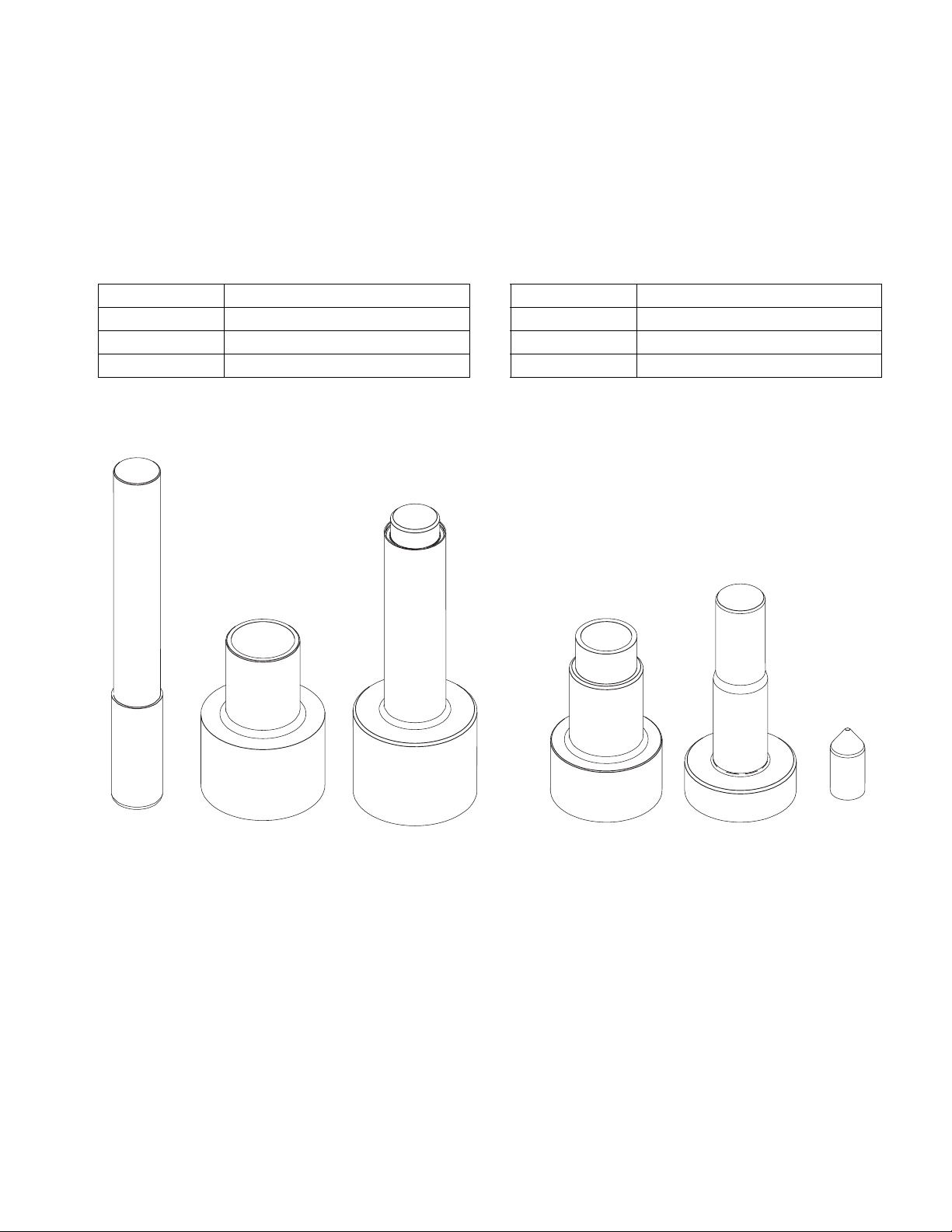
Accessories
Accessories
Special Tools
These special tools are designed to make system repairs as easy as possible while ensuring that parts do not get
damaged.
Part Purpose
1301* Remove Cylinder
1302* Install Cylinder - Female
1303* Install Cylinder - Male
* Parts included in Cylinder Tools Kit 24R227 (pur-
chase separately).
Part Purpose
1304** Install Rod - Female
1305** Install Rod - Male
1306** Install Rod - Bullet
** Parts included in Rod Tools Kit 24R228 (purchase
separately).
ti20983a
3A2347T 89
Page 90

Accessories
Non-Graco Gun Adapter Cables
16T916: For connecting to non-Graco guns that use a
rectangular, 6-pin connector.
ti21128a
16T917: For connecting to non-Graco guns that use a
circular, 9-pin connector.
Air Adjustment Lock, 24R084
Panel enables locking access to the air adjustment
screws.
801
ti21129a
16Y828: For connecting to non-Graco guns that use a
circular 6-pin connector. IPx6 rated.
WLD
Non-Graco Gun Adapter Cable Installation
See Attach Components on page 14.
ti20984a
NOTE: Screws are part of the base system and are
not included in the kit.
Ref Part Description Qty
801 --- PANEL, lock, air control 1
802 --- BRACKET, lock, air control 1
802
Air Adjustment Lock Installation
1. Remove screws from system air panel.
2. Use screws to install panel (801).
3. Snap bracket (802) into panel (801).
4. Insert lock through hole in panel and bracket to lock
access to the air controls. Lock not included in kit.
90 3A2347T
Page 91
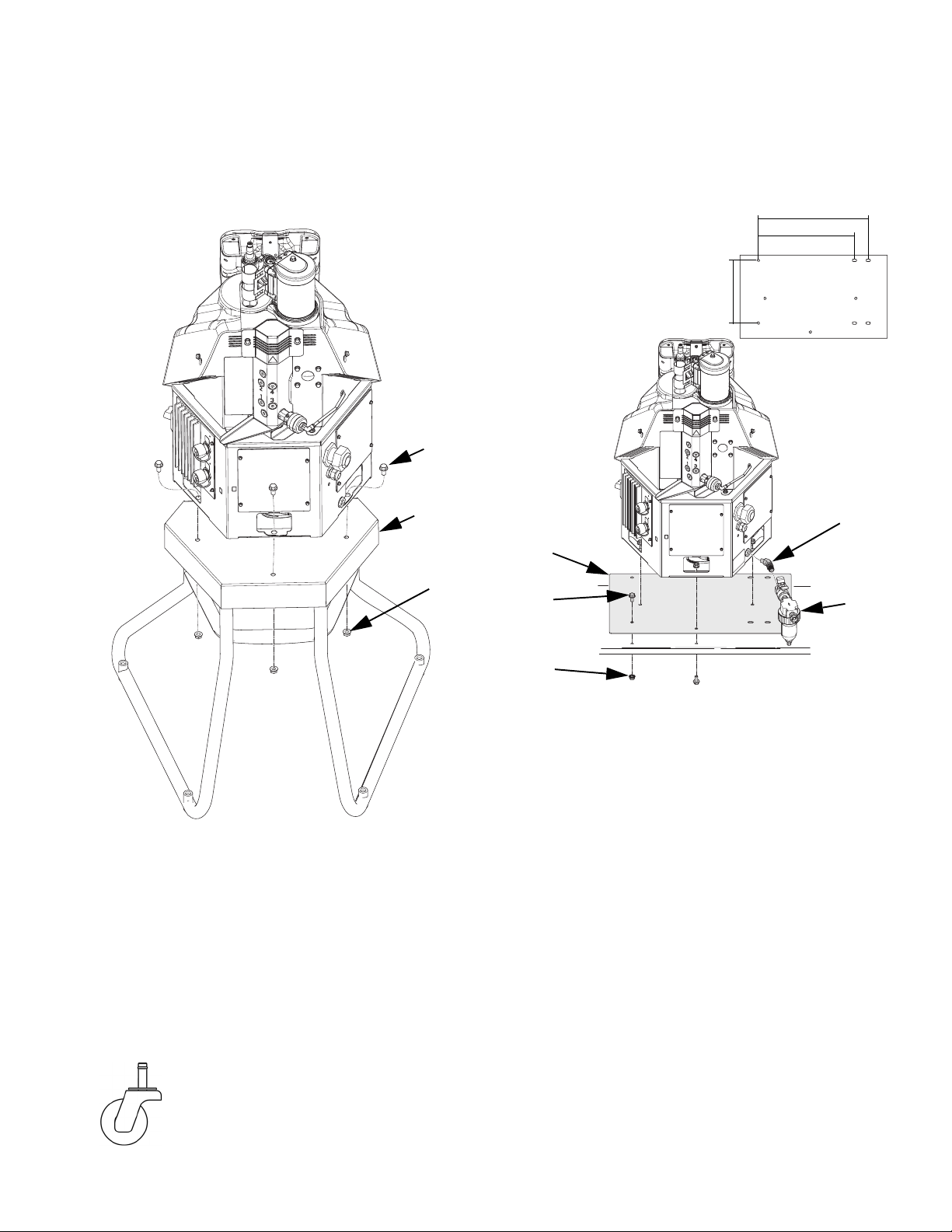
Accessories
System Stand, 24R088
Use the stand to mount the system at eye level. When
the system is mounted on the stand, the ADM is 45 in.
(1.14 m) above the bottom of the stand.
1002
1001
1003
Adapter Plate, 24R083
Use this adapter plate to install InvisiPac in place of an
existing hot melt applicator system.
C
Bolt Hole Dimensions
A 9.8 in. (249 mm)
B 14.843-15.157 in.
(377.0-385.0 mm)
C 17.003-17.317 in.
(431.9-439.9 mm)
1101
1102
A
B
1104
A
ti20985a
Ref Part Description Qty
1001 --- STAND 1
1002 112395 SCREW flange head cap 3
1003 112958 NUT, hex, flanged 3
System Stand Installation
1. Place stand (1001) in desired location.
2. Use bolt holes to bolt stand in place.
3. Place system on stand.
4. Use screws and nuts to secure system to stand.
Caster for Stand, 120302
Caster with friction post mounts directly to
system stand using no extra hardware. Four
required. Casters raise stand an additional
4.25 in. (108 mm).
1103
Ref Part Description Qty
1101 --- PLATE, adapter 1
1102 112395 SCREW flange head cap 6
1103 112958 NUT, hex, flanged 9
1104 121283 FITTING, elbow, 45 degree 1
ti21918a
Adapter Plate Installation
1. Remove existing hot melt applicator system.
2. Use six screws (1102) and six nuts (1103) to secure
adapter plate (1101) through the existing holes from
the previous system.
3. Align the InvisiPac system with the bolts on the
adapter plate (1101) then place onto the adapter
plate (1101).
4. Use the remaining three nuts (1103) to secure the
InvisiPac system to the adapter plate (1101).
5. Use elbow fitting (1104) to install system air inlet
filter (A, not included with kit).
3A2347T 91
Page 92

Accessories
30 Gallon Vibrating Hopper, 24R136
Hopper includes a shaker to ensure the adhesive pellets maintain a level surface at all times. Without this, the adhesive pellets can stick together, preventing them from continuously covering the vacuum transfer system’s inlet. This
would cause the vacuum transfer system to be unable to transfer the adhesive pellets.
Input Air Pressure Requirement: 100 psi (7 bar, 0.7 MPa)
Air Consumption: 17.1 scfm (29.1 cubic meters per hour)
902
903
910
901
905
ti20928a
Ref Part Description Qty
901 --- HOPPER, 30 gallon 1
902 --- LID, hopper, 30 gallon 1
903 126930 SHAKER, ball vibrator 1
904 126929 VALVE, air pilot, 3-way, closed 1
905 --- BRACKET, shaker, container 1
907 --- HOSE, nylon, 3/8 in. OD, 250 psi
(1.7 MPa, 17 bar)
908 119798 CONNECTOR, tee, push-tube 1
909 113779 MUFFLER 1
910 111192 SCREW, cap flange head 2
903
907
Ref Part Description Qty
912 125857 SCREW, 10-24, serrated flange 4
914* 121141 FITTING, elbow, swivel, 3/8 in.
915 120389 FITTING, tube 2
916 --- CONNECTOR, tube, 90 degree 1
917 125539 FITTING, splitter, 3/8 in. OD tub-
1
--- Not for sale.
* Metric fitting included in Air Metric Fitting Kit,
24W637, page 103.
915
915
904
909
914*
tube connector, 1/4 male npt
ing
916
912
1
1
92 3A2347T
Page 93

Accessories
30 Gallon Vibrating Hopper Installation
See FIG. 56 for illustration of installed vibrating hopper.
1. Turn main power switch OFF.
2. With the steel shaker rod fully assembled and the
3/8 in. OD air line connected to the shaker head, cut
the 3/8 in. OD air line where the 1.3 in. clear vacuum transfer hose connects to the steel shaker rod.
3. Use the splitter fitting (917) to reconnect the 3/8 in.
OD air line that was just cut.
4. Install the 48 in. section of 3/8 in. OD hose supplied
with the kit into the remaining connection on the
splitter fitting (917).
5. Connect the other end of the 48 in. section of 3/8 in.
OD air line to elbow fitting (916) on the piloted air
valve.
6. Connect shop air to elbow fitting (914) on the piloted
air valve. Shop air must be capable of 100 psi
(0.7 MPa, 7 bar).
NOTE: The air supplied to the pilot valve from the system vacuum must be set to 65% of the shop air supply
supplied to elbow fitting (914) or higher. If the pilot valve
air pressure is lower than this, increase the vacuum
transfer air pressure regulator (E, see F
IG
. 1 on page 8).
Splitter fitting
To piloted
air valve
To shaker
head
NOTE: The piloted air valve must use shop air. Adding a
tee at the system inlet to run the hopper shaker may
impact pump and vacuum transfer performance.
7. Place steel shaker rod assembly into hopper (901)
with steel rod resting in the hopper groove in the rim
of the hopper.
8. Place lid (902) on hopper (901).
NOTE: The hopper shaker will be active while the vacuum transfer system is transferring pellets.
Hopper
shaker
Piloted air
valve
To shop air
supply
ti21350a
FIG. 56
3A2347T 93
Page 94

Accessories
Light Tower Kit, 24R226
The light tower enables someone away from the system to quickly see whether the system is inactive or OFF (no
lights), warming up (flashing green), at temperature (solid green), or has an active error (red).
1201
1201a
1203
BB
1202
1205
24R226 Parts
Ref Part Description Qty
1201 16T102 LIGHT, tower, red and green 1
1201a --- SCREW 3
1202 --- GROMMET, single cable 1
1203 16K322 BRACKET, light tower 1
1204 --- GROMMET, multiple wires 1
1205 125835 CLIP, ferrite bead 1
AA
1204
J12
J1
F1
F2
F3
F4
J2
F5
F6
F7
F8
F9
F10
J3
J5
J6
J7
ti20987b
--- Not for sale.
94 3A2347T
Page 95

Accessories
Light Tower Kit Installation
1. Turn main power switch OFF.
2. Disconnect cable from ADM, push cable through
plastic shroud, then remove shroud from system.
3. Remove existing grommet (AA) from electrical
enclosure then install new grommet (1204) in its
place.
4. Insert grommet (1202) into hole on the light tower
bracket (1203).
5. Remove bolts (BB) from metal shroud on the system then use the bolts (BB) to secure
bracket (1203) to metal shroud.
6. Route light tower cable through hole in
bracket (1203) then use supplied light tower
screws (1201a) to install light tower (1201).
7. Remove electrical enclosure front access door.
Air Reservoir Kit, 16W366
This kit allows the system to operate as low as 60 psi
(0.4 MPa, 4 bar).
1505
1503
1504*
1504
8. Route light tower cable through the other hole in the
bracket (1203), then through the grommet (1204)
into the electrical enclosure.
9. Connect light tower cable to MZLP connector
labeled J12.
1505
1506
1501
16W366 Parts
Ref Part Description Qty
1501 --- HOSE, nylon (6 ft) 1
1502 100081 BUSHING, pipe 1
1503 113777 TEE, branch 1
1504* 114485 CONNECTOR, male, 3/8 npt 2
1505 155665 UNION, adapter 1
1506 --- TANK, air, accumulator 1
--- Not for sale.
* Metric fitting included in Air Metric Fitting Kit,
24W637, page 103.
3A2347T 95
Page 96
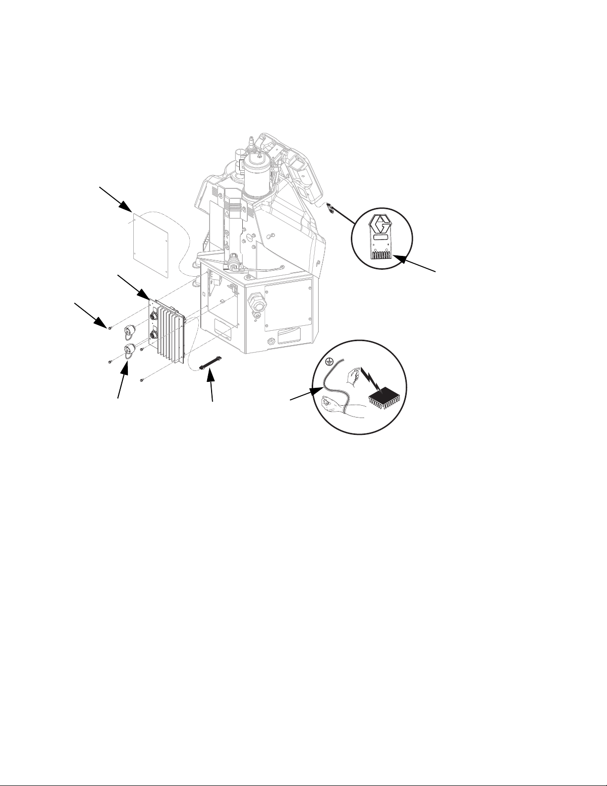
Accessories
4 Channel Upgrade Kit, 24R237
Use this kit to upgrade a 2 channel system to a 4 channel system.
AA
1301
BB
1305
Ref Part Description Qty
1301 --- MODULE, GCA, MZLP 1
1302 16T087 CABLE, jumper, male/male, 4 in. 1
1303 16T201 HARNESS, 2nd MZLP power 1
1304 112190 STRAP, wrist, grounding 1
1305 16T440 CAP, jam nut, sealing 2
1306 24R324 SOFTWARE UPGRADE
TOKEN, InvisiPac System
1302
1304
1306
ti20988a
◆ Not shown.
1
96 3A2347T
Page 97
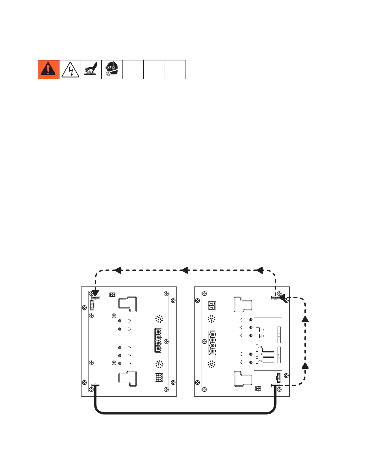
4 Channel Upgrade Kit Installation
Accessories
1. Disconnect plug from power outlet or turn off circuit
breaker for incoming power.
2. Place grounding wrist strap (1304) over your wrist
and secure other end to a grounded surface.
3. Set MZLP rotary switch to “1” on MZLP with daughter card.
4. Set MZLP rotary switch to “2” on MZLP without
daughter card.
5. Remove screws (BB) then remove plate (AA) from
system.
6. Use screws (BB) to install MZLP (1301) onto system.
NOTE: The new MZLP (1301) with be referred to as
MZLP 2, and the original MZLP that came with the system will be referred to as MZLP 1 from here on. See F
IG
57.
Step 8: Move CAN Connector (DD).
7. Remove electrical enclosure front access door.
NOTE: Do not force the electrical connection. Minimal
force is required to seat the connector. If resistance is
felt, stop and verify the connector orientation.
8. Move CAN connector from MZLP 1 connector J3 to
MZLP 2 connector J6. See F
IG
. 57.
9. Move power cable (CC) from MZLP 1 connector J6
to MZLP 1 connector J3. See F
IG
. 57.
10. Connect jumper cable (1302) to MZLP 1 connector
J6 and connect other end of jumper cable (1302) to
MZLP 2 connector J3. See F
IG
. 57.
11. Connect wires from power harness (1303) to connectors as labeled on the plastic connector.
12. Connect power harness (1303) to MZLP 2 connec-
.
tor J2.
MZLP 2
J6
J5
MZLP 1
J1
J3
Step 9:
J9
J2
J8
Move
Power
Cable
(CC).
J2
J8
J1
J9
J3
J5
J6
ti20989a1
Step 10: Install Jumper Cable (1302).
FIG. 57
3A2347T 97
Page 98
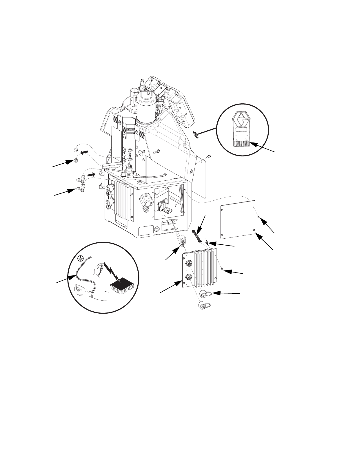
Accessories
6 Channel Upgrade Kit, 24U575
Use this kit to upgrade a 4 channel system to a 6 channel system.
CC
1304
1308
WLD
1306
1303
1301
Ref Part Description Qty
1301 --- MODULE, GCA, MZLP 1
1302 16T087 CABLE, jumper, male/male, 4 in. 1
1303 112190 STRAP, wrist, grounding 1
1302
BB
1307
AA
BB
1305
Ref Part Description Qty
1304 24R324 TOKEN, software upgrade 1
1305 16T440 CAP, jam nut, sealing 2
1306 16W034 HARNESS, MZLP #3 1
1307 16W035 CONNECTOR, jumper 1
1308 127208 FITTING, tee 2
98 3A2347T
Page 99
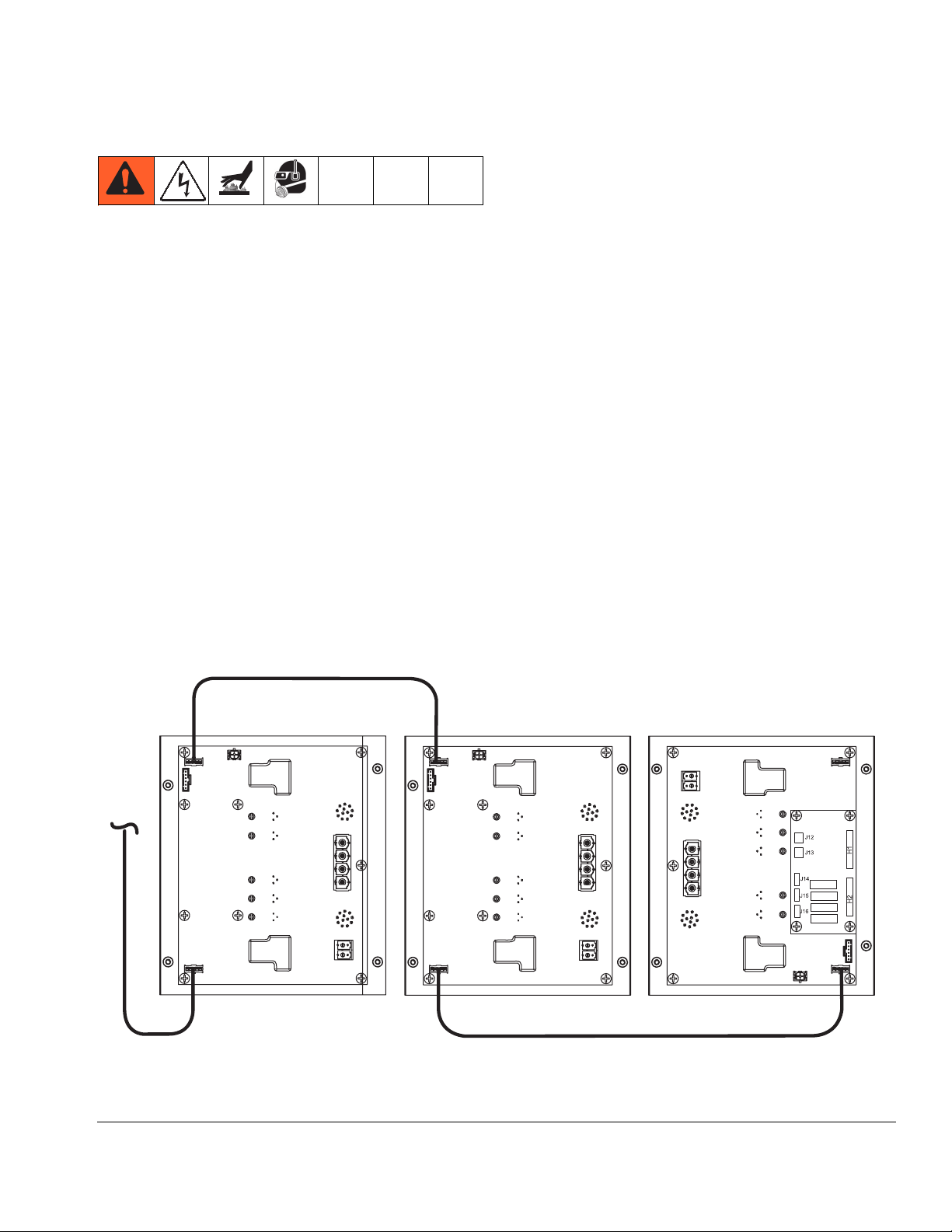
6 Channel Upgrade Kit Installation
Accessories
1. Disconnect plug from power outlet or turn off circuit
breaker for incoming power.
2. Place grounding wrist strap (1303) over your wrist
and secure other end to a grounded surface.
3. Set MZLP (1301) rotary switch to “3”.
4. Remove screws (BB) then remove plate (AA) from
system.
5. Use screws (BB) to install MZLP (1301) onto system.
6. Remove electrical enclosure front access door.
NOTE: Do not force the electrical connection. Minimal
force is required to seat the connector. If resistance is
felt, stop and verify the connector orientation.
7. Move ADM CAN connector from MZLP 2 connector
J6 to MZLP 3 connector J3. See F
IG
. 58.
Step 8: Install jumper cable (1302).
8. Connect CAN jumper cable (1302) to MZLP 2 connector J6 and connect other end of jumper
cable (1302) to MZLP 3 connector J6. See F
IG
. 58.
9. Install jumper connector (1307) in J5 on MZLP 3.
10. Connect wires from power harness (1306) to connectors as labeled on the plastic connector.
11. Connect power harness (1306) to MZLP 3 connector J2.
12. Remove plugs (CC) from fluid manifold and replace
with tee fittings (1308).
NOTE: The new MZLP (1301) will be referred to as
MZLP 3, and the original MZLPs that came with the system will be referred to as MZLP 1 and MZLP 2 from here
on. See F
IG
. 58.
0=/3
-
-
7R
$'0
-
Step 7: Move ADM CAN connector.
FIG. 58
-
-
-
-
-
-
-
0=/3
-
-
-
-
-
-
-
-
0=/3
-
-
-
WLD
3A2347T 99
Page 100

Accessories
Single-Phase 480V to 240V Transformer, 24U169
This transformer must be installed by a qualified electrician to operate 240V InvisiPac units with single-phase
480V electrical supply.
NOTE: When using transformer 24U169, the ADM amp
limit must be set to 30 amps and power type set to single phase. See step 4 of Select ADM Settings on page
21.
24U169 Electrical Specifications:
Phase: Single
Frequency: 60 Hz
kVa: 7.5 kVa
K Rating: 1
Primary Config.: 2 winding
Secondary Config.: 2 winding
Winding material: Copper
Connection: Wire leads
24U169 Mechanical Specifications:
Temperature Rise: 115°C (239°F)
Insulation Sys.: 180°C (356°F)
Cooling Sys.: Air/Dry
Construction: Enclosed-encapsulated core and coil
Enclosure: Steel, NEMA 3R
24U169 Approvals:
Approvals: UL listed, cUL listed, CSA approved
Sound level: Below NEMA standards
24U169 Mounting Information:
24U169 Wiring:
Secondary
Primary Voltage
Voltage Taps
240 x 480 120/240 None
Primary
H1 H3 H2 H4
X4 X2 X3 X1
Secondary
Volts Connections Line Leads
480 H2 - H3 H1, H4
240 H1 - H3, H2 - H4 H1, H4
240 X2 - X3 X1, X4
240/120 X2 - X3 X1, X2, X4
120 X1 - X3, X2 - X4 X1, X4
10.2 in. (258 mm)
15.0 in. (381 mm)
1/4 in. (6 mm) Mounting
Hardware Required
Weight: 150 lb (68 kg)
10.6 in. (270 mm)
100 3A2347T
8.0 in. (203 mm)
7.0 in. (178 mm)
 Loading...