

Page 1
Setup - Parts
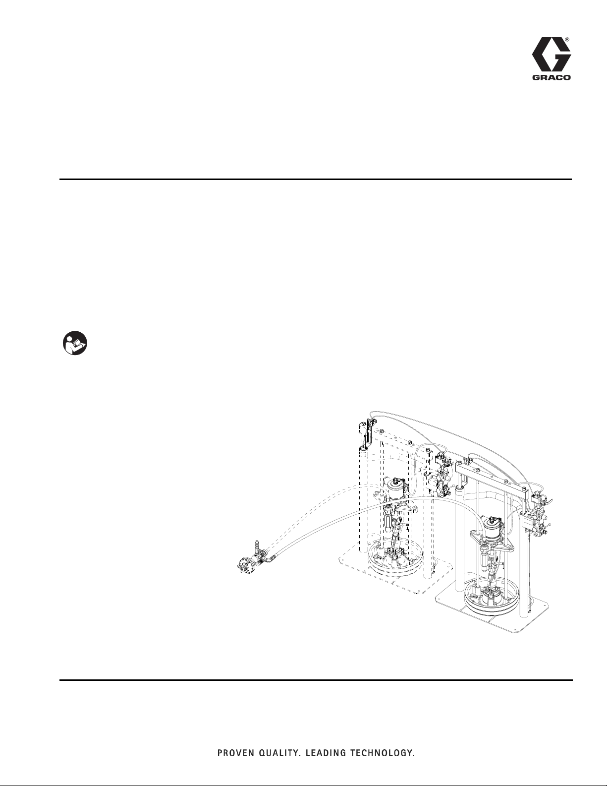
HFRS Tandem
3A2264A
Supply System Kit
For use with non-heated bulk supply of medium to high viscosity sealants and adhesive
materials. For professional use only.
Not approved for use in European explosive atmosphere locations.
EN
125 psi (0.9 MPa, 9 bar) Maximum Air Inlet Pressure - S20 3 in. rams
150 psi (1.0 MPa, 10 bar) Maximum Air Inlet Pressure - D200 3 in. rams
Important Safety Instructions
Read all warnings and instructions in manual
3A2175. Save all instructions.
24M226 Assembly Shown
r_24m226_cover
Page 2

Contents
Related Manuals . . . . . . . . . . . . . . . . . . . . . . . . . . . 3
Models . . . . . . . . . . . . . . . . . . . . . . . . . . . . . . . . . . . 4
Overview . . . . . . . . . . . . . . . . . . . . . . . . . . . . . . . . . . 5
Kit Description . . . . . . . . . . . . . . . . . . . . . . . . . . . 5
Pneumatic Crossover System Components . . . . 6
Integrated Air Controls . . . . . . . . . . . . . . . . . . . . 8
Air Line Accessories . . . . . . . . . . . . . . . . . . . . . . 8
Setup . . . . . . . . . . . . . . . . . . . . . . . . . . . . . . . . . . . . . 9
Ram Installation and Setup . . . . . . . . . . . . . . . . . 9
Grounding . . . . . . . . . . . . . . . . . . . . . . . . . . . . . 10
Pressure Relief Procedure . . . . . . . . . . . . . . . . . . 10
Startup . . . . . . . . . . . . . . . . . . . . . . . . . . . . . . . . . . 11
Shutdown . . . . . . . . . . . . . . . . . . . . . . . . . . . . . . . . 12
Prime . . . . . . . . . . . . . . . . . . . . . . . . . . . . . . . . . . . . 12
Troubleshooting . . . . . . . . . . . . . . . . . . . . . . . . . . . 13
Repair . . . . . . . . . . . . . . . . . . . . . . . . . . . . . . . . . . . 14
Ram Repair . . . . . . . . . . . . . . . . . . . . . . . . . . . . 14
Pump Repair . . . . . . . . . . . . . . . . . . . . . . . . . . . 14
Crossover Schematics . . . . . . . . . . . . . . . . . . . 14
Schematics . . . . . . . . . . . . . . . . . . . . . . . . . . . . . . . 15
Pneumatic Crossover . . . . . . . . . . . . . . . . . . . . 15
D200 Ram Tube Connection Diagram . . . . . . . 16
S20 Ram Tube Connection Diagram . . . . . . . . . 17
Parts . . . . . . . . . . . . . . . . . . . . . . . . . . . . . . . . . . . . 18
Tandem Supply System - D200 . . . . . . . . . . . . . 18
Tandem Supply System - S20 . . . . . . . . . . . . . . 20
Pneumatic Crossover Kits . . . . . . . . . . . . . . . . . 22
Pump Outlet Check Valve Kits . . . . . . . . . . . . . 25
Technical Data . . . . . . . . . . . . . . . . . . . . . . . . . . . . 26
Graco Standard Warranty . . . . . . . . . . . . . . . . . . . 28
Graco Information . . . . . . . . . . . . . . . . . . . . . . . . 28
2 3A2264A
Page 3

Related Manuals
Component Manuals in U.S. English:
Manual Description
313526 Supply Systems Operation
313527 Supply Systems Repair-Parts
312375
312376
312889
312374 Air Controls Instructions-Parts
Check-Mate
Instructions-Parts
Check-Mate
Instruction-Parts
60 cc Check-Mate Displacement Pump
Repair-Parts
®
Displacement Pumps
®
Pump Packages
Related Manuals
3A2264A 3
Page 4
Models
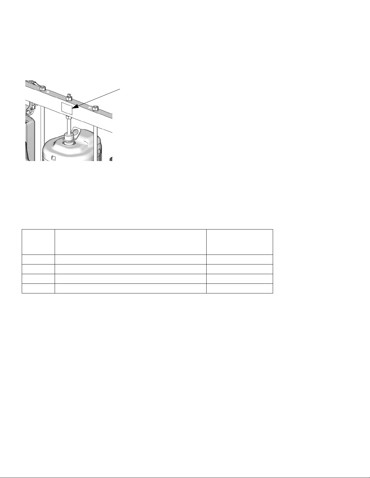
Models
Check the identification plate (ID) for the 6-digit part number of your tandem system.
ID
To order replacement parts, see Parts starting on page 18.
Each tandem supply kit consists of one single air-powered r
components necessary to configure all pneumatic tandem supply system controls. This kit must be added to an identical single ram supply system (identified with the model information) with supply hoses to make up a complete tandem supply unit. This kit is intended only f
manual 3A2175). Attempts to integrate with other systems may not be functional and may require additional parts.
Model Description
24M226 Tandem Crossover Kit, 20:1, 55 gallon, Carbon Steel CM7A59
24M227 Tandem Crossover Kit, 20:1, 55 gallon, Stainless Steel CM7C58
24M228 Tandem Crossover Kit, 20:1, 5 gallon, Carbon Steel CM7A3C
24M229 Tandem Crossover Kit, 20:1, 5 gallon, Stainless Steel CM7C3F
or use with HFRS systems that include a D200 or S20 supply system (See
am supply system and supply hose, as well as all the
o Be Installed with
T
Existing Supply
System
4 3A2264A
Page 5
Overview
Kit Description
Each tandem supply kit consists of one single air-powered ram supply system and supply hose, as well as all
he components necessary to configure all pneumatic
t
tandem supply system controls. This kit must be added
to an identical single ram supply system (identified with
the model information) with supply hoses to make up a
complete tandem supply unit. This kit is intended only
for use with HFRS systems that include a D200 or S20
supply system (See manual 3A2175). Attempts to integrate with other systems may not be functional and may
quire additional parts.
re
Keep clear of the inactive ram, as automatic crossover
may occur unexpectedly. To repair or adjust the ram, first
follow all steps of the Pressure Relief Procedure on
page 10.
Overview
3A2264A 5
Page 6

Overview
Pneumatic Crossover System Components
NOTE:
D200, and S20 sizes are used in pneumatic crossover systems.
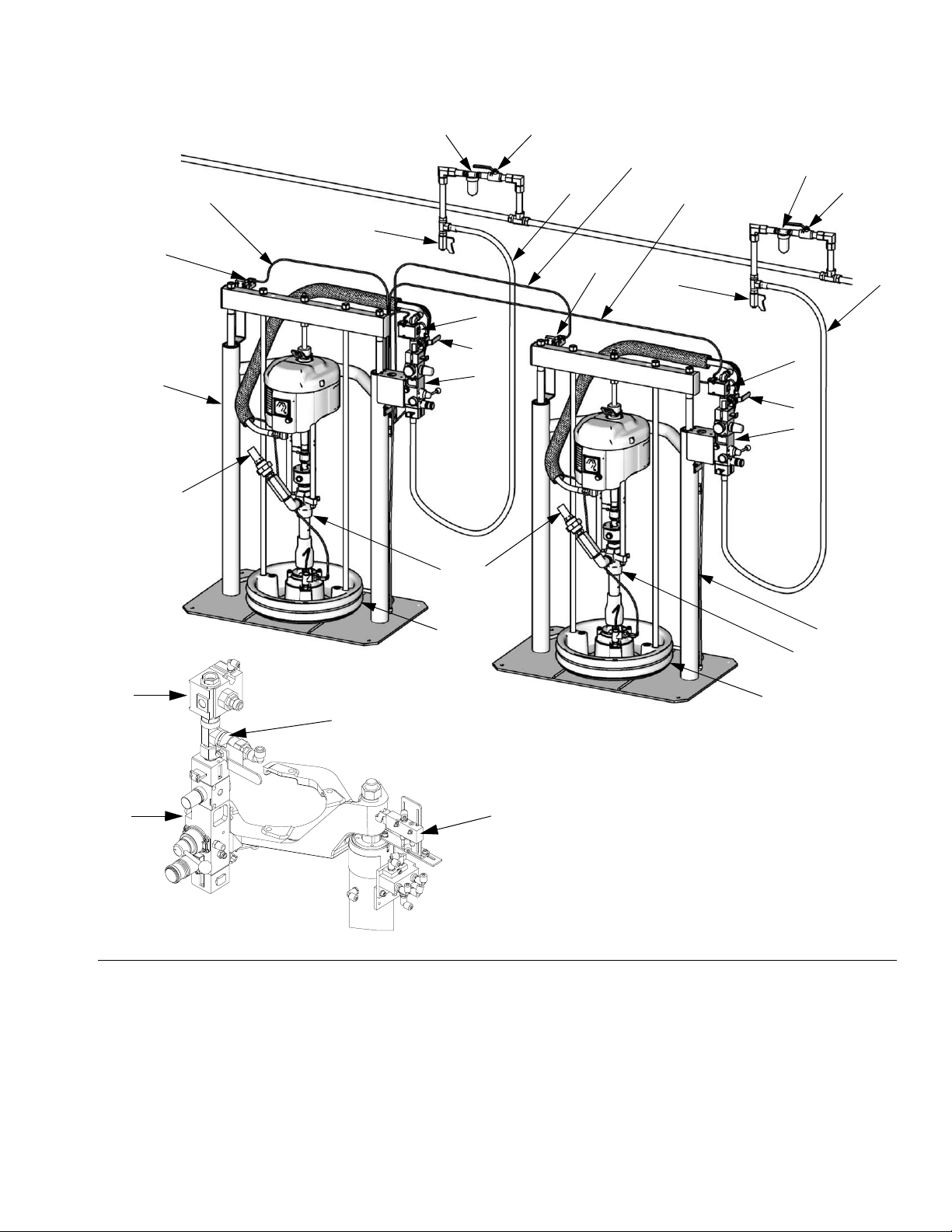
FIG. 1. shows a pneumatic crossover system. Refer to
manual 313526 (supplied) for ram installation and operating instructions. The pneumatic crossover operates as
follows:
During system operation, as the ram approaches the
drum bottom, the top of the ram contacts the limit switch
(E). The limit switch shuts off air to the air motor via a
solenoid valve (Y), which stops air flow to one motor and
starts air flow to the other air motor. This allows continu
ous material flow and changing of material drums.
The position of the limit switch (E) on the ram determines when the air motor is turned off. Start by positioning the limit switch to trip when the ram platen (D) is 1 in.
(25 mm) from the bottom of the drum. During operation
the position may be adjusted as desired.
The bypass valve (L) allows you to prime the inactive
pump after a drum change. Open the valve to prime the
pump. Close the valve when priming is complete, and
during normal operation.
-
6 3A2264A
Page 7
Overview
Typical Crossover System Diagram
AA
E
A
S
V
W
AB
T
AC
V
W
U
E
U
T
Y
L
Y
H
L
H
S
C
D
D200 Rams Shown
Y
L
H
S20 Ram Shown
FIG. 1: Component Identification, Pneumatic Crossover
Key to FIG. 1:
ARam A
BRam B
C Pump (Ram A and B)
D Platen (Ram A and B)
E Limit Switch (Ram A and B)
H Integrated Air Controls (Ram A and B); see page 8
L Bypass Valve (Ram A and B)
S Fluid Line (not supplied)
C
D
E
T Main Air Line (not supplied)
U Air Line Drain Valve (not supplied)
V Air Filter (not supplied)
W Bleed-Type Air Shutoff Valve (not supplied)
Y Solenoid Valve (Ram A and B)
AA Cable from Ram A to Limit Switch A
AB Cable from Ram A to Limit Switch B
AC Main Crossover Cable; from Ram A to Solenoid B
B
TI11160A
3A2264A 7
Page 8
Overview
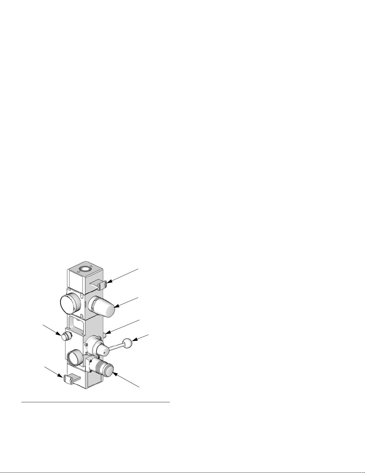
Integrated Air Controls
The integrated air controls include:
• Main air slider valve (BA): tu
the system. When closed, the valve relieves pressure downstream.
• Ram air regulator (BB): cont
pressure and blowoff pressure.
• Ram director
• Exhaust port with muffler (BD)
• Air motor regulator (BE): Cont
motor.
• Air m
otor slider valve (BF): turns air on and off to
the air motor. When closed, the valve relieves air
trapped between it and the air motor. Push the valve
in to shutoff. Remote DataTrak: The air solenoid
IG. 1), the air motor slider valve (BF), and the
(Y, F
main air slider valve (BA) must be open for air to
low. (See Remote DataTrak Setup section in Supply
f
Systems operation manual 313526.)
valve (BC): controls ram direction.
rns air on and off to
rols ram up and down
rols air pressure to
Air Line Accessories
See FIG. 1.
• Air line drain valve (U)
r line filter (V): removes harmful dirt and mois-
• Ai
ture from compress
• Sec
• Ai
ond bleed-type air valve (W): isolates air line
accessories and supply system for servicing. Locate
upstream from all other air line accessories.
r relief valve (attached to ram air regulator, not
visible): automatically relieves excessive pressure.
ed air supply.
• Blo
F
woff button (BG): turns air on and off to push
the platen out of an empty drum.
BG
BA
IG. 2. Integrated Air Controls
TI10438A
BF
BE
BD
BC
BB
8 3A2264A
Page 9

Setup
Setup
Ram Installation and Setup
1. Install and set up individual rams as explained in
manual provided.
2. Install outlet check valve assemblies on each ram.
Refer to page 25.
3. Install pneumatic crossover kits components on
each ram.
a. See pilot valve assembly drawing on page 22.
b. Identify and locate the integrated air control
module.
c. Remove the air hose and air fitting from the top
of the integrated air control module.
NOTE: Leave the hose attached to the air motor on the
other end
d. Install the pilot valve assembly on top of the
integrated air control module as shown on page
22.
k. Tube the system using the appropriate D200 or
S20 tubing drawing.
NOTE: The table on the drawing shows tubing cut
lengths. Using longer tube lengths will require additional
tubing (not provided).
4. When tubing is complete, slowly extend rams to the
full up and full down positions and take note how the
tubing moves.
5. Secure tubing in place with tape or wire ties.
NOTICE
To avoid machine damage and ensure proper operation, verify tubes are not pinched, kinked, or pulled
taught where they are secured when the rams are
raised or lowered.
e. Install removed fitting from step c into port 1 of
the pilot valve assembly.
f. Remove plug located on the integrated air con-
trol moduel and replace it with a tube fitting.
(See item 209 on page 22).
g. Install the crossover valve assembly on the ram
cylinder as shown on page 22. This assembly
will be installed on only one ram.
h. See tubing drawing on page 16 (D200 Ram
Tube Connection Diagram) or page 17 (S20
Ram Tube Connection Diagram) for location
of level switch assembly.
i. Install level switch assembly to the top of the
ram cylinder as shown on page 23.
j. Calibrate the switch to trip when the follower is
about 2 in (51 mm) above the ram base.
3A2264A 9
Page 10

Pressure Relief Procedure
Grounding
The equipment must be grounded. Grounding reduces
the risk of static and electric shock by providing an
escape wire for the electrical current due to static build
up or in the event of a short circuit.
Pump: use g
grounding lug locknut and washer. Insert ground wire
end into lug slot and tighten locknut securely. Connect
ground clamp to a true earth ground.
Air and fluid hoses: use on
hoses with a maximum of 500 ft. (150 m) combined
hose length to ensure grounding continuity. Check electrical resistance of hoses. If to
exceeds 29 megohms, replace hose immediately.
Air compressor:
tions.
round wire and clamp (supplied). Loosen
ly electrically conductive
tal resistance to ground
follow manufacturer’s recommenda-
Pressure Relief
Procedure
NOTE: Refer to FIG. 2 on page 8 for the following proce-
dure.
1. Turn off the air motor slider valve (BF) on both ram A
d B.
an
2. On both ram A and B, turn off the main air slider
valve (BA). Set the ram director valve (BC) to the
down position. The ram will slowly drop.
3. Perform Pressure Relief Procedure of the HFR
system. See manual 3A2175.
4. On both ram A and B, open the drain valve and/or
the pump bleed port. Have a container ready to
catch the drainage.
Dispense valve: g
erly grounded fluid hose and pump.
Fluid supply container: f
Solvent pails used when flushing: f
Use only conductive metal pails, placed on a grounded
surface. Do not place the pail on a nonconductive surface, such as paper or cardboard, which interrupts
rounding continuity.
g
To maintain grounding continuity when flushing or
lieving pressure: hold metal part of the dispense
re
valve firmly to the side of a grounded metal pail, then
trigger the valve.
round through connection to a prop-
ollow local code.
ollow local code.
If you suspect that the spray tip/nozzle or hose is completely clogged, or that pressure has not been fully
ved after following the steps above, very slowly
relie
loosen the tip guard retaining nut or hose end coupling
and relieve pressure gradually, then loosen completely.
Now clear the tip/nozzle or hose.
10 3A2264A
Page 11

Startup
Startup
Flush Before Using Equipment
The pump was tested with lightweight oil, which is left in
the fluid passages to protect parts. To avoid contaminating your fluid with oil, flush the pump with a compatible
ent before use. See your pump manual for flushing
solv
directions.
1. Perform Setup on pa
2. Verify the following:
• That you have equal line air pressure supplied
o both A & B units within 5 psi (35 kPa, 0.3 bar)
t
of each other.
• The Bypass/Prime ball valves (item L in F
page 7) are closed,
• That the air motor regulators are adjusted to
30 psi (210 kPa, 2.1 bar)
To prevent pump seal damage, adjust the pressure
wn if the motor cycles too rapidly during the follow-
do
ing test procedure
ge 9.
IG. 1,
NOTICE
10. Move to the current “Active” ram and lower it to the
bottom.
11. Verify that the cross bar contacts and actuates the
Air Limit Valve when lowered and that the Ram
Crossover occurs.
NOTE: Th
become “Inactive” and the opposite ram motor should
begin to cycle becoming “Active”).
12. Verify that the Bypass/Prime function works on the
13. Close Bypass/Prime ball valve.
14. Lower the “Active” ram to the bottom. Verify that
NOTE: Wh
ram is still lowered, a crossover should not occur. A
crossover in this condition could be caused by an air
leak, unequal supply line pressures, or a problem with
the 4-way Remote Air Valve.
15. Raise the opposit ram.
e motor of the ram lowered should stop and
nactive” ram by opening the Bypass/Prime ball
“I
valve. The “Inactive” ram motor should begin to
cycle (the “Active” ram should continue to cycle).
Ram Crossover does not occur.
en an Active ram is lowered while the Inactive
3. Position both A & B units about half way up, place in
“N
eutral”, and open both motor isolation slider
valves (item BA in F
4. Verify that only one ram unit motor cycles.
5. Go to the “Active” ram with the cycling motor and
lower it to the bottom.
6. Verify that the cross bar contacts and actuates the
Air Limit Valve when lowered and that the Ram
Crossover occurs.
NOTE: T
become “Inactive” and the opposite ram motor should
begin to cycle becoming “Active”).
7. Verify that the Bypass/Prime function works on the
8. Close the Bypass/Prime ball valve.
9. Raise the “Inactive” ram about half way and place in
he motor of the ram lowered should stop and
nactive” ram by opening the Bypass/Prime ball
“I
valve. The “Inactive” ram motor should begin to
cycle (the “Active” ram should continue to cycle).
“Neutral”.
IG. 2 on page 8).
. Verify that crossover occurs when the Air Limit Valve
16
is deactivated. Lower the same ram and verify that
Ram Crossover does NOT occur.
17. Startup Complete.
3A2264A 11
Page 12

Shutdown
Shutdown
Turning the system OFF relieves pressure from the
pump motor. It does not depressurize the fluid pressure. Follow the Pressure Relief Procedure, page
10.
The tandem supply controls do not effect essential system operation.
The tandem controls act to allow only one of the two
mp air motors to run at any given time, unless the
pu
pilot valve is bypassed. To manually activate the air
motor, open the bypass ball valve (F
system functions are not effected by the tandem controls.
1. Follow the procedure defined in the supply system
nual for shutdown.
ma
IG. 1, item L). Other
Prime
If the pump being primed is not the active pump, it will
be necessary to activate the air motor by opening the
bypass ball valve (F
1. Follow the procedure defined in the supply system
nual for priming.
ma
2. After priming, close the bypass ball valve to allow
the level sensors to shutdown the air motor.
IG. 1, item L).
12 3A2264A
Page 13

Troubleshooting
Troubleshooting
NOTE: Refer to the Supply System Repair-Parts
manual for specific ram troubleshooting. Refer to
the Check-Mate Pump Packages manual for pump
troubleshooting.
Problem Cause Verification Solution
Does not crossover. Alternate ram has an empty
sensor activated.
Alternate pump is not
primed.
Level switch not adjusted to
trip properly.
1. Follow Pre
disassembling any part of the supply system.
2. Disconnect power before repairing the supply system.
3. Check all possible problems and causes before disassembling the supply system.
Verify ram has material. Replace empty drum.
Verify alternate ram is
ready to run.
Verify level switches activate at desired low level
point.
ssure Relief Procedure, page 10, before
Prime pump.
Adjust level switch.
3A2264A 13
Page 14

Repair
Repair
Ram Repair
See manual 313527 for ram and platen repair procedures and replacement parts.
Pump Repair
See pump manuals for pump repair procedures and
replacement parts.
See manual 312796 for air motor repair procedures and
replacement parts.
Crossover Schematics
See page 15 for a schematic of pneumatic crossover
systems.
14 3A2264A
Page 15

Schematics
Pneumatic Crossover
P1
LEVEL
RAM B
SWITCH
V2
2
315
Schematics
4
A2
LEVEL
RAM A
SWITCH
A2
RAM B
V1
3(CYL)
PILOT
REMOTE
1(IN)
PILOT
VALV E
2
P2
315
C2C1
2(EX)
VALV E
RAM B
BYPASS
V2
INTEGRATED
AIR CONTROL
4
ESTCODE
PUMP
RAM B
RAM B
AIR
V2
INLET
A1
RAM A
3(CYL)
PILOT
REMOTE
1(IN)
2(EX)
PILOT
VALV E
VALV E
RAM A
BYPASS
INTEGRATED
AIR CONTROL
M1
ESTCODE
PUMP
RAM A
RAM A
AIR
P1
INLET
A
A1
B
A
A2
B
P2
IN
EX
V1
M1
TEE
V1
3A2264A 15
Page 16

Schematics
D200 Ram Tube Connection Diagram
C1
M1
A2
P1
A1C1
V1 P2 C2 C2 P1
V2
A1
P2
V1
A2
V2
M1
Tube Size
Tag
A1 1/4 36 (914) Pilot air to switch on Unit A air motor
A2 1/4 180 (4572) Pilot air to switch on Unit B air motor
C1 3/8 6.5 (165) Bypass air - Unit A
C2 3/8 6.5 (165) Bypass air - Unit B
M1 1/4 20 (508) Main air to 4-way valve
P1 1/4 180 (4572) Pilot air to switch from Unit B to A
P2 1/4 68 (1727) Pilot air to switch from Unit A to B
V1 1/4 68 (1727) Supply air to limit valve - Unit A
V2 1/4 68 (1727) Supply air to limit valve - Unit B
16 3A2264A
(in.)
Length
in (mm) Function
Page 17

S20 Ram Tube Connection Diagram
Schematics
C1
C1
M1
A1
P2
V1
P1
A2
A1
M1
P2
V1
C2
C2
A2
P1
V2
V2
Tube Size
Tag
A1 1/4 61 (1550) Pilot air to switch on Unit A air motor
A2 1/4 180 (4572) Pilot air to switch on Unit B air motor
C1 3/8 6.5 (165) Bypass air - Unit A
C2 3/8 6.5 (165) Bypass air - Unit B
M1 1/4 49 (1245) Main air to 4-way valve
P1 1/4 180 (4572) Pilot air to switch from Unit B to A
P2 1/4 7 (178) Pilot air to switch from Unit A to B
V1 1/4 12 (305) Supply air to limit valve - Unit A
V2 1/4 49 (1245) Supply air to limit valve - Unit B
3A2264A 17
(in.)
Length
in (mm) Function
Page 18

Parts
Parts
Tandem Supply System - D200
003
Supply System A
005,
006
004
002
003
003
Supply System B
003
005,
006
002
007
001
009 (2x)
008 (2x)
006
18 3A2264A
Page 19

Quantity
Ref Part Description
24M226, KIT,
upgrade, 20:1,
pxover, 55 gallon,
carbon
24M227, KIT,
upgrade, 20:1,
pxover, 55 gallon,
stainless
001 CM7A59 SUPPLY UNIT, 20:1, 0 volt, d200 1
CM7C58 SUPPLY UNIT, 20:1, 0 volt, d200 1
002 257377 KIT, pump outlet check 2
255452 KIT, pump outlet, check, carbon steel 2
003 255675 KIT, pneumatic cross-over 1 1
004 24F726 HOSE, assy, 3/4id, female/male, sst 1
24M225 HOSE, coupled, 180l, 3/4id 1
005 C19661 BUSHING, reducing 2
006 124406 FITTING, adapter, 3/4npt x 12jic 3
15M863 FITTING, connector, male 1
007 801787 FITTING, tee, pipe 3\4 1
113833 TEE, pipe, female 1
008 122763 FITTING, elbow, straight, 3/4npt, 90, ss 2
122327 FITTING, elbow, street 2
009 6303-21 ADAPTER, swvl, jic12x3/4npt, feamle/male 2
124433 FITTING, swivel, 3/4nptx12jic, male/female, sst 2
Parts
3A2264A 19
Page 20

Parts
Tandem Supply System - S20
004
005,
006
002
Supply System A
007
003
Supply System B
003
005,
006
002
001
009 (2x)
008 (2x)
006
20 3A2264A
Page 21

Quantity
Parts
Ref Part Description
24M228, KIT,
upgrade, 20:1,
pxover, 5 gallon,
carbon
24M229, KIT,
upgrade, 20:1,
pxover, 5 gallon,
stainless
001 CM7A3C SUPPLY UNIT, 20:1, 0 volt, s20, 20l 1
CM7C3F SUPPLY UNIT, 20:1, 0 volt, s20, 20l 1
002 257377 KIT, pump outlet check 2
255452 KIT, pump outlet, check, carbon steel 2
003 257373 KIT, pneumatic xover 1 1
004 24F726 HOSE, assy, 3/4id, 180l, feamle/male, sst 1
24M225 HOSE, cpld, 180l, 3/4id 1
005 C19661 BUSHING, reducing 2
006 124406 FITTING, adapter, 3/4npt x 12jic 3
15M863 FITTING, connector, male 1
007 801787 FITTING, tee, pipe 3\4 1
113833 TEE, pipe, female 1
008 122763 FITTING, elbow, straight, 3/4npt, 90 2
122327 FITTING, elbow, street 2
009 6303-21 ADAPTER, swivel, jic12x3/4npt, female/male 2
124433 FITTING, swivel, 3/4nptx12jic, male/female 2
3A2264A 21
Page 22

Parts
Pneumatic Crossover Kits
255675, for 3 in. D200 Rams
257373 for S20 Rams
Pilot Valve Assembly 255675
229
202
201
203
206
207
205
204
206
208
209
Pilot Valve Assembly 257373
207
206
229
235
206
203
202
201
233
205
208
204
209
223
221
TI10932A
Typical Crossover Valve
Assembly
222
230
226
229 229
r_257373_313529_2a
229
224
214
225
229
225
TI10941A
22 3A2264A
Page 23

Pneumatic Crossover Kits (continued)
Level Switch Assembly 255675
Parts
218
217
228
216
226
229
226
211
215 214
210
216
219
229
220
228
213
212
214
215
222
221
TI10942A
Level Switch Assembly 257373
229
211
222
213
218
219
217
220
226
229
3A2264A 23
212
221
226
210
214
215
r_257373_313529_1a
Page 24

Parts
Pneumatic Crossover Kits
Ref. Part Description Qty
201 111337 TEE, street; 3/4 npt(m) x 3/4 npt(f) x 3/4 npt(f) 2
202 C20487 NIPPLE, hex; 3/4 npt 2
203 C59752 VALVE, pneumatic, 3-way. 2
204 113218 VALVE, ball, vented; 3/4 npt (m x f) 2
205 C12508 HOSE, nylon; 3/8 in. (10 mm) OD; 6 in. (153 mm);
black
206 C19683 BUSHING, reducing; 3/4 npt(m) x 3/8 npt(f) 4
207 115240 FITTING, tube; 3/8 npt(m) x 3/8 in. (10 mm) OD tube 2
208 115436 ELBOW, tube, 90°; 3/8 npt(m) x 3/8 in. (10 mm) OD
tube
209 116658 FITTING, tube; 1/4 npt(m) x 1/4 in. (6 mm) OD tube 2
210 --- BRACKET, crossover 2
211 --- BRACKET, limit valve; for D200 rams 2
--- BRACKET, limit valve; for S20 rams 2
212 104116 WASHER, plain; #10 4
213 111820 SCREW, cap, socket hd; 10-24 x 3/4 in. (19 mm) 4
214 C19204 WASHER, lock; #10 6
215 100179 NUT, hex mscr; 10-24 4
216 C06182 VALVE, limit, air 2
217 100813 WASHER, flat 4
218 C19965 SCREW, cap, socket-hd; 6-32 x 1-1/4 in. (31 mm) 4
219 100068 WASHER, lock, spring; #6 4
220 100072 NUT, hex mscr; 6-32 4
221 100016 WASHER, lock; 1/4 6
222 101682 SCREW, cap, socket-hd; 1/4-20 x 5/8 in. (16 mm) 6
223 --- PLATE, mounting, 4-way valve 1
224 113338 VALVE, air, remote, 4-way 1
225 123366 SCREW, cap, socket-hd; 10-24 x 1-1/8 in. (29 mm) 2
226 C06061 MUFFLER 5
228 100139 PLUG, pipe; 1/8 npt 2
229 597151 ELBOW, tube; 1/8 npt(m) x 1/4 in. OD tube 12
230 110475 TEE, street; 1/8 npt(m) x 1/8 npt(f) x 1/8 npt(f) 1
231 C12509 TUBE, nylon; 1/4 in. (6 mm) OD; 52 ft (15.9 m); black AR
232★ 114958 STRAP, tie 4
233 104969 BUSHING, reducing; for S20 rams 2
235 100896 BUSING, reducing 2
AR
2
★ Not shown.
--- Not for sale.
24 3A2264A
Page 25

Pump Outlet Check Valve Kits
255452, used on carbon steel Check-Mate 60 and 100 Displacement Pumps (shown)
257377, used on stainless steel Check-Mate 60 and 100 Displacement Pumps
5
Ref. Description 255452 257377
401 UNION, pipe; 1-1/4 in. npt(f) 521975
CONNECTOR; 3/4 npt(m) x 1
in. unf
402 NIPPLE, hex; 1-1/4 in. npt C20490
NIPPLE, hex; 1-1/4 in. npt
NIPPLE, reducing; 1 in. npt x
3/4 npt
403 VALVE, check; 1-1/4 in. npt
(fbe)
VALVE, check; 3/4 npt (fbe) C59546
404 ELBOW, street, 90°; 1 in. npt (m
x f)
ELBOW; 3/4 npt (m x f) 15M864
521850
C38324
15M863
Ref. Description 255452 257377
ELBOW; 1-1/2 in. npt (f x f)
405 BUSHING, reducing; 1 in.
npt(m) x 3/4 npt(f)
NIPPLE, reducing; 1-1/4 in. npt
x 1 in. npt
NIPPLE, reducing; 1 in. npt x
3/4 npt
BUSHING, reducing; 1-1/2 npt
x 1-1/4 npt (fbe)
COUPLING, reducing; 1-1/2 in.
npt x 1 in. npt (fbe)
Parts
C19661
4.
401
402
403
404
405
TI10888A
255455 Shown
401
402
403
402
405
404
r_255455_313529_1f
3A2264A 25
Page 26

Technical Data
Technical Data
Max air input pressure (supply system) psi (MPa, bar) / Air inlet size
S20 - 3 in. single post, 5 gal. (20 L) . . . . . . . . . . . . . . 125 (0.9, 9) / 1/2 npt(f)
D200 - 3 in. dual post, 55 gal. (200 L), 30 gal. (115 L),
16 gal. (60 L), 8 gal. (30 L), 5 gal. (20 L). . . . . . . . . . 150 (1.0, 10) / 3/4 npt(f)
Max fluid, air working pressure, and weigh
(displacement pump) . . . . . . . . . . . . . . . . . . . . . . . . . For Check-Mate pump packages, see manual 312376.
Pump Wetted parts . . . . . . . . . . . . . . . . . . . . . . . . . . . . . For Check-Mate displacement pumps, see manual
312375.
Ambient operating temperature range (supply system) 32-120 °F (0- 49°C)
Sound data. . . . . . . . . . . . . . . . . . . . . . . . . . . . . . . . . . . . See separate air motor manual.
26 3A2264A
Page 27

Technical Data
3A2264A 27
Page 28

Graco Standard Warranty
Graco warrants all equipment referenced in this document which is manufactured by Graco and bearing its name to be free from defects in
material and workmanship on the date of sale to the original purchaser for use. With the exception of any special, extended, or limited warranty
published by Graco, Graco will, for a period of twelve months from the date of sale, repair or replace any part of the equipment determined by
Graco to be defective. This warranty applies only when the equipment is installed, operated and maintained in accordance with Graco’s written
recommendations.
This warranty does not cover, and Graco shall not be liable for general wear and tear, or any malfunction, damage or wear caused by faulty
installation, misapplication, abrasion, corrosion, inadequate or improper maintenance, negligence, accident, tampering, or substitution of
non-Graco component parts. Nor shall Graco be liable for malfunction, damage or wear caused by the incompatibility of Graco equipment with
structures, accessories, equipment or materials not supplied by Graco, or the improper design, manufacture, installation, operation or
maintenance of structures, accessories, equipment or materials not supplied by Graco.
This warranty is conditioned upon the prepaid return of the equipment claimed to be defective to an authorized Graco distributor for verification of
the claimed defect. If the claimed defect is verified, Graco will repair or replace free of charge any defective par ts. The equipment will be returned
to the original purchaser transportation prepaid. If inspection of the equipment does not disclose any defect in material or workmanship, repairs will
be made at a reasonable charge, which charges may include the costs of parts, labor, and transportation.
THIS WARRANTY IS EXCLUSIVE, AND IS IN LIEU OF ANY OTHER WARRANTIES, EXPRESS OR IMPLIED, INCLUDING BUT NOT LIMITED
TO WARRANTY OF MERCHANTABILITY OR WARRANTY OF FITNESS FOR A PARTICULAR PURPOSE.
Graco’s sole obligation and buyer’s sole remedy for any breach of warranty shall be as set forth above. The buyer agrees that no other remedy
(including, but not limited to, incidental or consequential damages for lost profits, lost sales, injury to person or property, or any other incidental or
consequential loss) shall be available. Any action for breach of warranty must be brought within two (2) years of the date of sale.
GRACO MAKES NO WARRANTY, AND DISCLAIMS ALL IMPLIED WARRANTIES OF MERCHANTABILITY AND FITNESS FOR A
PARTICULAR PURPOSE, IN CONNECTION WITH ACCESSORIES, EQUIPMENT, MATERIALS OR COMPONENTS SOLD BUT NOT
MANUFACTURED BY GRACO. These items sold, but not manufactured by Graco (such as electric motors, switches, hose, etc.), are subject to
the warranty, if any, of their manufacturer. Graco will provide purchaser with reasonable assistance in making any claim for breach of these
warranties.
In no event will Graco be liable for indirect, incidental, special or consequential damages resulting from Graco supplying equipment hereunder, or
the furnishing, performance, or use of any products or other goods sold hereto, whether due to a breach of contract, breach of warranty, the
negligence of Graco, or otherwise.
FOR GRACO CANADA CUSTOMERS
The Parties acknowledge that they have required that the present document, as well as all documents, notices and legal proceedings entered into,
given or instituted pursuant hereto or relating directly or indirectly hereto, be drawn up in English. Les parties reconnaissent avoir convenu que la
rédaction du présente document sera en Anglais, ainsi que tous documents, avis et procédures judiciaires exécutés, donnés ou intentés, à la suite
de ou en rapport, directement ou indirectement, avec les procédures concernées.
Graco Information
For the latest information about Graco products, visit www.graco.com.
TO PLACE AN ORDER, contact your Graco distributor or call to identify the nearest distributor.
Toll Free: 1-800-746-1334 or Fax: 330-966-3006
All written and visual data contained in this document reflects the latest product information available at the time of publication.
GRACO INC. AND SUBSIDIARIES • P.O. BOX 1441 • MINNEAPOLIS MN 55440-1441 • USA
Copyright 2011, Graco Inc. All Graco manufacturing locations are registered to ISO 9001.
Graco reserves the right to make changes at any time without notice.
Original instructions. This manual contains English. MM 3A2264
Graco Headquarters: Minneapolis
International Offices: Belgium, China, Japan, Korea
www.graco.com
 Loading...