

Page 1
Repair - Parts
3A2176J
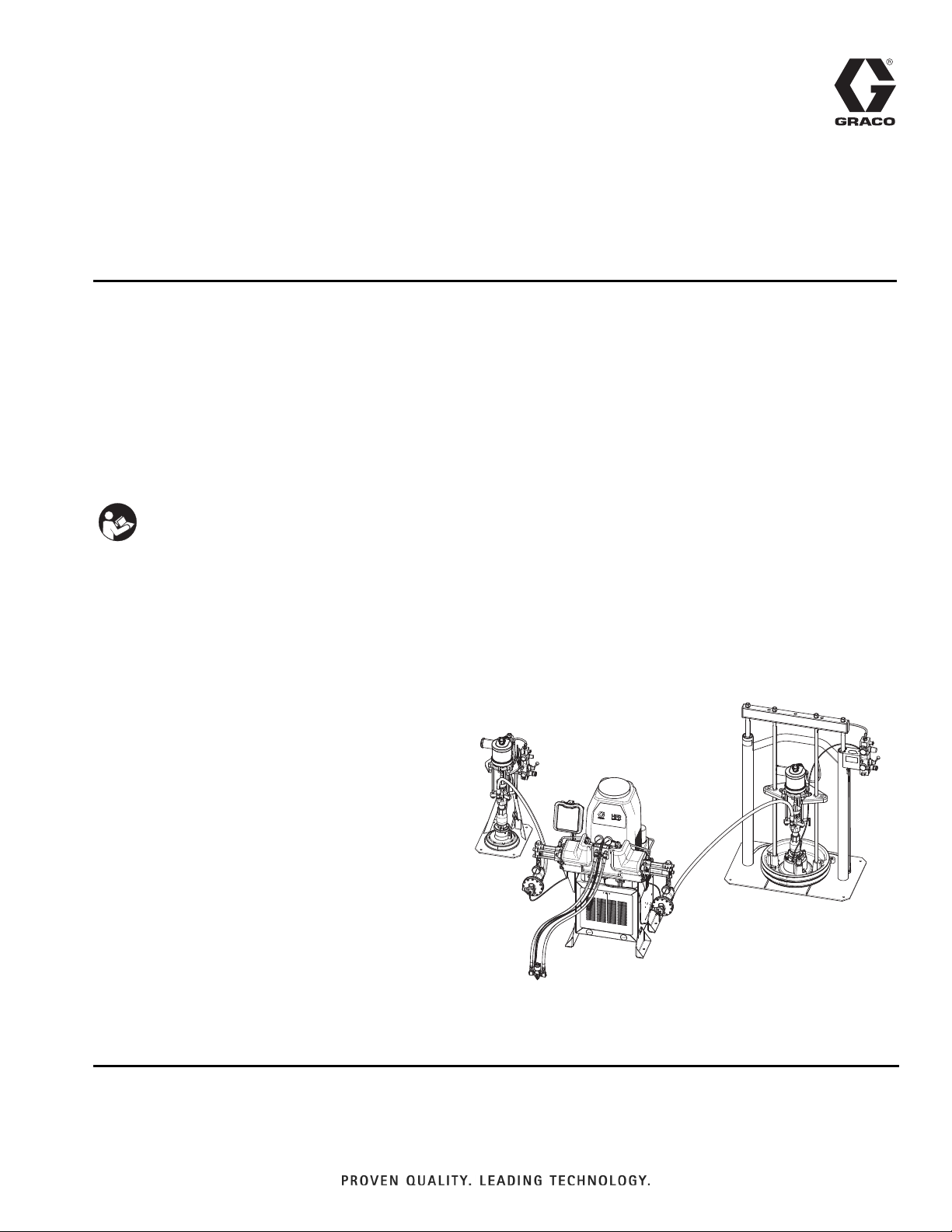
HFRL and HFRS
Hydraulic, Plural-Component, Fixed-Ratio Proportioner.
For pouring and dispensing laminates and silicones.
For professional use only. Not approved for use in explosive atmospheres or hazardous
locations.
Important Safety Instructions
Read all warnings and instructions in this
manual. Save these instructions.
EN
See page 4 for model information and maximum
working pressure.
ti18208a
Silicone unit shown.
Page 2

Contents
Related Manuals ...........................3
Models ...................................4
HFR-Laminate (HFRL) ....................4
HFR-Silicone (HFRS) .....................6
Warnings ................................10
Important Two-Component Material Information 14
Isocyanate Conditions .................... 14
Material Self-ignition .....................14
Keep Components A (Red) and B (Blue) Separate
14
Moisture Sensitivity of Isocyanates ..........14
Changing Materials ......................15
A (Red) and B (Blue) Components ............ 15
Operation ................................16
Shutdown .............................16
Pressure Relief Procedure ................16
Flushing .............................. 17
Repair ...................................18
Pumpline ..............................18
Hydraulic Power Pack Repair ..............25
Replace Power Supply ...................31
Replace Circuit Breaker ..................31
Parts ....................................32
HFRL Models .......................... 32
HFRS Models ..........................34
Base Module ........................... 40
Power Pack Module ...................... 44
Hydraulic DC Power Pack Module, 257442 .... 46
Power Modules, 24M034 & 24M035 ......... 48
Power Panels, 24M030 & 24M031 .......... 50
Fluid Outlet Modules, 24M167 & 24M168 ..... 52
Fluid Manifolds, 255629 & 289999 ..........54
Fluid Inlet Assembly, 24M129 (HFRL) ........56
Fluid Inlet Assemblies, 24M132 & 24M133 (HFRS)
58
Dispense Hose Assembly Kits ............. 60
Inlet Hose Assembly Kits ................. 62
Lubrication Kit, 24M154 .................. 63
Logic Drawings ...........................64
230V, 1 Phase .........................64
400V, 3 Phase ..........................65
DC Hydraulic Power Pack ................. 66
Motor Control Module (MCM) .............. 67
Accessories ..............................69
Technical Data ............................ 70
Motor Control Module Technical Data ........71
Graco Standard Warranty ...................72
Graco Information .........................72
2 3A2176J
Page 3

Related Manuals
Manuals are available at www.graco.com.
Component manuals in U.S. English:
System Manuals
3A2175 HFRL and HFRS Setup-Operation
Pumpline Manuals
3A0019 Z-Series Chemical Pumps Instructions-Parts
3A0020
Feed System Manuals
3A0235 Feed Supply Kits Instructions-Parts
Dispense Valve Manuals
312185 MD2 Valve, Instructions-Parts
Accessory Manuals
HFR™Hydraulic Actuator Instructions-Parts
Related Manuals
3A1149 HFR Discrete Gateway Module Kits Manual
3A2176J 3
Page 4

Models
Models
HFR-Laminate (HFRL)
HFRL models are designed for use with low viscosity, unheated urethane laminating adhesives at flow rates of up to
30 cc/sec (4 lb/min) @ 1500 psi (10 MPa, 103 bar).
A Pump
Size
160 86 246 8
100 86 186 10 1.16
86 80 166 11 1.08
80 80 160 12 1.00
80 65 145 13 1.23
80 60 140 13 1.33
80 50 130 14 1.60
86 40 126 15 2.15
60 50 110 17 1.20
65 40 105 18 1.63
60 40 100 19 1.50
60 25 85 20 28 (3.7) 2.40
50 30 80 20 26 (3.5) 1.67
50 25 75 20 25 (3.3) 2.00
50 20 70 20 23 (3.1) 2.50
** Cycle rate should be between 8 and 20 cycles per minute. Max flow rate is determined for continuous service at
120°F (39°C) at stated cpm and pressure. Higher cycle rates are possible at lower temperatures/pressures and
intermittent use. Lower cycle rates may be possible, but should be tested under application conditions.
B Pump
Size cc/cycle
Required cpm@
Flow**
Max Flow †
cc/sec (lb/min) @ 1500 psi (10 MPa, 103 bar) Ratio
1.86
30 (4)
† Dispense rate in excess of max flow and pressure may result in an elevated temperature of the hydraulic system,
resulting in a thermal shutdown (T4H1). Other system models are available for sustained flow rates and pressures
in excess of above.
4 3A2176J
Page 5
Models
HFRL Models
Part Number Description
HFRL01 HFR for Lamination, 230/1, 1.00:1,
80/80, Carbon Steel
HFRL02 HFR for Lamination, 230/1, 1.08:1,
86/80, Carbon Steel
HFRL03 HFR for Lamination, 230/1, 1.16:1,
100/86, Carbon Steel
HFRL04 HFR for Lamination, 230/1, 1.20:1,
60/50, Carbon Steel
HFRL05 HFR for Lamination, 230/1, 1.23:1,
80/65, Carbon Steel
HFRL06 HFR for Lamination, 230/1, 1.33:1,
80/60, Carbon Steel
HFRL07 HFR for Lamination, 230/1, 1.50:1,
60/40, Carbon Steel
HFRL08 HFR for Lamination, 230/1, 1.60:1,
80/50, Carbon Steel
HFRL09 HFR for Lamination, 230/1, 1.63:1,
65/40, Carbon Steel
HFRL10 HFR for Lamination, 230/1, 1.67:1,
50/30, Carbon Steel
HFRL11 HFR for Lamination, 230/1, 1.86:1,
160/86, Carbon Steel
HFRL12 HFR for Lamination, 230/1, 2.00:1,
50/25, Carbon Steel
HFRL13 HFR for Lamination, 230/1, 2.15:1,
86/40, Carbon Steel
HFRL14 HFR for Lamination, 230/1, 2.40:1,
60/25, Carbon Steel
HFRL15 HFR for Lamination, 230/1, 2.5:1,
50/20, Carbon Steel
HFRL16
★✖
HFRL17
★✖
HFRL18
★✖
HFRL19
★✖
HFRL20
★✖
HFRL21
★✖
HFRL22
★✖
HFR for Lamination, 400/3, 1.00:1,
80/80, Carbon Steel
HFR for Lamination, 400/3, 1.08:1,
86/80, Carbon Steel
HFR for Lamination, 400/3, 1.16:1,
100/86, Carbon Steel
HFR for Lamination, 400/3, 1.20:1,
60/50, Carbon Steel
HFR for Lamination, 400/3, 1.23:1,
80/65, Carbon Steel
HFR for Lamination, 400/3, 1.33:1,
80/60, Carbon Steel
HFR for Lamination, 400/3, 1.50:1,
60/40, Carbon Steel
Part Number
HFRL23
★✖
HFRL24
★✖
HFRL25
★✖
HFRL26
★✖
HFRL27
★✖
HFRL28
★✖
HFRL29
★✖
HFRL30
★✖
★ approved.
✖ See 400 V Power Requirements.
Description
HFR for Lamination, 400/3, 1.60:1,
80/50, Carbon Steel
HFR for Lamination, 400/3, 1.63:1,
65/40, Carbon Steel
HFR for Lamination, 400/3, 1.67:1,
50/30, Carbon Steel
HFR for Lamination, 400/3, 1.86:1,
160/86, Carbon Steel
HFR for Lamination, 400/3, 2.00:1,
50/25, Carbon Steel
HFR for Lamination, 400/3, 2.15:1,
86/40, Carbon Steel
HFR for Lamination, 400/3, 2.40:1,
60/25, Carbon Steel
HFR for Lamination, 400/3, 2.5:1,
50/20, Carbon Steel
400 V Power Requirements
• 400 V systems are intended for International voltage
requirements. Not for voltage requirements in North
America.
• If a 400 volt configuration is operated in North America, a special transformer rated for 400 V (“Y” configuration (4 wire)) may be required.
• North America mostly employs a 3 wire or Delta
configuration. The two configurations are not interchangeable.
3A2176J 5
Page 6

Models
HFR-Silicone (HFRS)
HFRS models are designed for use with high viscosity, unheated silicone adhesives at flow rates of up to
20 cc/sec (3 lb/min) @ 2500 psi (17 MPa, 172 bar). The equipment can be run at up to 20 cycles per minute
continuous duty.
A Pump
Size
10 100 110 11 5.6 20 10.00
15 80 95 12.5 4.8 20 5.33
40 40 80 15 4 20 1.00
10 60 70 17 3.6 20 6.00
20 40 60 20 3 20 2.00
10 40 50 20 2.5 16.7 4.00
10 10 20 12 1 4 1.00
** Cycle rate should be between 3 and 20 cycles per minute. Max flow rate is determined for continuous service at
120°F (39°C) at stated cpm and pressure. Higher cycle rates are possible at lower temperatures/pressures and
intermittent use. Lower cycle rates may be possible, but should be tested under application conditions.
† Flow rates are established @ 2500 psi (17 MPa, 172 bar). Dispense rate in excess of max flow and pressure may
result in an elevated temperature of the hydraulic system, resulting in a thermal shutdown (T4H1). Other system
models are available for sustained flow rates and pressures in excess of above.
B Pump
Size cc/cycle
Required cpm@
Maximum Flow**
Minimum Flow †
cc/sec
Maximum Flow †
cc/sec Ratio
6 3A2176J
Page 7

Models
HFRS Models
Part Number Description
HFRS01 HFR for Silicone, 230/1, 1:1, Carbon
Steel, 55/55 Feed, (10/10 pumps)
HFRS02 HFR for Silicone, 230/1, 1:1, Carbon
Steel, 5/5 Feed, (10/10 pumps)
HFRS03
★✖
HFRS04
★✖
HFRS05 HFR for Silicone, 230/1, 1:1, Stainless
HFRS06 HFR for Silicone, 230/1, 1:1, Stainless
HFRS07
★✖
HFRS08
★✖
HFRS09 HFR for Silicone, 230/1, 4:1, Carbon
HFRS10 HFR for Silicone, 230/1, 4:1, Carbon
HFRS11 HFR for Silicone, 230/1, 4:1, Carbon
HFRS12
★✖
HFRS13
★✖
HFRS14
★✖
HFRS15 HFR for Silicone, 230/1, 4:1, Stainless
HFRS16 HFR for Silicone, 230/1, 4:1, Stainless
HFRS17 HFR for Silicone, 230/1, 4:1, Stainless
HFRS18
★✖
HFRS19
★✖
HFRS20
★✖
HFRS21 HFR for Silicone, 230/1, 5.33:1, Carbon
HFRS22 HFR for Silicone, 230/1, 5.33:1, Carbon
HFR for Silicone, 400/3, 1:1, Carbon
Steel, 55/55 Feed, (10/10 pumps)
HFR for Silicone, 400/3, 1:1, Carbon
Steel, 5/5 Feed, (10/10 pumps)
Steel, 55/55 Feed, (10/10 pumps)
Steel, 5/5 Feed, (10/10 pumps)
HFR for Silicone, 400/3, 1:1, Stainless
Steel, 55/55 Feed, (10/10 pumps)
HFR for Silicone, 400/3, 1:1, Stainless
Steel, 5/5 Feed, (10/10 pumps)
Steel, 55/55 Feed
Steel, 55/5 Feed
Steel, 5/5 Feed
HFR for Silicone, 400/3, 4:1, Carbon
Steel, 55/55 Feed
HFR for Silicone, 400/3, 4:1, Carbon
Steel, 55/5 Feed
HFR for Silicone, 400/3, 4:1, Carbon
Steel, 5/5 Feed
Steel, 55/55 Feed
Steel, 55/5 Feed
Steel, 5/5 Feed
HFR for Silicone, 400/3, 4:1, Stainless
Steel, 55/55 Feed
HFR for Silicone, 400/3, 4:1, Stainless
Steel, 55/5 Feed
HFR for Silicone, 400/3, 4:1, Stainless
Steel, 5/5 Feed
Steel, 55/55 Feed
Steel, 55/5 Feed
Part Number
Description
HFRS23 HFR for Silicone, 230/1, 5.33:1, Carbon
Steel, 5/5 Feed
HFRS24
★✖
HFRS25
★✖
HFRS26
★✖
HFR for Silicone, 400/3, 5.33:1, Carbon
Steel, 55/55 Feed
HFR for Silicone, 400/3, 5.33:1, Carbon
Steel, 55/5 Feed
HFR for Silicone, 400/3, 5.33:1, Carbon
Steel, 5/5 Feed
HFRS27 HFR for Silicone, 230/1, 5.33:1, Stain-
less Steel, 55/55 Feed
HFRS28 HFR for Silicone, 230/1, 5.33:1, Stain-
less Steel, 55/5 Feed
HFRS29 HFR for Silicone, 230/1, 5.33:1, Stain-
less Steel, 5/5 Feed
HFRS30
★✖
HFRS31
★✖
HFRS32
★✖
HFR for Silicone, 400/3, 5.33:1, Stainless Steel, 55/55 Feed
HFR for Silicone, 400/3, 5.33:1, Stainless Steel, 55/5 Feed
HFR for Silicone, 400/3, 5.33:1, Stainless Steel, 5/5 Feed
HFRS33 HFR for Silicone, 230/1, 6:1, Carbon
Steel, 55/55 Feed
HFRS34 HFR for Silicone, 230/1, 6:1, Carbon
Steel, 55/5 Feed
HFRS35 HFR for Silicone, 230/1, 6:1, Carbon
Steel, 5/5 Feed
HFRS36
★✖
HFRS37
★✖
HFRS38
★✖
HFR for Silicone, 400/3, 6:1, Carbon
Steel, 55/55 Feed
HFR for Silicone, 400/3, 6:1, Carbon
Steel, 55/5 Feed
HFR for Silicone, 400/3, 6:1, Carbon
Steel, 5/5 Feed
HFRS39 HFR for Silicone, 230/1, 6:1, Stainless
Steel, 55/55 Feed
HFRS40 HFR for Silicone, 230/1, 6:1, Stainless
Steel, 55/5 Feed
HFRS41 HFR for Silicone, 230/1, 6:1, Stainless
Steel, 5/5 Feed
HFRS42
★✖
HFRS43
★✖
HFRS44
★✖
HFR for Silicone, 400/3, 6:1, SS 55/55
Feed
HFR for Silicone, 400/3, 6:1, Stainless
Steel, 55/5 Feed
HFR for Silicone, 400/3, 6:1, Stainless
Steel, 5/5 Feed
3A2176J 7
Page 8

Models
Part Number
Description
HFRS45 HFR for Silicone, 230/1, 10:1, Carbon
Steel, 55/55 Feed
HFRS46 HFR for Silicone, 230/1, 10:1, Carbon
Steel, 55/5 Feed
HFRS47 HFR for Silicone, 230/1, 10:1, Carbon
Steel, 5/5 Feed
HFRS48
★✖
HFRS49
★✖
HFRS50
★✖
HFR for Silicone, 400/3, 10:1, Carbon
Steel, 55/55 Feed
HFR for Silicone, 400/3, 10:1, Carbon
Steel, 55/5 Feed
HFR for Silicone, 400/3, 10:1, Carbon
Steel, 5/5 Feed
HFRS51 HFR for Silicone, 230/1, 10:1, Stainless
Steel, 55/55 Feed
HFRS52 HFR for Silicone, 230/1, 10:1, Stainless
Steel, 55/5 Feed
HFRS53 HFR for Silicone, 230/1, 10:1, Stainless
Steel, 5/5 Feed
HFRS54
★✖
HFRS55
★✖
HFRS56
★✖
HFR for Silicone, 400/3, 10:1, Stainless
Steel, 55/55 Feed
HFR for Silicone, 400/3, 10:1, Stainless
Steel, 55/5 Feed
HFR for Silicone, 400/3, 10:1, Stainless
Steel, 5/5 Feed
HFRS57 HFR for Silicone, 230/1, 2:1, Carbon
Steel, 55/55 Feed
HFRS58
★✖
HFR for Silicone, 230/1, 2:1, Carbon
Steel, 55/5 Feed
HFRS59 HFR for Silicone, 230/1, 2:1, Carbon
Steel, 5/5 Feed
HFRS60
★✖
HFR for Silicone, 400/3, 2:1, Carbon
Steel, 55/55 Feed
HFRS61 HFR for Silicone, 400/3, 2:1, Carbon
Steel, 55/5 Feed
HFRS62
★✖
HFR for Silicone, 400/3, 2:1, Carbon
Steel, 5/5 Feed
HFRS63 HFR for Silicone, 230/1, 2:1, Stainless
Steel, 55/55 Feed
HFRS64
★✖
HFR for Silicone, 230/1, 2:1, Stainless
Steel, 55/5 Feed
HFRS65 HFR for Silicone, 230/1, 2:1, Stainless
Steel, 5/5 Feed
HFRS66
★✖
HFR for Silicone, 400/3, 2:1, Stainless
Steel, 55/55 Feed
Part Number
Description
HFRS67 HFR for Silicone, 400/3, 2:1, Stainless
Steel, 55/5 Feed
HFRS68
★✖
HFR for Silicone, 400/3, 2:1, Stainless
Steel, 5/5 Feed
HFRS69 HFR for Silicone, 230/1, 1:1, Carbon
Steel, No Feed, (10/10 pumps)
HFRS70
★✖
HFR for Silicone, 400/3, 1:1, Carbon
Steel, No Feed, (10/10 pumps)
HFRS71 HFR for Silicone, 230/1, 1:1, Stainless
Steel, No Feed, (10/10 pumps)
HFRS72
★✖
HFR for Silicone, 400/3, 1:1, Stainless
Steel, No Feed, (10/10 pumps)
HFRS73 HFR for Silicone, 230/1, 2:1, Carbon
Steel, No Feed
HFRS74
★✖
HFR for Silicone, 400/3, 2:1, Carbon
Steel, No Feed
HFRS75 HFR for Silicone, 230/1, 2:1, Stainless
Steel, No Feed
HFRS76
★✖
HFR for Silicone, 400/3, 2:1, Stainless
Steel, No Feed
HFRS77 HFR for Silicone, 230/1, 4:1, Carbon
Steel, No Feed
HFRS78
★✖
HFR for Silicone, 400/3, 4:1, Carbon
Steel, No Feed
HFRS79 HFR for Silicone, 230/1, 4:1, Stainless
Steel, No Feed
HFRS80
★✖
HFR for Silicone, 400/3, 4:1, Stainless
Steel, No Feed
HFRS81 HFR for Silicone, 230/1, 5.33:1, Carbon
Steel, No Feed
HFRS82
★✖
HFR for Silicone, 400/3, 5.33:1, Carbon
Steel, No Feed
HFRS83 HFR for Silicone, 230/1, 5.33:1, Stain-
less Steel, No Feed
HFRS84
★✖
HFR for Silicone, 400/3, 5.33:1, Stainless Steel, No Feed
HFRS85 HFR for Silicone, 230/1, 6:1, Carbon
Steel, No Feed
HFRS86
★✖
HFR for Silicone, 400/3, 6:1, Carbon
Steel, No Feed
HFRS87 HFR for Silicone, 230/1, 6:1, Stainless
Steel, No Feed
HFRS88
★✖
HFR for Silicone, 400/3, 6:1, Stainless
Steel, No Feed
8 3A2176J
Page 9
Models
Part Number
HFRS89 HFR for Silicone, 230/1, 10:1, Carbon
HFRS90
★✖
HFRS91 HFR for Silicone, 230/1, 10:1, Stainless
HFRS92
★✖
HFRS93 HFR for Silicone, 230/1, 1:1, Carbon
HFRS94 HFR for Silicone, 230/1, 1:1, Carbon
HFRS95
★✖
HFRS96
★✖
HFRS97 HFR for Silicone, 230/1, 1:1, Stainless
HFRS98 HFR for Silicone, 230/1, 1:1, Stainless
HFRS99
★✖
HFRSA0
★✖
HFRSA1 HFR for Silicone, 230/1, 1:1, Carbon
HFRSA2
★✖
HFRSA3 HFR for Silicone, 230/1, 1:1, Stainless
HFRSA4
★✖
Description
Steel, No Feed
HFR for Silicone, 400/3, 10:1, Carbon
Steel, No Feed
Steel, No Feed
HFR for Silicone, 400/3, 10:1, Stainless
Steel, No Feed
Steel, 55/55 Feed, (40/40 pumps)
Steel, 5/5 Feed, (40/40 pumps)
HFR for Silicone, 400/3, 1:1, Carbon
Steel, 55/55 Feed, (40/40 pumps)
HFR for Silicone, 400/3, 1:1, Carbon
Steel, 5/5 Feed, (40/40 pumps)
Steel, 55/55 Feed, (40/40 pumps)
Steel, 5/5 Feed, (40/40 pumps)
HFR for Silicone, 400/3, 1:1, Stainless
Steel, 55/55 Feed, (40/40 pumps)
HFR for Silicone, 400/3, 1:1, Stainless
Steel, 5/5 Feed, (40/40 pumps)
Steel, No Feed, (40/40 pumps)
HFR for Silicone, 400/3, 1:1, Carbon
Steel, No Feed, (40/40 pumps)
Steel, No Feed, (40/40 pumps)
HFR for Silicone, 400/3, 1:1, Stainless
Steel, No Feed, (40/40 pumps)
400 V Power Requirements
• 400 V systems are intended for International voltage
requirements. Not for voltage requirements in North
America.
• If a 400 volt configuration is operated in North America, a special transformer rated for 400 V (“Y” configuration (4 wire)) may be required.
• North America mostly employs a 3 wire or Delta
configuration. The two configurations are not interchangeable.
★ approved.
✖ See 400 V Power Requirements.
3A2176J 9
Page 10
Warnings
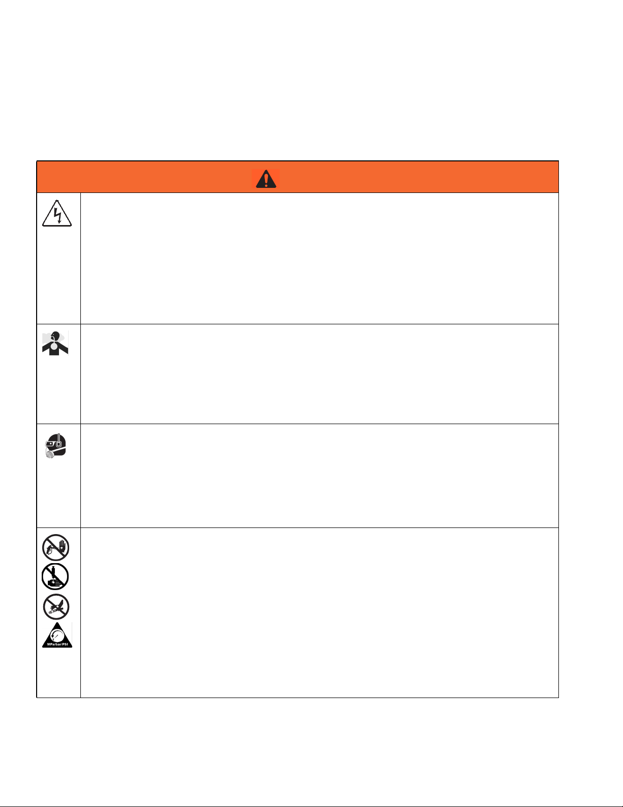
Warnings
The following warnings are for the setup, use, grounding, maintenance, and repair of this equipment. The exclamation point symbol alerts you to a general warning and the hazard symbol refers to procedure-specific risk. Refer back
to these warnings. Additional, product-specific warnings may be found throughout the body of this manual where
applicable.
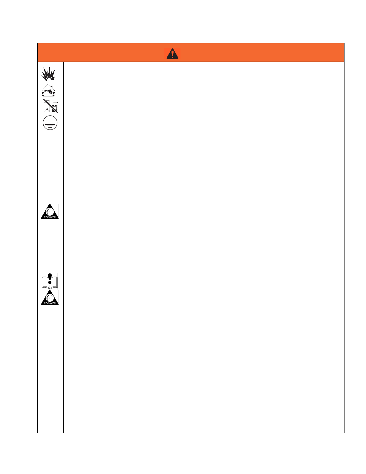
WARNING
ELECTRIC SHOCK HAZARD
This equipment must be grounded. Improper grounding, setup, or usage of the system can cause electric shock.
• Turn off and disconnect power at main switch before disconnecting any cables and before servicing
equipment.
• Connect only to grounded power source.
• All electrical wiring must be done by a qualified electrician and comply with all local codes and regulations.
TOXIC FLUID OR FUMES HAZARD
Toxic fluids or fumes can cause serious injury or death if splashed in the eyes or on skin, inhaled, or
swallowed.
• Read MSDSs to know the specific hazards of the fluids you are using.
• Store hazardous fluid in approved containers, and dispose of it according to applicable guidelines.
• Always wear chemically impermeable gloves when spraying, dispensing, or cleaning equipment.
PERSONAL PROTECTIVE EQUIPMENT
You must wear appropriate protective equipment when operating, servicing, or when in the operating
area of the equipment to help protect you from serious injury, including eye injury, hearing loss, inhalation of toxic fumes, and burns. This equipment includes but is not limited to:
• Protective eyewear, and hearing protection.
• Respirators, protective clothing, and gloves as recommended by the fluid and solvent manufacturer.
SKIN INJECTION HAZARD
High-pressure fluid from dispensing device, hose leaks, or ruptured components will pierce skin. This
may look like just a cut, but it is a serious injury that can result in amputation. Get immediate surgical
treatment.
• Do not point dispensing device at anyone or at any part of the body.
+
• Do not put your hand over the fluid outlet.
• Do not stop or deflect leaks with your hand, body, glove, or rag.
• Follow the Pressure Relief Procedure when you stop dispensing and before cleaning, checking,
or servicing equipment.
• Tighten all fluid connections before operating the equipment.
• Check hoses and couplings daily. Replace worn or damaged parts immediately.
10 3A2176J
Page 11
Warnings
WARNING
FIRE AND EXPLOSION HAZARD
Flammable fumes, such as solvent and paint fumes, in work area can ignite or explode. To help prevent
fire and explosion:
• Use equipment only in well ventilated area.
• Eliminate all ignition sources; such as pilot lights, cigarettes, portable electric lamps, and plastic
drop cloths (potential static arc).
• Keep work area free of debris, including solvent, rags and gasoline.
• Do not plug or unplug power cords, or turn power or light switches on or off when flammable fumes
are present.
• Ground all equipment in the work area. See Grounding instructions.
• Use only grounded hoses.
• Hold gun firmly to side of grounded pail when triggering into pail.
• If there is static sparking or you feel a shock, stop operation immediately. Do not use equipment
until you identify and correct the problem.
• Keep a working fire extinguisher in the work area.
PRESSURIZED EQUIPMENT HAZARD
Fluid from the gun/dispense valve, leaks, or ruptured components can splash in the eyes or on skin and
cause serious injury.
• Follow the Pressure Relief Procedure when you stop spraying and before cleaning, checking, or
servicing equipment.
• Tighten all fluid connections before operating the equipment.
• Check hoses, tubes, and couplings daily. Replace worn or damaged parts immediately.
EQUIPMENT MISUSE HAZARD
Misuse can cause death or serious injury.
• Do not operate the unit when fatigued or under the influence of drugs or alcohol.
• Do not exceed the maximum working pressure or temperature rating of the lowest rated system
component. See Technical Data in all equipment manuals.
• Use fluids and solvents that are compatible with equipment wetted parts. See Technical Data in all
equipment manuals. Read fluid and solvent manufacturer’s warnings. For complete information
about your material, request MSDS from distributor or retailer.
• Do not leave the work area while equipment is energized or under pressure. Turn off all equipment
and follow the Pressure Relief Procedure when equipment is not in use.
• Check equipment daily. Repair or replace worn or damaged parts immediately with genuine manufacturer’s replacement parts only.
• Do not alter or modify equipment.
• Use equipment only for its intended purpose. Call your distributor for information.
• Route hoses and cables away from traffic areas, sharp edges, moving par ts, and hot surfaces.
• Do not kink or over bend hoses or use hoses to pull equipment.
• Keep children and animals away from work area.
• Comply with all applicable safety regulations.
3A2176J 11
Page 12
Warnings
WARNING
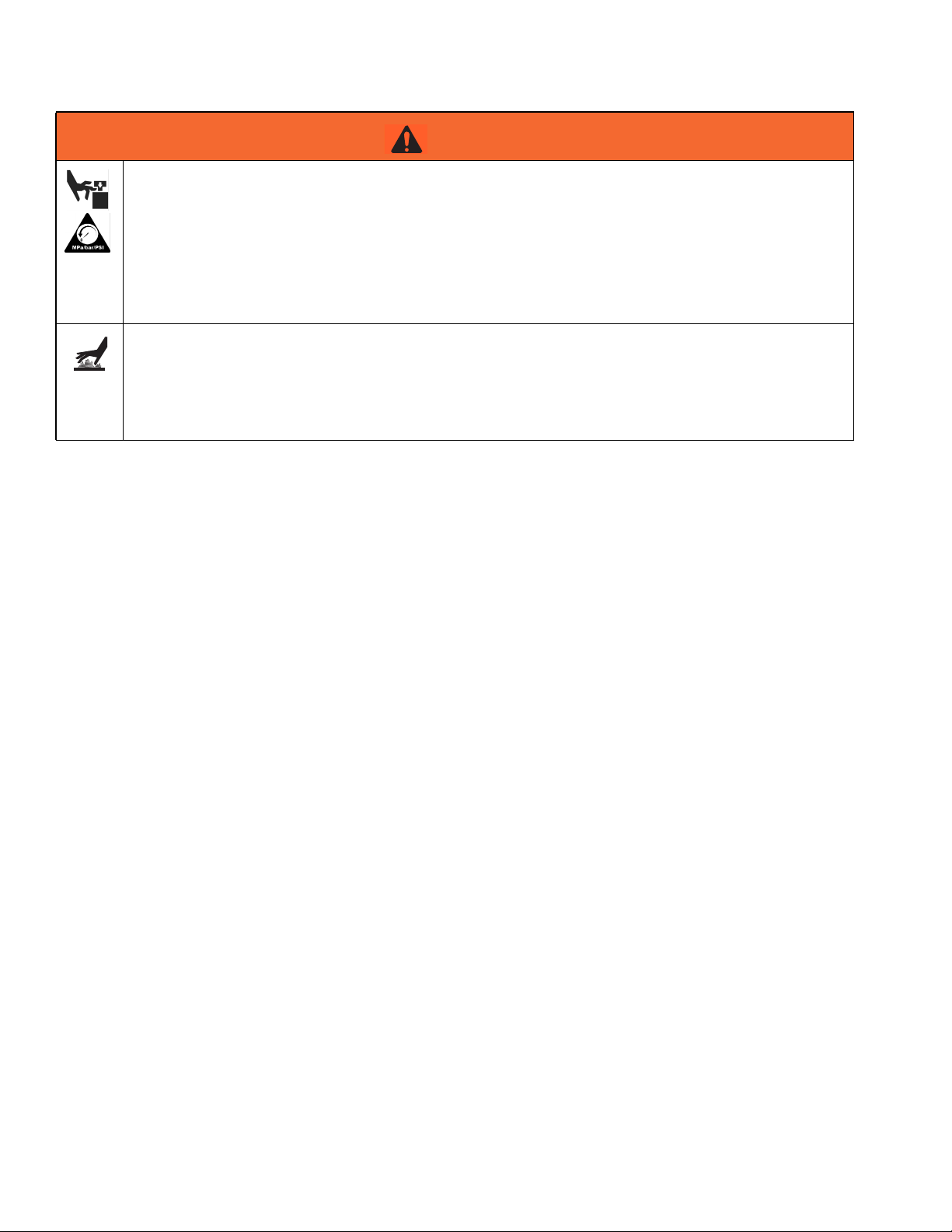
MOVING PARTS HAZARD
Moving parts can pinch, cut or amputate fingers and other body parts.
• Keep clear of moving parts.
• Do not operate equipment with protective guards or covers removed.
• Pressurized equipment can start without warning. Before checking, moving, or servicing equipment, follow the Pressure Relief Procedure and disconnect all power sources.
BURN HAZARD
Equipment surfaces and fluid that’s heated can become very hot during operation. To avoid severe
burns:
• Do not touch hot fluid or equipment.
12 3A2176J
Page 13

Warnings
3A2176J 13
Page 14
Important Two-Component Material Information
Important Two-Component Material Information
Isocyanate Conditions
Spraying or dispensing materials containing isocyanates creates potentially harmful mists, vapors, and
atomized particulates.
Read material manufacturer’s warnings and material
MSDS to know specific hazards and precautions
related to isocyanates.
Prevent inhalation of isocyanate mists, vapors, and
atomized particulates by providing sufficient ventilation in the work area. If sufficient ventilation is not
available, a supplied-air respirator is required for
everyone in the work area.
To prevent contact with isocyanates, appropriate personal protective equipment, including chemically
impermeable gloves, boots, aprons, and goggles, is
also required for everyone in the work area.
Material Self-ignition
Some materials may become self-igniting if applied
too thickly. Read material manufacturer’s warnings
and material MSDS.
Keep Components A (Red) and
Moisture Sensitivity of Isocyanates
Isocyanates (ISO) are catalysts used in two component
foam and polyurea coatings. ISO will react with moisture
(such as humidity) to form small, hard, abrasive crystals,
which become suspended in the fluid. Eventually a film
will form on the surface and the ISO will begin to gel,
increasing in viscosity. If used, this partially cured ISO
will reduce performance and the life of all wetted parts.
NOTE: The amount of film formation and rate of crystallization varies depending on the blend of ISO, the
humidity, and the temperature.
To prevent exposing ISO to moisture:
• Always use a sealed container with a desiccant
dryer in the vent, or a nitrogen atmosphere. Never
store ISO in an open container.
• Keep the ISO lube pump reservoir (if installed) filled
with IsoGuard Select™, part 24F516. The lubricant
creates a barrier between the ISO and the atmosphere.
• Use moisture-proof hoses specifically designed for
ISO, such as those supplied with your system.
• Never use reclaimed solvents, which may contain
moisture. Always keep solvent containers closed
when not in use.
• Never use solvent on one side if it has been contaminated from the other side.
• Always lubricate threaded parts with ISO pump oil
or grease when reassembling.
B (Blue) Separate
Cross-contamination can result in cured material in
fluid lines which could cause serious injury or damage equipment. To prevent cross-contamination of
the equipment’s wetted parts, never interchange
component A (Red) and component B (Blue) parts.
14 3A2176J
Page 15

Changing Materials
• When changing materials, flush the equipment multiple times to ensure it is thoroughly clean.
• Always clean the fluid inlet strainers after flushing.
• Check with your material manufacturer for chemical
compatibility.
• Most materials use ISO on the A (Red) side, but
some use ISO on the B (Blue) side. See the following section.
A (Red) and B (Blue) Components
IMPORTANT!
Material suppliers can vary in how they refer to plural
component materials.
A (Red) and B (Blue) Components
Be aware that when standing in front of the manifold on
proportioner:
• Component A (Red) is on the left side.
• Component B (Blue) is on the right side.
For all machines:
• The A (Red) side is intended for ISO, hardeners,
and catalysts.
• If one of the materials being used is moisture-sensitive, that material should always be in the A (Red)
side.
• The B (Blue) side is intended for polyols, resins, and
bases.
For HFRS Systems:
The high volume material is typically the ISO and is
located on the A (Red) side. Some material chemistries
may have an ISO which is the low volume material. The
ISO must always be in the A (Red) side containing the
Isolube.
NOTE: For HFRL Systems:
The high volume material will always be the B (Blue)
side.Typical Installation
3A2176J 15
Page 16
Operation
Operation
Shutdown
1. Park pumps.
a. From the Home screen, press and select
Standby mode.
b. Press . Material will dispense. Pump will
park automatically. Once pump is parked, pump
will stop moving.
If a dispense gun with a trigger is installed,
pulling the trigger will begin a park operation.
Material will dispense.
2. Press the enable/disable key on the ADM to
disable the ADM.
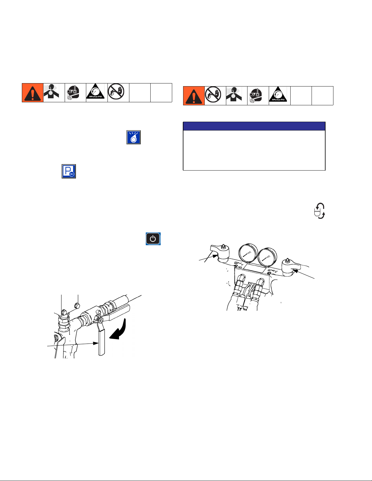
Pressure Relief Procedure
NOTICE
The fittings on the pressure relief hoses are zinc
plated carbon steel. The hose cores are cured with
sulfur. Check your materials for compatibility with
zinc plating and sulfur before reusing any material
that passed through them, as it may inhibit curing.
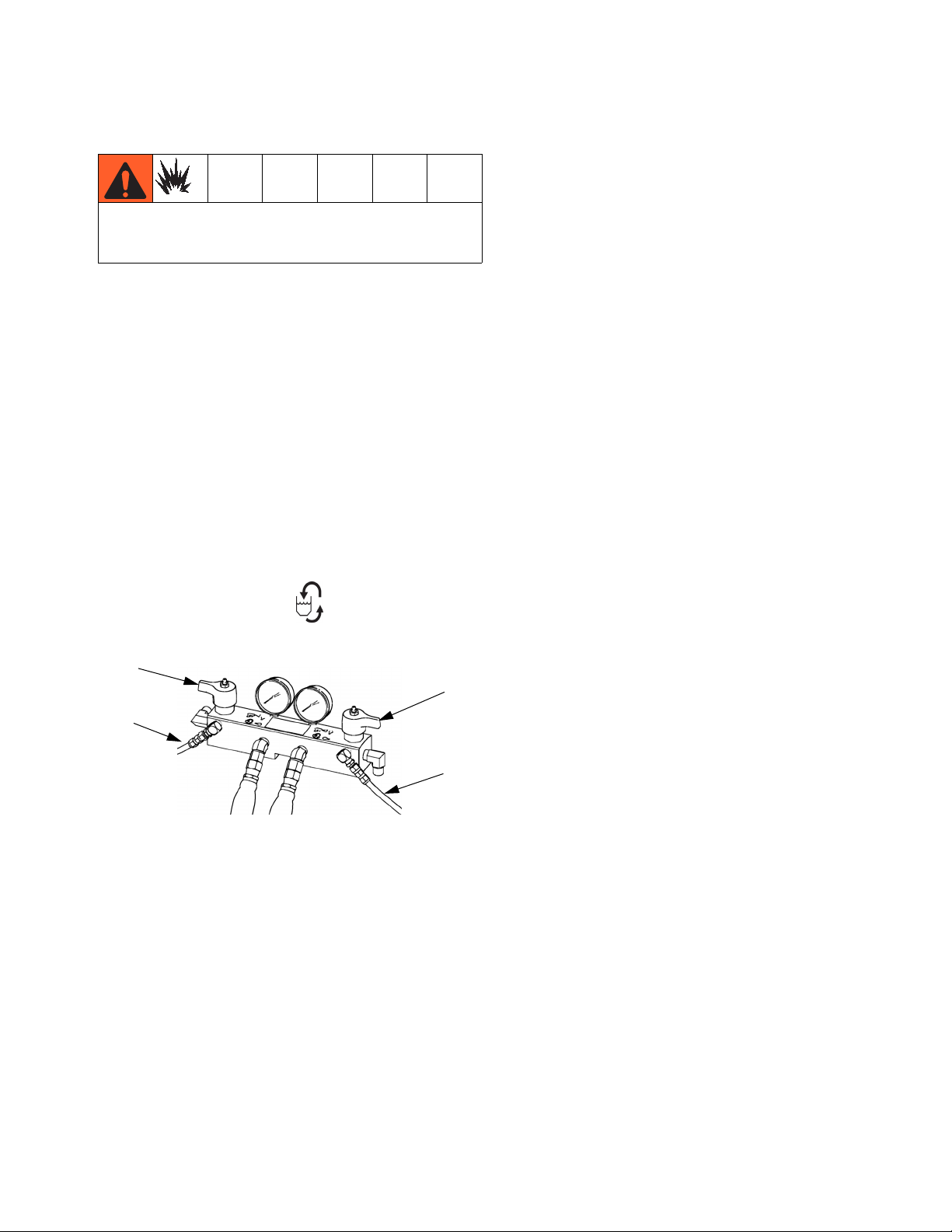
1. Shut off feed pumps and agitator, if used.
2. Turn PRESSURE RELIEF/DISPENSE valves (SA,
SB) to PRESSURE RELIEF/CIRCULATION .
Route fluid to waste containers or supply tanks.
Ensure gauges drop to 0.
3. Turn main power switch (MP) to OFF position.
4. Close A (Red) and B (Blue) fluid supply valves (FV),
if equipped, or remove fluid pressure at supply
device.
FV
ti9883a1
5. Perform Pressure Relief Procedure on page 16.
6. Shut down feed pumps as required. See feed pump
manual.
SA
SB
ti9879a1
3. For models with an dispense valve with a safety
lock, engage gun safety lock.
4. Relieve pressure in dispense valve. See dispense
valve manual.
16 3A2176J
Page 17
Operation
Flushing
Flush equipment only in a well-ventilated area. Do not
dispense flammable fluids. Do not turn on heaters
while flushing with flammable solvents.
• Flush out old fluid with new fluid, or flush out old
fluid with a compatible solvent before introducing
new fluid.
• Use the lowest possible pressure when flushing.
• All fluid components are compatible with common
solvents. Use only moisture-free solvents. See
Technical Data on page 70 for list of wetted components to verify compatibility of solvent with wetted
materials. See solvent manufacturers information for
material compatibility.
• To flush feed hoses, pumps, and heaters separately
from heated hoses, set PRESSURE RELIEF/DISPENSE valves (SA, SB) to PRESSURE
• To maintain grounding continuity when flushing or
relieving pressure, hold a metal part of dispense
gun firmly to the side of a grounded metal pail, then
trigger gun.
RELIEF/CIRCULATION . Flush through bleed
lines (N).
SA
SB
N
N
ti9880a1
• To flush entire system, circulate through gun fluid
manifold (with manifold removed from gun).
• To prevent moisture from reacting with isocyanate,
always leave the system dry or filled with a moisture-free plasticizer or oil. Do not use water. See
Important Two-Component Material Information
on page 14.
• Solvent pails used when flushing: follow your local
code. Use only metal pails, which are conductive,
placed on a grounded surface. Do not place pail on
a nonconductive surface, such as paper or cardboard, which interrupts grounding continuity.
3A2176J 17
Page 18
Repair
Repair
Pumpline
See Z-Series Chemical Pumps manual, HFR Hydraulic
Driver manuals for more detailed pumpline repair information.
Remove Chemical Pumps
This procedure removes the chemical pumps so that
replacement parts can be installed. See Z-Series Chemical Pumps manual for replacement parts installation
procedure.
1. Flush system, see page 17.
2. Perform Operation, see page 16.
3. Remove the front pump shroud.
4. Disconnect the chemical pump inlet and outlet fluid
lines. Do not disconnect the fluid manifold inlet line
or the fluid line connections at the heater.
Fluid Manifold Inlet
Pump Outlet
Pump Inlet
24C352_313998_4g1
18 3A2176J
Page 19
Repair
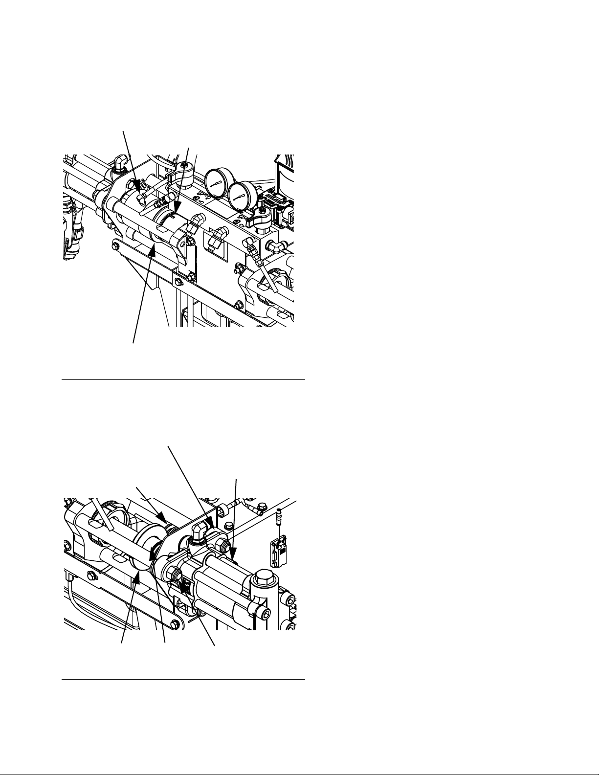
5. Unthread smaller cylinder from hydraulic driver and
slide inside larger cylinder. Use punch slots in lube
cylinder to aid rotation if necessary. See FIG.1.
Lube Cylinder Outlet Fitting
Punch Slot (same on opposite side)
24C352_313998_2g1
Lube Cylinder Inlet Fitting (behind cylinder)
7. Remove coupler from the A and B side pump shafts.
See FIG.2.
8. Unscrew LVDT sensor assembly and spool assembly from pump outlet housing. Wipe off spool
assembly. See F
IG.2.
9. Remove three nuts securing pump to tie rods. See
F
IG.2.
FIG. 1: Lube Cylinder
6. Remove two shoulder bolts from LVDT collar then
remove collar from B side pump shaft. See FIG.2.
Pump Outlet Housing
LVDT Sensor Assembly
(behind pump)
LVDT Spool Assembly
24C352_313998_2g1
LVDT Collar
Coupler
Nuts
FIG.2
3A2176J 19
Page 20
Repair
Install Chemical Pumps
Reconnect or install a different size chemical pump to
achieve desired ratio.
1. Install ISO lube cylinder on A side pump. Apply light
coating of lubricant on o-rings on outside of small
cylinder.
2. Install nuts on tie rods after the pumps have been
installed. Torque to 50-60 ft-lb (68-81 N•m).
3. Install coupler on A and B side pump shafts.
4. Install LVDT Assembly.
a. Apply a very light coat of hydraulic oil on LVDT
sensor tube and install through pump outlet
housing. Install spool assembly.
b. Install LVDT collar on coupler and pump shaft.
Ensure that the split on the LVDT collar does not
ride in the spool assembly.
c. Apply thread sealant to shoulder bolts then
install in LVDT collar. Torque to 40-50 in-lb
(4.5-5.6 N•m).
Prime IsoGuard Select™Cylinder
24C352_313998_8g1
FIG. 3: IsoGuard Select System
NOTE: The IsoGuard Select cylinder is installed on all
HFRL systems and is available separately as kit
24M154 for HFRS systems.
5. After the IsoGuard Select cylinder has been
installed on the A side pump, apply pipe sealant on
cylinder outlet fitting.
6. Perform Prime IsoGuard Select™Cylinder procedure, see page 20.
7. Reconnect inlet and outlet fluid lines.
Ensure that the IsoGuard Select cylinder outlet faces
upward for air to exhaust.
1. Install IsoGuard Select cylinder inlet fitting and inlet
tube into bottom of cylinder. The inlet tube is the
tube with a check valve installed in it which points in
the direction of flow towards the IsoGuard Select
cylinder.
2. Install IsoGuard Select cylinder outlet fitting and outlet tube into top of cylinder. The outlet tube is the
tube with a check valve installed in it which points in
the direction of flow away from the IsoGuard Select
cylinder.
3. Remove check valve from end of outlet tube.
4. Use funnel to pour IsoGuard Select into tube to fill
cylinder.
5. With check valve arrow pointing away from the
IsoGuard Select cylinder, install check valve in end
of outlet tube.
6. Install tubes into reservoir and install reservoir into
holder.
20 3A2176J
Page 21
Repair
Remove HFR Hydraulic Driver
D88
24C352_313998_5g1
FIG.4
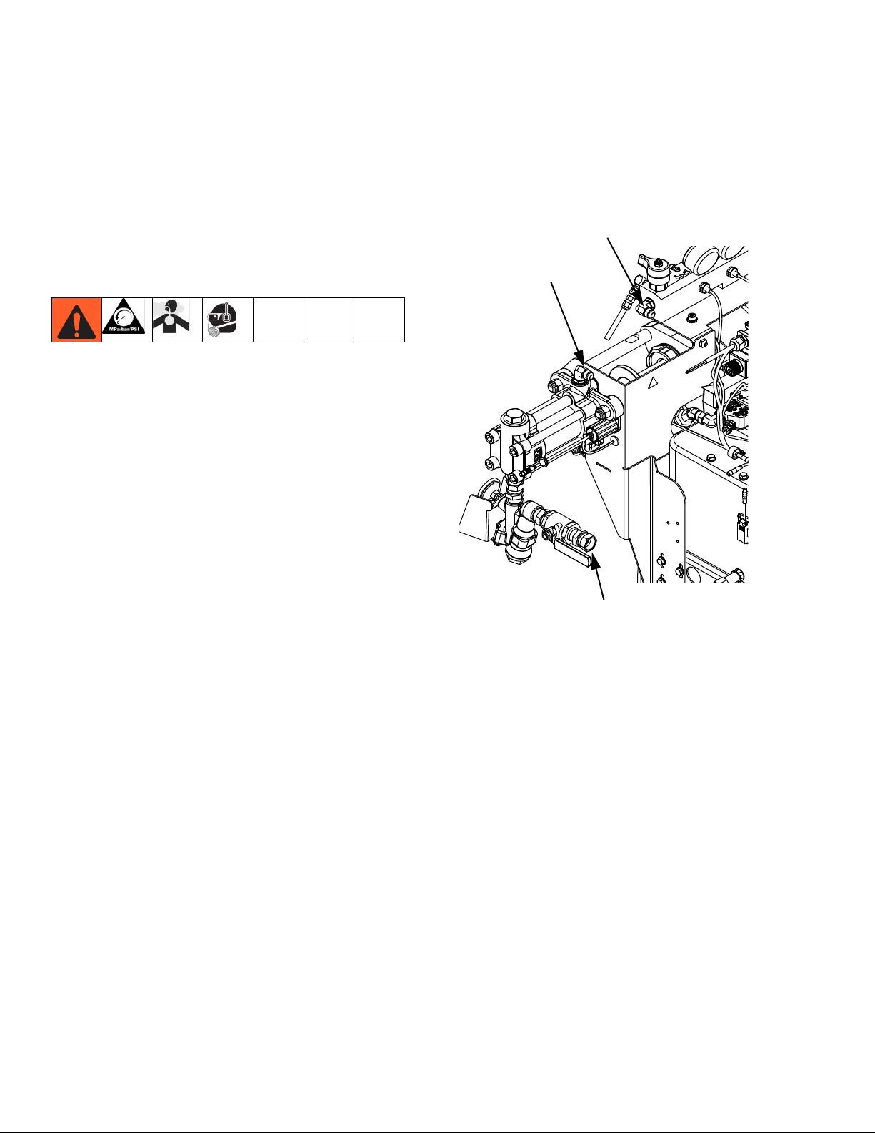
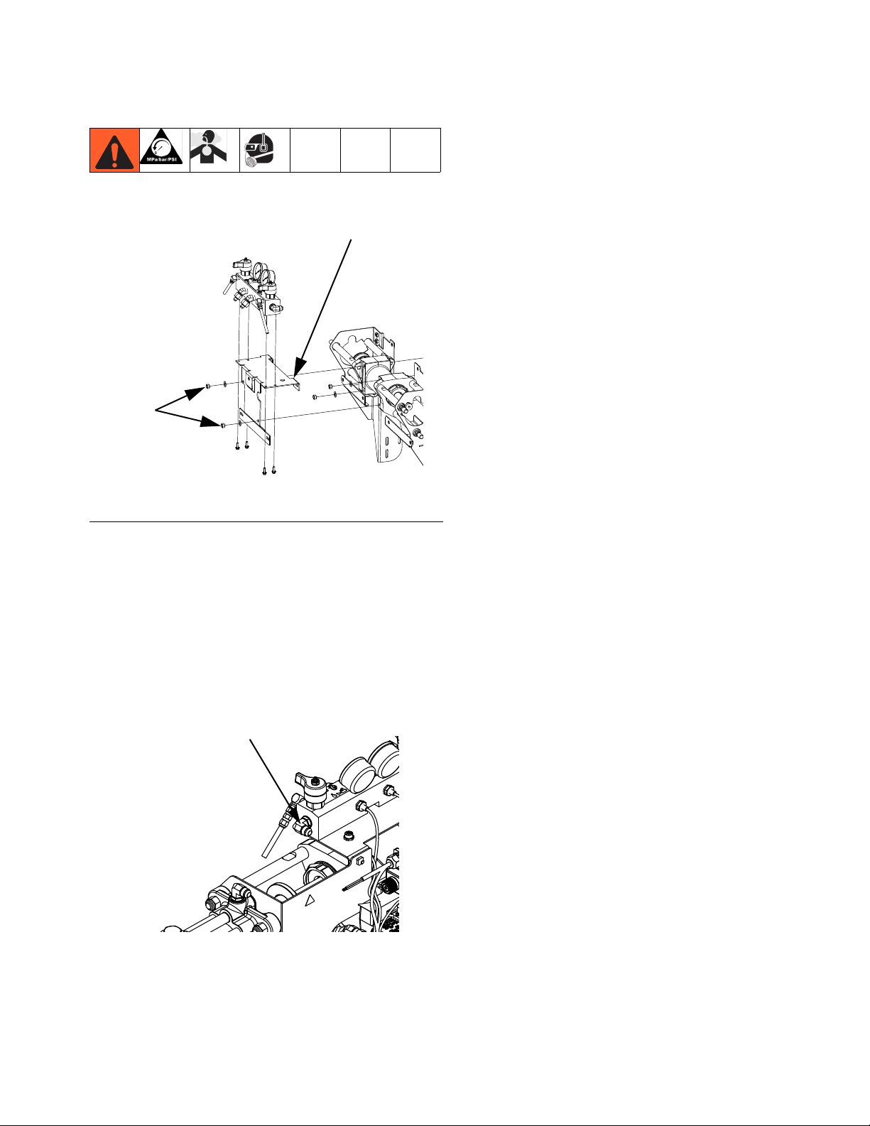
4. See FIG.4. Remove four nuts (D88) securing
hydraulic driver to hydraulic power pack. This will
also loosen manifold plate (MP) from hydraulic
driver. Remove manifold plate. Remove hydraulic
driver.
Install HFR Hydraulic Driver
MP
This procedure installs the hydraulic driver after replacement parts have been installed and actuator has been
reassembled. See HFR Hydraulic Driver manual for
replacement parts installation procedure.
1. Hang the hydraulic driver on the studs. Verify o-rings
between driver and hydraulic power pack are
installed and lubricated. Secure the driver with nuts
and washer at bottom-left and top-right corners.
2. Install manifold bracket. Secure at top-left and bottom-right corners.
3. Install pump support brackets, torque to 300 in-lb
(33.9 N•m). This will also install manifold plate (MP)
to hydraulic driver.
4. Connect fluid manifold inlet lines.
This procedure removes the HFR Hydraulic Driver so
replacement parts can be installed. See HFR Hydraulic
Driver manual for replacement parts installation procedure.
1. Perform Remove Chemical Pumps procedure, see
page 18.
2. Disconnect the fluid manifold inlet lines. Do not disconnect the fluid line connections at the heater.
Fluid Manifold Inlet
24C352_313998_4e1
5. Perform Install Chemical Pumps procedure, see
page 20.
3. Remove pump support brackets. Each bracket is
secured with three screws at the base frame and
two screws at the manifold bracket.
3A2176J 21
Page 22
Repair
Remove PowerHouse Pumpline
The Hydraulic Power Pack must be removed to perform
some Hydraulic Power Pack repair procedures. In order
to remove the Hydraulic Power Pack, the PowerHouse
pumpline must be removed. See Hydraulic Power
Pack Repair starting on page 25 for more information.
1. Perform Operation procedure, see page 16.
2. Flush the system, see page 17.
3. Disconnect the chemical pump inlet, pump outlet,
and fluid manifold inlet lines. Do not disconnect the
fluid line connections at the heater.
Fluid Manifold Inlet
Pump Outlet
4. Remove lube cylinder inlet and outlet fittings. Let
cylinder drain.
Punch Slot (same on opposite side)
Lube Cylinder Outlet Fitting
24C352_313998_8e1
Lube Cylinder Inlet Fitting
FIG. 5: Lube Cylinder, Viewed from Rear Left of
Machine
Pump Inlet
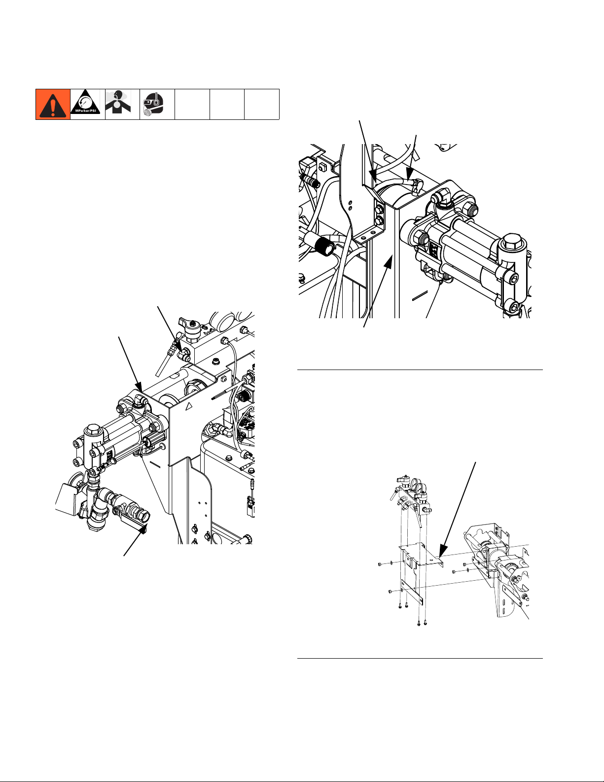
5. See FIG.6. Remove four screws securing pumpline
to hydraulic power pack. This will also loosen manifold plate (MP) from hydraulic driver.
MP
24C352_313998_4e1
24C352_313998_5g1
FIG.6
22 3A2176J
Page 23

6. While supporting the pumpline, remove the three
bolts on each side of the machine securing the
pump support brackets to the machine base. See
FIG.7. Remove pumpline.
Repair
FIG.7
24C352_313998_4e1
3A2176J 23
Page 24

Repair
Install PowerHouse Pumpline
The Hydraulic Power Pack must be removed to perform
some Hydraulic Power Pack repair procedures. In order
to remove the Hydraulic Power Pack, the PowerHouse
pumpline must be removed. This procedure is for installing the PowerHouse pumpline at the end of the Hydraulic Power Pack Repair procedure. See Hydraulic Power
Pack Repair starting on page 25 for more information.
1. While supporting the pumpline, install the three
bolts on each side of the machine securing the
pump support brackets to the machine base. See
FIG.7. Torque to 150 in-lb (16.9 N•m).
2. See FIG.6. Align manifold plate (MP) with hydraulic
driver. Align hydraulic driver with hydraulic power
pack. Install four screws securing hydraulic driver to
hydraulic power pack. This will also install manifold
plate (MP) to hydraulic driver. Torque to 300 in-lb
(33.9 N•m).
3. Install lube cylinder inlet and outlet fittings. See FIG.
5. Apply thread sealant to threads.
4. Perform Prime IsoGuard Select™Cylinder procedure, see page 20.
5. Connect the chemical pump inlet, pump outlet, and
fluid manifold inlet lines.
Fluid Manifold Inlet
Pump Outlet
24C352_313998_4e1
Pump Inlet
24 3A2176J
Page 25

Hydraulic Power Pack Repair
Repair
H15
H16
H04
H14
H09
H12
H13
H08
H24
H35
11 26
8
2
12
H34
H21, H22
11
5
11
H46
6
7
14
11
6
11
H28
H30H33H32H31H45
11
15
H29
H18
2
10
3
11
10
2
12
2
12
10
11
3
9
13
H17
H19
H06
H05
H10
H11
H23
H25
12
5
11
H21,
H27
H44
4
11
H37
2
12
H26
H01
H38
11
8
9
12
10
H07
H02
5
11
257442_3A0998_1j
H02
H20
1
Assemble coupler to specified dimensions
prior to mounting assembly to housing.
2
Torque to 40 ft-lb (54 N•m).
3
Torque to 35 ft-lb (47 N•m).
4
Torque to 20 ft-lb (27 N•m).
5
Torque to 15 ft-lb (20 N•m).
6
Torque to 10 ft-lb (14 N•m).
7
Torque to 58 in-lb (6.5 N•m).
+.00
.45
-.02
H02
1
8
Torque to 34 in-lb (3.8 N•m).
9
Torque 1/4 turn past hand-tight.
10
Apply PTFE tape on installation end only.
11
Apply medium strength thread locker before
assembly.
12
Apply light coating of lubricant to seals.
13
Fill reservoir with hydraulic fluid.
1
+.01
.30
-.00
14
Orient with airflow arrow pointing toward
mounting bracket.
15
Prior to installing Ref. 728 into Ref. 726,
install Ref. 729 into Ref. 728 and adjust
head 1/8 in. from surface.
24
Align fan plug as shown.
26
Apply thermal lubricant to contact side.
H31
24
FIG. 8: Hydraulic DC Power Pack
3A2176J 25
Page 26

Repair
Remove Hydraulic Power Pack Shroud
1. Remove four screws from base of shroud.
2. Lift shroud off of Hydraulic Power Pack.
Install Hydraulic Power Pack Shroud
NOTICE
Do not over-torque any item that threads into the
hydraulic tank. This will strip the threads and
require tank replacement.
1. Place shroud on top of Hydraulic Power Pack.
2. Install four screws securing shroud to hydraulic tank.
Replace Hydraulic Filter
Filter is located at right rear of hydraulic power pack.
See FIG.8on page 25.
NOTICE
If any debris falls into the hydraulic tank, the debris
must be removed or machine damage will result.
3. Remove four screws (H32) connecting fan to mounting plate.
4. Remove fan and install new fan.
5. Install four screws (H32) connecting fan to Motor
and Motor Control Module.
6. Install Hydraulic Power Pack Shroud, see procedure on this page.
Remove Motor Control Module
See FIG.8on page 25.
1. Perform Operation procedure, see page 16.
2. Remove Hydraulic Power Pack Shroud, see procedure on this page.
3. Remove four screws (H32) connecting fan to Motor
and Motor Control Module. Remove fan and mounting plate.
1. Perform Operation procedure, see page 16.
2. Use compressed air to remove any loose debris
around the hydraulic filter.
3. Remove new filter from wrapping.
4. Apply a light coat of hydraulic fluid to the o-ring on
the face of the hydraulic filter.
5. Being careful not to allow any debris into the
hydraulic tank remove old filter from tank then
quickly install new filter.
Replace Fan
See FIG.8on page 25.
1. Perform Operation procedure, see page 16.
2. Remove Hydraulic Power Pack Shroud, see procedure on this page.
4. Note the location of each Motor Control Module
cable then remove all electrical cables on the left
and right sides of the Motor Control Module.
5. Remove six screws (H29) securing Motor Control
Module in place.
6. Slowly and carefully slide the Motor Control Module
up until the cable on the bottom of the Motor Control
Module can be accessed and removed. Disconnect
the cable.
7. Slide the Motor Control Module up and remove.
26 3A2176J
Page 27

Adjust Motor Control Module Selector
Switch
NOTICE
Repair
If the Motor Control Module is replaced, the selector switch must be set prior to initial startup of the
Motor Control Module or damage may occur.
The Motor Control Module uses an 8-position selector
switch (S) to set system maximum working pressure.
See FIG.9.
The system can be configured to run in two pressure
ranges:
• 0-3000 psi (0-20.7 MPA, 0-207 bar): For systems
will all components rated to 3000 psi maximum
working pressure or higher.
• 0-2000 psi (0-13.8 MPA, 0-138 bar): For systems
with one or more component rated less than
3000 psi maximum working pressure. For example,
if the dispense valve is rated to 2500 psi, then the
0-2000 psi range must be used.
NOTE:The Motor Control Module selector switch (S)
position #1 sets the system to 2000 psi maximum
working pressure. Selector switch position #3 sets
the system to 3000 psi maximum working pressure.
The factory setting for the Motor Control Module selector
switch is position #1 to set the machine to 2000 psi if the
machine is shipped with no hoses or hoses rated to
2000 psi maximum working pressure. If the machine is
shipped with hoses rated to 3000 psi maximum working
pressure or higher then the factory setting for the selector switch is position #3 to set the machine to 3000 psi.
• Do not install components rated to less than the
highest pressure in the selected pressure range.
For example, if the 0-2000 psi range is selected do
not install items rated less than 2000 psi. If the
0-3000 psi range is selected do not install items
rated less than 3000 psi. Doing so may lead to
overpressurization and ruptured components.
• High-pressure fluid from ruptured components will
pierce skin. This may look like just a cut, but it is a
serious injury that can result in amputation. Get
immediate surgical treatment.
To set the Motor Control Module selector switch:
1. Turn machine power off.
2. Remove the access cover (D). See FIG.9.
3. Set the selector switch (S).
4. Install access cover (D).
D
S
257396_3b9905_04b
FIG.9
The selector switch position will be properly set at the
factory for new systems. When a motor control module
is replaced, the selector switch must be set to the correct setting by the user prior to initial startup.
To change the maximum working pressure rating of the
system in the field, all outlet components including
hoses and dispense valve must be rated at or above the
new system maximum working pressure rating. For
example, if the new system rating will be 3000 psi, all
system components must be rated to at least 3000 psi
maximum working pressure.
3A2176J 27
Page 28

Repair
Install Motor Control Module
This procedure starts assuming that the old Motor Control Module is removed from the machine. See Remove
Motor Control Module procedure, see page 26.
See FIG.8on page 25.
1. Perform Adjust Motor Control Module Selector
Switch procedure on page 27.
NOTICE
Motor Control Module selector switch position must
be set prior to startup of Motor Control Module or
damage may occur.
2. Slide the Motor Control Module into the slot.
3. Attach the cable on the bottom of the Motor Control
Module.
4. Install the six screws (H29) securing Motor Control
Module in place.
This procedure removes the hydraulic power pack from
the machine as a single unit to enable further disassembly. User must purchase three 5/16-18 eye-bolts capable
of holding 300 lb to perform this procedure.
See FIG.8on page 25.
1. Perform Operation procedure, see page 16.
2. Perform Remove Hydraulic Power Pack Shroud,
see procedure on page 26.
3. Perform Remove Motor Control Module procedure, see page 26.
4. Perform Remove PowerHouse Pumpline proce-
dure, see page 22.
5. Disconnect heat exchanger inlet hose and fitting
from elbow fitting. Disconnect heat exchanger outlet
hose and fitting from elbow fitting.
6. Remove the two bolts (H46) from the fluid
housing (H03) and replace each with a strong
5/16-18 thread eye-bolt. Install a third strong
5/16-18 eye-bolt as indicated. See FIG.10. See FIG.
8 on page 25 for full hydraulic power pack view.
H03 H46
5. Install electrical cables on left and right sides of the
Motor Control Module.
6. Install four screws (H32) connecting fan to Motor
and Motor Control Module. Install fan and mounting
plate.
7. Install Hydraulic Power Pack Shroud, see procedure on page 26.
Remove Hydraulic Power Pack
The hydraulic power pack weighs up to 300 lb. To
avoid serious injury due the hydraulic power pack falling, secure the hydraulic lift when raising the hydraulic
power pack.
NOTICE
If any debris falls into the hydraulic tank, the debris
must be removed or machine damage will result.
H46
257442_313998_1j1
Install third eye-bolt here
FIG.10
7. Run a rope through the three eye-bolts and between
the motor and the Motor Control Module. Secure to
a hydraulic lift.
8. Remove the four bolts and washers securing the
tank to the electrical enclosure. See Power Pack
Module on page 44.
9. Lift the hydraulic power pack and place on a sturdy
location capable of supporting up to 300 lbs.
28 3A2176J
Page 29

Repair
Install Hydraulic Power Pack
NOTICE
If any debris falls into the hydraulic tank, the debris
must be removed or machine damage will result.
NOTICE
Do not over-torque any item that threads into the
hydraulic tank. This will strip the threads and
require tank replacement.
This procedure assumes the Hydraulic Power Pack has
been removed from the machine and is assembled
except for the Motor Control Module.
See FIG.8on page 25.
1. Run a rope through the three eye-bolts and between
the Motor and the Motor Control Module. Secure to
a hydraulic lift.
2. Lift the Hydraulic Power Pack and place onto the
electronic enclosure.
3. Align the holes with the tank then install finger-tight
the four bolts and washers securing the tank to the
electrical enclosure. Torque to 10 ft-lb (14 N•m).
Replace Tank Gasket, Tank
See FIG.8on page 25.
1. Perform Remove Hydraulic Power Pack procedure, see page 28.
2. Remove hex head cap screws (H22) securing
hydraulic housing (H03) to tank (H20). Carefully
remove motor (H01) and hydraulic housing assembly from tank.
3. Remove tank gasket. If tank is damaged, replace
tank.
NOTICE
Do not over-torque any item that threads into the
hydraulic tank. This will strip the threads and
require tank replacement.
4. Install thrust washers (H21) onto hex head cap
screws. Apply pipe sealant to threads of screws.
Align tank gasket (H19), hydraulic housing, and
tank (H20) then install screws. Torque to 15 ft-lb (20
N•m).
5. Perform Install Hydraulic Power Pack procedure,
see page 29.
4. Remove rope and lift.
5. Remove eye-bolts. Install original bolts (H46) into
fluid housing (H03). See FIG.10.
6. Perform Install PowerHouse Pumpline procedure,
see page 24.
7. Perform Install Motor Control Module procedure,
see page 28.
8. Connect heat exchanger inlet hose and fitting to
elbow fitting. Connect heat exchanger outlet hose
and fitting to elbow fitting located on rear right face
of tank. See Power Pack Module on page 44.
3A2176J 29
Remove Motor
See FIG.8on page 25.
1. Perform Remove Hydraulic Power Pack procedure, see page 28.
2. Remove four hex head cap screws (H22) securing
hydraulic housing (H03) and motor (H01) to tank.
Carefully remove motor and hydraulic housing
assembly from tank.
3. Remove four hex head cap screws (H27) connecting mounting bracket (H26) to motor.
4. Remove four socket head cap screws (H04) securing motor to hydraulic housing. Carefully remove
motor from hydraulic housing.
Page 30

Repair
5. Loosen set screw for motor coupler (H02) then
remove motor coupler.
Install Motor
See FIG.8on page 25.
1. Use four hex head cap screws (H27) and thrust
washers (H21) to install Motor Control Module
mounting bracket (H26) onto motor (H01).
2. Install motor coupler (H02) onto motor (H01). Coupler must be 0.65-0.67 in. from the face of the
motor. Torque motor coupler set screw to 15 ft-lb
(20 N•m).
3. Install spider coupler (H07) into motor coupler.
4. Use four socket head cap screws (H04) to attach
hydraulic housing (H03) to motor. Be sure to align
teeth of gear coupler with the teeth of the motor coupler. Apply pipe sealant to threads of screws. Torque
to 35 ft lb (47 N•m).
Remove Hydraulic Gear Pump
See FIG.8on page 25.
1. Perform Remove Hydraulic Power Pack procedure, see page 28.
2. Remove hex head cap screws (H22) securing
hydraulic housing (H03) to tank. Carefully remove
motor (H01) and hydraulic housing assembly.
3. Remove tube (H11).
4. Remove elbow fittings (H10, H12) from gear
pump (H05).
5. Remove two hex head cap screws (H08) securing
gear pump to hydraulic housing.
6. Remove spider coupler (H07).
7. Loosen set screw for gear coupler (H06) then
remove gear coupler from gear pump.
NOTICE
Do not over-torque any item that threads into the
hydraulic tank. This will strip the threads and
require tank replacement.
5. Install thrust washers (H21) onto hex head cap
screws (H22). Apply pipe sealant to threads of
screws. Align tank gasket (H19), hydraulic housing,
and tank (H20) then install screws. Torque to 15 ft-lb
(20 N•m).
6. Perform Install Hydraulic Power Pack procedure,
see page 29.
Install Hydraulic Gear Pump
See FIG.8on page 25.
1. Install gear coupler (H06) onto gear pump (H05).
Coupler must be 0.12 to 0.13 in. from the face of the
gear pump. Torque gear coupler set screw to 15 ft-lb
(20 N•m).
2. Install spider coupler (H07) into gear coupler.
3. Use two hex head cap screws (H08) to attach gear
pump to hydraulic housing. Be sure to align teeth of
gear coupler with the teeth of the motor coupler.
Torque screws to 35 ft-lb (47 N•m).
4. Apply a light coat of lubricant to seals of elbow
fittings (H10, H12). Install elbow fittings into gear
pump. See FIG.8on page 25. for fitting alignment.
Torque both fittings to 40 ft-lb (54 N•m).
30 3A2176J
Page 31

Repair
5. Apply a light coating of lubricant to seals of
tube (H11). Install tube (H11) onto elbow
fitting (H10) and straight fitting (H09). Hand-tighten
then use wrench to tighten 90 degrees further.
NOTICE
Do not over-torque any item that threads into the
hydraulic tank. This will strip the threads and
require tank replacement.
6. Install thrust washers (H21) onto hex head cap
screws (H22). Apply pipe sealant to threads of
screws. Align tank gasket (H19), hydraulic housing,
and tank (H20) then install screws. Torque to 15 ft-lb
(20 N•m).
7. Perform Install Hydraulic Power Pack procedure,
see page 29.
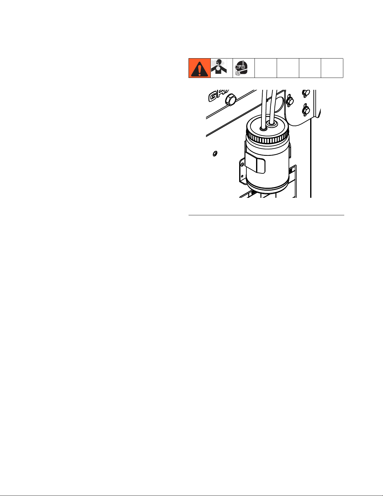
Replace Power Supply
7. Replace electrical enclosure door and turn on system power.
1c
1a
1d
ti18255a
Replace Circuit Breaker
1. Turn off system power.
2. Remove electrical enclosure door.
3. Disconnect power supply (1a) wires from the filter
(1c) splitter connector (1d).
4. Remove nuts and washers that secure the power
supply to the electrical enclosure.
5. Install new power supply to electrical panel. Secure
with nuts and washers.
6. Connect power supply wires to the filter and the
splitter connector.
1. Turn off system power.
2. Remove electrical enclosure door.
3. Disconnect wire harnesses from circuit breaker.
4. Remove circuit breaker.
5. Install new circuit breaker and connect wire harnesses.
6. Replace electrical door and turn on system power.
wire harness
circuit
breaker
wire harness
ti18255a
3A2176J 31
Page 32

Parts
Parts
HFRL Models
007
005
001
004
003
015
015
008,
009,
010
018
002
006
ti18209a
005
016
018
018
017
018
017
FIG. 11: HFRL Models
32 3A2176J
ti18271a
Page 33

Ref
001
002
003
004
005
006
007
008
009
010
011
015
016
017
Part
---
24M034
24M035
L020S1
L025S1
L030S1
L040S1
L050S1
L060S1
L065S1
L080S1
L086S1
L100S1
L160S1
L050S1
L060S1
L065S1
L080S1
L086S1
24M167
24M102
24M099
24M106
255179
24E505
24E250
120955
24M129
24M154
16A093
Description
MODULE, base, HFR, silicone, laminate
MODULE, power, HFR, 230v/1ph
MODULE, power, HFR, 400v/3ph, CE
LOWER, chemical, 20, SST, ucup
LOWER, chemical, 25, SST, ucup
LOWER, chemical, 30, SST, ucup
LOWER, chemical, 40, SST, ucup
LOWER, chemical, 50, SST, ucup
LOWER, chemical, 60, SST, ucup
LOWER, chemical, 65, SST, ucup
LOWER, chemical, 80, SST, ucup
LOWER, chemical, 86, SST, ucup
LOWER, chemical, 100, SST, ucup
LOWER, chemical, 160, SST, ucup
LOWER, chemical, 50, SST, ucup
LOWER, chemical, 60, SST, ucup
LOWER, chemical, 65, SST, ucup
LOWER, chemical, 80, SST, ucup
LOWER, chemical, 86, SST, ucup
MODULE, outlet, fluid, HFR, CS
KIT, hose, 1/4x15, CS, b
KIT, hose, 3/8x15, CS, b
KIT, hose, 3/8x15, CS, a
KIT, orifice block
KIT, orifices, 1/4”
CORD SET, euro, male, 4pin, 3wire, 4m
KIT, assembly, inlet, lamination
KIT, lube, ISO, HFR
HFRL01 1 1 1 1 1 1 1 1 2 1 1 2 1 2 4
VALVE, dispense, 1:1, soft seats
HFRL02 1 1 1 1 1 1 1 1 2 1 1 2 1 2 4
HFRL03 1 1 1 1 1 1 1 1 2 1 1 2 1 2 4
HFRL04 1 1 1 1 1 1 1 1 2 1 1 2 1 2 4
HFRL05 1 1 1 1 1 1 1 1 2 1 1 2 1 2 4
HFRL06 1 1 1 1 1 1 1 1 2 1 1 2 1 2 4
HFRL07 1 1 1 1 1 1 1 1 2 1 1 2 1 2 4
HFRL08 1 1 1 1 1 1 1 1 2 1 1 2 1 2 4
HFRL09 1 1 1 1 1 1 1 1 2 1 1 2 1 2 4
HFRL10 1 1 1 1 1 1 1 1 2 1 1 2 1 2 4
HFRL11 1 1 1 1 1 1 1 1 2 1 1 2 1 2 4
HFRL12 1 1 1 1 1 1 1 1 2 1 1 2 1 2 4
HFRL13 1 1 1 1 1 1 1 1 2 1 1 2 1 2 4
HFRL14 1 1 1 1 1 1 1 1 2 1 1 2 1 2 4
HFRL15 1 1 1 1 1 1 1 1 2 1 1 2 1 2 4
HFRL16 1 1 1 1 1 1 1 1 2 1 1 2 1 2 4
HFRL17 1 1 1 1 1 1 1 1 2 1 1 2 1 2 4
HFRL18 1 1 1 1 1 1 1 1 2 1 1 2 1 2 4
HFRL19 1 1 1 1 1 1 1 1 2 1 1 2 1 2 4
HFRL20 1 1 1 1 1 1 1 1 2 1 1 2 1 2 4
HFRL21 1 1 1 1 1 1 1 1 2 1 1 2 1 2 4
HFRL22 1 1 1 1 1 1 1 1 2 1 1 2 1 2 4
HFRL23 1 1 1 1 1 1 1 1 2 1 1 2 1 2 4
HFRL24 1 1 1 1 1 1 1 1 2 1 1 2 1 2 4
HFRL25 1 1 1 1 1 1 1 1 2 1 1 2 1 2 4
HFRL26 1 1 1 1 1 1 1 1 2 1 1 2 1 2 4
HFRL27 1 1 1 1 1 1 1 1 2 1 1 2 1 2 4
HFRL28 1 1 1 1 1 1 1 1 2 1 1 2 1 2 4
HFRL29 1 1 1 1 1 1 1 1 2 1 1 2 1 2 4
HFRL30 1 1 1 1 1 1 1 1 2 1 1 2 1 2 4
SENSOR, pressure, fluid outlet
Parts
018
121399
PACKING, o-ring 012 fx75
--- Not for sale.
3A2176J 33
Page 34

Parts
HFRS Models
113
104
115
107
114
106
108,
109,
110
101
105
103
102
(Inside base)
114
115
112
ti18208a
018
018
018
017
018
ti18272a
017
FIG. 12: HFRS Models
34 3A2176J
Page 35

Parts
Ref
101
102
Part
---
24M034
24M035
Description
MODULE, base, HFR, silicone, laminate
MODULE, power, HFR, 230v/1ph
HFRS01 1 1 2 1 1 1 1 2 1 1 2 2 2 2 2
HFRS02 1 1 2 1 1 1 1 2 1 1 2 2 2 2 2
HFRS03 1 1 2 1 1 1 1 2 1 1 2 2 2 2 2
HFRS04 1 1 2 1 1 1 1 2 1 1 2 2 2 2 2
HFRS05 1 1 2 1 1 1 1 2 1 1 2 2 2 2 2
HFRS06 1 1 2 1 1 1 1 2 1 1 2 2 2 2 2
HFRS07 1 1 2 1 1 1 1 2 1 1 2 2 2 2 2
HFRS08 1 1 2 1 1 1 1 2 1 1 2 2 2 2 2
HFRS09 1 1 1 1 1 1 1 1 2 1 1 2 2 2 2 2
HFRS10 1 1 1 1 1 1 1 1 2 1 1 1 1 2 2 2 2
HFRS11 1 1 1 1 1 1 1 1 2 1 1 2 2 2 2 2
HFRS12 1 1 1 1 1 1 1 1 2 1 1 2 2 2 2 2
HFRS13 1 1 1 1 1 1 1 1 2 1 1 1 1 2 2 2 2
HFRS14 1 1 1 1 1 1 1 1 2 1 1 2 2 2 2 2
HFRS15 1 1 1 1 1 1 1 1 2 1 1 2 2 2 2 2
HFRS16 1 1 1 1 1 1 1 1 2 1 1 1 1 2 2 2 2
HFRS17 1 1 1 1 1 1 1 1 2 1 1 2 2 2 2 2
HFRS18 1 1 1 1 1 1 1 1 2 1 1 2 2 2 2 2
HFRS19 1 1 1 1 1 1 1 1 2 1 1 1 1 2 2 2 2
HFRS20 1 1 1 1 1 1 1 1 2 1 1 2 2 2 2 2
HFRS21 1 1 1 1 1 1 1 1 2 1 1 2 2 2 2 2
HFRS22 1 1 1 1 1 1 1 1 2 1 1 1 1 2 2 2 2
HFRS23 1 1 1 1 1 1 1 1 2 1 1 2 2 2 2 2
HFRS24 1 1 1 1 1 1 1 1 2 1 1 2 2 2 2 2
HFRS25 1 1 1 1 1 1 1 1 2 1 1 1 1 2 2 2 2
HFRS26 1 1 1 1 1 1 1 1 2 1 1 2 2 2 2 2
HFRS27 1 1 1 1 1 1 1 1 2 1 1 2 2 2 2 2
HFRS28 1 1 1 1 1 1 1 1 2 1 1 1 1 2 2 2 2
HFRS29 1 1 1 1 1 1 1 1 2 1 1 2 2 2 2 2
HFRS30 1 1 1 1 1 1 1 1 2 1 1 2 2 2 2 2
HFRS31 1 1 1 1 1 1 1 1 2 1 1 1 1 2 2 2 2
HFRS32 1 1 1 1 1 1 1 1 2 1 1 2 2 2 2 2
MODULE, power, HFR, 400v/3ph, ce
L010S1
L040S1
LOWER, chemical, 10, SST, ucup
LOWER, chemical, 40, SST, ucup
103
L060S1
L080S1
LOWER, chemical, 60, SST, ucup
LOWER, chemical, 80, SST, ucup
L100S1
L010S1
LOWER, chemical, 100, SST, ucup
LOWER, chemical, 10, SST, ucup
104
L015S1
L020S1
LOWER, chemical, 15, SST, ucup
LOWER, chemical, 20, SST, ucup
105
24M167
24M168
MODULE, outlet, fluid, HFR,CS
MODULE, outlet, fluid, HFR, SST
106
24M100
24M103
KIT, hose, 1/2x10, CS, B, silicone
KIT, hose, 1/2x10, SS, B, silicone
24M105
24M108
KIT, hose, 1/2x10, CS, A, silicone
KIT, hose, 1/2x10, SS, A, silicone
107
24M107
24M109
KIT, hose, 1/4x10, CS, A, silicone
KIT, hose, 1/4x10, SS, A, silicone
108
24M110
255179
KIT, hose, 3/16x10, SS, A, silicone
VALVE, dispense, 1:1, soft seats
109
110
24E505
24E250
KIT, orifice block
KIT, orifices, 1/4”
111
120955
CM7A59
CORD SET, euro, male, 4pin, 3wire, 4 meter
SUPPLY UNIT, 20:1, 0 volt, d200, 200l, CS
112&113
CM7C58
CM7A3C
SUPPLY UNIT, 20:1, 0 volt, d200, 200l, SS
SUPPLY UNIT, 20:1, 0 volt, s20, 20l, CS
114
CM7C3F
24M181
SUPPLY UNIT, 20:1, 0 volt, s20, 20l, SS
KIT, hose, 3/4x15, inlet, CS
115
24M182
24M132
KIT, hose, 3/4x15, inlet, SS
KIT, assy, inlet, regulator, CS
117
24M133
16A093
KIT, assy, inlet, regulator, SS
SENSOR, pressure, fluid outlet
118
121399
PACKING, o-ring 012 fx75
3A2176J 35
Page 36

Parts
Ref
101
102
Part
---
24M034
24M035
Description
MODULE, base, HFR, silicone, laminate
MODULE, power, HFR, 230v/1ph
HFRS33 1 1 1 1 1 1 1 1 2 1 1 2 2 2 2 2
HFRS34 1 1 1 1 1 1 1 1 2 1 1 1 1 2 2 2 2
HFRS35 1 1 1 1 1 1 1 1 2 1 1 2 2 2 2 2
HFRS36 1 1 1 1 1 1 1 1 2 1 1 2 2 2 2 2
HFRS37 1 1 1 1 1 1 1 1 2 1 1 1 1 2 2 2 2
HFRS38 1 1 1 1 1 1 1 1 2 1 1 2 2 2 2 2
HFRS39 1 1 1 1 1 1 1 1 2 1 1 2 2 2 2 2
HFRS40 1 1 1 1 1 1 1 1 2 1 1 1 1 2 2 2 2
HFRS41 1 1 1 1 1 1 1 1 2 1 1 2 2 2 2 2
HFRS42 1 1 1 1 1 1 1 1 2 1 1 2 2 2 2 2
HFRS43 1 1 1 1 1 1 1 1 2 1 1 1 1 2 2 2 2
HFRS44 1 1 1 1 1 1 1 1 2 1 1 2 2 2 2 2
HFRS45 1 1 1 1 1 1 1 1 2 1 1 2 2 2 2 2
HFRS46 1 1 1 1 1 1 1 1 2 1 1 1 1 2 2 2 2
HFRS47 1 1 1 1 1 1 1 1 2 1 1 2 2 2 2 2
HFRS48 1 1 1 1 1 1 1 1 2 1 1 2 2 2 2 2
HFRS49 1 1 1 1 1 1 1 1 2 1 1 1 1 2 2 2 2
HFRS50 1 1 1 1 1 1 1 1 2 1 1 2 2 2 2 2
HFRS51 1 1 1 1 1 1 1 1 2 1 1 2 2 2 2 2
HFRS52 1 1 1 1 1 1 1 1 2 1 1 1 1 2 2 2 2
HFRS53 1 1 1 1 1 1 1 1 2 1 1 2 2 2 2 2
HFRS54 1 1 1 1 1 1 1 1 2 1 1 2 2 2 2 2
HFRS55 1 1 1 1 1 1 1 1 2 1 1 1 1 2 2 2 2
HFRS56 1 1 1 1 1 1 1 1 2 1 1 2 2 2 2 2
HFRS57 1 1 1 1 1 1 1 1 2 1 1 2 2 2 2 2
HFRS58 1 1 1 1 1 1 1 1 2 1 1 1 1 2 2 2 4
HFRS59 1 1 1 1 1 1 1 1 2 1 1 2 2 2 2 2
HFRS60 1 1 1 1 1 1 1 1 2 1 1 2 2 2 2 2
HFRS61 1 1 1 1 1 1 1 1 2 1 1 1 1 2 2 2 2
HFRS62 1 1 1 1 1 1 1 1 2 1 1 2 2 2 2 2
HFRS63 1 1 1 1 1 1 1 1 2 1 1 2 2 2 2 2
HFRS64 1 1 1 1 1 1 1 1 2 1 1 1 1 2 2 2 2
MODULE, power, HFR, 400v/3ph, ce
L010S1
L040S1
LOWER, chemical, 10, SST, ucup
LOWER, chemical, 40, SST, ucup
103
L060S1
L080S1
LOWER, chemical, 60, SST, ucup
LOWER, chemical, 80, SST, ucup
L100S1
L010S1
LOWER, chemical, 100, SST, ucup
LOWER, chemical, 10, SST, ucup
104
L015S1
L020S1
LOWER, chemical, 15, SST, ucup
LOWER, chemical, 20, SST, ucup
105
24M167
24M168
MODULE, outlet, fluid, HFR,CS
MODULE, outlet, fluid, HFR, SST
106
24M100
24M103
KIT, hose, 1/2x10, CS, B, silicone
KIT, hose, 1/2x10, SS, B, silicone
24M105
24M108
KIT, hose, 1/2x10, CS, A, silicone
KIT, hose, 1/2x10, SS, A, silicone
107
24M107
24M109
KIT, hose, 1/4x10, CS, A, silicone
KIT, hose, 1/4x10, SS, A, silicone
108
24M110
255179
KIT, hose, 3/16x10, SS, A, silicone
VALVE, dispense, 1:1, soft seats
109
110
24E505
24E250
KIT, orifice block
KIT, orifices, 1/4”
111
120955
CM7A59
CORD SET, euro, male, 4pin, 3wire, 4 meter
SUPPLY UNIT, 20:1, 0 volt, d200, 200l, CS
112&113
CM7C58
CM7A3C
SUPPLY UNIT, 20:1, 0 volt, d200, 200l, SS
SUPPLY UNIT, 20:1, 0 volt, s20, 20l, CS
114
CM7C3F
24M181
SUPPLY UNIT, 20:1, 0 volt, s20, 20l, SS
KIT, hose, 3/4x15, inlet, CS
115
24M182
24M132
KIT, hose, 3/4x15, inlet, SS
KIT, assy, inlet, regulator, CS
117
24M133
16A093
KIT, assy, inlet, regulator, SS
SENSOR, pressure, fluid outlet
118
121399
PACKING, o-ring 012 fx75
36 3A2176J
Page 37

Parts
Ref
101
102
Part
---
24M034
24M035
Description
MODULE, base, HFR, silicone, laminate
MODULE, power, HFR, 230v/1ph
HFRS65 1 1 1 1 1 1 1 1 2 1 1 2 2 2 2 2
HFRS66 1 1 1 1 1 1 1 1 2 1 1 2 2 2 2 2
HFRS67 1 1 1 1 1 1 1 1 2 1 1 1 1 2 2 2 2
HFRS68 1 1 1 1 1 1 1 1 2 1 1 2 2 2 2 2
HFRS69 1 1 2 1 1 1 1 2 1 1 2 2 2
HFRS70 1 1 2 1 1 1 1 2 1 1 2 2 2
HFRS71 1 1 2 1 1 1 1 2 1 1 2 2 2
HFRS72 1 1 2 1 1 1 1 2 1 1 2 2 2
HFRS73 1 1 1 1 1 1 1 1 2 1 1 2 2 2
HFRS74 1 1 1 1 1 1 1 1 2 1 1 2 2 2
HFRS75 1 1 1 1 1 1 1 1 2 1 1 2 2 2
HFRS76 1 1 1 1 1 1 1 1 2 1 1 2 2 2
HFRS77 1 1 1 1 1 1 1 1 2 1 1 2 2 2
HFRS78 1 1 1 1 1 1 1 1 2 1 1 2 2 2
HFRS79 1 1 1 1 1 1 1 1 2 1 1 2 2 2
HFRS80 1 1 1 1 1 1 1 1 2 1 1 2 2 2
HFRS81 1 1 1 1 1 1 1 2 1 1 2 2 2
HFRS82 1 1 1 1 1 1 1 1 2 1 1 2 2 2
HFRS83 1 1 1 1 1 1 1 1 2 1 1 2 2 2
HFRS84 1 1 1 1 1 1 1 1 2 1 1 2 2 2
HFRS85 1 1 1 1 1 1 1 1 2 1 1 2 2 2
HFRS86 1 1 1 1 1 1 1 1 2 1 1 2 2 2
HFRS87 1 1 1 1 1 1 1 1 2 1 1 2 2 2
HFRS88 1 1 1 1 1 1 1 1 2 1 1 2 2 2
HFRS89 1 1 1 1 1 1 1 1 2 1 1 2 2 2
HFRS90 1 1 1 1 1 1 1 1 2 1 1 2 2 2
HFRS91 1 1 1 1 1 1 1 1 2 1 1 2 2 2
HFRS92 1 1 1 1 1 1 1 1 2 1 1 2 2 2
HFRS93 1 1 2 1 1 1 1 2 1 1 2 2 2 2 2
HFRS94 1 1 2 1 1 1 1 2 1 1 2 2 2 2 2
HFRS95 1 1 2 1 1 1 1 2 1 1 2 2 2 2 2
HFRS96 1 1 2 1 1 1 1 2 1 1 2 2 2 2 2
MODULE, power, HFR, 400v/3ph, ce
L010S1
L040S1
LOWER, chemical, 10, SST, ucup
LOWER, chemical, 40, SST, ucup
103
L060S1
L080S1
LOWER, chemical, 60, SST, ucup
LOWER, chemical, 80, SST, ucup
L100S1
L010S1
LOWER, chemical, 100, SST, ucup
LOWER, chemical, 10, SST, ucup
104
L015S1
L020S1
LOWER, chemical, 15, SST, ucup
LOWER, chemical, 20, SST, ucup
105
24M167
24M168
MODULE, outlet, fluid, HFR,CS
MODULE, outlet, fluid, HFR, SST
106
24M100
24M103
KIT, hose, 1/2x10, CS, B, silicone
KIT, hose, 1/2x10, SS, B, silicone
24M105
24M108
KIT, hose, 1/2x10, CS, A, silicone
KIT, hose, 1/2x10, SS, A, silicone
107
24M107
24M109
KIT, hose, 1/4x10, CS, A, silicone
KIT, hose, 1/4x10, SS, A, silicone
108
24M110
255179
KIT, hose, 3/16x10, SS, A, silicone
VALVE, dispense, 1:1, soft seats
109
110
24E505
24E250
KIT, orifice block
KIT, orifices, 1/4”
111
120955
CM7A59
CORD SET, euro, male, 4pin, 3wire, 4 meter
SUPPLY UNIT, 20:1, 0 volt, d200, 200l, CS
112&113
CM7C58
CM7A3C
SUPPLY UNIT, 20:1, 0 volt, d200, 200l, SS
SUPPLY UNIT, 20:1, 0 volt, s20, 20l, CS
114
CM7C3F
24M181
SUPPLY UNIT, 20:1, 0 volt, s20, 20l, SS
KIT, hose, 3/4x15, inlet, CS
115
24M182
24M132
KIT, hose, 3/4x15, inlet, SS
KIT, assy, inlet, regulator, CS
117
24M133
16A093
KIT, assy, inlet, regulator, SS
SENSOR, pressure, fluid outlet
118
121399
PACKING, o-ring 012 fx75
3A2176J 37
Page 38

Parts
Ref
101
102
Part
---
24M034
24M035
Description
MODULE, base, HFR, silicone, laminate
MODULE, power, HFR, 230v/1ph
HFRS97 1 1 2 1 1 1 1 2 1 1 2 2 2 2 2
HFRS98 1 1 2 1 1 1 1 2 1 1 2 2 2 2 2
HFRS99 1 1 2 1 1 1 1 2 1 1 2 2 2 2 2
HFRSA0 1 1 2 1 1 1 1 2 1 1 2 2 2 2 2
HFRSA1 1 1 2 1 1 1 1 2 1 1 2 2 2
HFRSA2 1 1 2 1 1 1 1 2 1 1 2 2 2
HFRSA3 1 1 2 1 1 1 1 2 1 1 2 2 2
HFRSA4 1 1 2 1 1 1 1 2 1 1 2 2 2
MODULE, power, HFR, 400v/3ph, ce
L010S1
L040S1
LOWER, chemical, 10, SST, ucup
LOWER, chemical, 40, SST, ucup
103
L060S1
L080S1
LOWER, chemical, 60, SST, ucup
LOWER, chemical, 80, SST, ucup
L100S1
L010S1
LOWER, chemical, 100, SST, ucup
LOWER, chemical, 10, SST, ucup
104
L015S1
L020S1
LOWER, chemical, 15, SST, ucup
LOWER, chemical, 20, SST, ucup
105
24M167
24M168
MODULE, outlet, fluid, HFR,CS
MODULE, outlet, fluid, HFR, SST
106
24M100
24M103
KIT, hose, 1/2x10, CS, B, silicone
KIT, hose, 1/2x10, SS, B, silicone
24M105
24M108
KIT, hose, 1/2x10, CS, A, silicone
KIT, hose, 1/2x10, SS, A, silicone
107
24M107
24M109
KIT, hose, 1/4x10, CS, A, silicone
KIT, hose, 1/4x10, SS, A, silicone
108
24M110
255179
KIT, hose, 3/16x10, SS, A, silicone
VALVE, dispense, 1:1, soft seats
109
110
24E505
24E250
KIT, orifice block
KIT, orifices, 1/4”
111
120955
CM7A59
CORD SET, euro, male, 4pin, 3wire, 4 meter
SUPPLY UNIT, 20:1, 0 volt, d200, 200l, CS
112&113
CM7C58
CM7A3C
SUPPLY UNIT, 20:1, 0 volt, d200, 200l, SS
SUPPLY UNIT, 20:1, 0 volt, s20, 20l, CS
114
CM7C3F
24M181
SUPPLY UNIT, 20:1, 0 volt, s20, 20l, SS
KIT, hose, 3/4x15, inlet, CS
115
24M182
24M132
KIT, hose, 3/4x15, inlet, SS
KIT, assy, inlet, regulator, CS
117
24M133
16A093
KIT, assy, inlet, regulator, SS
SENSOR, pressure, fluid outlet
118
121399
PACKING, o-ring 012 fx75
--- Not for sale.
38 3A2176J
Page 39

Parts
3A2176J 39
Page 40

Parts
Base Module
243
242
1
253
231
233,
234
203
227,
228
235,
236,
237
244
208
207
232
239
1
Torque to 17 ft-lb (23 N•m).
2
Apply sealant #247 to threads.
3
Apply sealant #248 to threads.
4
Set MCM rotary ID switch to 3.
6
Torque to 62 ft-lb (84 N•m).
7
238
240
6
Apply sealant #250 to threads.
8
Apply lubricant #251.
9
Torque to 300 in-lb (34 N•m).
10
Torque to 60 ft-lb (81 N•m).
11
Torque to 50 ft-lb (68 N•m).
12
Apply a thin layer of lubricant #251 to
the sensor tube of sensor assembly
#221.
13
Torque to 50 in-lb (6 N•m).
14
Pump couplers and retainer cups are
supplied with the material pumps.
15
Fill powerpack tank with hydraulic oil
#252. Check after initial start up to
ensure proper fluid level.
246
15
201
206
1 2
203
ti18251a
FIG. 13: Base Module, Image 1 of 2
202
229
212
213
203
1 2
2 9
245
203
40 3A2176J
Page 41

241
Parts
4
230
225
254,
220
218,
219
255
1 2
3
204
205
11
14
214
10
209
7
211
8
226
223,
224
203
210,
13
222
212,
213
2
9
ti18252a
See Lubrication Kit,
24M154, on page specific flow rate and pres-
215
216
214
10
221
12
220
11
sure information
if equipped.
217,
1 2
219
203
FIG. 14: Base Module, Image 2of 2
3A2176J 41
Page 42

Parts
Ref Part Description Qty
201 ---
202 24M024
MODULE, powerpack, enclosure, no cooler
BRACKET, anchor, cube, CS,
painted
203 111800 SCREW, cap, hex head 23
204 122970
FITTING, adapter,
jic(08)xsae(08)
205 123140 FITTING, cap, 1/2 jic, CS 1
206 ▲ 15M511 LABEL, warning, eng/span/fre 1
207 123313 VALVE, directional, hydraulic 1
208 123366 SCREW, SHC, 10-24x1.125, s 4
209 16E281 STUD, threaded, 3/8-16 x 6.0 4
210 258771
DRIVER, hydraulic, horizontal,
3.0"stroke
211 103413 PACKING, o-ring 2
212 100731 WASHER 4
213 U90126 NUT, hex, 3/8-16, MS 4
214 15X519 ROD, tie, 12 long, 5/8-11 UNC 6
215 123112
FITTING, tee, 1/4 tube, prestolock, brass
216 054175 TUBE, nylon, rd 5
217 24E168
218 24E169
219 16E277
BRACKET, pump, right, HFR,
painted
BRACKET, pump, left, HFR,
painted
BUSHING, flanged, nylon,
1.0x1.25x1.0
220 101712 NUT, lock 6
221 258669 SENSOR, assembly 1
222 258704 SPOOL, assembly 1
223 16A509 COLLAR, sensor 1
224 119999 BOLT, shoulder 2
225 125966 CLIP, hairpin, 3/4 1
226 123798
CABLE, m8, 4-pin, malexfe-
male, 1m, molded
227 16G251 HOUSING, filter, painted 1
228 16G252 FILTER, air 1
229 24E170
BRACKET, manifold, HFR,
painted
230 121581 HARNESS, i/o, m12 x m12 1
231 24E647
BRACKET, ADM mounting,
painted
232 255235 BRACKET, mounting, assembly 1
233 120060 CLIP, speed, tubular 2
234 122168 RIVET, aluminum 2
235 110755 WASHER, plain 1
236 100016 WASHER, lock 1
237 121253 KNOB, display adj., ram pkgs 1
238 24E451 MODULE, GCA, ADM 1
239 121002
CABLE, CAN, female / female
1.5m
240 15V551 SHIELD, membrane, ADM 1
241 24C757
KIT, MD2, solenoid, machine
mount
Ref Part Description Qty
242 24B855 COVER, assembly 1
1
243 124804 SCREW, hex, slotted 4
244 ▲ 16C744 LABEL, HFR metering system 1
4
245 24C234
246 ▲ 15H108 LABEL, pinch point 1
1
247 --- SEALANT, anaerobic 1
COVER, shroud, front, fixed
ratio
248 --- SEALANT, pipe, SST 1
249 16H821
250 ---
251 --- LUBRICANT, grease 1
1
TOKEN, GCA, upgrade,
™
GMS
, HFR
ADHESIVE, anaerobic, loctite
2760
252 --- FLUID, hydraulic 9
253 15U075 SCREW, cap, bh, 8-32 x .37 4
254 C20365 FITTING, tee, air, QD 1
255 125424 FITTING, plug, tube, push, 1/4 2
▲ Replacement Danger and Warning labels, tags, and
1
cards are available at no cost.
--- Not for sale.
1
1
4
1
1
1
1
1
1
1
1
42 3A2176J
Page 43

Parts
3A2176J 43
Page 44

Parts
Power Pack Module
314
304
303
1
Torque to 10 ft-lb (14 N•m).
2
1
2
Apply sealant #11 to threads.
313
302
310
308
301
312
ti18253a
305
FIG. 15: Power Pack Module
44 3A2176J
Page 45

Ref Part Description Qty
301 --- ENCLOSURE, frame, painted 1
302 --- MODULE, hydraulic, DC, powerpack 1
303 U90205 WASHER, flat, 3/8, .41x1.25x.13, MS 4
304 802277 SCREW, machine 4
305 257933 COVER, enclosure, slotted, assembly 1
308 16M464 TUBE, 1/2 od, SST, manifold to tank 1
310 24C518 CORD, fan, heat exchanger, MCM 1
311 --- SEALANT, anaerobic 1
312 ▲ 189930 LABEL, caution 1
313 ▲ 15H108 LABEL, pinch point 1
314 16G014 BUSHING 4
▲ Replacement Danger and Warning labels, tags, and
cards are available at no cost.
--- Not for sale.
Parts
3A2176J 45
Page 46

Parts
Hydraulic DC Power Pack Module, 257442
415
416
404
414
409
412
413
408
424
435
11 26
8
2
12
434
403
421,422
5
446
6
7
11
14
11
11
6
11
428
430433432431445
11
15
429
418
2
10
3
11
10
2
12
2
12
10
11
3
9
13
409
419
406
405
410
411
423
425
12
5
11
427,
450
4
444
437
11
2
12
426
401
438
11
8
9
12
10
407
402
5
11
XXXXX_313998_1j
406
420
1
Assemble coupler to specified dimensions
prior to mounting assembly to housing.
2
Torque to 40 ft-lb (54 N•m).
3
Torque to 35 ft-lb (47 N•m).
4
Torque to 20 ft-lb (27 N•m).
5
Torque to 15 ft-lb (20 N•m).
6
Torque to 10 ft-lb (14 N•m).
7
Torque to 58 in-lb (6.5 N•m).
448, 449
436
.45
402
8
Torque to 34 in-lb (3.8 N•m).
9
Torque 1/4 turn past hand-tight.
10
Apply PTFE tape on installation end only.
11
Apply medium strength thread locker before
assembly.
12
Apply light coating of lubricant to seals.
13
Fill reservoir with hydraulic fluid.
+.00
-.02
1
+.01
.30
-.00
1
14
Orient with airflow arrow pointing toward
mounting bracket.
15
Prior to installing Ref. 728 into Ref. 726,
install Ref. 729 into Ref. 728 and adjust
head 1/8 in. from surface.
24
Align fan plug as shown.
26
Apply thermal lubricant to contact side.
431
24
FIG. 16: Hydraulic DC Power Pack Module
46 3A2176J
Page 47

Ref Part Description Qty
401 24C719 MOTOR, power connector, assembly 1
402 16A951 COUPLER, motor 1
403 15W772 HOUSING, machined.hydraulic, module 1
404 123338 SCREW, shc, 3/8-16x2.75, s 4
405 122295 PUMP, gear, hydraulic, h39 1
406 16A952 COUPLER, pump 1
407 16A953 COUPLER, spider 1
408 123942 FASTENER, screw, cap, hex head 2
409 121309 FITTING, adapter, sae-orb x jic 2
410 122520 FITTING, elbow, male, sae x jic 1
411 15W798 TUBE, pump to tube outlet 1
412 122606 FITTING, elbow, male, female 1
413 115597 NIPPLE 1
414 101353 FITTING, nipple, pipe 1
415 124274 VALVE, relief, fast acting 1
416 100721 PLUG, pipe 1
418 101754 PLUG, pipe 1
419 15X622 GASKET, housing, to, tank 1
420 --- RESERVOIR, assembly, 8 gallon 1
421 101971 WASHER, thr ust 4
422 111302 SCREW, cap, hex hd 4
423 15J937 FILTER, oil, 18-23 psi bypass 1
424 116915 CAP, breather filler 1
425 121486 FITTING, elbow, male, 1/2jicx1/2npt 1
426 15Y912 BRACKET, MCM mounting 1
427 100057 SCREW, cap, hex hd 4
428 257396 MODULE, GCA, MCM 1
429 101550 SCREW, cap 7
430 --- PLATE, mounting, fan 1
431 122301 FAN, 220v 1
432 112310 SCREW, cap 4
433 100644 SCREW, cap 2
434 123367 HARNESS, m8 x thermal switch, 4-pin 1
435 102410 SCREW, cap socket head 2
437 123303 HARNESS, m12 2
438 295709 SCREW, cap, sockethead 4
439 --- LUBRICANT, grease 1
440 --- SEALANT, anaerobic 1
441 --- SEALANT, pipe, SST 1
443 ▲ 189285 LABEL, caution 1
444 ▲ 121208 LABEL, hot surface, 3.8x3.29 triangle 1
445 ▲ 15H108 LABEL, pinch point 1
446 113802 SCREW, hex hd, flanged 2
447 --- LUBRICANT, thermal 1
448 123601 CLAMP, wire, harness, nylon, 3/4" 5
449 103833 SCREW, mach 5
450 100023 WASHER, flat 4
451 --- LUBRICANT, anti-seize 1
▲ Replacement Danger and Warning labels, tags, and
cards are available at no cost.
Parts
--- Not for sale.
3A2176J 47
Page 48

Parts
Power Modules, 24M034 & 24M035
513
503
501
511
505
508
504
513
506
507
510
509
502
512
FIG. 17: Power Modules
48 3A2176J
514
ti18254a
Page 49

Qty
Parts
24M034,
MODULE,
power,
HFR,
Ref Part Description
24M030 PANEL, power, HFR, 230v 1
501
24M031 PANEL, power, HFR, 400v 1
230V/1PH
24M035,
MODULE,
power,
HFR,
400V/3PH
502 115942 NUT, hex, flange head 3 3
24M032 SWITCH, assy, disc, HFR, 230v 1
503
24M033 SWITCH, assy, disc, HFR, 400v 1
504 111800 SCREW, cap, hex head 2 2
505 16K918 LABEL, power in, branch circuit 1 1
506 --- LABEL, ETL, UL, 508a 1 1
507 24M046 HARNESS, wire, MCM, 6/3, HFR 1 1
508 121003 CABLE, can, female / female 3.0m 1 1
509 121160 GRIP, cord, .71-1.02 1 1
510 123679 BUSHING, wire protector, 1 3/8 OD 3 3
511 123398 PLUG, hole, 1.5"dia 4 4
512 123590 PLUG, hole, 2" dia 2 2
513 123589 BUSHING, wire protector, snap-in 2 2
514 24M029 COVER, enclosure, disconnect, HFR 1 1
--- Not for sale.
3A2176J 49
Page 50

Parts
Power Panels, 24M030 & 24M031
622
603
623
612
617
613
614
615
616
602
603
606
621
625626
609
610,
611
629
603,
605
620
601
603,
604
627
ti18255a
607608
FIG. 18: Power Panels
50 3A2176J
624
618 619
603,
604
628
Page 51

Qty
Parts
24M030,
PANEL, power,
HFR, 230V
Ref Part Description
601 --- PANEL, electric, heat 1
602 24D207 POWER SUPPLY, 24VDC, 4A, 100W, 230VAC 1
603 103833 SCREW, mach 10
604 123452 HOLDER, anchor, wire tie, nylon 2
605 116876 WASHER, flat 2
606 123718 FILTER, emi, 6a, spade connector 1
607 121807 CONNECTOR, splitter 1
608 106246 SCREW, cap 2
609 117666 TERMINAL, ground 1
610 100985 WASHER, lock external 1
611 113783 SCREW, machine, pn head 1
612 --- RAIL, mounting, din, 35mm, 12" 1
613 123384 BLOCK, end stop, terminal 1
614 123686 BLOCK, terminal, ground, 35mm 2
615 123847 BARRIER, end plate, ter m 1
616 123387 BLOCK, terminal, 2circuit 3
617 --- TERMINAL, jumper, 3 pin 2
618 123296 CIRCUIT, breaker, 2 pole, 5 amp, ul489 1
619 123668 CIRCUIT, breaker, 2 pole, 63 amp, ul489 1
620 123363 BLOCK, terminal, ground, 10mm 2
621 24D358 HARNESS, filter/terminal 2
622 24D359 HARNESS, filter/terminal, ground 1
623 24D426
HARNESS, wire, 18awg, terminal/ferrule,
ground
624 24C377 HARNESS, wire, terminal, 4" 2
625 16A649 HARNESS, ground wire, 8 awg 1
626 16A650 HARNESS, wire, 6 awg, 14 awg 2
627 123785 FILTER, emi, 55a, 3 phase
628 16D536 HARNESS, wire, 6 awg, ferruled, 23 in
629 24D216 HARNESS, wire, 8awg, ground
▲ Replacement Danger and Warning labels, tags, and
cards are available at no cost.
24M031,
PANEL, power,
HFR, 400V
1
1
14
2
2
1
1
2
1
1
1
1
1
2
1
3
2
1
1
2
2
1
1
1
2
1
2
1
1
1
--- Not for sale.
3A2176J 51
Page 52

Parts
Fluid Outlet Modules, 24M167 & 24M168
702,
707
705
703
701
2
Torque to 79 in-lb (9 N•m).
703
ti18256a
704
2
705
702,
707
706
FIG. 19: Fluid Outlet Modules
52 3A2176J
Page 53

Qty
Parts
24M167,
MODULE,
outlet, fluid,
HFR, CS
24M168,
MODULE,
outlet, fluid,
HFR, SST
Ref Part Description
289999 MANIFOLD, fluid, SST, HFR 1
701
255629 MANIFOLD, inlet, fluid, h-controller 1
123108 FITTING, elbow, 3/4sae x 1/2jic, sst 2
702
121312 FITTING, elbow, sae x jic 2
703 16A108 TUBE, fluid, no heater 2 2
704 113796 SCREW, flanged, hex head 4 4
705 155570 SWIVEL,union 2 2
706 109150 HOSE, coupled, 6 ft 2 2
707 --- LUBRICANT, grease 1 1
--- Not for sale.
3A2176J 53
Page 54

Parts
Fluid Manifolds, 255629 & 289999
808
806
1
Torque to 355-395 in-lb (40.1-44.6 N•M)
2
Apply sealant (113500) to threads.
3
Valve must be closed with handle position
as shown on drawing.
*** Apply PTFE or thread sealant to tapered
threads.
2
3
804
815
802a
802b
814
801
812
813
Assembly 255629 Shown
818
802
2
1
3
803
807
3
814
817
255629_313998_1A
FIG. 20: Fluid Manifolds
54 3A2176J
Page 55

Qty
Parts
255629,
MANIFOLD,
inlet, fluid,
h-controller
289999,
MANIFOLD,
fluid, sst
Ref Part Description
801
802 †
247837 MANIFOLD, fluid, inlet, etched 1
24E307 MANIFOLD, machined, fluid, sst 1
247824 VALVE, drain valve 2
24E306 VALVE, drain, cartridge, sst 2
802a † 158674 . O-RING 1 1
802b † 247779 . SEAL, seat, valve 1 1
803
804
112941 GAUGE, pressure, fluid 2
102814 GAUGE, pressure, fluid 2
162453 FITTING, (1/4 npsm x 1/4 npt) 2
166846 FITTING, (1/4 npsm x 1/4 npt), sst 2
806 247788 HANDLE, red 1 1
807 247789 HANDLE, blue 1 1
808 † 112309 NUT, hex, jam 2 2
812
813
814
815
123106 FITTING, 45 elbow, #8 jic x 1/2, sst 1
117556 FITTING, nipple, #8 jic x 1/2 npt 1
123107 FITTING, elbow, #10jic x 1/2npt, sst 1
117557 FITTING, nipple, #10 jic x 1/2 npt 1
123108 FITTING, elbow, 3/4sae x 1/2jic, sst 2
121312 FITTING, elbow, sae x jic 2
100840 FITTING, elbow, street 2
166866 FITTING, elbow, street, sst 2
817 ▲ 189285 LABEL, caution 1 1
818 † 150829 SPRING, compression 2 2
▲ Replacement Danger and Warning labels, tags, and
cards are available at no cost.
† Included in the following complete valve kits*:
Assembly 255629
A (Red) Valve Kit (left/red handle) 255149.
B (Blue) Valve Kit (right/blue handle) 255150.
Valve Set Kit (both handles and grease gun) 255148.
Assembly 289999
A (Red) Valve Kit (left/red handle) 24E309.
B (Blue) Valve Kit (right/blue handle) 24E310.
Valve Set Kit (both handles and grease gun) 24E308.
* Complete valve kits also include thread sealant
(Purchase kits separately).
3A2176J 55
Page 56

Parts
Fluid Inlet Assembly, 24M129 (HFRL)
901
910
906
907
904
902903
1 Apply sealant #915 to all tapered pipe
threads.
2
Install #911 when used on the “A” (Red)
side.
Install #901 when used on the “B” (Blue)
side.
901,
911
2
908,
909
ti18257a
910
FIG. 21: Fluid Inlet Assembly (HFRL)
56 3A2176J
Page 57

Ref Part Description Qty
901 118459 FITTING, union, swivel, 3/4" 2
902 512151 VALVE, ball 1
903 C20487 FITTING, nipple, hex 2
904 15J119 MANIFOLD, strainer, wye, inlet 1
906 120300 GAUGE, pressure, fluid, (waterborne) 1
907 180199 FILTER, replacement 1
908 15H200 GASKET, strainer, wye, inlet 1
909 15H199 PLUG, strainer, wye, inlet 1
910 104813 PLUG, pipe 2
911 296178 FITTING, union(sw), 3/4npt x 1/2npt 1
915 --- SEALANT, pipe, sst 1
--- Not for sale.
Parts
3A2176J 57
Page 58

Parts
Fluid Inlet Assemblies, 24M132 & 24M133 (HFRS)
1 Apply sealant #1008 to all non swiveling
threads.
2
Remove high pressure regulator and
gauge. Replace with low pressure regulator
and gauge items #1010 and #1011.
1004
1001
1012
2
2
1011
1010
1007
1013
1003
1009
1001
1002
1001
1006 (24M132)
ti18258a
1006 (24M133)
1005
FIG. 22: Fluid Inlet Assemblies HFRS
58 3A2176J
Page 59

Qty
Parts
24M132, KIT, assy,
inlet, regulator,
CS
24M133, KIT, assy,
inlet, regulator,
SST
Ref Part Description
1001
1002
1003
1004
1005
1006
C20487 FITTING, nipple, hex 3
123111 FITTING, nipple, hex, 3/4npt, 3k, ss 3
961635 REGULATOR, mastic, 5000 psi 1
C58318 REGULATOR, stainless steel 1
801787 FITTING, tee, pipe 3\4 1
113833 TEE, pipe, female 1
C19681 BUSHING, pipe 1
15M861 FITTING, reducer, pipe, 3/4x1/4 sst 1
122764 FITTING, elbow, 3/4npt, female, 90 degree 1
112040 FITTING, elbow, 90 degree 1
6303-21
ADAPTER, swivel, jic12x3/4npt,
female/male
1
15M863 FITTING, connector, male 1
1007 112781 ELBOW, swivel, 90 degree 1 1
1008 --- SEALANT, pipe, sst 1 1
1009 113641 GAUGE, pressure, fluid, sst 1 1
1010 16C406 REGULATOR, air, 1/8npt, 3-30psig, 10scf 1 1
1011 119428 GAUGE, air, 30psi 1 1
1012
118459 FITTING, union, swivel, 3/4" 1
112268 SWIVEL, union 1
1013 --- TUBE, plyeth .250 od 4 4
--- Not for sale.
3A2176J 59
Page 60

Parts
Dispense Hose Assembly Kits
(Typical For Most Hose Assemblies)
24M099 Shown
1202
1203
1
Shown for reference only. Component
found on manifold assembly
1
ti18905a
1204
1205
24M110 Assembly Only
1201
1202
1205
1203
ti18906a
1205
FIG. 23: Dispense Hose Assembly Kits
60 3A2176J
Page 61

B (Blue) Side Hoses
Parts
Quantity
Ref Part Description
24M099, KIT,
hose, 3/8x15,
cs, laminate
24M100, KIT,
hose, 1/2x10,
cs, silicone
24M101, KIT,
hose, 1/4x10,
cs, silicone
24M102, KIT,
hose, 1/4x15,
1202 117677 FITTING, reducer -06 JIC x -10 JIC 1 1 1
16A362 FITTING, reducer -06 JIC x -10 JIC, ss 1
1203 262192 HOSE, b, 10', 1/2, moisture-lok, ms, -10 JIC 1
262176 HOSE, b, 10', 1/4, moisture-lok, ms, -06 JIC 1 1
262184 HOSE, b, 10', 3/8, moisture-lok, ms, -06 JIC 1
262255 HOSE, b, 10', 1/2, moisture-lok, ss, -10 JIC 1
262239 HOSE, b, 10', 1/4, moisture-lok, ss, -06 JIC 1
1204 262174 HOSE, b, 5', 1/4, moisture-lok, ms 1
262182 HOSE, b, 5', 3/8, moisture-lok, ms 1
1205 117506 FITTING, swivel, 1/4 npt x -06 JIC 1 1 1
261668 FITTING, swivel, 1/4npt x -10 JIC 1
262210 FITTING, swivel, 1/4npt x -10 JIC 1
262206 FITTING, swivel, 1/4 npt x -06 JIC 1
A (Red) Side Hoses
Quantity
cs, laminate
24M103, KIT,
hose, 1/2x10,
ss, silicone
24M104, KIT,
hose, 1/4x10,
ss, silicone
Ref Part Description
24M105, KIT,
hose, 1/2x10,
cs, silicone
24M106, KIT,
hose, 3/8x15,
cs, laminate
24M107, KIT,
hose, 1/4x10,
cs, silicone
24M108, KIT,
hose, 1/2x10,
ss, silicone
24M109, KIT,
hose, 1/4x10,
ss, silicone
24M110, KIT,
1201 94/0304/98 FITTING, elbw, strt, 45, 1/2npt, mf, ss 1
1202 122767 BUSHING, 1/2x1/4npt, mf, ss, 6k, 316 1
117502 FITTING, reducer -05 JIC x -08 JIC 1 1
16A361 FITTING, reducer, -05 JIC x -08 JIC, sst 1
1203 262191 HOSE, a, 10', 1/2, moisture-lok, ms, -08 JIC 1
262254 HOSE, a, 10', 1/2, moisture-lok, ss, -08 JIC 1
262175 HOSE, a, 10', 1/4, moisture-lok, ms, -05 JIC 1
262238 HOSE, a, 10', 1/4, moisture-lok, ss, -05 JIC 1
262183 HOSE, a, 10', 3/8, moisture-lok, ms, -05 JIC 1
16C506 HOSE, assy, ss brd, 3/16x120, ss, -03 JIC 1
1204 262181 HOSE, a, 5', 3/8, moisture-lok, ms 1
1205 124846 FITTING, adpt, JIC03x1/4npt, mm, ss, 6 2
117595 FITTING, swivel, 1/4 npt x -05 JIC 1 1
261667 FITTING, swivel, 1/4npt x -08 JIC 1
262208 FITTING, swivel, 1/4npt x -08 JIC 1
262205 FITTING, swivel, 1/4npt x -05 JIC 1
3A2176J 61
hose, 3/16x10,
ss, silicone
Page 62

Parts
Inlet Hose Assembly Kits
ti18907a
1301
24M181 Shown
1303
1302
FIG. 24: Inlet Hose Assembly Kits
Quantity
24M181, KIT, hose,
Ref Part Description
1301 122764 FITTING, elbow, 3/4npt, f, 90deg, ss 1
112040 FITTING, elbow, 90 deg. 1
1302 124406 FITTING, adapter, 3/4npt x 12jic, ms 1
15M863 FITTING, connector, male 1
1303 24F710 HOSE, cpld, 180l, 3/4id, 1-1/16jic,
female x female
24M225 HOSE, cpld, 180l, 3/4id, male x female 1
3/4x15, inlet, cs
24M182, KIT, hose,
3/4x15, inlet, ss
1
62 3A2176J
Page 63

Lubrication Kit, 24M154
1103
1
1101
1104
Parts
1
1106
2
1105
2
1102
1109
1106
1105
1107
1108
FIG. 25: Lubrication Kit
Ref Part Description Qty
1101 15Y595 HOUSING, iso lube, telescoping 1
1102 15Y596 HOUSING, iso lube, telescoping 1
1103 122892 O-RING, 038 1
1104 C20278 PACKING, o-ring 1
1105 191892 FITTING, elbow, street, 90 deg 2
1106 116746 FITTING, barbed, plated 2
1107 297216 BRACKET, reservoir, lube, painted 1
1108 295187 SCREW, machine, ph, 8x3/8 2
1109 258707 RESERVOIR, bottle, assembly 1
1110 --- LUBRICANT, grease 1
1111 --- SEALANT, pipe, sst 1
--- Not for sale.
1
Apply a thin coating of lubricant.
2
Apply sealant.
r_24m154
3A2176J 63
Page 64

Logic Drawings
Logic Drawings
230V, 1 Phase
THIS PAGE IS FOR ASSEMBLY: 24M034
LOCATED IN THE BASE CUBE ENCLOSURE
CUSTOMER MUST SUPPLY BRANCH CIRCUIT PROTECTION
100
101
102
103
104
105
106
107
108
109
110
111
112
113
114
115
116
117
118
119
120
121
122
123
124
125
126
127
128
129
130
131
132
133
134
135
136
137
138
139
140
141
142
143
144
145
146
147
148
149
L11L1
1L1
1L1
230V/
1PH/
50-60HZ
L21L2
1L2
1L1
1L2
CB5
5A
GND
DISC-1
1340
1360
1L1
1L21L2
1360
CB1A
63A
1340
1360
1340
1080
1100
1360
1340
POWER
FILTER
L1/P
L2/N
LINE
GND
BL
BR
LOAD
HARNESS
24C518
1390 BR
1400 BL
HARNESS
24M046
BLK
WHT
M772
1
2
HYD
VALV E
ASSY
POWER
SUPPLY
121808
MOTOR
1
FAN
2
MCM
SOL234
SOL241
CAN SPLITTER
121807
PG105
GND
GND
1080
L1
1100
L2
L3
230VAC POWER TO THE FAN
MOTOR
230VAC POWER TO THE
HYDRAULIC POWER VALVE
331
MCM
B VOLUME
ti18273a
FIG. 26: 230V, 1 Phase, No Heat Logic Drawing; Page 1 of 1
64 3A2176J
Page 65

400V, 3 Phase
THIS PAGE IS FOR ASSEMBLY: 24M035
LOCATED IN THE BASE CUBE ENCLOSURE
CUSTOMER MUST SUPPLY BRANCH CIRCUIT PROTECTION
100
101
102
103
104
105
106
107
108
109
110
111
112
113
114
115
116
117
118
119
120
121
122
123
124
125
126
127
128
129
130
131
132
133
134
135
136
137
138
139
140
141
142
143
144
145
146
147
148
149
400V/
3PH/
50-60HZ
L11L1
L21L2
1L1
1L1 1L1
L31L3
N1N
GND
DISC-1
1L1
1N1N
1340
1N
CB5
5A
1360
CB1A
63A
1360
1081
1101
1340
1360
1340
POWER
FILTER
L1/P
L2/N
LINE
POWER
FILTER
1360
1340
L1/P
L2/N
LINE
GND
LOAD
GND
1080
1100
BL
BR
LOAD
HARNESS
24C518
1390 BR
1400 BL
Logic Drawings
HARNESS
24M046
BLK
WHT
M772
1
2
HYD
VALV E
ASSY
POWER
SUPPLY
121808
MOTOR
1
FAN
2
MCM
SOL234
SOL241
PG105
GND
GND
1080
L1
1100
L2
L3
230VAC POWER TO THE FAN
MOTOR
230VAC POWER TO THE
HYDRAULIC POWER VALVE
CAN SPLITTER
121807
331
MCM
B VOLUME
ti18274a
FIG. 27: 400V, 3 Phase, No Heat Logic Drawing; Page 1 of 1
3A2176J 65
Page 66

Logic Drawings
DC Hydraulic Power Pack
890
891
892
893
894
895
896
897
898
899
900
901
902
903
904
905
906
907
908
909
910
911
912
913
914
915
916
917
918
919
920
921
922
923
924
925
926
927
928
929
930
931
932
933
934
935
936
937
938
939
940
941
942
943
944
945
946
947
948
949
950
951
952
953
954
955
956
957
958
LOCATED ON THE MAIN
HYDRAULIC POWER PACK
HV SOL234
LV SOL372
'A' RED
ISO LUBE
PUMP
TP
A
+5 VDC GND
B
BA
HYDRAULIC CYLINDER
PUMP POSITION
FIXED RATIO
MACHINE FRONT
FACING PUMPS
A
VARIABLE RATIO
VERTICAL PUMP
SIGNAL
GND
SIGNAL
+5 VDC
OIL LEVEL
SENSOR
OPTIONAL
HV PX262
LV PX400
B
HV SOL241
LV SOL378
123313
HV LPT280
LV LPT416
RTD OPTIONAL
PRESSURE
GAUGE
OPTIONAL
'B' BLUE
OIL TEMP
PRESSURE
RELIEF
VALVE
HV RTD290
LV RTD428
OIL OVERTEMP
SWITCH
SOME CONFIGURATIONS
DO NOT INCLUDE HYD.
FAN AND COOLER
MCM FAN
HV M772
LV M841
M
HYD. FAN
HV M762
LV M831
HV M310
LV M450
PUMP
HV OTS264
LV OTS402
COOLER
FILTER
15J437
ti18275a
FIG. 28: DC Hydraulic Power Pack Logic Drawing, Page 1 of 1
66 3A2176J
Page 67

Motor Control Module (MCM)
200
LOCATED ON THE HYDRAULIC
201
POWER PACK - FIXED RATIO
202
203
204
205
206
207
208
209
210
211
212
213
214
215
216
217
218
219
220
221
222
223
224
225
226
227
228
229
230
231
232
233
234
235
236
237
238
239
240
241
242
243
244
245
246
247
248
249
250
251
252
253
254
255
256
257
258
259
260
261
262
263
264
265
266
267
268
2A
2B
2C
5
4
5
4
START
PB235
SOL240
DISPENSE
START
FS247
HYD-OIL
LO-LVL
PX262
121061
7
6
0
1
POS 1 = 2000psi
2
3
(DEFAULT HFRL MODELS)
7
6
0
1
POS 3 = 3000psi
2
3
(DEFAULT HFRS MODELS)
1
0X
2
3
4
5
GUN
1
2
3
4
5
1
2
3
4
CAN COMM PORT
CAN COMM PORT
HARNESS
123303
M12 5 PIN
SIGNAL
+24VDC
COMMON
SIGNAL
SIGNAL
M12 5 PIN
M12 5 PIN
M12 5 PIN
MALE
1
2
3
4
5
27
MALE
MALE
M8 4 PIN
FEMALE
FEMALE
1
2
3
4
5
1
2
3
4
5
1
2
3
4
1
2
3
4
5
7
6
0
5
1
4
2
3
SWITCH POSITION
SHOWN FOR
REF ONLY
9
B-CODE
1
8
B-CODE
10
2
7
M12 5 PIN
FEMALE
1
2
3
4
5
M12 5 PIN
FEMALE
1
2
3
4
5
M12 5 PIN
FEMALE
ss
1
2
3
4
5
M12 5 PIN
MALE
1
2
3
4
5
9
M12 5 PIN
MALE
1
2
3
4
5
8
HARNESS
123303
M12 5 PIN
MALE
1
2
3
4
5
+5VDC
-SIG
DC COM
+SIG
SHLD
+5VDC
-SIG
DC COM
+SIG
SHLD
SIGNAL
SIGNAL
COMMON
SIGNAL
SIGNAL
Logic Drawings
PRESS XDUCER
FIXED RATIO ONLY
RED 'A' VOLUME
PRESS XDUCER
BLUE 'B' VOLUME
1
2
3
4
5
1
2
3
4
5
1
2
3
4
SOL234
PUMP
LEFT
SOL241
PUMP
RIGHT
DISPENSE SIGNAL
TO HYDRAULIC
DISP. HEAD FCM
SIGNAL
DC COM
OIL TEMP
HI
OTS264
123367
VALVE ASSY
123313
7A
7B
7C
FIG. 29: Motor Control Module (MCM) Logic Drawing, Page 1 of 2
3A2176J 67
Page 68

Logic Drawings
269
270
271
272
273
274
275
276
277
278
279
280
281
282
283
284
285
286
287
288
289
290
291
292
293
294
295
296
297
298
299
300
301
302
303
304
305
306
307
308
309
310
311
312
313
314
315
316
317
318
319
320
321
322
323
324
325
326
327
328
329
330
331
332
333
334
335
336
337
OIL TEMP
RTD290
OPTION
EXC
SIGNAL
M8 4 PIN
MALE
3
LPT280
258669
M8 4 PIN
FEMALE
6
M8 4 PIN
MALE
1
2
3
4
EXC
1
SHLD
2
COMMON
3
SIGNAL
4
PUMP POSITION
6
M8 4 PIN
FEMALE
1
2
3
4
3
1
2
3
4
M8 4 PIN
FEMALE
5
M8 4 PIN
MALE
1
2
3
4
EXC
1
2
SIGNAL
3
4
MOTOR TEMP
RTD292
5
11
15 PIN DSUB
FEMALE
15 PIN DSUB
9
32
1112
4 1
13 10
6
14
75
8
15
MALE
9
32
1112
4 1
13 10
6
14
75
8
15
M310
ENCODER
11
MOTOR
PG105
3 PHASE
PG105
1 PHASE
GND
GND
GND
GND
L1
1080
L1
1580
12
L2 L3
1100
L2 L3
1600
12
HARNESS
24C516
1120
HARNESS
24C515 AND 24M046
BLK
L3
RED
109
109
13
GND
L2
BLU
L1
GND
13
FIG. 30: Motor Control Module (MCM) Logic Drawing, Page 2 of 2
68 3A2176J
Page 69

Accessories
Part No. Description
24M154
24F516
255244 Footswitch with Guard and 4 meter cable
255468 Light Tower Kit
255208 MD2 handle, electric switch
123660 MD2 signal extension cable, 3 meter (10 ft)
IsoGuard
(Included on HFRL units)
IsoGuard®Select Fluid, 6 Quarts
HFR Discrete Gateway Module (DGM) Kits
Single DGM Kit, 24F843
Dual DGM Kit, 24F844
DGM only, 24G830
®
Select Assembly with 32 oz reservoir
Accessories
The HFR Discrete Gateway Module (DGM) allows the
user to control an HFR through an external control
device such as a PLC. The DGM operates in conjunction with the existing Advanced Display Module (ADM)
such that both devices can be used to control the
machine. See HFR Discrete Gateway Module manual
3A1149 for more information.
Secondary Supply Pump to Create a Tandem Unit
(HFRS Equipment Only)
Drum/Ram
Size
Part No.
24M228 5 (19)
24M226 55 (208)
24M229 5 (19)
24M227 55 (208)
gallon (liter) Type Displacement Ratio
Carbon Steel
60 cc 20:1
Stainless Steel
3A2176J 69
Page 70

Technical Data
Technical Data
Maximum Fluid Working Pressure:
HFRL Models ................ 2000 psi (14 MPa, 138 bar) ‡
HFRS Models ................ 3000 psi (21MPa, 207 bar) ‡
See Models starting on page 4 for specific flow rate and pressure information
Maximum Fluid Temperature .......120°F (50°C)
Fluid Inlet Pressure at Inlet Fitting:
HFRL Models ................ 50psi(345 kPa, 3.4 bar) to 250 psi (1.8 MPa, 18 bar)
HFRS Models:
Regulator Inlet ............. 250psi(1.8 MPa, 18 bar) to 3000 psi (21 MPa, 207 bar)
Pump Inlet (Regulator Outlet) . 250 psi (1.8 MPa, 18 bar) to 1500 psi (10 MPa, 103 bar)
Fluid Inlets .....................Component A (Red): 3/4 npt(f)
Component B (Blue): 3/4 npt(f)
Fluid Outlets on Manifold .......... Component A (Red): 1/2 in. npt(f)
Component B (Blue): 1/2 in. npt(f)
Air Inlet........................ 1/4NPS
Air Inlet Pressure ................ 40psi(280 kPa, 2.8 bar) to 100 psi (0.7 MPa, 7 bar)
Fluid Circulation Ports ............1/4npsm(m), with plastic tubing, 250 psi (1.8 MPa, 18 bar) maximum
Line Voltage Requirement .........230V / 1 phase: 195-264V, 50/60 Hz
400V / 3 phase: 360-440V, 50/60 Hz; see 400 V Power Requirements on
page 5 and 9; ★
Peak Amperage Requirement ...... 55Aperphase @ full load *
System Watts................... 12,650
Sound Power ................... 93dB
Hydraulic reservoir capacity........8gal. (30 liters)
Recommended hydraulic fluid ...... Citgo A/W Hydraulic Oil, ISO Grade 46
Weight ........................ 634lb(288 kg) (Not including supply pumps)
Wetted Parts ...................Aluminum, stainless steel, zinc-plated carbon steel, brass, carbide, chrome,
fluoroelastomer, PTFE, ultra-high molecular weight polyethylene, chemically
resistant o-rings
All other brand names or marks are used for identification purposes and are trademarks of their respective owners.
* Full load amps with all devices operating at maximum capabilities. Fuse requirements at various flow rates and
mix chamber sizes may be less.
★ approved.
‡ The maximum fluid working pressure for the base machine without hoses is 3000 psi (20.7 MPa, 207 bar). If
hoses rated at less than 3000 psi are installed, the system maximum fluid working pressure becomes the rating of
the hoses. If 2000 psi hoses were purchased and installed by Graco, the working pressure for the machine is
already setup for the lower 2000 psi (13.8 MPa, 138 bar) working pressure by Graco. If the machine was purchased without hoses and aftermarket hoses rated at or above 3000 psi are to be installed, see instruction manual 3A1276 for the procedure to setup the machine for higher rated hoses. The change in working pressure is
made by changing a rotary switch setting in the Motor Control Module. The minimum pressure rating for hoses is
2000 psi. Do not install hoses with a pressure rating lower than 2000 psi.
70 3A2176J
Page 71

Technical Data
Motor Control Module Technical Data
Input Specifications
Input Line Voltage ........................... 0-264 Vac, line-to-line
Input Line Phasing ........................... Single or Three Phase
Input Line Frequency ......................... 50/60 Hz
Input Current per Phase....................... 25A(three-phase), 50A (single-phase)
Maximum Branch Circuit Protection Rating: ....... 30A(three-phase), 63A (single-phase)
Short Circuit Current Rating.................... 5kA
Output Specifications
Output Line Voltage .......................... 0-264 Vac
Output Line Phasing ......................... Three Phase
Output Current .............................. 0-30A
Output Overload............................. 200% for 0.2 seconds
DC Power Supply ............................... 24Vdc,Class 2, Graco-provided power supply
Enclosure ..................................... Type1
Max Ambient Temperature ........................ 50°C (122°F)
Overtemperature protection is provided to protect from motor overload.
Current limit, set via the software, is provided as a secondary protection from motor overload.
All installations and wiring must comply with NEC and local electrical codes.
3A2176J 71
Page 72

Graco Standard Warranty
Graco warrants all equipment referenced in this document which is manufactured by Graco and bearing its name to be free from defects in
material and workmanship on the date of sale to the original purchaser for use. With the exception of any special, extended, or limited warranty
published by Graco, Graco will, for a period of twelve months from the date of sale, repair or replace any part of the equipment determined by
Graco to be defective. This warranty applies only when the equipment is installed, operated and maintained in accordance with Graco’s written
recommendations.
This warranty does not cover, and Graco shall not be liable for general wear and tear, or any malfunction, damage or wear caused by faulty
installation, misapplication, abrasion, corrosion, inadequate or improper maintenance, negligence, accident, tampering, or substitution of
non-Graco component parts. Nor shall Graco be liable for malfunction, damage or wear caused by the incompatibility of Graco equipment with
structures, accessories, equipment or materials not supplied by Graco, or the improper design, manufacture, installation, operation or
maintenance of structures, accessories, equipment or materials not supplied by Graco.
This warranty is conditioned upon the prepaid return of the equipment claimed to be defective to an authorized Graco distributor for verification of
the claimed defect. If the claimed defect is verified, Graco will repair or replace free of charge any defective parts. The equipment will be returned
to the original purchaser transportation prepaid. If inspection of the equipment does not disclose any defect in material or workmanship, repairs will
be made at a reasonable charge, which charges may include the costs of parts, labor, and transportation.
THIS WARRANTY IS EXCLUSIVE, AND IS IN LIEU OF ANY OTHER WARRANTIES, EXPRESS OR IMPLIED, INCLUDING BUT NOT LIMITED
TO WARRANTY OF MERCHANTABILITY OR WARRANTY OF FITNESS FOR A PARTICULAR PURPOSE.
Graco’s sole obligation and buyer’s sole remedy for any breach of warranty shall be as set forth above. The buyer agrees that no other remedy
(including, but not limited to, incidental or consequential damages for lost profits, lost sales, injury to person or property, or any other incidental or
consequential loss) shall be available. Any action for breach of warranty must be brought within two (2) years of the date of sale.
GRACO MAKES NO WARRANTY, AND DISCLAIMS ALL IMPLIED WARRANTIES OF MERCHANTABILITY AND FITNESS FOR A
PARTICULAR PURPOSE, IN CONNECTION WITH ACCESSORIES, EQUIPMENT, MATERIALS OR COMPONENTS SOLD BUT NOT
MANUFACTURED BY GRACO. These items sold, but not manufactured by Graco (such as electric motors, switches, hose, etc.), are subject to
the warranty, if any, of their manufacturer. Graco will provide purchaser with reasonable assistance in making any claim for breach of these
warranties.
In no event will Graco be liable for indirect, incidental, special or consequential damages resulting from Graco supplying equipment hereunder, or
the furnishing, performance, or use of any products or other goods sold hereto, whether due to a breach of contract, breach of warranty, the
negligence of Graco, or otherwise.
FOR GRACO CANADA CUSTOMERS
The Parties acknowledge that they have required that the present document, as well as all documents, notices and legal proceedings entered into,
given or instituted pursuant hereto or relating directly or indirectly hereto, be drawn up in English. Les parties reconnaissent avoir convenu que la
rédaction du présente document sera en Anglais, ainsi que tous documents, avis et procédures judiciaires exécutés, donnés ou intentés, à la suite
de ou en rapport, directement ou indirectement, avec les procédures concernées.
Graco Information
For the latest information about Graco products, visit www.graco.com.
TO PLACE AN ORDER, contact your Graco distributor or call to identify the nearest distributor.
Phone: 612-623-6921 or Toll Free: 1-800-328-0211 Fax: 612-378-3505
All written and visual data contained in this document reflects the latest product information available at the time of publication.
GRACO INC. AND SUBSIDIARIES • P.O. BOX 1441 • MINNEAPOLIS MN 55440-1441 • USA
Copyright 2011, Graco Inc. All Graco manufacturing locations are registered to ISO 9001.
Graco reserves the right to make changes at any time without notice.
For patent information, see www.graco.com/patents.
Original instructions. This manual contains English. MM 3A2176
Graco Headquarters: Minneapolis
International Offices: Belgium, China, Japan, Korea
www.graco.com
Revised November 2014
 Loading...