

Page 1
Instructions-Parts
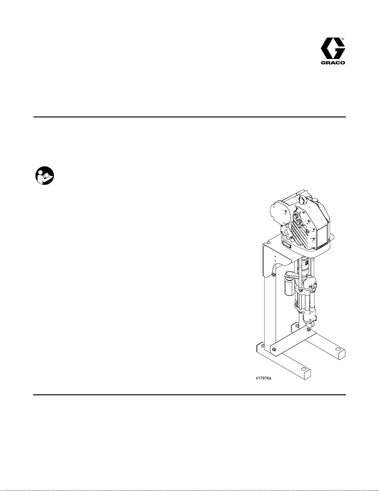
E-Flo®
E-Flo® E-Flo®
Electric
Electric Electric
For
For For
See Technical Data, page 29, for
Maximum Working Pressure.
See page 3 for model part numbers and
approvals information.
drive
drive drive
professional
professional professional
Important
Important Important
Readallwarningsandinstructionsinthismanual.
Save
Save Save
DC
DC DC
piston
piston piston
use
use use
Safety
Safety Safety
these
instructions.
these these
instructions. instructions.
4–Ball
4–Ball 4–Ball
pumps
pumps pumps
only.
only. only.
for
for for
Instructions
Instructions Instructions
Piston
Piston Piston
low
to
low low
medium
to to
medium medium
volume
volume volume
Pumps
Pumps Pumps
paint
circulation
paint paint
circulation circulation
applications.
applications. applications.
EN
3A2096D
PROVENQUALITY.LEADINGTECHNOLOGY.
Page 2

Contents
Contents Contents
Models...............................................................3
RelatedManuals................................................3
Warnings...........................................................4
Installation..........................................................8
Location......................................................8
MountthePump..........................................8
PowerSupplyRequirements.........................8
ConnectthePowerSupply...........................10
Grounding...................................................11
FluidLineAccessories.................................12
FillWithOilBeforeUsingEquipment.............12
FlushBeforeUsingEquipment......................12
ControlModuleAccessory............................12
Operation...........................................................13
Startup........................................................13
Shutdown....................................................13
PressureReliefProcedure............................13
Maintenance......................................................14
PreventiveMaintenanceSchedule................14
ChangetheOil.............................................14
CheckOilLevel...........................................14
BearingPre-Load.........................................14
Flushing......................................................14
Troubleshooting..................................................15
Repair................................................................16
Disassembly................................................16
Reassembly................................................16
ReassembletheCouplingAdapterandTie
RodstotheMotor...........................17
Parts..................................................................18
PumpAssembly...........................................18
PumpMatrix................................................20
Dimensions........................................................22
MountingHolePatterns.......................................23
PerformanceCharts............................................25
TechnicalData...................................................29
GracoStandardWarranty....................................30
2
3A2096D
Page 3
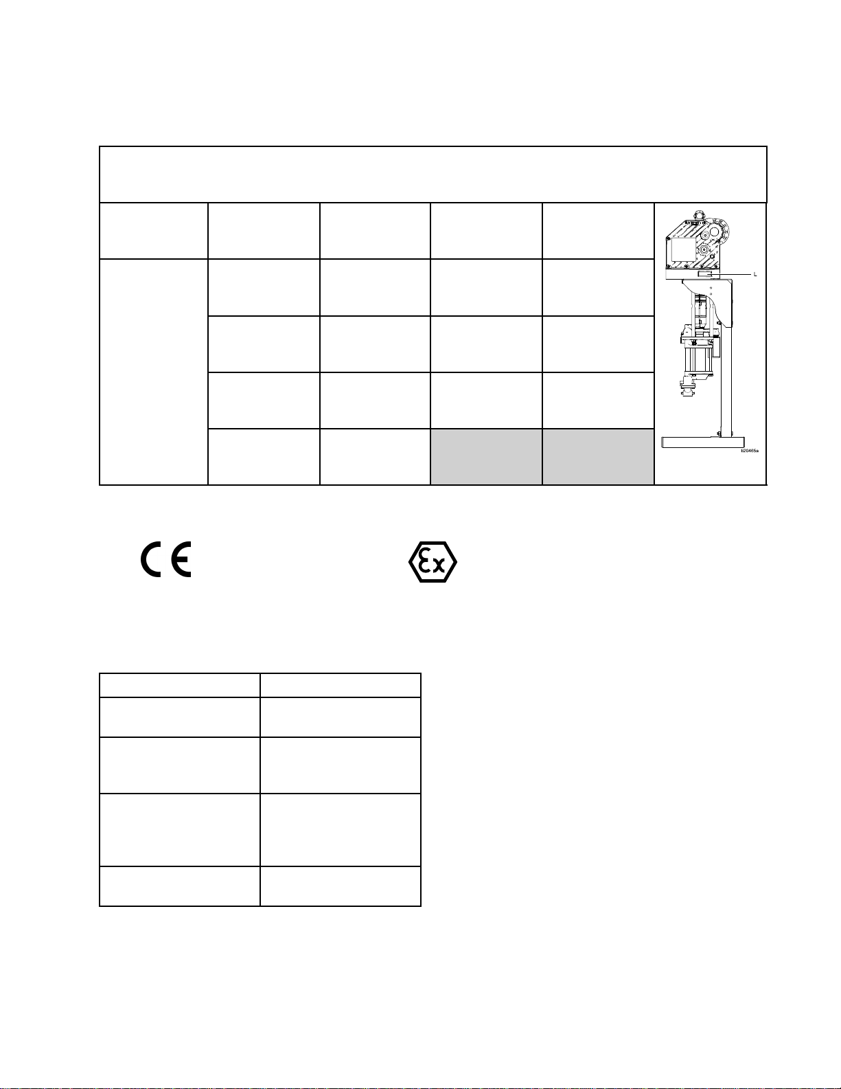
Models
Models
Models Models
The
part
The The
includes
includes includes
See
See See
Flo
E EE- --Flo Flo
number
part part
number number
digits
digits digits
Pump
Pump Pump
DC
Pump
DC DC
Pump Pump
(EC)
(EC) (EC)
for
your
for for
from
from from
Matrix
Matrix Matrix
page
, ,,page page
equipment
your your
equipment equipment
each
each each
Pump
Pump Pump
(1,
(1, (1,
Lower
Lower Lower
2, 2,2,3, 3,3,or or
the
following
of ofofthe the
following following
20
for
20 20
for for
a aacomplete complete
Size
Size Size
or
4)
4) 4)
printed
is isisprinted printed
complete
Motor
Motor Motor
(1,
(1, (1,
Controls
Controls Controls
categories,
categories, categories,
2, 2,2,3, 3,3,or or
on
the
on on
list
list list
of ofofpump pump
and
and and
or
equipment
the the
equipment equipment
depending
depending depending
pump
part
part part
Pump
Pump Pump
and
and and
4)
4) 4)
(1,
(1, (1,
identication
identication identication
on
the
on on
numbers.
numbers. numbers.
Type
Type Type
Fittings
Fittings Fittings
or
2, 2,2,or or
conguration
the the
conguration conguration
3)
3) 3)
label
(L).
The
part
label label
(L). (L).
The The
your
of ofofyour your
Mounting
Mounting Mounting
(0,
(0, (0,
Type
Type Type
or
2)
1, 1,1,or or
2) 2)
number
part part
number number
equipment.
equipment. equipment.
EC
The
following
The The
following following
EC43xx).
EC43xx). EC43xx).
NOTE:
NOTE: NOTE:
Related
Related Related
SeetheE-FloDCMotormanualformotorapprovalsinformation.
1=750cc1=1
2=1000cc2=1
3=1500cc3=2
4=2000cc4=2
approvals
approvals approvals
Manuals
Manuals Manuals
apply
apply apply
to totoBasic Basic
Horsepower,
Basic
Horsepower,
Advanced
Horsepower,
Basic
Horsepower,
Advanced
Basic
models
models models
only
only only
1=Hard
Chrome,
NPT
2=Hard
Chrome,
Tri-Clamp
3=Maxlife,
Tri-Clamp
(Part
Nos.
(Part (Part
EC11xx,
Nos. Nos.
EC11xx, EC11xx,
0=None
1=Stand
2=WallBracket
EC21xx,
EC21xx, EC21xx,
EC23xx,
EC23xx, EC23xx,
EC33xx,
EC33xx, EC33xx,
and
and and
Manual
Manual Manual
3A2526Instructions-Parts
3A2527Instructions-Parts
332013Instructions-Parts
3A0539Instructions-Parts
No.
No. No.
Description
Description Description
Manual,E-FloDCMotor
Manual,forE-FloDC
ControlModuleKit
Manual,forAdvanced
DisplayControlModule
(ADCM)
Manual,4–BallLowers
3A2096D 3
Page 4
Warnings
Warnings
Warnings Warnings
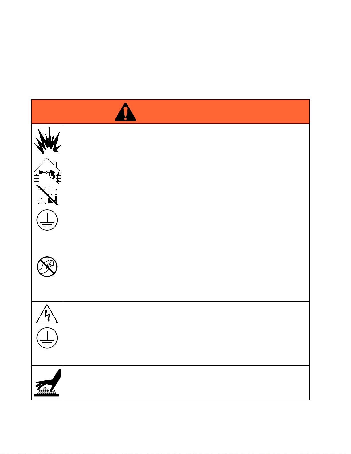
Thefollowingwarningsareforthesetup,use,grounding,maintenance,andrepairofthisequipment.The
exclamationpointsymbolalertsyoutoageneralwarningandthehazardsymbolsrefertoprocedure-specic
risks.Whenthesesymbolsappearinthebodyofthismanualoronwarninglabels,referbacktothese
Warnings.Product-specichazardsymbolsandwarningsnotcoveredinthissectionmayappearthroughout
thebodyofthismanualwhereapplicable.
WARNING
WARNING WARNING
FIRE
AND
FIRE FIRE
Flammablefumes,suchassolventandpaintfumes,inwork work
preventreandexplosion:
•Useequipmentonlyinwellventilatedarea.
•Eliminateallignitionsources;suchaspilotlights,cigarettes,portableelectriclamps,and
plasticdropcloths(potentialstaticarc).
•Keepworkareafreeofdebris,includingsolvent,ragsandgasoline.
•Donotplugorunplugpowercords,orturnpowerorlightswitchesonoroffwhenammable
fumesarepresent.
•Groundallequipmentintheworkarea.SeeGrounding Grounding
•Useonlygroundedhoses.
•Holdgunrmlytosideofgroundedpailwhentriggeringintopail.Donotusepaillinersunless
theyareantistaticorconductive.
Stop
•Stop Stop
equipmentuntilyouidentifyandcorrecttheproblem.
•Keepaworkingreextinguisherintheworkarea.
EXPLOSION
AND AND
EXPLOSION EXPLOSION
operation
operation operation
immediately
immediately immediately
HAZARD
HAZARD HAZARD
work
area
area area
canigniteorexplode.Tohelp
Grounding
ifstaticsparkingoccursoryoufeelashock,Donotuse
instructions.
Staticchargemaybuilduponplasticpartsduringcleaningandcoulddischargeandignite
ammablevapors.Tohelppreventreandexplosion:
•Cleanplasticpartsonlyinwellventilatedarea.
•Donotcleanwithadrycloth.
•Donotoperateelectrostaticgunsinequipmentworkarea.
ELECTRIC
ELECTRIC ELECTRIC
Thisequipmentmustbegrounded.Impropergrounding,setup,orusageofthesystemcan
causeelectricshock.
•Turnoffanddisconnectpoweratmainswitchbeforedisconnectinganycablesandbefore
servicingorinstallingequipment.
•Connectonlytogroundedpowersource.
•Allelectricalwiringmustbedonebyaqualiedelectricianandcomplywithalllocalcodes
andregulations.
BURN
BURN BURN
Equipmentsurfacesanduidthat’sheatedcanbecomeveryhotduringoperation.Toavoid
severeburns:
•Donottouchhotuidorequipment.
SHOCK
SHOCK SHOCK
HAZARD
HAZARD HAZARD
HAZARD
HAZARD HAZARD
4
3A2096D
Page 5
WARNING
WARNING WARNING
MOVING
MOVING MOVING
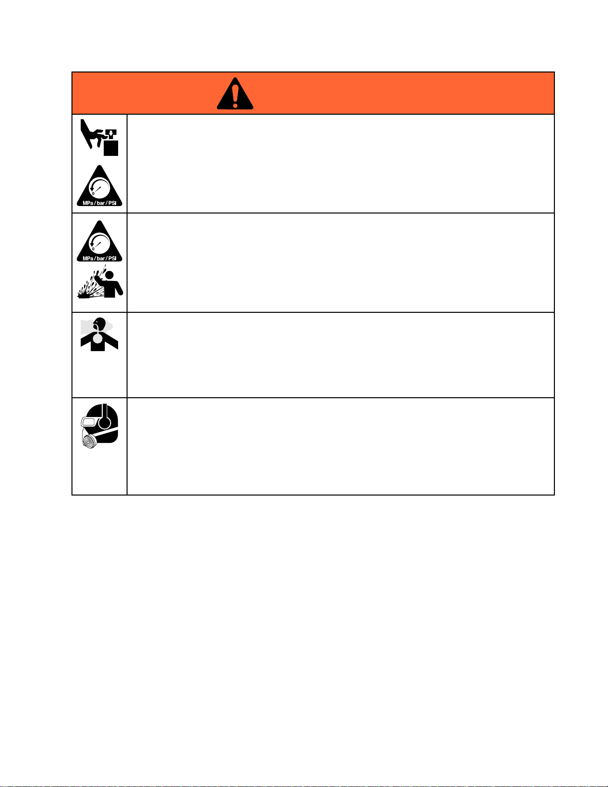
Movingpartscanpinch,cutoramputatengersandotherbodyparts.
•Keepclearofmovingparts.
•Donotoperateequipmentwithprotectiveguardsorcoversremoved.
•Pressurizedequipmentcanstartwithoutwarning.Beforechecking,moving,orservicing
equipment,followthePressure Pressure
PARTS
PARTS PARTS
HAZARD
HAZARD HAZARD
Pressure
Relief
Procedure
Relief Relief
Procedure Procedure
anddisconnectallpowersources.
Warnings
PRESSURIZED
PRESSURIZED PRESSURIZED
Fluidfromtheequipment,leaks,orrupturedcomponentscansplashintheeyesoronskin
andcauseseriousinjury.
•FollowthePressure Pressure
cleaning,checking,orservicingequipment.
•Tightenalluidconnectionsbeforeoperatingtheequipment.
•Checkhoses,tubes,andcouplingsdaily.Replacewornordamagedpartsimmediately.
TOXIC
TOXIC TOXIC
Toxicuidsorfumescancauseseriousinjuryordeathifsplashedintheeyesoronskin,
inhaled,orswallowed.
•ReadMSDSstoknowthespecichazardsoftheuidsyouareusing.
•Storehazardousuidinapprovedcontainers,anddisposeofitaccordingtoapplicable
PERSONAL
PERSONAL PERSONAL
Wearappropriateprotectiveequipmentwhenintheworkareatohelppreventseriousinjury,
includingeyeinjury,hearingloss,inhalationoftoxicfumes,andburns.Thisequipmentincludes
butisnotlimitedto:
•Protectiveeyewear,andhearingprotection.
•Respirators,protectiveclothing,andglovesasrecommendedbytheuidandsolvent
FLUID
FLUID FLUID
guidelines.
manufacturer.
EQUIPMENT
EQUIPMENT EQUIPMENT
Pressure
OR
OR OR
PROTECTIVE
PROTECTIVE PROTECTIVE
Relief
Relief Relief
FUMES
FUMES FUMES
HAZARD
HAZARD HAZARD
Procedure
Procedure Procedure
EQUIPMENT
EQUIPMENT EQUIPMENT
whenyoustopspraying/dispensingandbefore
3A2096D 5
Page 6
Warnings
WARNING
WARNING WARNING
EQUIPMENT
EQUIPMENT EQUIPMENT
Misusecancausedeathorseriousinjury.
•Donotoperatetheunitwhenfatiguedorundertheinuenceofdrugsoralcohol.
•Donotexceedthemaximumworkingpressureortemperatureratingofthelowestrated
systemcomponent.SeeTechnical Technical
•Useuidsandsolventsthatarecompatiblewithequipmentwettedparts.SeeTechnical Technical
inallequipmentmanuals.Readuidandsolventmanufacturer’swarnings.Forcomplete
informationaboutyourmaterial,requestMSDSfromdistributororretailer.
•Donotleavetheworkareawhileequipmentisenergizedorunderpressure.
•TurnoffallequipmentandfollowthePressure Pressure
•Checkequipmentdaily.Repairorreplacewornordamagedpartsimmediatelywithgenuine
manufacturer’sreplacementpartsonly.
•Donotalterormodifyequipment.Alterationsormodicationsmayvoidagencyapprovals
andcreatesafetyhazards.
•Makesureallequipmentisratedandapprovedfortheenvironmentinwhichyouareusingit.
•Useequipmentonlyforitsintendedpurpose.Callyourdistributorforinformation.
•Routehosesandcablesawayfromtrafcareas,sharpedges,movingparts,andhotsurfaces.
•Donotkinkoroverbendhosesorusehosestopullequipment.
•Keepchildrenandanimalsawayfromworkarea.
•Complywithallapplicablesafetyregulations.
MISUSE
MISUSE MISUSE
HAZARD
HAZARD HAZARD
Technical
Data
Data Data
Pressure
inallequipmentmanuals.
Relief
Relief Relief
Technical
Procedure
Procedure Procedure
whenequipmentisnotinuse.
Data
Data Data
6 3A2096D
Page 7

Notes
Notes
Notes Notes
3A2096D
7
Page 8
Installation
Installation
Installation Installation
Installationofthisequipmentinvolvespotentially
hazardousprocedures.Onlytrainedandqualied
personnelwhohavereadandwhounderstand
theinformationinthismanualshouldinstallthis
equipment.
Location
Location Location
Whenselectingthelocationfortheequipment,keep
thefollowinginmind:
•Theremustbesufcientspaceonallsidesof
theequipmentforinstallation,operatoraccess,
maintenance,andaircirculation.
•Ensurethatthemountingsurfaceandmounting
hardwarearestrongenoughtosupporttheweight
oftheequipment,uid,hoses,andstresscaused
duringoperation.
•Theremustbeastart/stopcontrol(C)withineasy
reachoftheequipment.SeeFig.1.
Mount
Mount Mount
the
Pump
the the
Pump Pump
Power
Power Power
Improperwiringmaycauseelectricshockorother
seriousinjuryifworkisnotperformedproperly.
Haveaqualiedelectricianperformanyelectrical
work.Besureyourinstallationcomplieswithall
National,StateandLocalsafetyandrecodes.
SeeTable1forpowersupplyrequirements.The
systemrequiresadedicatedcircuitprotectedwitha
circuitbreaker.
Table
Table Table
Model
Model Model
EM0011
EM0012
EM0021
EM0022
Hazardous
Hazardous Hazardous
Requirements
Requirements Requirements
Supply
Supply Supply
Power
1 11. ..Power Power
Voltage
Voltage Voltage
100–250
Vac
200–250
Vac
Requirements
Requirements Requirements
Supply
Supply Supply
Area
Area Area
Specications
Specications Specications
Phase
Phase Phase
150/6020A
150/6020A
Cabling
Cabling Cabling
and
and and
Hz
Hz Hz
Conduit
Conduit Conduit
Current
Current Current
SeeMountingHolePatterns,page23.
SecurethestandtotheoorwithM19(5/8in.)
boltswhichengageatleast152mm(6in.)intothe
concreteoortopreventthepumpfromtipping.
Levelthepumpasrequired,usingshims.
Explosion
Explosion Explosion
Allelectricalwiringinthehazardousareamustbe
encasedinClassI,DivisionI,GroupDapproved
explosion-proofconduit.FollowallNational,State,
andLocalelectriccodes.
Aconduitseal(D)isrequiredwithin18in.(457mm)
ofthemotorfortheUSandCanada.SeeFig.3.
Allcablesmustberatedat70°C(158°F).
Flame
Flame Flame
Useappropriateconduit,connectors,andcable
glandsratedforATEXII2G.FollowallNational,
State,andLocalelectriccodes.
Allcableglandsandcablesmustberatedat70°C
(158°F).
Proof
Proof Proof
Proof
Proof Proof
(ATEX)
(ATEX) (ATEX)
8 3A2096D
Page 9
Installation
NON
HAZARDOUS
NON NON
- --HAZARDOUS HAZARDOUS
AREA
AREA AREA
HAZARDOUS
HAZARDOUS HAZARDOUS
AREA
AREA AREA
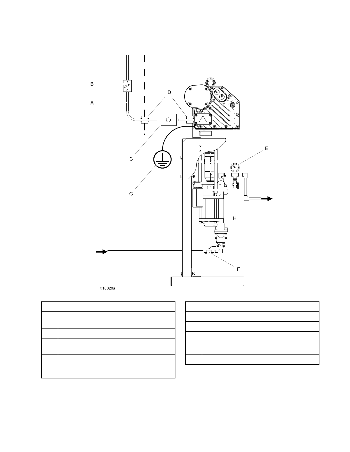
Figure1TypicalInstallation
Key
for
Fig.
Key Key
for for
A
B
CStart/StopControl(mustbeapprovedfor
D
1
Fig. Fig.
1 1
ElectricalSupply(mustbesealedconduit
approvedforuseinhazardouslocations)
FusedSafetySwitch,withlock
useinhazardouslocations)
ExplosionProofConduitSeal.Required
within18in.(457mm)ofthemotorforthe
USandCanada.
Key
for
Fig.
Key Key
for for
E
F
GPumpGroundWire.Twogroundterminals
HFluidDrainValve
1
Fig. Fig.
1 1
FluidPressureGauge
FluidShutoffValve
areprovidediflocalcoderequiresredundant
groundingconnections.
3A2096D 9
Page 10
Installation
Connect
Connect Connect
Improperwiringmaycauseelectricshockorother
seriousinjuryifworkisnotperformedproperly.
Haveaqualiedelectricianperformanyelectrical
work.Besureyourinstallationcomplieswithall
National,StateandLocalsafetyandrecodes.
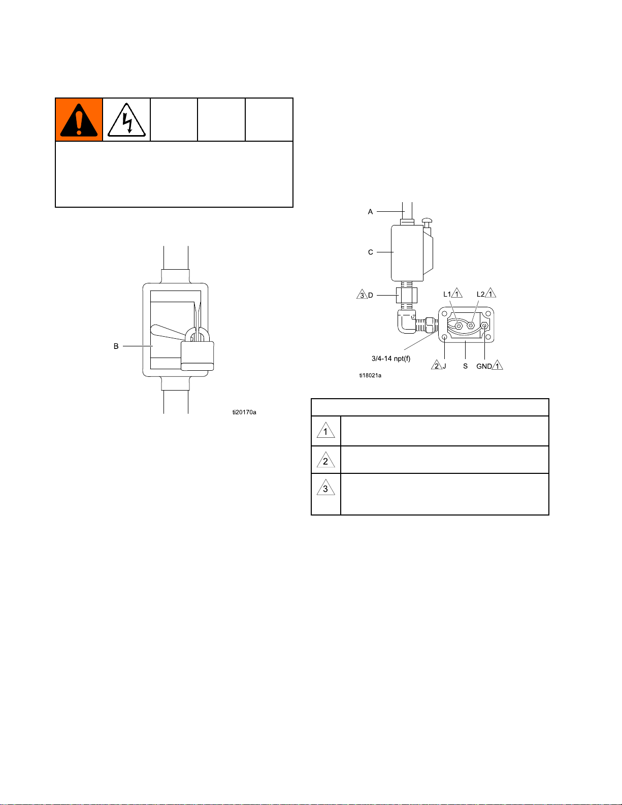
1.Ensurethatthefusedsafetyswitch(B,Fig2)is
shutoffandlockedout.
the
Power
the the
Power Power
Supply
Supply Supply
3.Opentheelectricalcompartment(S)onthe
motor.
4.Bringthepowerwiresintotheelectrical
compartmentthroughthe3/4–14npt(f)inletport.
Connectthewirestotheterminals,asshown.
Torquetheterminalnutsto25in-lb(2.8N•m)
Do
not
maximum.Do Do
5.Closetheelectricalcompartment.Torquethe
coverscrewsto15ft-lb(20.3N•m).
over-torque.
not not
over-torque. over-torque.
Figure2LockedOutFusedSafetySwitch
2.SeeFig.3.Installastart/stopcontrol(C)inthe
electricalsupplyline(A),withineasyreachof
theequipment.Thestart/stopcontrolmustbe
approvedforuseinhazardouslocations.
Figure3ConnectthePowerWires
Notes
for
Fig.
Notes Notes
for for
Tightenallterminalnutsto25in-lb(2.8N•m)
maximum.Do Do
Tightencoverscrewsto15ft-lb(20.3N•m).
Aconduitseal(D)isrequiredwithin18
in.(457mm)ofthemotorfortheUSand
Canada.
3
Fig. Fig.
3 3
Do
not
over
not not
torque.
over over
- --torque. torque.
10 3A2096D
Page 11

Grounding
Grounding Grounding
Thisequipmentmustbegroundedtoreducethe
riskofstaticsparkingandelectricshock.Electric
orstaticsparkingcancausefumestoigniteor
explode.Impropergroundingcancauseelectric
shock.Groundingprovidesanescapewireforthe
electriccurrent.
Pump:
1.Pump: Pump:
attachagroundwire.Tightenthegroundscrew
securely.Connecttheotherendoftheground
wiretoatrueearthground.
NOTE:
NOTE: NOTE:
ofthe24P822ControlModule.Allpumps
connectedtoacommoncontrolmodulemustbe
groundedtothesamegroundpoint.Different
groundpoints(unequalpotential)maycause
currenttoowthroughcomponentcables,
causingincorrectsignals.
SeeFig.4.Loosenthegroundscrewand
Advancedmodelsrequireinstallation
Figure4GroundWire
Fluid
2.Fluid Fluid
3.Fluid Fluid
hoses:
hoses: hoses:
hoseswithamaximumof500ft.(150m)
combinedhoselengthtoensuregrounding
continuity.Checktheelectricalresistanceof
hoses.Iftotalresistancetogroundexceeds25
megohms,replacehoseimmediately
Fluid
supply
supply supply
Useonlyelectricallyconductive
container:
container: container:
Followyourlocalcode.
Installation
3A2096D
11
Page 12
Installation
Fluid
Fluid Fluid
Installthefollowingaccessoriesintheordershown
inFig.1,usingadaptersasnecessary.Alluid
linesandaccessoriesmustberatedtothemaximum
workingpressureof400psi(2.8MPa,28.0bar).
•Fluid Fluid
•Fluid Fluid
•Fluid Fluid
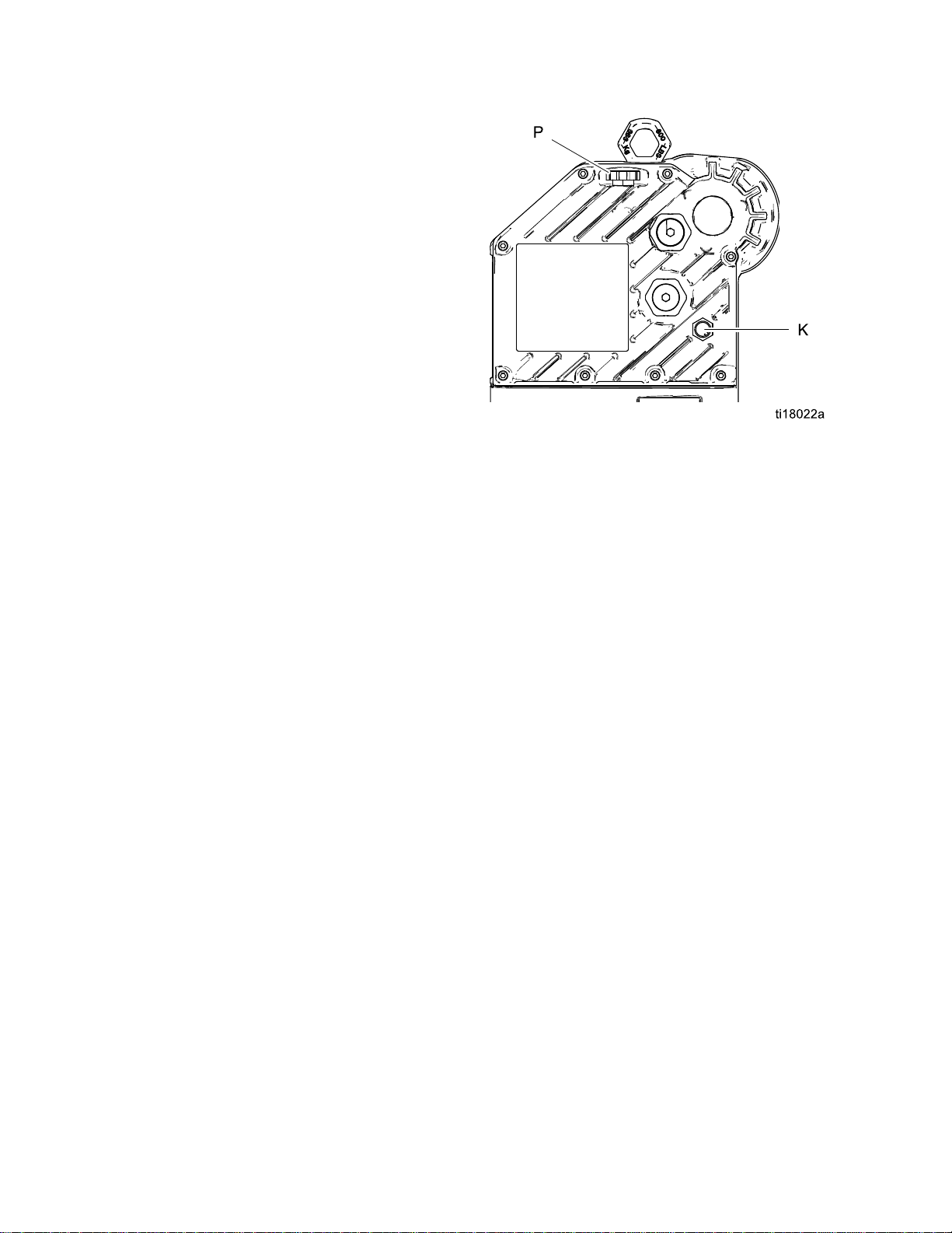
Fill
Fill Fill
SeeFig.5.Beforeusingtheequipment,openthell
cap(P)andaddGracoPartNo.16W645ISO220
silicone-freesyntheticgearoil.Checktheoillevelin
thesightglass(K).Filluntiltheoillevelisnearthe
halfwaypointofthesightglass.Theoilcapacityis
approximately1.5quarts(1.4liters).Do Do
NOTE:
NOTE: NOTE:
suppliedwiththeequipment.
Line
Line Line
Fluid
drain
drain drain
relieveuidpressureinthehoseandcirculation
system.
Fluid
pressure pressure
adjustmentoftheuidpressure.
Fluid
shutoff
shutoff shutoff
With
With With
Two1quart(0.95liter)bottlesofoilare
Accessories
Accessories Accessories
valve
(D):
valve valve
(D): (D):
requiredinyoursystem,to
pressure
gauge
gauge gauge
valve
valve valve
Oil
Before
Oil Oil
Before Before
(F):
(F): (F):
(E):
(E): (E):
shutsoffuidow.
Using
Using Using
formoreprecise
Equipment
Equipment Equipment
Do
not
overll.
not not
overll. overll.
Figure5SightglassandOilFillCap
Flush
Flush Flush
Thepumpuidsectionwastestedwithlightweight
oil,whichisleftintheuidpassagestoprotectparts.
Toavoidcontaminatingyouruidwithoil,ushthe
equipmentwithacompatiblesolventbeforeusing
theequipment.
Before
Before Before
Using
Using Using
Equipment
Equipment Equipment
Control
Control Control
TheControlModuleAccessoryisrequiredwith
AdvancedE-FloDCmotorstoprovidetheinterface
foruserstoenterselectionsandviewinformation
relatedtosetupandoperation.SeetheControl
ModuleAccessoryKitmanualforinstallationand
operationinformation.
Module
Module Module
Accessory
Accessory Accessory
12
3A2096D
Page 13

Operation
Operation
Operation Operation
Startup
Startup Startup
Tooperatethepump,followtheStartupinstructions
fortheBasicorAdvancedmotorintheMotormanual.
TheAdvancedE-FloDCmotorsrequireinstallationof
the24P822ControlModuleAccessoryKittoprovide
theinterfaceforuserstoenterselectionsandview
informationrelatedtosetupandoperation.Seethe
ControlModuleAccessoryKitmanualforinstallation
andoperationinformation.
Runthepumpataslowspeeduntiltheuidlinesare
primedandallairisforcedoutofthesystem.
Shutdown
Shutdown Shutdown
FollowthePressureReliefProcedure,page13.
Pressure
Pressure Pressure
Thisequipmentstayspressurizeduntilpressureis
manuallyrelieved.Tohelppreventseriousinjury
fromsplashinguidandmovingparts,followthe
PressureReliefProcedurewhenyoustopspraying
andbeforecleaning,checking,orservicingthe
equipment.
1.Disengagethestart/stopcontrol(C).SeeFig.1.
2.Shutoffandlockoutthefusedsafetyswitch(B).
3.Opentheuiddrainvalve(D),havingawaste
containerreadytocatchdrainage.Leaveopen
untilyouarereadytopressurizesystemagain.
Relief
Relief Relief
Procedure
Procedure Procedure
3A2096D 13
Page 14
Maintenance
Maintenance
Maintenance Maintenance
Preventive
Preventive Preventive
Theoperatingconditionsofyourparticularsystem
determinehowoftenmaintenanceisrequired.
Establishapreventivemaintenancescheduleby
recordingwhenandwhatkindofmaintenanceis
needed,andthendeterminearegularschedulefor
checkingyoursystem.
Change
Change Change
NOTE:
NOTE: NOTE:
200,000–300,000cycles.Afterthebreak-inperiod,
changetheoilonceayear.
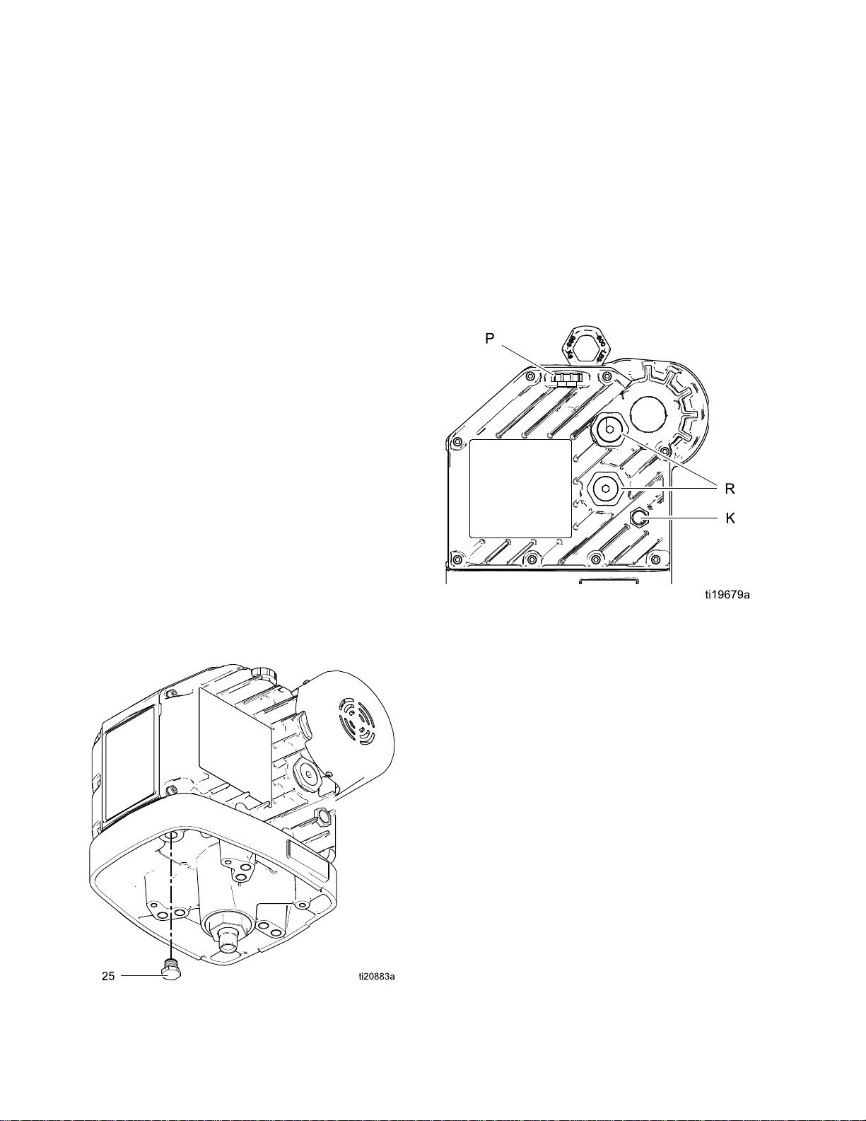
1.SeeFig.6.Placeaminimum2quart(1.9liter)
2.Reinstalltheoildrainplug(25).Torqueto25–30
3.SeeFig.7.Openthellcap(P)andaddGraco
Changetheoilafterabreak-inperiodof
containerundertheoildrainport.Removethe
oildrainplug(25).Allowalloiltodrainfromthe
motor.
ft-lb(34–40N•m).
PartNo.16W645ISO220silicone-freesynthetic
gearoil.Checktheoillevelinthesightglass(K).
Filluntiltheoillevelisnearthehalfwaypointof
thesightglass.Theoilcapacityisapproximately
1.5quarts(1.4liters).Do Do
Maintenance
Maintenance Maintenance
the
Oil
the the
Oil Oil
Do
Schedule
Schedule Schedule
not
overll.
not not
overll. overll.
Check
Check Check
SeeFig.7.Checktheoillevelinthesightglass(K).
Theoillevelshouldbenearthehalfwaypointofthe
sightglasswhentheunitisnotrunning.Iflow,open
thellcap(P)andaddGracoPartNo.16W645ISO
220silicone-freesyntheticgearoilasrequired.The
oilcapacityisapproximately1.5quarts(1.4liters).
Do
Do Do
Figure7SightglassandOilFillCap
Oil
Level
Oil Oil
Level Level
not
overll.
not not
overll. overll.
4.Reinstallthellcap.
Figure6OilDrainPlug
Bearing
Bearing Bearing
SeeFig.7.Thebearingpre-loads(R)arefactory
setandarenotuseradjustable.Donotadjustthe
bearingpre-loads.
Flushing
Flushing Flushing
•Flushbeforechanginguids,beforeuidcandry
intheequipment,attheendoftheday,before
storing,andbeforerepairingequipment.
•Flushatthelowestpressurepossible.Check
connectorsforleaksandtightenasnecessary.
•Flushwithauidthatiscompatiblewiththeuid
beingdispensedandtheequipmentwettedparts.
Pre
Load
Pre Pre
- --Load Load
14
3A2096D
Page 15

Troubleshooting
Troubleshooting
Troubleshooting Troubleshooting
NOTE:
NOTE: NOTE:
Checkallpossibleremediesbeforedisassemblingthepump.
NOTE:
NOTE: NOTE:
manualforfurtherinformation.
TheLEDonthemotorwillblinkifanerrorisdetected.SeeError Error
Problem
Problem Problem
Pumpoutputlowonbothstrokes.
Pumpoutputlowononlyone
stroke.
Nooutput.Improperlyinstalledballcheck
Pumpoperateserratically.
Pumpwillnotoperate.
Cause
Cause Cause
Inadequatepowersupply.
Exhausteduidsupply.Rellandreprimepump.
Cloggeduidoutletline,valves,
etc.
Wornpistonpacking.
Heldopenorwornballcheck
valves.
Wornpistonpacking.
valves.
Exhausteduidsupply.Rellandreprimepump.
Heldopenorwornballcheck
valves.
Wornpistonpacking.
Inadequatepowersupply.
Error
Code
Troubleshooting
Code Code
Troubleshooting Troubleshooting
Solution
Solution Solution
SeePowerSupplyRequirements,
page8.
Clear.
Replace.Seelowermanual.
Checkandrepair.Seelower
manual.
Replace.Seelowermanual.
Checkandrepair.Seelower
manual.
Checkandrepair.Seelower
manual.
Replace.Seelowermanual.
SeePowerSupplyRequirements,
page8.
inthemotor
Exhausteduidsupply.Rellandreprimepump.
Cloggeduidoutletline,valves,
etc.
Fluiddriedonpistonrod.Disassembleandcleanpump.
Clear.
Seelowermanual.Infuture,stop
pumpatbottomofstroke.
3A2096D 15
Page 16

Repair
Repair
Repair Repair
Disassembly
Disassembly Disassembly
1.Stopthepumpatthebottomofitsstroke.
2.Relievethepressure.Seethe
PressureReliefProcedure,page13.
3.Disconnectthehosesfromthelowerandplug
theendstopreventuidcontamination.
4.Removethe2-pieceshield(12)byinsertinga
screwdriverstraightintotheslot,andusingitas
alevertoreleasethetab.Repeatforalltabs.Do Do
not
not not
usethescrewdrivertoprytheshieldsapart.
Reassembly
Reassembly Reassembly
NOTE:
NOTE: NOTE:
(6)havebeendisassembledfromthemotor,see
ReassembletheCouplingAdapterandTieRodsto
theMotor,page17.
1.SeeFig.8.Assemblethecouplingnut(11)to
2.Orientthelower(7)tothemotor(3).Positionthe
3.Insertthecollars(10)intothecouplingnut
Do
4.Installtheshields(12)byengagingthebottom
Ifthecouplingadapter(9)andtierods
thepistonrod(R).
loweronthetierods(6).Lubricatethethreadsof
thetierods.Screwthetierodlocknuts(8)onto
thetierods.Tightenthelocknutsandtorqueto
50-60ft-lb(68-81N•m).
(11).Tightenthecouplingnutontothecoupling
adapter(9)andtorqueto90–100ft-lb(122–135
N•m).
lipswiththegrooveinthewet-cupcap.Snapthe
twoshieldstogether.
5.Loosenthecouplingnut(11)andremovethe
collars(10).Removethecouplingnutfromthe
pistonrod(R).Unscrewthelocknuts(8)fromthe
tierods(6).Separatethemotor(3)andlower
(7).SeeFig.7.
6.Torepairthelower,seethelowermanual.
7.Therearenouser-serviceablepartsinthe
motor.ContactyourGracorepresentativefor
assistance.
16 3A2096D
5.Flushandtestthepumpbeforereinstalling
itinthesystem.Connecthosesandush
thepump.Whileitispressurized,checkfor
smoothoperationandleaks.Adjustorrepair
asnecessarybeforereinstallinginthesystem.
Reconnectthepumpgroundwirebefore
operating.
Page 17

Repair
Reassemble
Reassemble Reassemble
NOTE:
NOTE: NOTE:
adapter(9)andtierods(6)havebeendisassembled
fromthemotor,toensureproperalignmentofthe
motorshafttothepistonrod(R).
1.SeeFig.7.Screwthetierods(6)intothemotor
Usethisprocedureonlyifthecoupling
(3)andtorqueto50-60ft-lb(68-81N•m).
the
Coupling
the the
Coupling Coupling
Adapter
Adapter Adapter
and
Tie
and and
Rods
Tie Tie
Rods Rods
2.Screwthecouplingadapter(9)intothemotor
shaftandtorqueto90–100ft-lb(122–135N•m).
3.Reassemblethepumptothemotor,asexplained
inReassembly,page16.
to
the
to to
Motor
the the
Motor Motor
Figure8PumpAssembly
3A2096D
Notes
for
Fig.
Notes Notes
for for
Torqueto50–60ft-lb(68–81N•m).
Torqueto90–100ft-lb(122–135N•m).
8
Fig. Fig.
8 8
17
Page 18

Parts
Parts
Parts Parts
Pump
Pump Pump
SeeModels,page3foranexplanationofthepumppartnumber.
Assembly
Assembly Assembly
18 3A2096D
Page 19

Parts
Ref
Ref Ref
1
2
3
3a▲16M130LABEL,warning1
3b16W645
4
5
6
7
8108683NUT,lock,hex3
915H369ADAPTER1
10184128
11184059NUT,coupling1
1224F251
▲ReplacementDangerandWarninglabels,tags,
andcardsareavailableatnocost.
Part
Part Part
SeePumpMatrix,page20
SeePumpMatrix,page20STAND,oor
SeePumpMatrix,page20MOTOR;BasicorAdvanced;seemotor
SeePumpMatrix,page20WASHER
SeePumpMatrix,page20BOLT
15G924ROD,tie
SeePumpMatrix,page20
Description
Description Description
KIT,mountingbracket,pump;includesitems
4and5;seemanual311619
manual;includesitems3aand3b
OIL,gear,synthetic;ISO220silicone-free;
1quart(0.95liter);notshown
PUMP,displacement;seelowermanual1
COLLAR,coupling
KIT,shield,coupler(includes2pieces)
Qty
Qty Qty
1
1
1
2
4
4
3
2
1
3A2096D 19
Page 20

Parts
Pump
Pump Pump
Pump
Pump Pump
Part
Part Part
EC1110
EC1111
EC1112
EC1210
EC1211
EC1212
EC2110
EC2111
EC2112
EC2210
EC2211
EC2212
EC2310
Matrix
Matrix Matrix
Pump
Pump Pump
No.
No. No.
Series
Series Series
AEM001124F413
A255143256193EM001110013310010124F413
A255143EM001110013310010124F413
AEM001224F413
A255143256193EM001210013310010124F413
A255143EM001210013310010124F413
AEM001124F424
A255143256193EM001110013310010124F424
A255143EM001110013310010124F424
AEM001224F424
A255143256193EM001210013310010124F424
A255143EM001210013310010124F424
AEM002124F424
Mounting
Mounting Mounting
Bracket
Bracket Bracket
(Ref
1)
(Ref (Ref
1) 1)
Floor
Stand
Floor Floor
Stand Stand
(Ref
2)
(Ref (Ref
2) 2)
Motor
Motor Motor
(Ref
3)
(Ref (Ref
3) 3)
Washer
Washer Washer
(Ref
4)
(Ref (Ref
4) 4)
Bolt
Bolt Bolt
(Ref
5)
(Ref (Ref
5) 5)
Lower
Lower Lower
Pump
Pump Pump
(Ref
7)
(Ref (Ref
7) 7)
EC2311
EC2312
EC2410
EC2411
EC2412
EC2320
EC2321
EC2322
EC2420
EC2421
EC2422
EC2330
EC2331
EC2332
EC2430
EC2431
EC2432
A255143256193EM002110013310010124F424
A255143EM002110013310010124F424
AEM002224F424
A255143256193EM002210013310010124F424
A255143EM002210013310010124F424
AEM002124F426
A255143256193EM002110013310010124F426
A255143EM002110013310010124F426
AEM002224F426
A255143256193EM002210013310010124F426
A255143EM002210013310010124F426
AEM002124F427
A255143256193EM002110013310010124F427
A255143EM002110013310010124F427
AEM002224F427
A255143256193EM002210013310010124F427
A255143EM002210013310010124F427
EC3310
EC3311
EC3312
AEM002124F432
A255143256193EM002110013310010124F432
A255143EM002110013310010124F432
20 3A2096D
Page 21

Parts
Pump
Pump Pump
Part
No.
Part Part
No. No.
EC3410
EC3411
EC3412
EC3320
EC3321
EC3322
EC3420
EC3421
EC3422
EC3330
EC3331
EC3332
EC3430
EC3431
EC3432
Pump
Pump Pump
Series
Series Series
AEM002224F432
A255143256193EM002210013310010124F432
A255143EM002210013310010124F432
AEM002124F434
A255143256193EM002110013310010124F434
A255143EM002110013310010124F434
AEM002224F434
A255143256193EM002210013310010124F434
A255143EM002210013310010124F434
AEM002124F435
A255143256193EM002110013310010124F435
A255143EM002110013310010124F435
AEM002224F435
A255143256193EM002210013310010124F435
A255143EM002210013310010124F435
Mounting
Mounting Mounting
Bracket
Bracket Bracket
(Ref
1)
(Ref (Ref
1) 1)
Floor
Stand
Floor Floor
Stand Stand
(Ref
2)
(Ref (Ref
2) 2)
Motor
Motor Motor
(Ref
3)
(Ref (Ref
3) 3)
Washer
Washer Washer
(Ref
4)
(Ref (Ref
4) 4)
Bolt
Bolt Bolt
(Ref
5)
(Ref (Ref
5) 5)
Lower
Lower Lower
Pump
Pump Pump
(Ref
7)
(Ref (Ref
7) 7)
EC4310
EC4311
EC4312
EC4410
EC4411
EC4412
EC4320
EC4321
EC4322
EC4420
EC4421
EC4422
EC4330
EC4331
EC4332
EC4430
EC4431
AEM002124F440
A255143256193EM002110013310010124F440
A255143EM002110013310010124F440
AEM002224F440
A255143256193EM002210013310010124F440
A255143EM002210013310010124F440
AEM002124F441
A255143256193EM002110013310010124F441
A255143EM002110013310010124F441
AEM002224F441
A255143256193EM002210013310010124F441
A255143EM002210013310010124F441
AEM002124F442
A255143256193EM002110013310010124F442
A255143EM002110013310010124F442
AEM002224F442
A255143256193EM002210013310010124F442
EC4432
3A2096D
A255143EM002210013310010124F442
21
Page 22

Dimensions
Dimensions
Dimensions Dimensions
A
A A
58.00in.(1473mm)17.00in.(432mm)45.50in.(1156mm)19.88in.(505mm)
22
B
B B
C
C C
D
D D
3A2096D
Page 23

MountingHolePatterns
Mounting
Mounting Mounting
Floor
Stand
Floor Floor
Stand Stand
Hole
Hole Hole
Patterns
Patterns Patterns
Dimension
Dimension Dimension
A
B
C16.88in.(429mm)
D
Measurement
Measurement Measurement
19.88in.(505mm)
14.50in.(368mm)
17.00in.(432mm)
3A2096D 23
Page 24

MountingHolePatterns
Pump
Pump Pump
Bracket
Bracket Bracket
Dimension
Dimension Dimension
A
B
C12.4in.(314mm)
D
E
F
G5.3in.(133mm)
H
J
K
L
M
N
P
Measurement
Measurement Measurement
17.8in.(451mm)
14.5in.(368mm)
9.0in.(229mm)
5.4in.(137mm)
7.4in.(187mm)
2.0in.(51mm)
1.0in.(25mm)
1.6in.(41mm)
2.7in.(69mm)
4.4in.(112mm)
Four0.562in.(14mm)diameterholesformountingtostand
Four0.438in.(11mm)diameterholesformountingtowall
24
3A2096D
Page 25

PerformanceCharts
Performance
Performance Performance
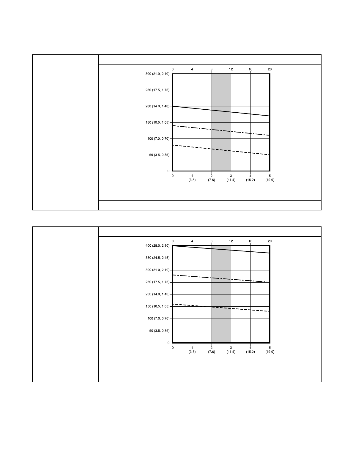
Tondtheuidpressure(psi/bar/MPa)ataspecic
uidow(gpm/lpm)andpercentageofmaximum
force:
1.Locatethedesireduidowinthescaleatthe
bottomofthechart.
2.Followtheverticallineuptotheintersectionwith
theselectedpercentageofmaximumforce(see
Key
theKey Key
3.Followlefttotheverticalscaletoreadtheuid
outletpressure.
Table
Table Table
below).
Models
2 22. ..Models Models
EC11xx
EC11xx EC11xx
Charts
Charts Charts
and
EC12xx
and and
EC12xx EC12xx
(750
(750 (750
Key
Key Key
NOTE:
NOTE: NOTE:
100%,70%,and40%ofmaximumforce.These
valuesareapproximatelyequivalenttoanairmotor
operatingat100,70,and40psi.
cc
lower,
cc cc
lower, lower,
HP
1 11HP HP
Performance
to totoPerformance Performance
Thechartsshowthemotoroperatingat
100%ofmaximumforce
70%ofmaximumforce
40%ofmaximumforce
motor,
motor, motor,
CYCLES
CYCLES CYCLES
1400
1400 1400
PER
MINUTE
PER PER
MINUTE MINUTE
Charts
Charts Charts
maximum
lb lblbmaximum maximum
force)
force) force)
FLUID
PRESSURE:
FLUID FLUID
PRESSURE: PRESSURE:
psi(bar,MPa)
NOTE:
NOTE: NOTE:
Theshadedareawithinthetableshowstherecommendedrangeforcontinuousdutycirculation
applications.
FLUID
FLOW:
FLUID FLUID
FLOW: FLOW:
gpm(lpm)
3A2096D 25
Page 26
PerformanceCharts
Table
Table Table
Table
Table Table
Models
3 33. ..Models Models
FLUID
PRESSURE:
FLUID FLUID
PRESSURE: PRESSURE:
psi(bar,MPa)
Models
4 44. ..Models Models
EC21xx
EC21xx EC21xx
EC23xx
EC23xx EC23xx
and
EC22xx
and and
EC22xx EC22xx
NOTE:
NOTE: NOTE:
applications.
and
EC24xx
and and
EC24xx EC24xx
(1000
cc
(1000 (1000
Theshadedareawithinthetableshowstherecommendedrangeforcontinuousdutycirculation
(1000
(1000 (1000
lower,
cc cc
lower, lower,
cc
lower,
cc cc
lower, lower,
HP
motor,
1 11HP HP
motor, motor,
CYCLES
CYCLES CYCLES
FLUID
FLUID FLUID
HP
motor,
2 22HP HP
motor, motor,
1400
1400 1400
PER
PER PER
FLOW:
FLOW: FLOW:
2800
2800 2800
maximum
lb lblbmaximum maximum
MINUTE
MINUTE MINUTE
gpm(lpm)
maximum
lb lblbmaximum maximum
force)
force) force)
force)
force) force)
CYCLES
CYCLES CYCLES
FLUID
PRESSURE:
FLUID FLUID
PRESSURE: PRESSURE:
psi(bar,MPa)
NOTE:
NOTE: NOTE:
Theshadedareawithinthetableshowstherecommendedrangeforcontinuousdutycirculation
applications.
FLUID
FLUID FLUID
PER
MINUTE
PER PER
MINUTE MINUTE
FLOW:
FLOW: FLOW:
gpm(lpm)
26 3A2096D
Page 27

PerformanceCharts
Table
Table Table
Table
Table Table
Models
5 55. ..Models Models
FLUID
PRESSURE:
FLUID FLUID
PRESSURE: PRESSURE:
psi(bar,MPa)
Models
6 66. ..Models Models
EC33xx
EC33xx EC33xx
EC43xx
EC43xx EC43xx
and
EC34xx
and and
EC34xx EC34xx
NOTE:
NOTE: NOTE:
applications.
and
EC44xx
and and
EC44xx EC44xx
(1500
cc
(1500 (1500
Theshadedareawithinthetableshowstherecommendedrangeforcontinuousdutycirculation
(2000
(2000 (2000
lower,
cc cc
lower, lower,
cc
lower,
cc cc
lower, lower,
HP
motor,
2 22HP HP
motor, motor,
CYCLES
CYCLES CYCLES
FLUID
FLUID FLUID
HP
motor,
2 22HP HP
motor, motor,
2800
2800 2800
PER
PER PER
FLOW:
FLOW: FLOW:
2800
2800 2800
maximum
lb lblbmaximum maximum
MINUTE
MINUTE MINUTE
gpm(lpm)
maximum
lb lblbmaximum maximum
force)
force) force)
force)
force) force)
CYCLES
CYCLES CYCLES
FLUID
PRESSURE:
FLUID FLUID
PRESSURE: PRESSURE:
psi(bar,MPa)
NOTE:
NOTE: NOTE:
Theshadedareawithinthetableshowstherecommendedrangeforcontinuousdutycirculation
applications.
FLUID
FLUID FLUID
PER
MINUTE
PER PER
MINUTE MINUTE
FLOW:
FLOW: FLOW:
gpm(lpm)
3A2096D
27
Page 28

Notes
Notes
Notes Notes
28 3A2096D
Page 29

TechnicalData
Technical
Technical Technical
Flo
DC
E EE- --Flo Flo
Maximum
Maximum Maximum
pressure:
pressure: pressure:
Maximum
Maximum Maximum
pressure:
pressure: pressure:
Maximumcontinuous
cyclerate
MaximumFlow
Input
Input Input
Inputcurrent20Amaximum
Powerinletportsize
Ambienttemperature
range
SounddataLessthan70dB(A)
Oilcapacity
OilspecicationGracoPartNo.16W645ISO220silicone-freesyntheticgearoil
Weight
Fluidinletsize
Fluidoutletsize
Wettedparts
Pumps
DC DC
Pumps Pumps
uid
uid uid
ModelsEC11xxand
ModelsEC21xxand
ModelsEC23xxand
ModelsEC33xxand
ModelsEC43xxand
potential
potential potential
ModelsECx1xxand
ModelsECx3xxand
voltage:
voltage: voltage:
ModelsECx1xxand
ModelsECx3xxand
Data
Data Data
U.S.
U.S. U.S.
working
working working
300psi2.07MPa,20.7bar
EC12xx
200psi1.38MPa,13.8bar
EC22xx
400psi2.76MPa,27.6bar
EC24xx
300psi2.07MPa,20.7bar
EC34xx
220psi1.52MPa,15.2bar
EC44xx
uid
uid uid
218000/v(volumeoflowerincc)=psi1500/v(volumeoflowerincc)=bar
ECx2xx
436000/v(volumeoflowerincc)=psi3000/v(volumeoflowerincc)=bar
ECx4xx
20cpm
Maximumowisdeterminedbythesizeofthepumplower.
SeePerformanceCharts,page25.
100–250Vac,singlephase,50/60Hz
ECx2xx
200–250Vac,singlephase,50/60Hz
ECx4xx
3/4–14npt(f)
32–104°F0–40°C
1.5quarts1.4liters
Pumppackage(motor,1000cclower,
stand,andtierods):220lb
1–1/2npt(f)
SeeLowerPumpmanual.
Pumppackage(motor,1000cclower,
stand,andtierods):99.8kg
1npt(f)
Metric
Metric Metric
3A2096D 29
Page 30

Graco
Graco Graco
GracowarrantsallequipmentreferencedinthisdocumentwhichismanufacturedbyGracoandbearingits
nametobefreefromdefectsinmaterialandworkmanshiponthedateofsaletotheoriginalpurchaserfor
use.Withtheexceptionofanyspecial,extended,orlimitedwarrantypublishedbyGraco,Gracowill,fora
periodoftwelvemonthsfromthedateofsale,repairorreplaceanypartoftheequipmentdetermined
byGracotobedefective.Thiswarrantyappliesonlywhentheequipmentisinstalled,operatedand
maintainedinaccordancewithGraco’swrittenrecommendations.
Thiswarrantydoesnotcover,andGracoshallnotbeliableforgeneralwearandtear,oranymalfunction,
damageorwearcausedbyfaultyinstallation,misapplication,abrasion,corrosion,inadequateorimproper
maintenance,negligence,accident,tampering,orsubstitutionofnon-Gracocomponentparts.Norshall
Gracobeliableformalfunction,damageorwearcausedbytheincompatibilityofGracoequipment
withstructures,accessories,equipmentormaterialsnotsuppliedbyGraco,ortheimproperdesign,
manufacture,installation,operationormaintenanceofstructures,accessories,equipmentormaterials
notsuppliedbyGraco.
Thiswarrantyisconditionedupontheprepaidreturnoftheequipmentclaimedtobedefectivetoan
authorizedGracodistributorforvericationoftheclaimeddefect.Iftheclaimeddefectisveried,Graco
willrepairorreplacefreeofchargeanydefectiveparts.Theequipmentwillbereturnedtotheoriginal
purchasertransportationprepaid.Ifinspectionoftheequipmentdoesnotdiscloseanydefectinmaterial
orworkmanship,repairswillbemadeatareasonablecharge,whichchargesmayincludethecostsof
parts,labor,andtransportation.
THIS
WARRANTY
THIS THIS
WARRANTY WARRANTY
IMPLIED,
IMPLIED, IMPLIED,
OF
FITNESS
OF OF
FITNESS FITNESS
Graco’ssoleobligationandbuyer’ssoleremedyforanybreachofwarrantyshallbeassetforthabove.
Thebuyeragreesthatnootherremedy(including,butnotlimitedto,incidentalorconsequentialdamages
forlostprots,lostsales,injurytopersonorproperty,oranyotherincidentalorconsequentialloss)shall
beavailable.Anyactionforbreachofwarrantymustbebroughtwithintwo(2)yearsofthedateofsale.
GRACO
GRACO GRACO
MERCHANTABILITY
MERCHANTABILITY MERCHANTABILITY
ACCESSORIES,
ACCESSORIES, ACCESSORIES,
GRACO.
GRACO. GRACO.
aresubjecttothewarranty,ifany,oftheirmanufacturer.Gracowillprovidepurchaserwithreasonable
assistanceinmakinganyclaimforbreachofthesewarranties.
InnoeventwillGracobeliableforindirect,incidental,specialorconsequentialdamagesresultingfrom
Gracosupplyingequipmenthereunder,orthefurnishing,performance,oruseofanyproductsorother
goodssoldhereto,whetherduetoabreachofcontract,breachofwarranty,thenegligenceofGraco,or
otherwise.
FORGRACOCANADACUSTOMERS
ThePartiesacknowledgethattheyhaverequiredthatthepresentdocument,aswellasalldocuments,
noticesandlegalproceedingsenteredinto,givenorinstitutedpursuantheretoorrelatingdirectlyor
indirectlyhereto,bedrawnupinEnglish.Lespartiesreconnaissentavoirconvenuquelarédactiondu
présentedocumentseraenAnglais,ainsiquetousdocuments,avisetprocéduresjudiciairesexécutés,
donnésouintentés,àlasuitedeouenrapport,directementouindirectement,aveclesprocédures
concernées.
MAKES
MAKES MAKES
Theseitemssold,butnotmanufacturedbyGraco(suchaselectricmotors,switches,hose,etc.),
Standard
Standard Standard
IS
EXCLUSIVE,
IS IS
INCLUDING
INCLUDING INCLUDING
FOR
FOR FOR
EXCLUSIVE, EXCLUSIVE,
BUT
NOT
BUT BUT
PARTICULAR
A AAPARTICULAR PARTICULAR
NO
NO NO
EQUIPMENT,
EQUIPMENT, EQUIPMENT,
NOT NOT
WARRANTY,
WARRANTY, WARRANTY,
AND
FITNESS
AND AND
FITNESS FITNESS
MATERIALS
MATERIALS MATERIALS
Warranty
Warranty Warranty
AND
IS
IN
LIEU
OF
ANY
AND AND
IS IS
IN IN
LIEU LIEU
LIMITED
LIMITED LIMITED
PURPOSE.
PURPOSE. PURPOSE.
AND
AND AND
TO
TO TO
DISCLAIMS
DISCLAIMS DISCLAIMS
FOR
FOR FOR
PARTICULAR
A AAPARTICULAR PARTICULAR
OR
OR OR
OF OF
WARRANTY
WARRANTY WARRANTY
ALL
ALL ALL
COMPONENTS
COMPONENTS COMPONENTS
OTHER
ANY ANY
OTHER OTHER
OF
OF OF
IMPLIED
IMPLIED IMPLIED
PURPOSE,
PURPOSE, PURPOSE,
WARRANTIES,
WARRANTIES, WARRANTIES,
MERCHANTABILITY
MERCHANTABILITY MERCHANTABILITY
WARRANTIES
WARRANTIES WARRANTIES
IN
CONNECTION
IN IN
SOLD
SOLD SOLD
CONNECTION CONNECTION
BUT
NOT
BUT BUT
NOT NOT
EXPRESS
EXPRESS EXPRESS
OR
WARRANTY
OR OR
WARRANTY WARRANTY
OF
OF OF
MANUFACTURED
MANUFACTURED MANUFACTURED
OR
OR OR
WITH
WITH WITH
BY
BY BY
Graco
Graco Graco
ForthelatestinformationaboutGracoproducts,visitwww.graco.com.Forpatentinformation,see
www.graco.com/patents.
To
To To
Phone:
Phone: Phone:
Allwrittenandvisualdatacontainedinthisdocumentreectsthelatestproductinformationavailableatthetimeofpublication.Graco
Information
Information Information
place
an
place place
an an
612-623-6921or ororToll Toll
GRACO
GRACO GRACO
order,
order, order,
contactyourGracoDistributororcalltoidentifythenearestdistributor.
Toll
Free:
Free: Free:
1-800-328-0211Fax: Fax:
reservestherighttomakechangesatanytimewithoutnotice.
OriginalInstructions.ThismanualcontainsEnglish,MM3A2096
Graco
Graco Graco
International
International International
INC.
AND
INC. INC.
Copyright
Copyright Copyright
SUBSIDIARIES
AND AND
SUBSIDIARIES SUBSIDIARIES
2012,
Graco
2012, 2012,
Inc.
Graco Graco
Inc. Inc.
Headquarters:
Headquarters: Headquarters:
Ofces:
Ofces: Ofces:
P.O.
• ••P.O. P.O.
All
Graco
All All
Graco Graco
www.graco.com
RevisedSeptember2014
Fax:
Belgium,China,Japan,Korea
BOX
BOX BOX
manufacturing
manufacturing manufacturing
612-378-3505
Minneapolis
1441
1441 1441
MINNEAPOLIS,
• ••MINNEAPOLIS, MINNEAPOLIS,
locations
locations locations
MN
55440-1441
MN MN
are
registered
are are
registered registered
55440-1441 55440-1441
ISO
to totoISO ISO
USA
• ••USA USA
9001.
9001. 9001.
 Loading...