

Page 1
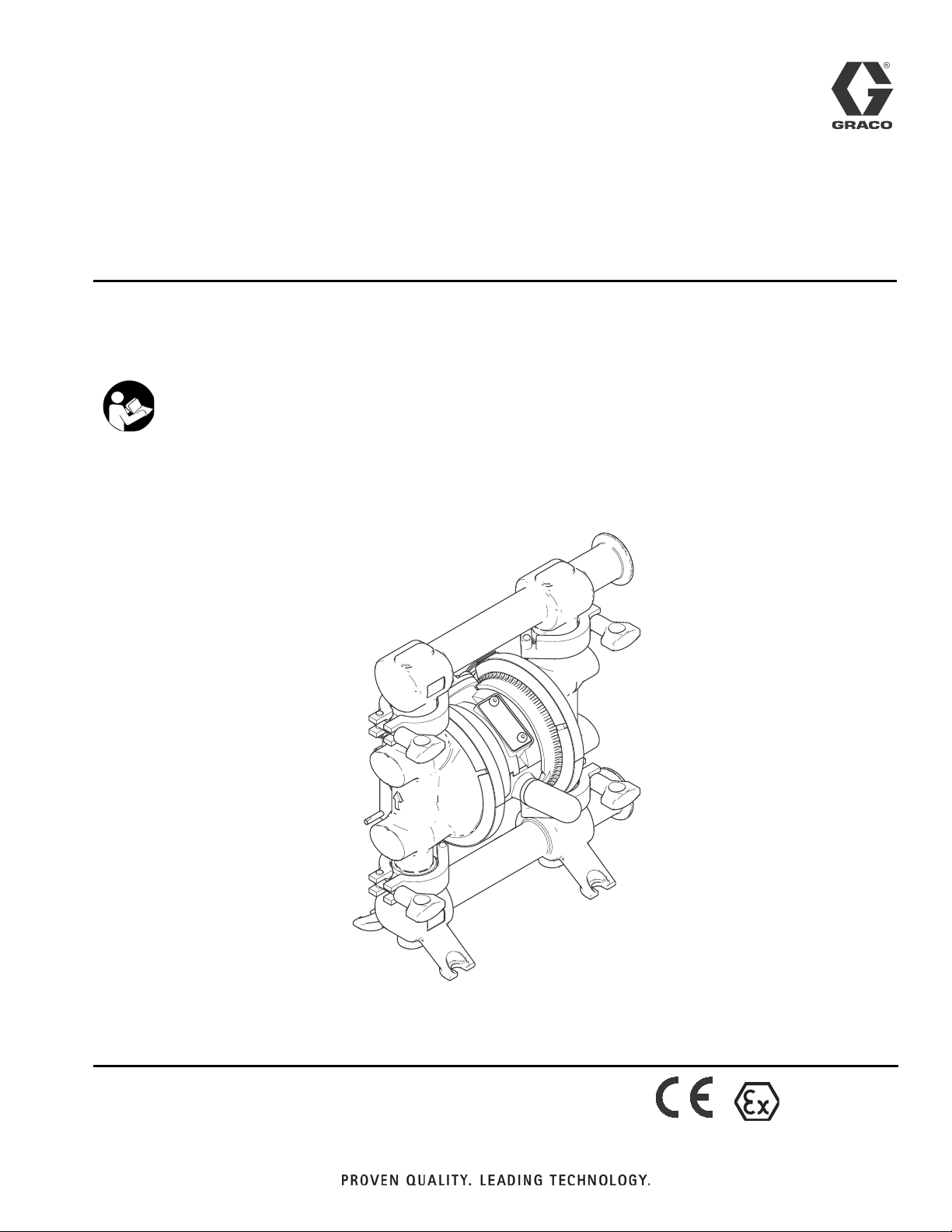
Instructions/Parts List
™
SaniForce
515
Diaphragm Pumps
For use in sanitary applications. For professional use only.
Important Safety Instructions
Read all warnings and instructions in this
manual. Save these instructions.
100 psi (0.7 MPa, 6.9 bar) Maximum Fluid Working Pressure
100 psi (0.7 MPa, 6.9 bar) Maximum Air Input Pressure
3A1973B
EN
ti17529a
II 2 GD c llA T4
Page 2

Models
Contents
Models . . . . . . . . . . . . . . . . . . . . . . . . . . . . . . . . . . . 2
Warnings . . . . . . . . . . . . . . . . . . . . . . . . . . . . . . . . . 4
Installation . . . . . . . . . . . . . . . . . . . . . . . . . . . . . . . . 6
General Information . . . . . . . . . . . . . . . . . . . . . . 6
Tighten Clamps Before First Use . . . . . . . . . . . . 6
Grounding . . . . . . . . . . . . . . . . . . . . . . . . . . . . . . 6
Mounting . . . . . . . . . . . . . . . . . . . . . . . . . . . . . . . 7
Air Line . . . . . . . . . . . . . . . . . . . . . . . . . . . . . . . . 7
Fluid Suction Line . . . . . . . . . . . . . . . . . . . . . . . . 7
Fluid Outlet Line . . . . . . . . . . . . . . . . . . . . . . . . . 8
Changing the Orientation of the
Fluid Inlet and Outlet Ports . . . . . . . . . . . . . . 9
Air Exhaust Ventilation . . . . . . . . . . . . . . . . . . . 10
Operation . . . . . . . . . . . . . . . . . . . . . . . . . . . . . . . . 11
Pressure Relief Procedure . . . . . . . . . . . . . . . . 11
Sanitize the Pump Before First Use . . . . . . . . . 11
Starting and Adjusting the Pump . . . . . . . . . . . 11
Pump Shutdown . . . . . . . . . . . . . . . . . . . . . . . . 11
Maintenance . . . . . . . . . . . . . . . . . . . . . . . . . . . . . . 12
Air Valve Lubrication . . . . . . . . . . . . . . . . . . . . . 12
Flushing . . . . . . . . . . . . . . . . . . . . . . . . . . . . . . . 12
Tightening Connections . . . . . . . . . . . . . . . . . . . 12
Preventive Maintenance Schedule . . . . . . . . . . 12
Troubleshooting . . . . . . . . . . . . . . . . . . . . . . . . . . . 13
Service . . . . . . . . . . . . . . . . . . . . . . . . . . . . . . . . . . 14
Air Valve . . . . . . . . . . . . . . . . . . . . . . . . . . . . . . 14
Ball Check Valve . . . . . . . . . . . . . . . . . . . . . . . . 16
Standard Diaphragms . . . . . . . . . . . . . . . . . . . . 16
Overmolded PTFE Diaphragms . . . . . . . . . . . . 18
Air Center Service . . . . . . . . . . . . . . . . . . . . . . . 19
Parts . . . . . . . . . . . . . . . . . . . . . . . . . . . . . . . . . . . . 20
Fluid Section Repair Kits . . . . . . . . . . . . . . . . . . . 22
Dimensions . . . . . . . . . . . . . . . . . . . . . . . . . . . . . . . 23
Performance Charts . . . . . . . . . . . . . . . . . . . . . . . . 24
Technical Data . . . . . . . . . . . . . . . . . . . . . . . . . . . . 26
Graco Standard Warranty . . . . . . . . . . . . . . . . . . . 28
Graco Information . . . . . . . . . . . . . . . . . . . . . . . . . 28
Models
Model Seats O-Rings Balls Diaphragms
FD5111
FD5113
FD5122
FD5611
FD5613
FD5622
PTFE
Stainless Steel
EPDM
PTFE 2-Piece PTFE
PTFE Overmolded PTFE
Santoprene Santoprene
PTFE 2-Piece PTFE
PTFE Overmolded PTFE
Santoprene Santoprene
2 3A1973B
Page 3
Material Certification
Reference: SaniForce Product Family
Issue Date: November 1, 2011
All fluid contact materials in the SaniForce product family are FDA-Compliant and meet the United States
Code of Federal Regulations (CFR) Title 21, Section 177 or are of a corrosion resistant grade Stainless
Steel. This includes the below product groups:
1. SaniForce 515, 1040, 1590, 2150 Air-Operated Double Diaphragm Pumps
2. SaniForce 1590, 3150 HS Air-0perated Double Diaphragm Pumps
3. SaniForce 1590, 3150 HS 3-A Certified Air-Operated Double Diaphragm Pumps
4. SaniForce 5:1, 6:1 and 12:1 Air-Operated Piston Pumps
5. SaniForce Diaphragm Pump and Piston Pump Drum Unloaders
6. SaniForce Diaphragm Pump and Piston Pump Bin Evacuation Systems
Models
Bradley A. Byron
Quality Manager
Graco Inc.
3A1973B 3
Page 4
Warnings
Warnings
The following warnings are for the setup, use, grounding, maintenance, and repair of this equipment. The exclamation point symbol alerts you to a general warning and the hazard symbol refers to procedure-specific risk. When
these symbols appear in the body of this manual, refer back to these Warnings. Additional, product-specific warnings
may be found throughout the body of this manual where applicable.
WARNING
FIRE AND EXPLOSION HAZARD
Flammable fumes, such as solvent and paint fumes, in work area can ignite or explode. To help prevent
fire and explosion:
• Use equipment only in well ventilated area.
• Eliminate all ignition sources; such as pilot lights, cigarettes, portable electric lamps, and plastic
drop cloths (potential static arc).
• Keep work area free of debris, including solvent, rags and gasoline.
• Do not plug or unplug power cords, or turn power or light switches on or off when flammable fumes
are present.
• Ground all equipment in the work area. See Grounding instructions.
• Use only grounded hoses.
• Hold gun firmly to side of grounded pail when triggering into pail. Do not use pail liners unless they
are antistatic or conductive.
• Stop operation immediately if static sparking occurs or you feel a shock. Do not use equipment
until you identify and correct the problem.
• Keep a working fire extinguisher in the work area.
TOXIC FLUID OR FUMES HAZARD
Toxic fluids or fumes can cause serious injury or death if splashed in the eyes or on skin, inhaled, or
swallowed.
• Read MSDS’s to know the specific hazards of the fluids you are using.
• Route exhaust away from work area. If diaphragm ruptures, fluid may be exhausted into the air.
• Store hazardous fluid in approved containers, and dispose of it according to applicable guidelines.
PRESSURIZED EQUIPMENT HAZARD
Fluid from the equipment, leaks, or ruptured components can splash in the eyes or on skin and cause
serious injury.
• Follow the Pressure Relief Procedure when you stop spraying/dispensing and before cleaning,
checking, or servicing equipment.
• Tighten all fluid connections before operating the equipment.
• Check hoses, tubes, and couplings daily. Replace worn or damaged parts immediately.
4 3A1973B
Page 5
Warnings
WARNING
EQUIPMENT MISUSE HAZARD
Misuse can cause death or serious injury.
• Do not operate the unit when fatigued or under the influence of drugs or alcohol.
• Do not exceed the maximum working pressure or temperature rating of the lowest rated system
component. See Technical Data in all equipment manuals.
• Use fluids and solvents that are compatible with equipment wetted parts. See Technical Data in all
equipment manuals. Read fluid and solvent manufacturer’s warnings. For complete information
about your material, request MSDS from distributor or retailer.
• Do not leave the work area while equipment is energized or under pressure.
• Turn off all equipment and follow the Pressure Relief Procedure when equipment is not in use.
• Check equipment daily. Repair or replace worn or damaged parts immediately with genuine
manufacturer’s replacement parts only.
• Do not alter or modify equipment. Alterations or modifications may void agency approvals and create
safety hazards.
• Make sure all equipment is rated and approved for the environment in which you are using it.
• Use equipment only for its intended purpose. Call your distributor for information.
• Route hoses and cables away from traffic areas, sharp edges, moving parts, and hot surfaces.
• Do not kink or over bend hoses or use hoses to pull equipment.
• Keep children and animals away from work area.
• Comply with all applicable safety regulations.
BURN HAZARD
Equipment surfaces and fluid that’s heated can become very hot during operation. To avoid severe
burns:
• Do not touch hot fluid or equipment.
PERSONAL PROTECTIVE EQUIPMENT
Wear appropriate protective equipment when in the work area to help prevent serious injury, including
eye injury, hearing loss, inhalation of toxic fumes, and burns. This protective equipment includes but is
not limited to:
• Protective eyewear and hearing protection.
• Respirators, protective clothing, and gloves as recommended by the fluid and solvent manufacturer.
3A1973B 5
Page 6
Installation
Installation
General Information
• The typical installation shown in FIG. 2, page 8, is
only a guide for selecting and installing system components. Contact your Graco distributor for assistance in planning a system to suit your needs.
• Always use genuine Graco parts and accessories.
• Reference numbers and letters in parentheses refer
to the callouts in the figures.
The pump is heavy and may cause injury if dropped.
Lift the pump by grasping the outlet manifold securely.
ti17654a
9a
Y
8
9b
9c
If dropped, the pump may rupture. To avoid serious
injury from splashing fluid, follow the Pressure Relief
Procedure on page 11 before moving the pump.
To reduce the risk of serious injury due to burns, insulate the pump before pumping hot fluids.
Tighten Clamps Before First Use
After you unpack the pump, and before you use it for the
first time, check all clamps and tighten as necessary.
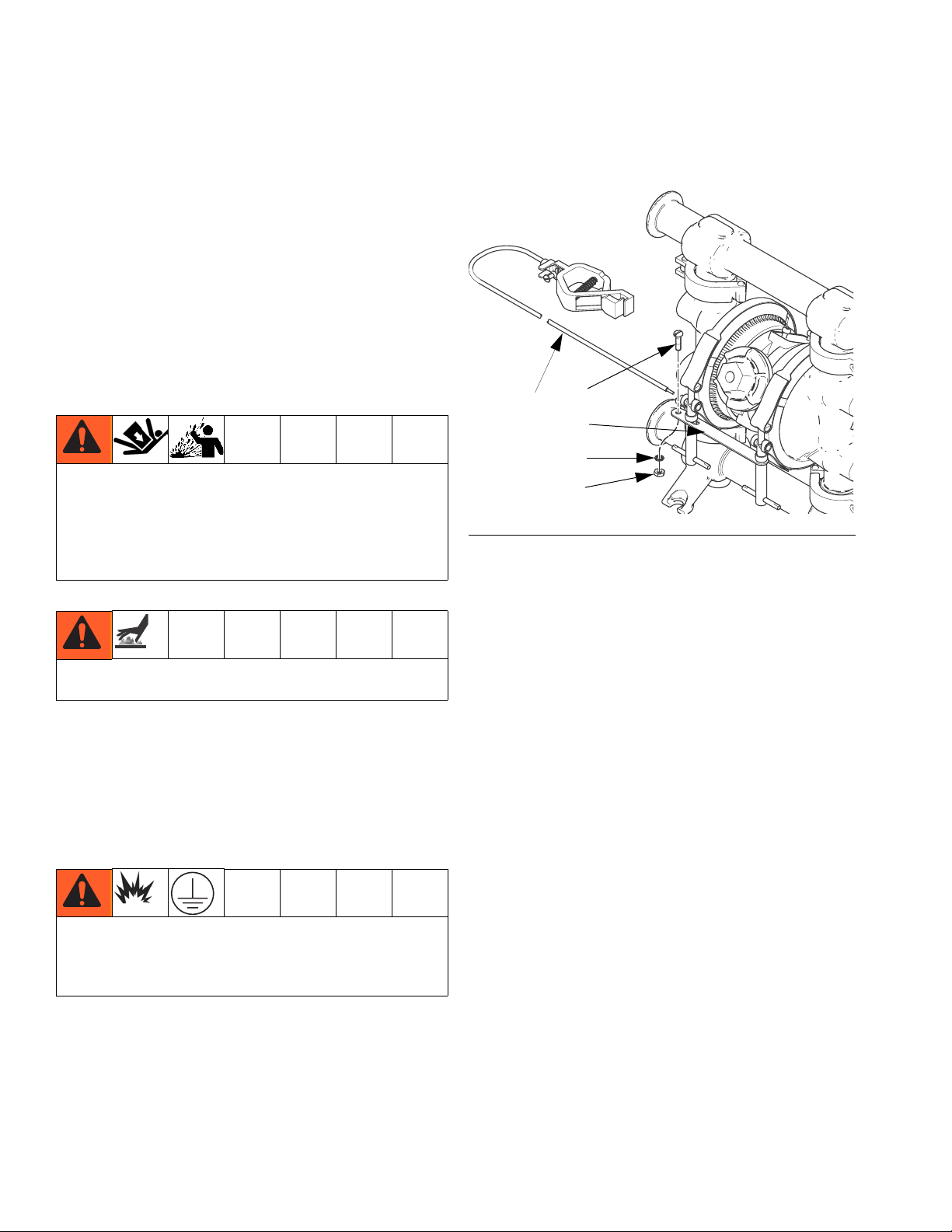
Grounding
The equipment must be grounded. Grounding reduces
the risk of static and electric shock by providing an
escape wire for the electrical current due to static build
up or in the event of a short circuit.
FIG. 1: Ground the pump
• Fluid hoses: Use only grounded hoses with a maximum of 500 ft. (150 m) combined hose length to
ensure grounding continuity.
• Air compressor: Follow the manufacturer’s recommendations.
• All solvent pails used when flushing: Follow the local
code. Use only metal pails, which are conductive.
Do not place the pail on a non-conductive surface,
such as paper or cardboard, which interrupts the
grounding continuity.
• Fluid supply container: Follow the local code.
• Pump: Attach a ground wire (Y) to the grounding
strip (8) with the screw (9a), lockwasher (9b), and
nut (9c), as shown in F
Connect the clamp end of the ground wire to a true
earth ground. Order Part No. 238909 Ground Wire
and Clamp.
6 3A1973B
IG. 1, and per local code.
Page 7
Mounting
Installation
NOTICE
Pump exhaust air may contain contaminants that can
contaminate the fluid supply. Ventilate to a remote
area. See Air Exhaust Ventilation on page 10.
• Be sure the mounting surface can support the
weight of the pump, hoses, and accessories, as well
as the stress caused during operation.
• For all mountings, be sure the pump is bolted
directly to the mounting surface.
• For ease of operation and service, mount the pump
so the air valve cover, air inlet, and fluid inlet and
outlet ports are easily accessible.
Air Line
Trapped air can cause the pump to cycle unexpectedly,
which could result in serious injury, including splashing
in the eyes or on the skin, injury from moving parts, or
contamination from hazardous fluids. A bleed-type
master air valve (B) is required in the system to relieve
air trapped between this valve and the pump.
See F
IG. 2, page 8.
1. Install the air line accessories as shown in FIG. 2.
Mount these accessories on the wall or on a
bracket. Be sure the air line supplying the accessories is grounded.
a. Install an air regulator/filter assembly (C) and
gauge to control the fluid pressure. The fluid
outlet pressure will be the same as the setting of
the air regulator. The air line filter removes
harmful dirt and moisture from the compressed
air supply.
In the step below, do not connect the quick-disconnect
coupler (D) on the air hose to the mating fitting on the
pump until you are ready to operate the pump. Connecting the coupler too early can result in unintentional
operation of the pump, leading to serious injury from
moving parts, splashing fluid in the eyes or on the skin,
and contact with hazardous fluids.
2. Install a grounded, flexible air hose (A) between the
accessories and the 1/4 npt(f) pump air inlet. Use a
minimum 1/4 in. (6.3 mm) ID air hose. Screw an air
line quick disconnect coupler (D) onto the end of the
air hose (A), and screw the mating fitting into the
pump air inlet snugly.
Fluid Suction Line
1. Use flexible, grounded fluid hoses (F). The inlet fits
sanitary tubing of 1 to 1.5-inch OD.
2. For best sealing results, use a standard Tri-Clamp®
style sanitary gasket of a flexible material such as
EPDM or Buna-N.
3. If the fluid inlet pressure to the pump is more than
25% of the outlet working pressure, the ball check
valves will not close fast enough, resulting in inefficient pump operation. Excessive inlet fluid pressure
also will shorten diaphragm life. Approximately 3 - 5
psi (0.02 - 0.03 MPa, 0.21-0.34 bar) should be adequate for most materials.
4. For maximum suction lift (wet and dry), see Techni-
cal Data, page 26. For best results, always install
the pump as close as possible to the material
source.
b. Locate one bleed-type master air valve (B)
close to the pump and use it to relieve trapped
air. See the WARNING above. Locate the other
master air valve (E) upstream from all air line
accessories and use it to isolate them during
cleaning and repair.
3A1973B 7
Page 8
Installation
Fluid Outlet Line
A fluid drain valve (G) is required to relieve pressure in
the hose if it is plugged. The drain valve reduces the
risk of serious injury, including splashing in the eyes or
on the skin, or contamination from hazardous fluids
when relieving pressure. Install the valve close to the
pump fluid outlet. See F
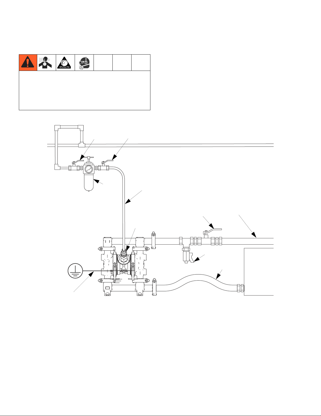
Key:
A Air supply line
B Bleed-type master air valve
(required for pump)
C Air regulator/filter assembly
D Air line quick disconnect
E Master air valve (for accessories)
F Flexible fluid suction line
G Fluid drain valve (required)
H Fluid shutoff valve
J Flexible fluid line
Y Ground wire (required; see
page 6 for installation
instructions).
IG. 2.
E
B
C
D
1. Use flexible grounded fluid hoses (J).
2. For best sealing results, use a standard Tri-Clamp®
style sanitary gasket of a flexible material such as
EPDM, Buna-N.
3. Install a fluid drain valve (G) near the fluid outlet.
See the WARNING, and F
IG. 2.
4. Install a shutoff valve (H) in the fluid outlet line.
A
H
J
G
F
Y
ti17652a
F
IG. 2: Typical Floor-Mount Installation
8 3A1973B
Page 9
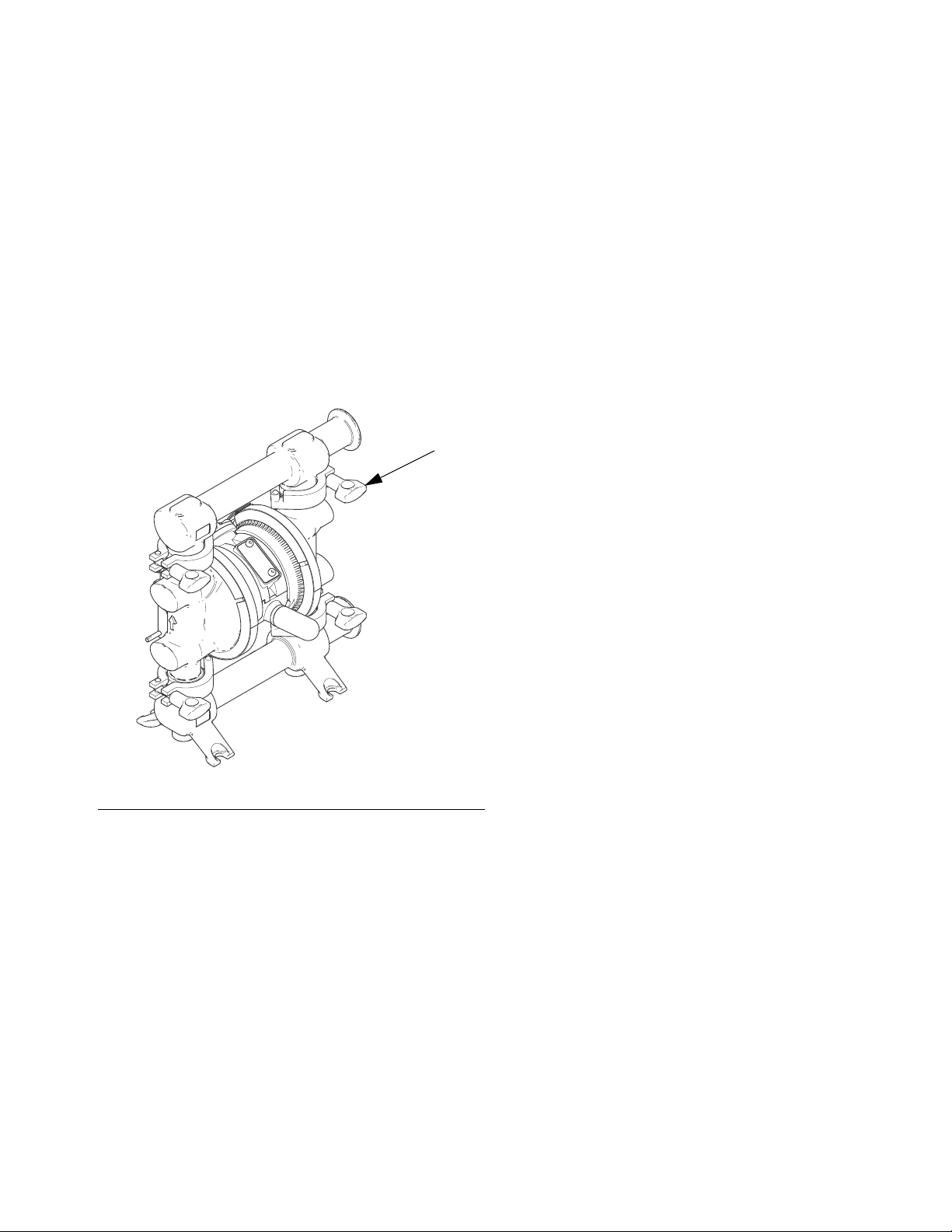
Changing the Orientation of the Fluid Inlet and Outlet Ports
The pump is shipped with the ports facing the same
direction. To reverse the orientation of the ports:
1. Remove the clamps (12) holding the inlet and/or
outlet manifold to the covers.
NOTE: Inspect the o-rings and replace as needed.
2. Reverse the manifold and reattach. Install and
tighten clamps snugly.
12
Installation
ti17529a
F
IG. 3: Reverse the Manifolds
3A1973B 9
Page 10

Installation
Air Exhaust Ventilation
To avoid serious injury from explosion or hazardous
fluids:
• ensure the system is properly ventilated for your
type of installation.
• vent the exhaust away from people, animals, food
handling areas, and all sources of ignition
• place an appropriate container at the end of the air
exhaust line to catch fluid. If a diaphragm ruptures,
fluid will exhaust with the air. See F
The air exhaust port is 3/8 npt(f). Do not restrict the air
exhaust port. Excessive exhaust restriction can cause
erratic pump operation.
Key:
A Air supply line
B Bleed-type master air valve
(required for pump)
C Air regulator
D Air line quick disconnect
E Master air valve (for accessories)
PMuffler
T Grounded air exhaust hose
U Container for remote air exhaust
IG. 4.
To provide a remote exhaust:
1. Remove the muffler (P) from the pump air exhaust
port.
2. Install a grounded air exhaust hose (T) and connect
the muffler (P) to the other end of the hose. The
minimum size for the air exhaust hose is 3/8 in.
(9.5 mm) ID. If a hose longer than 15 ft (4.57 m) is
required, use a larger diameter hose. Avoid sharp
bends or kinks in the hose.
3. Place a container (U) at the end of the air exhaust
line to catch fluid in case a diaphragm ruptures. See
F
IG. 4.
E
B
A
IG. 4: Venting Exhaust Air
F
C
D
T
U
P
ti17648a
10 3A1973B
Page 11

Operation
Operation
Pressure Relief Procedure
The equipment stays pressurized until pressure is
manually relieved. To reduce the risk of serious injury
from pressurized fluid or splashing fluid, follow this
procedure whenever you stop pumping and before
cleaning, checking, or servicing equipment.
1. Shut off the air to the pump.
2. Open the dispensing valve, if used.
3. Open the fluid drain valve to relieve fluid pressure.
Have a container ready to catch the drainage.
Sanitize the Pump Before First Use
It is the user’s responsibility to properly sanitize the
pump before first use. It is up to the user whether this
will include disassembling and cleaning individual parts
or simply flushing pump with a sanitizing solution. As
necessary, follow the steps under Starting and Adjust-
ing the Pump, at right, under Flushing on page 12, or
under Disassembly in the Service section, starting on
page 16.
Starting and Adjusting the Pump
1. Be sure the pump is properly grounded. Refer to
Grounding on page 6.
2. Check connections to be sure they are tight. Tighten
fluid inlet and outlet connections securely.
3. Connect suction line (F) to material supply.
NOTE: If fluid inlet pressure to the pump is more than
25% of outlet working pressure, the ball check valves
will not close fast enough, resulting in inefficient pump
operation.
4. Place the end of fluid hose (J) into an appropriate
container.
5. Close the fluid drain valve (G).
6. Back out the air regulator (C) knob, and open all
bleed-type master air valves (B, E).
7. If the fluid hose has a dispensing device, hold it
open while continuing with the following step.
8. Slowly increase air pressure with the air regulator
(C) until the pump starts to cycle. Allow the pump to
cycle slowly until all air is pushed out of the lines
and the pump is primed.
Pump Shutdown
To avoid serious injury from splashing fluid, never
move or lift a pump under pressure. If dropped, the
fluid section may rupture. Always follow the Pressure
Relief Procedure before lifting the pump.
3A1973B 11
At the end of the work shift, relieve pressure.
Page 12
Maintenance
Maintenance
Air Valve Lubrication
The air valve is designed to operate unlubricated, however if lubrication is desired, every 500 hours of operation (or monthly) remove the hose from the pump air
inlet and add two drops of machine oil to the air inlet.
NOTICE
Do not over-lubricate the pump. Oil is exhausted
through the muffler and could contaminate your fluid
supply or other equipment. Excessive lubrication also
can cause the pump to malfunction.
Flushing
Insert suction tube into cleaning solution. Open air regulator to supply low pressure air to the pump. Run the
pump long enough to thoroughly clean the pump and
hoses. Close the air regulator. Remove the suction tube
from the cleaning solution and drain pump. Place suction tube in the fluid to be pumped.
Tightening Connections
Before each use, check all hoses for wear or damage,
and replace as necessary. Check to be sure all connections are tight and leak-free.
Preventive Maintenance Schedule
Establish a preventive maintenance schedule, based on
the pump’s service history. This is especially important
for prevention of spills or leakage due to diaphragm failure.
Flush the pump often enough to prevent the fluid you
are pumping from drying or freezing in the pump and
damaging it. Flushing schedule will be based on what
the pump is being used for. Use a compatible cleaning
solution and always cycle the pump during the entire
flushing process.
Always flush the pump and relieve the pressure before
storing it for any length of time.
12 3A1973B
Page 13
Troubleshooting
PROBLEM CAUSE SOLUTION
Troubleshooting
1. Follow the Pressure Relief Procedure, page 11.
2. Check all possible problems and causes before disassembling the pump.
Pump will not cycle, or cycles once
and stops.
Pump cycles at stall or fails to hold
pressure at stall.
Pump operates erratically. Clogged suction line. Inspect; clear.
Air bubbles in fluid. Suction line is loose. Tighten.
Fluid in exhaust air. Diaphragm ruptured. Replace. See page 16 (standard dia-
Pump exhausts air from clamps. Loose manifolds, damaged seal
Pump leaks fluid from check valves. Worn or damaged check valve o-ring. Inspect; replace. See page 16.
No fluid output, and pumps cycles
rapidly.
Air valve is stuck or dirty. Disassemble and clean air valve. See
page 14. Use filtered air.
Check valve ball is severely worn and
wedged in seat or manifold.
Worn check valve balls, seats, or
o-rings.
Check valve ball wedged in seat. Repair or replace. See page 16.
Worn diaphragm shaft seals. Replace. See page 16 (standard dia-
Sticky or leaking check valve balls. Clean or replace. See page 16.
Diaphragm ruptured. Replace. See page 16 (standard dia-
Restricted exhaust. Remove restriction.
Diaphragm ruptured. Replace. See page 16 (standard dia-
Loose inlet manifold, damaged seal
between manifold and seat, or damaged manifold o-rings.
Loose diaphragm shaft bolt or fluid
side diaphragm plates.
Loose diaphragm shaft bolt or fluid
side diaphragm plates.
Worn diaphragm shaft seals. Replace. See page 16 (standard dia-
between manifold and seat, or damaged manifold o-rings.
Air valve o-ring is damaged. Inspect; replace. See page 14.
Pump mounted incorrectly. Mount the pump in the upright posi-
Replace ball and seat. See page 16.
Replace. See page 16.
phragms).
phragms) or page 18 (overmolded
diaphragms).
phragms) or page 18 (overmolded
diaphragms).
Tighten manifold clamps, or replace
seats or o-rings. See page 16.
Tighten or replace. See page 16
(standard diaphragms).
phragms) or page 18 (overmolded
diaphragms).
Tighten. See page 16 (standard diaphragms).
phragms).
Tighten manifold clamps, or replace
seats or o-rings. See page 16.
tion.
3A1973B 13
Page 14
Service
Service
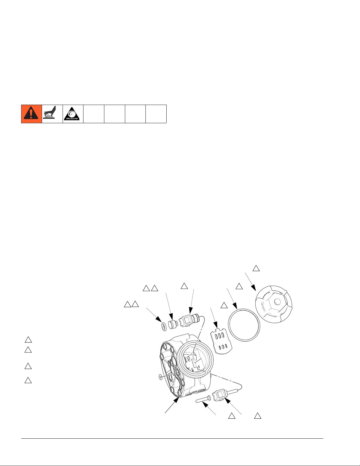
Air Valve
NOTE: Air Valve Repair Kit 241657 is available. Parts
included in the kit are marked †. Use all parts in the kit.
1. Follow the Pressure Relief Procedure, page 11.
2. Remove the air chamber cover (110) and the o-ring
(104).
3. Remove the carriage plungers (107), carriages
(108), carriage pins (109), and valve plate (114)
from the center housing (111).
4. Remove the u-cups (102) from the carriage plungers (107).
5. Clean all parts and inspect them for wear or damage.
NOTE: When instructed to lubricate, apply appropriate
waterproof sanitary lubricant (such as Graco PN
111265).
6. Lubricate the lapped surface of the valve plate
(114), and install with the lapped surface facing up.
7. Lubricate and install the carriage pins (109).
8. Install the carriages (108). Make sure the carriages
engage the clip ends of the carriage pins (109).
9. Lubricate the bores of the center housing (111),
then install the u-cups (102) on the carriage plungers (107), with the u-cups facing toward smaller
end.
10. Slide the carriage plungers into the bores, with the
smaller ends facing toward the center of the
center housing (111). See F
IG. 5.
11. Lubricate and install the o-ring (104) on the cover
(110).
12. Screw the cover (110) into the center housing.
Torque to 80 to 100 in-lb. (9.0 to 13.6 N•m).
Note: The center housing may
remain assembled to the air and
fluid covers for this service.
2
3
102†
1
Torque to 80-100 in-lb. (9.0-13.6 N•m).
2
Apply appropriate waterproof sanitary lubricant
(such as Graco PN 111265).
3
Lips must face the smaller end of the carriage
plunger.
4
Smaller ends must face toward the center of the
center housing. Lubricate bores of center housing
before installing.
FIG. 5. Disassemble/Reassemble the Air Valve
1
110
2
2
4
107†
108†
111
104†
114†
2
2
109† 108†
2
ti17557a
2
14 3A1973B
Page 15

Service
2
30
1
12
1
6
20
3
16
13
31
13
21
1
105
1
9a
16
13
9b
3
9c
4
8
14
15
23
20
25
5
31
34
13
1
12
2
1
Apply appropriate waterproof sanitary lubricant to
the threads and inside of clamp.
2
Torque to 80-90 in-lb (9-10 N•m).
3
Air side markings on diaphragm must face housing.
4
Torque to 80-90 in-lb (9-10 N•m) at 100 rpm maximum.
5
Flat side must face toward shaft.
3
TI17530a
FIG. 6: Disassemble/Reassemble the Pump
3A1973B 15
Page 16

Service
Ball Check Valve
Disassembly
NOTE:
• PTFE o-rings should be replaced every time manifolds are removed.
1. Relieve the pressure. Disconnect all hoses.
2. Remove the pump from its mounting.
3. Remove the clamps (12) holding the outlet manifold
(2) to the fluid covers (1). See F
4. Remove the o-rings (13), seats (31), and balls (16).
5. Remove the clamps (12) and the inlet manifold (3).
Remove the o-rings (13), seats (31), and balls (16).
Reassembly
NOTE: When instructed to lubricate, apply appropriate
waterproof sanitary lubricant.
1. Clean all parts and inspect for wear or damage.
Replace parts as needed.
2. Reassemble in the reverse order, following all notes
in F
IG. 6, page 15. Be sure the ball checks and man-
ifolds are assembled exactly as shown. The arrows
(A) on the fluid covers (1) must point toward the outlet manifold (2).
IG. 6.
Standard Diaphragms
NOTE: If your pump uses overmolded PTFE dia-
phragms, see page 18.
Disassembly
1. Relieve the pressure.
2. Remove the manifolds and disassemble the ball
check valves as explained at left.
3. Remove the nuts (34) and the grounding strip (8),
then remove the clamps (6) holding the fluid covers
(1) to the air covers (21). Pull the fluid covers (1) off
the pump. See F
4. Loosen but do not remove the diaphragm shaft bolts
(14), using a 10 mm socket wrench on both bolts.
5. Unscrew one bolt from the diaphragm shaft (105)
and remove the o-ring (15), fluid side diaphragm
plate (23), diaphragm (20), backer (24) used only on
PTFE models, and air side diaphragm plate (25).
See F
IG. 7.
6. Pull the other diaphragm assembly and the diaphragm shaft (105) out of the center housing. Hold
the shaft flats with a 19 mm open end wrench, and
remove the bolt (14) from the shaft. Disassemble
the remaining diaphragm assembly.
7. Clean all parts and replace o-rings as needed.
IG. 6.
16 3A1973B
Page 17

Reassembly
Service
1. Install the diaphragm assembly on one end of the
shaft (105) as follows:
a. Install the o-ring (15) on the shaft bolt (14).
b. Install the fluid side diaphragm plate (23) on the
bolt so the rounded side faces the diaphragm
(20).
c. Install the diaphragm (20). Make certain the
side marked AIR SIDE faces the center housing.
d. On PTFE models only, install the backer on the
bolt. Make certain the side marked AIR SIDE
faces the center housing.
e. Install the air side diaphragm plate (25) so the
rounded side faces the diaphragm (20).
f. Screw the bolt into the shaft (105) hand tight.
2. Grease the length and ends of the diaphragm shaft
(105), and slide it through the housing.
5
25
15
4
14
23
1 2
6
1
A
1
Apply appropriate waterproof sanitary lubricant to the
threads and inside of clamp.
2
Torque to 80-90 in-lb (9-10 N•m).
3
Air side markings on diaphragm must face housing.
4
Torque to 80-90 in-lb (9-10 N•m) at 100 rpm maximum.
5
Flat side must face toward shaft.
F
IG. 7: Standard Diaphragm
20
1
105
3
ti17650a
3. Assemble the other diaphragm assembly to the
shaft as explained in step 1.
4. Hold one shaft bolt (14) with a wrench and torque
the other bolt to 80-90 in-lb (9-10 N
•m) at 100 rpm
maximum.
NOTE: When you install the clamps in Step 5, orient the
center housing so the air inlet is approximately 45°
above horizontal and the muffler is approximately horizontal.
5. Position the fluid covers (1) and the center housing
so the arrows (A) on the covers face the same direction. See F
IG. 7. Apply appropriate, waterproof sani-
tary lubricant and install the clamps around the fluid
and air covers. Install the grounding strip on the
clamps, and torque the t-handle nuts to 80-90 in-lb
(9-10 N•m).
6. Reassemble the ball check valves and manifolds as
explained on page 16.
3A1973B 17
Page 18

Service
Overmolded PTFE Diaphragms
NOTE: If your pump uses standard diaphragms, see
page 16.
Disassembly
1. Relieve the pressure.
2. Remove the manifolds and disassemble the ball
check valves as explained on page 16.
3. Remove the clamps (6) holding the fluid covers (1)
to the air covers (21). Pull the fluid covers (1) off the
pump. See F
4. Once the fluid covers are removed, the diaphragm
on the side of the pump which was last pressurized
with air will be separated from the center section/air
cover. This allows you to grip the diaphragms.
5. Diaphragms are assembled handtight. To loosen,
grip both diaphragms securely around the outer
edge and rotate counterclockwise. One diaphragm
assembly will come free and the other will remain
attached to the shaft. Remove the freed diaphragm
(20) and air side plate (25).
6. Pull the opposite diaphragm assembly and shaft
(105) out of the center housing. Hold the shaft flats
with a 19 mm open end wrench and remove the diaphragm and air side plate from the shaft.
7. Clean all parts and replace as needed.
IG. 8.
20 25
3
6
1
105
1 2
6
1
ti17651a
A
1
Apply appropriate waterproof sanitary lubricant to the threads
and inside of clamp.
2
Torque to 80-90 in-lb (9-10 N•m).
3
Flat side must face toward shaft.
FIG. 8: Overmolded PTFE Diaphragm
Reassembly
To reduce the risk of serious injury, including
amputation, do not put your fingers or hand between
the air cover and the diaphragm.
1. Assemble the air side plate (25) onto the diaphragm
(20). The wide, radiused side of the plate must face
the diaphragm. Screw the assembly (diaphragm and
plate) onto the shaft (105) hand tight.
2. Grease the length and ends of the diaphragm shaft
(105). Insert the shaft/diaphragm assembly into one
side of the pump.
3. Assemble the other diaphragm assembly to the
shaft as explained in Step 1.
4. Push the assembly down on the work surface to
raise the diaphragm up and out so the edges can be
gripped. Hand tighten the second diaphragm onto
the shaft.
18 3A1973B
Page 19

NOTE: When you install the clamps in Step 5, orient the
center housing so the air inlet is approximately 45°
above horizontal and the muffler is approximately horizontal.
5. Position the fluid covers (1) and the center housing
so the arrows (A) on the covers face the same direction. See F
tary lubricant and install the clamps around the fluid
and air covers. Install the grounding strip on the
clamps, and torque the t-handle nuts to 80-90 in-lb
(9-10 N•m).
6. Reassemble the ball check valves and manifolds as
explained on page 14.
IG. 8. Apply appropriate, waterproof sani-
Air Center Service
Remove air covers for easier replacement of u-cups and
to replace the poppet o-ring, if needed. See parts illustration, page 20.
Service
1. Follow all disassembly directions for diaphragm service. See Standard Diaphragms, page 16, or
Overmolded PTFE Diaphragms, page 18.
2. Remove the muffler (103).
3. Use a phillip’s screwdriver to remove 6 screws (22),
and remove one air cover (21) and gasket (112).
4. Remove u-cup (102) and poppet o-ring (101).
5. Lubricate and install new u-cup (102) and poppet
o-ring (101). U-cup lips must face out of center
housing.
6. Reinstall the gasket (112) and air cover (21). Torque
screws (22) to 35-45 in-lb (4-5 N•m).
7. Repeat for other side.
8. Reinstall the muffler (103).
9. Follow all reassembly directions for diaphragm service. See page 17 for standard diaphragms or page
18 for overmolded diaphragms.
3A1973B 19
Page 20

Parts
Parts
12
16
13
31
13
30
8
110
1
104
108
108
1
2
7
107
1
6
102
109
114
1
1
111
1
101
104
3
20
1
6
1
102
9
113
112
21
5
22
103
16
13
31
13
12
1
105
1
9a
TI18040a
34
9b
9c
4
8
2
3
14
1
Apply appropriate waterproof sanitary lubricant.
2
Torque to 80-90 in-lb (9-10 N•m).
3
Air side markings on diaphragm must face housing.
4
Torque to 80-90 in-lb (9-10 N•m) at 100 rpm maximum.
5
Torque to 35-45 in-lb (4-5 N•m).
6
Lips must face the smaller end of the carriage plunger.
7
Smaller ends must face toward the center of the center
housing.
8
Torque to 80-100 in-lb (9-11 N•m).
9
Lips must face out of center housing.
10
Flat side must face toward shaft.
15
23
20
25
10
3
20 3A1973B
Page 21

Parts
Ref. Part Description Qty.
1 278379 COVER, fluid 2
2 278378 MANIFOLD, outlet 1
3 278377 MANIFOLD, inlet 1
4 290045 PLATE, identification, not shown 1
6 262684 CLAMP, vee; includes t-handle nut
(Ref. 34)
8 191079 STRIP, grounding 1
9 262687 KIT, ground fasteners, stainless
steel; includes Refs. 9a, 9b, and
9c
9a ----- SCREW, phillips head,
#10-24 x 0.75
9b ----- WASHER, #10, flat 1
9c ----- NUT, #10-24 x 0.125 1
12 118598 CLAMP, sanitary, 1.5 in. 4
13* O-RING 8
----- PTFE
----- EPDM
14 SCREW, 1/4-20 x 1
113747 Hex head flange (for standard
diaphragms)
16H912 Socket head set (for over-
molded diaphragms)
15* 110004 O-RING (not used with over-
molded diaphragms)
16* BALL 4
112946 Santoprene (FD5122 and
FD5622)
108639 PTFE (FD5111, FD5611,
FD5113, FD5613)
17 111183 RIVET, pop, not shown 2
19 262640 AIR MOTOR, see Air Motor Parts 1
20* DIAPHRAGM 2
----- Santoprene (FD5122, FD5162)
----- Overmolded PTFE (FD5113
and FD5163)
----- PTFE (FD5111 and FD5611)
21 278380 COVER, air 2
22 114882 SCREW, phillips, pan head
#12-14 x 7/8
23 16M908 PLATE, diaphragm, fluid side (not
used with overmolded diaphragms)
24* 16H681 DIAPHRAGM, backup (FD5111
and FD5611)
12
Ref. Part Description Qty.
25 PLATE, diaphragm, air side 2
195025 For use with standard dia-
phragms
16M001 For use with overmolded dia-
phragms
2
30▲ LABEL, warning 1
188621 English
198382 Multilingual
31 262785 KIT, seats, ball check, set of 4 1
34 ----- NUT, t-handle; included with vee
1
clamp (Ref. 6)
Air Motor Parts
Ref. Part Description Qty.
101* 114866 O-RING 2
102†* 108808 U-CUP 4
103 112933 MUFFLER 1
104†* 162942 O-RING; included with exhaust
cover (Ref. 113) and air chamber
2
105 192601 SHAFT 1
2
107† 15Y825 PLUNGER, carriage 2
108† 192595 CARRIAGE 2
2
109† 192596 PIN, carriage 2
110 262686 COVER, air chamber; includes
111 ----- HOUSING, center 1
112* 192765 GASKET 2
113 262685 COVER, exhaust; includes o-ring
114† 194269 PLATE, valve 1
* These parts are included the the Fluid Section
Repair Kit, sold separately. See page 22 for the correct kit for your model.
† These parts are included in Air Valve Repair Kit
241657, sold separately.
▲ Replacement Warning labels, signs, tags, and cards
are available at no cost.
----- These parts are not sold separately.
2
2
cover (Ref. 110)
o-ring (Ref. 104)
(Ref. 104)
2
1
1
1
3A1973B 21
Page 22

Fluid Section Repair Kits
Fluid Section Repair Kits
Fluid Section Repair Kits follow the numbering of your pump model, but use FK instead of FD for the first two digits.
For example, order repair kit FK5111 for pump FD5111.
Pump Model Repair Kit
FD5111 FK5111
FD5113 FK5113
FD5122 FK5122
FD5611 FK5611
FD5613 FK5613
FD5622 FK5622
22 3A1973B
Page 23

Dimensions
12.7 in.
(323 mm)
10.0 in.
(254 mm)
Dimensions
10.9 in.
(277 mm)
6.4 in.
(163 mm)
8.4 in.
(213 mm)
Pump Mounting
Hole Pattern
1.6 in.
(41 mm)
4.3 in.
(109 mm)
7.0 in.
(178 mm)
7.0 in.
(178 mm)
ti17653a
3A1973B 23
Page 24

Performance Charts
Performance Charts
Fluid Outlet Pressure
Test Conditions: Pump tested in water with inlet submerged.
CYCLES PER MINUTE
standard diaphragms; overmolded diaphragms
FLUID OUTLET PRESSURE—psi (MPa, bar)
100
(0.7, 7)
80
(0.55, 5.5)
60
(0.41, 4.1)
40
(0.28, 2.8)
20
(0.14, 1.4)
46; 64
B
C
2
(7.6)
91; 128 137; 192 182; 256 228; 319
A
4
(15.2)
6
(22.7)
8
(30.3)
273; 383
Fluid Pressure Curves
319; 447
A at 100 psi (0.7 MPa, 7 bar) air pressure
B at 70 psi (0.48 MPa, 4.8 bar) air pressure
C at 40 psi (0.28 MPa, 2.8 bar) air pressure
10
(37.9)
12
(45.4)
14
(53.0)
364; 511
16
(60.6)
FLUID FLOW—gpm (lpm)
To find Fluid Outlet Pressure (psi/MPa/bar) at a
specific fluid flow (gmp/lpm) and operating air pressure (psi/MPa/bar):
1. Locate fluid flow rate along bottom of chart.
2. Follow vertical line up to intersection with
selected fluid outlet pressure curve.
3. Follow left to scale to read fluid outlet pressure.
24 3A1973B
Page 25

Air Consumption
Test Conditions: Pump tested in water with inlet submerged.
CYCLES PER MINUTE
standard diaphragms; overmolded diaphragms
Performance Charts
30
(0.84)
25
(0.70)
20
(0.56)
46; 64
91; 128 137; 192 182; 256 228; 319
Air Consumption Curves
A at 100 psi (0.7 MPa, 7 bar) air pressure
B at 70 psi (0.48 MPa, 4.8 bar) air pressure
C at 40 psi (0.28 MPa, 2.8 bar) air pressure
273; 383
319; 447
A
364; 511
B
15
(0.42)
10
(0.28)
5
(0.14)
C
AIR CONSUMPTION—scfm (cubic meters/min.)
2
(7.6)
4
(15.2)
6
(22.7)
8
(30.3)
10
(37.9)
12
(45.4)
14
(53.0)
16
(60.6)
FLUID FLOW—gpm (lpm)
To find Pump Air Consumption (scfm or m3/min) at
a specific fluid flow (gmp/lpm) and operating air pressure (psi/MPa/bar):
1. Locate fluid flow rate along bottom of chart.
2. Follow vertical line up to intersection with
selected air consumption curve.
3. Follow left to scale to read air consumption.
3A1973B 25
Page 26

Technical Data
Technical Data
SaniForce 515
US Metric
Maximum fluid working pressure 100 psi 0.7 MPa, 7 bar
Air pressure operating range* 20-100 psi 0.14-0.7 MPa, 1.4-7 bar
Maximum air consumption 28 scfm
Air consumption at 70 psi/20 gpm
Maximum free-flow delivery 16 gpm 61 l/min
Recommended cycle rate for continuous duty 182 cycles per minute
Maximum size pumpable solids 3/32 in. 2.4 mm
Maximum viscosity 10,000 cps
Environmental temperature range 40°–120°F 4°–49°C
Minimum fluid temperature 40°F 4°C
Maximum fluid operating temperature
(Do not exceed the lowest maximum depending on the diaphragm, ball, and seat used in your pump.)
PTFE 220°F 104.4°C
Santoprene® 180°F (82.2°C)
EPDM 275°F (135°C)
Stainless steel 250°F (121.1°C)
Maximum suction lift
Dry
Wet
Maximum pump speed
Standard Diaphragms 400 cycles per minute
Overmolded Diaphragms 500 cycles per minute
Fluid flow per cycle*
Standard Diaphragms 0.04 gallons 0.14 liters
Overmolded Diaphragms
Noise (dBa)
Maximum sound pressure
Inlet/Outlet Sizes
Air inlet size
Air exhaust port size
Fluid inlet size 1.5 in. sanitary flange
Fluid outlet size 1.5 in. sanitary flange
18 scfm 0.5 m
15 ft. 4.6 meters
25 ft. 7.6 meters
0.03 gallons 0.11 liters
78 dBa @ 70 psi (0.48 MPa, 4.8 bar)
1/4 in. npt(f)
3/8 npt(f)
0.8 m
3
/minute
3
/minute
26 3A1973B
Page 27

Technical Data
Materials of Construction**
Wetted materials on all models 316 SST
Wetted material depending on model EPDM, PTFE, Santoprene® (CAUTION: Santoprene® may
be used only with non-fatty, non-oily foods or alcohols up to
15%.)
Non-wetted external parts 300 series stainless steel, FDA-compliant polypropylene,
polyester (labels)
Weight
All models 23 lb. 10 kg
Notes
* Startup pressures and displacement per cycle may vary based on suction condition, discharge head, air
pressure, and fluid type.
** All fluid contact materials are FDA-compliant and meet the United States Code of Federal Regulations
(CFR) Title 21 for repeated use in food-processing machinery. The pump user must verify that the construction materials meet their specific application requirements.
Santoprene® is a registered trademark of the Monsanto Co.
Loctite® is a registered trademark of the Loctite Corporation.
3A1973B 27
Page 28

Graco Standard Warranty
Graco warrants all equipment referenced in this document which is manufactured by Graco and bearing its name to be free from defects in
material and workmanship on the date of sale to the original purchaser for use. With the exception of any special, extended, or limited warranty
published by Graco, Graco will, for a period of twelve months from the date of sale, repair or replace any part of the equipment determined by
Graco to be defective. This warranty applies only when the equipment is installed, operated and maintained in accordance with Graco’s written
recommendations.
This warranty does not cover, and Graco shall not be liable for general wear and tear, or any malfunction, damage or wear caused by faulty
installation, misapplication, abrasion, corrosion, inadequate or improper maintenance, negligence, accident, tampering, or substitution of
non-Graco component parts. Nor shall Graco be liable for malfunction, damage or wear caused by the incompatibility of Graco equipment with
structures, accessories, equipment or materials not supplied by Graco, or the improper design, manufacture, installation, operation or
maintenance of structures, accessories, equipment or materials not supplied by Graco.
This warranty is conditioned upon the prepaid return of the equipment claimed to be defective to an authorized Graco distributor for verification of
the claimed defect. If the claimed defect is verified, Graco will repair or replace free of charge any defective parts. The equipment will be returned
to the original purchaser transportation prepaid. If inspection of the equipment does not disclose any defect in material or workmanship, repairs will
be made at a reasonable charge, which charges may include the costs of parts, labor, and transportation.
THIS WARRANTY IS EXCLUSIVE, AND IS IN LIEU OF ANY OTHER WARRANTIES, EXPRESS OR IMPLIED, INCLUDING BUT NOT LIMITED
TO WARRANTY OF MERCHANTABILITY OR WARRANTY OF FITNESS FOR A PARTICULAR PURPOSE.
Graco’s sole obligation and buyer’s sole remedy for any breach of warranty shall be as set forth above. The buyer agrees that no other remedy
(including, but not limited to, incidental or consequential damages for lost profits, lost sales, injury to person or property, or any other incidental or
consequential loss) shall be available. Any action for breach of warranty must be brought within two (2) years of the date of sale.
GRACO MAKES NO WARRANTY, AND DISCLAIMS ALL IMPLIED WARRANTIES OF MERCHANTABILITY AND FITNESS FOR A
PARTICULAR PURPOSE, IN CONNECTION WITH ACCESSORIES, EQUIPMENT, MATERIALS OR COMPONENTS SOLD BUT NOT
MANUFACTURED BY GRACO. These items sold, but not manufactured by Graco (such as electric motors, switches, hose, etc.), are subject to
the warranty, if any, of their manufacturer. Graco will provide purchaser with reasonable assistance in making any claim for breach of these
warranties.
In no event will Graco be liable for indirect, incidental, special or consequential damages resulting from Graco supplying equipment hereunder, or
the furnishing, performance, or use of any products or other goods sold hereto, whether due to a breach of contract, breach of warranty, the
negligence of Graco, or otherwise.
FOR GRACO CANADA CUSTOMERS
The Parties acknowledge that they have required that the present document, as well as all documents, notices and legal proceedings entered into,
given or instituted pursuant hereto or relating directly or indirectly hereto, be drawn up in English. Les parties reconnaissent avoir convenu que la
rédaction du présente document sera en Anglais, ainsi que tous documents, avis et procédures judiciaires exécutés, donnés ou intentés, à la suite
de ou en rapport, directement ou indirectement, avec les procédures concernées.
Graco Information
For the latest information about Graco products, visit www.graco.com.
TO PLACE AN ORDER, contact your Graco distributor or call to identify the nearest distributor.
Phone: 612-623-6921 or Toll Free: 1-800-328-0211 Fax: 612-378-3505
All written and visual data contained in this document reflects the latest product information available at the time of publication.
GRACO INC. AND SUBSIDIARIES • P.O. BOX 1441 • MINNEAPOLIS MN 55440-1441 • USA
Copyright 2011, Graco Inc. All Graco manufacturing locations are registered to ISO 9001.
Graco reserves the right to make changes at any time without notice.
Original Instructions. This manual contains English. MM 3A1973
Graco Headquarters: Minneapolis
International Offices: Belgium, China, Japan, Korea
www.graco.com
 Loading...