

Page 1
Repair
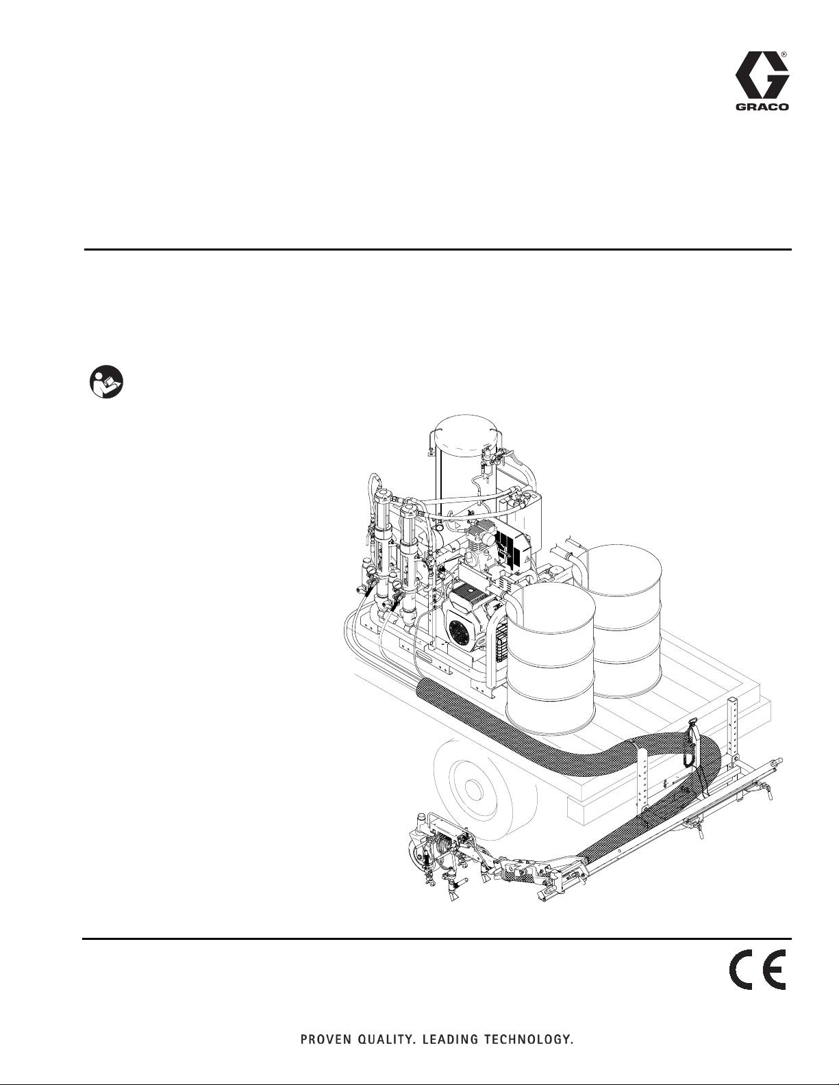
RoadLazer™ RoadPak™
Line Striping System
- For the Application of Road Marking and Reflective Coatings -
- For Professional Use Only -
2900 psi (20 MPa, 200 bar) Maximum Working Pressure
Important Safety Instructions
Read all warnings and instructions in this
manual. Save these instructions.
3A1696C
EN
ti15835a
Page 2

Table of Contents
Table of Contents
Warnings . . . . . . . . . . . . . . . . . . . . . . . . . . . . . . . . . 3
Component Identification . . . . . . . . . . . . . . . . . . . . 5
Component Function . . . . . . . . . . . . . . . . . . . . . . . 6
Pressure Relief Procedures . . . . . . . . . . . . . . . . . . 7
Changing Hydraulic Oil . . . . . . . . . . . . . . . . . . . . . . 8
Drain Oil . . . . . . . . . . . . . . . . . . . . . . . . . . . . . . . 8
Refilling Oil . . . . . . . . . . . . . . . . . . . . . . . . . . . . . 8
Compressor Belt and Hydraulic Pump Belt . . . . . 9
Belt Removal . . . . . . . . . . . . . . . . . . . . . . . . . . . . 9
Belt Installation . . . . . . . . . . . . . . . . . . . . . . . . . 10
Hydraulic Pump Replacement . . . . . . . . . . . . . . . 12
Removal . . . . . . . . . . . . . . . . . . . . . . . . . . . . . . 12
Installation . . . . . . . . . . . . . . . . . . . . . . . . . . . . . 13
Compressor Replacement . . . . . . . . . . . . . . . . . . 14
Removal . . . . . . . . . . . . . . . . . . . . . . . . . . . . . . 14
Installation . . . . . . . . . . . . . . . . . . . . . . . . . . . . . 15
Engine Replacement . . . . . . . . . . . . . . . . . . . . . . . 16
Engine Removal . . . . . . . . . . . . . . . . . . . . . . . . 16
Engine Installation . . . . . . . . . . . . . . . . . . . . . . . 17
Junction Box Circuit Board Replacement . . . . . . 18
Troubleshooting . . . . . . . . . . . . . . . . . . . . . . . . . . . 19
Wiring Diagrams . . . . . . . . . . . . . . . . . . . . . . . . . . 25
Schematics - 24F472, Controller . . . . . . . . . . . . 25
Schematics -16G161, Cable, Gun Arm . . . . . . . 26
Schematics - 16G049, Valve Air Solenoid . . . . . 27
Graco Standard Warranty . . . . . . . . . . . . . . . . . . . 28
2 3A1696C
Page 3
Warnings
Warnings
The following warnings are for the setup, use, grounding, maintenance, and repair of this equipment. The exclamation point symbol alerts you to a general warning and the hazard symbols refer to procedure-specific risks. When
these symbols appear in the body of this manual, refer back to these Warnings. Product-specific hazard symbols and
warnings not covered in this section may appear throughout the body of this manual where applicable.
WARNING
WARNINGWARNINGWARNING
FIRE AND EXPLOSION HAZARD
Flammable fumes, such as solvent and paint fumes, in work area can ignite or explode. To help prevent fire
and explosion:
• Use equipment only in well ventilated area.
• Do not fill fuel tank while engine is running or hot; shut off engine and let it cool. Fuel is flammable and can
ignite or explode if spilled on hot surface.
• Eliminate all ignition sources; such as pilot lights, cigarettes, portable electric lamps, and plastic drop cloths
(potential static arc).
• Keep work area free of debris, including solvent, rags and gasoline.
• Do not plug or unplug power cords, or turn power or light switches on or off when flammable fumes are
present.
• Ground all equipment in the work area. See Grounding instructions.
• Use only grounded hoses.
• Hold gun firmly to side of grounded pail when triggering into pail.
• If there is static sparking or you feel a shock, stop operation immediately. Do not use equipment until you
identify and correct the problem.
• Keep a working fire extinguisher in the work area.
SKIN INJECTION HAZARD
High-pressure fluid from dispensing device, hose leaks, or ruptured components will pierce skin. This may look
like just a cut, but it is a serious injury that can result in amputation. Get immediate SURGICAL TREATMENT.
• Keep clear of fluid outlet and leaks.
+
• Use guns, hoses and other components with pressure ratings equal to or higher than the pump rating.
• Follow the Pressure Relief Procedure before servicing or cleaning.
• Do not point dispensing device at anyone or at any part of the body.
• Do not stop or deflect leaks with your hand, body, glove, or rag.
• Tighten all fluid connections before operating the equipment.
• Check hoses and couplings daily. Replace worn or damaged parts immediately.
MOVING PARTS HAZARD
Moving parts can pinch, cut or amputate fingers and other body parts.
• Keep clear of moving parts.
• Do not operate equipment with protective guards or covers removed.
• Pressurized equipment can start without warning. Before checking, moving, or servicing equipment, follow
the Pressure Relief Procedure and disconnect all power sources.
3A1696C 3
Page 4
Warnings
WARNING
WARNINGWARNINGWARNING
EQUIPMENT MISUSE HAZARD
Misuse can cause death or serious injury.
• Do not operate the unit when fatigued or under the influence of drugs or alcohol.
• Do not exceed the maximum working pressure or temperature rating of the lowest rated system component.
See Technical Data in all equipment manuals.
• Use fluids and solvents that are compatible with equipment wetted parts. See Technical Data in all
equipment manuals. Read fluid and solvent manufacturer’s warnings. For complete information about your
material, request MSDS from distributor or retailer.
• Do not leave the work area while equipment is energized or under pressure. Turn off all equipment and
follow the Pressure Relief Procedure when equipment is not in use.
• Check equipment daily. Repair or replace worn or damaged parts immediately with genuine manufacturer’s
replacement parts only.
• Do not alter or modify equipment.
• Use equipment only for its intended purpose. Call your distributor for information.
• Route hoses and cables away from traffic areas, sharp edges, moving parts, and hot surfaces.
• Do not kink or over bend hoses or use hoses to pull equipment.
• Keep children and animals away from work area.
• Comply with all applicable safety regulations.
CARBON MONOXIDE HAZARD
Exhaust contains poisonous carbon monoxide, which is colorless and odorless. Breathing carbon monoxide
can cause death.
• Do not operate in an enclosed area.
TOXIC FLUID OR FUMES HAZARD
Toxic fluids or fumes can cause serious injury or death if splashed in the eyes or on skin, inhaled, or swallowed.
• Read MSDSs to know the specific hazards of the fluids you are using.
• Store hazardous fluid in approved containers, and dispose of it according to applicable guidelines.
BURN HAZARD
Equipment surfaces and fluid that’s heated can become very hot during operation. To avoid severe burns:
• Do not touch hot fluid or equipment.
PERSONAL PROTECTIVE EQUIPMENT
You must wear appropriate protective equipment when operating, servicing, or when in the operating area of
the equipment to help protect you from serious injury, including eye injury, hearing loss, inhalation of toxic
fumes, and burns. This equipment includes but is not limited to:
• Protective eyewear, and hearing protection.
• Respirators, protective clothing, and gloves as recommended by the fluid and solvent manufacturer.
CALIFORNIA PROPOSITION 65
The engine exhaust from this product contains a chemical known to the State of California to cause
cancer, birth defects or other reproductive harm.
4 3A1696C
Page 5
Component Identification
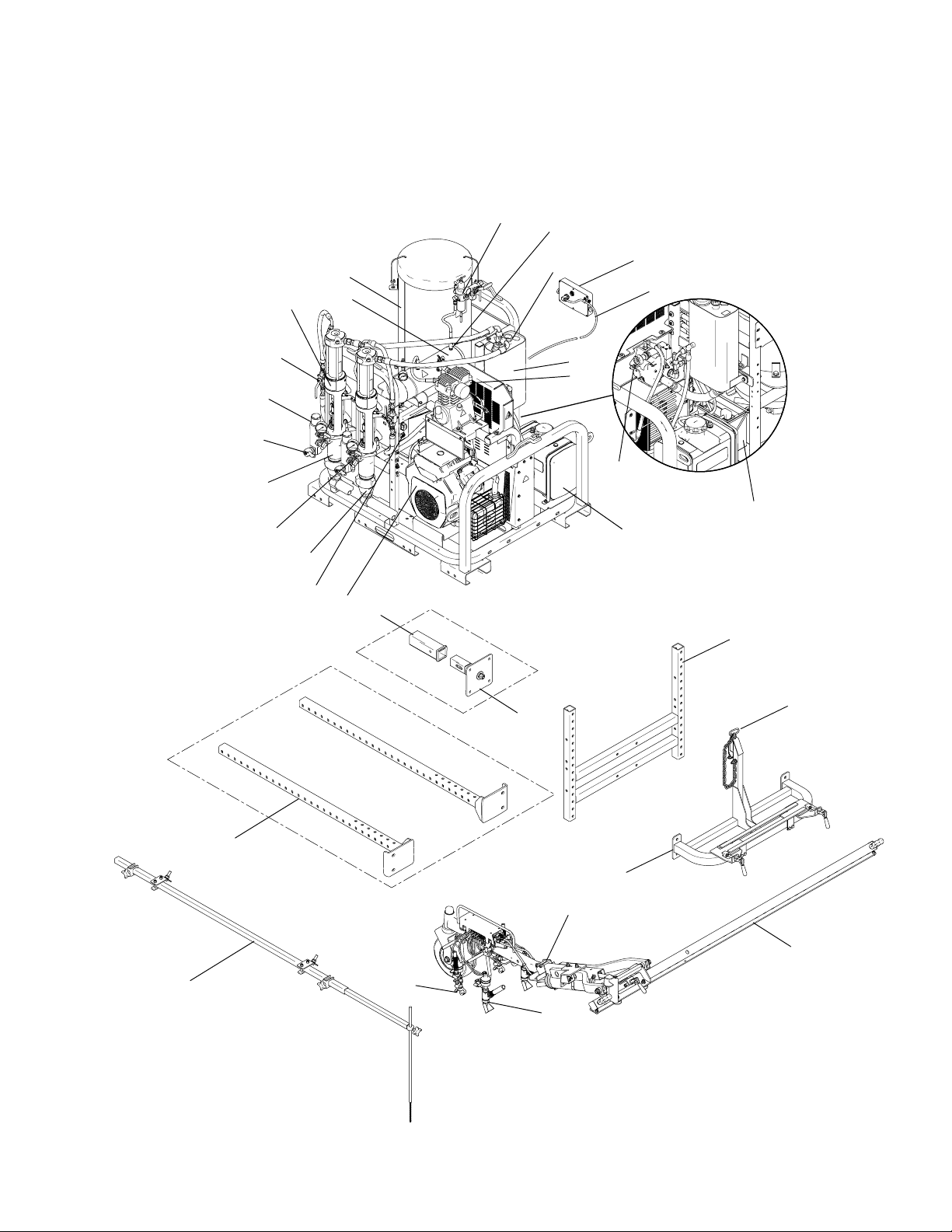
Component Identification
F
AC
D
A
C
L
K
G
AH
V
P
Y
A
AG
E
M
N
H
AD
Q
W
U
AA
AF
AE
Z
AB
R
T
S
ti15836a
B
J
3A1696C 5
Page 6

Component Function
Component Function
RPS 2900 Hydraulic Pump Provides fluid to be sprayed through the spray gun
A
Stow Bracket Pin Secures the spray gun boom arm when the RoadLazer is in transport mode
B
Fluid Outlet Supplies fluid from the displacement pump to the spray gun
C
Fluid Filter Filters fluid between the fluid source and the spray gun
D
Breather Cap Provides a means for hydraulic reservoir ventilation, oil check, and fill
E
Pressure Drain Valve Relieves Fluid Pressure when open
F
Fluid Inlet Displacement Pump entry for fluid from the paint drums (paint drums not shown)
G
Hydraulic Reservoir Holds 4 gallons (15.1 liters) of hydraulic oil for the hydraulic pump
H
Slide Beam Supports the spray gun boom arm
J
Bead Tank
K
Air Regulator Allows regulation of the bead tank air pressure
L
Programmable Skipline Controller Allows the user to program the operation of the RoadLazer
M
I/O Cable Carries electronic control signals from the Controller to the RoadLazer
N
18 HP Engine Powers the hydraulic pump and the air compressor
P
Hydraulic Pressure Control Knob Provides adjustment of hydraulic pressure (clockwise increases pressure)
Q
Spray Gun Boom Arm Allows striping on either side of the vehicle at adjustable distances
R
Bead Spray Gun Sprays beads when commanded by the Controller
S
Paint Spray Gun Sprays fluid when controller by the Controller
T
Fuel Tank Holds 6 gallons (23 liters) of gasoline
U
Air Accumulator Tank Helps reduce air temperature from compressor and increases pop-off valve life
V
Battery Provides power to start the Engine and Control Box
W
2 in. Hitch Receiver (not provided) Needed to hook-up the gun arm to the back of a truck
Y
Hitch Insert Allows the user to connect the gun arm to a single hitch vehicle
Z
Mounting Bracket Allows the user to connect the gun arm mount to the optimum height
AA
Gun Arm Mount Supports the main beam and the gun arm
AB
Hydraulic Valve Valve to shut off/on the hydraulic fluid to the hydraulic motor
AC
Compressor Provides an air supply for the solenoids and pressurizes the bead tanks
AD
Slide in Mounting Frame Allows user to connect the gun arm to the RoadPak frame
AE
RoadPak Pointer System Allows the user an alignment tool
AF
Air Pressure Quick Release Allows the user to use pressurized air
AG
Electrical Junction Box Allows the user access to electrical system
AH
Holds up to 38 gallons of reflective materials or element for single or double drop
beading
6 3A1696C
Page 7
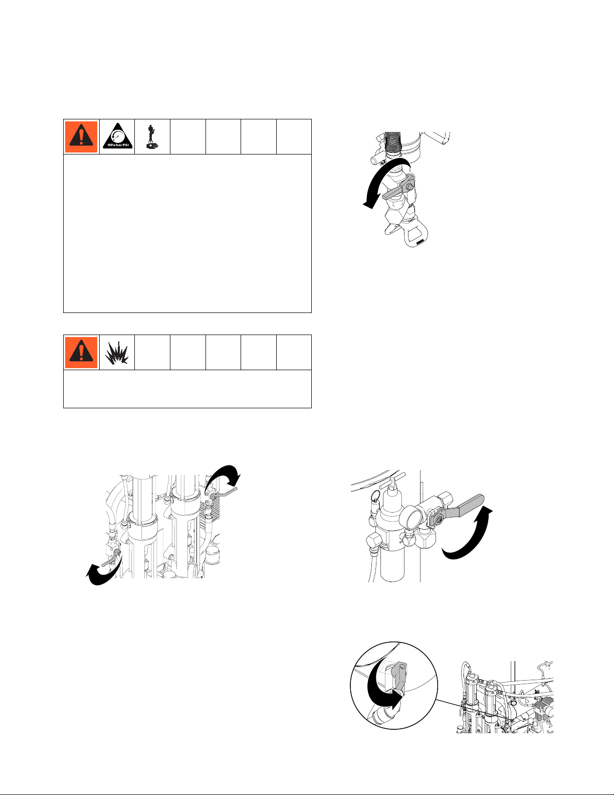
Pressure Relief Procedures
INJECTION HAZARD
The system pressure must be manually relieved to prevent the system from starting or spraying accidentally.
Fluid under high pressure can be injected through the
skin and cause serious injury. To reduce the risk of an
injury from injection, splashing fluid, or moving parts,
follow the Pressure Relief Procedure whenever you:
• are instructed to relieve the pressure
• stop spraying
• check or service any of the system equipment
• install or clean the spray tip
Pressure Relief Procedures
5. Close paint gun ball valves.
ti15953a
6. Open all drain valves, one at a time.
7. Close valves immediately to prevent paint from drying in system.
8. Shut off engine.
FIRE AND EXPLOSION HAZARD
When Flushing system, always connect grounding
cord.
RPS 2900 Pump Fluid Pressure Relief
1. Set hydraulic valve to OFF position.
ti15838a
2. Run engine at half throttle.
3. Place empty pail under paint guns to catch drainage.
NOTE: If you suspect that the spray gun or hose is completely clogged, or that pressure has not been fully
relieved after following the steps above, very slowly
loosen the hose end coupling, and relieve pressure
gradually. Then loosen it completely. Then clear the
valve or hose.
Bead System Pressure Relief
1. Relieve air pressure in bead tank by turning bead
system valve to OFF position.
ti16550a
Air System Pressure Relief
1. Relieve air pressure in air tank by turning air valve
to OPEN position.
4. Relieve hose pressure through guns. Use Programmable Skipline Controller to trigger each gun for at
least 3 seconds each.
NOTE: Always relieve pressure with the guns--not
with the filter drain valves.
ti16961a
3A1696C 7
Page 8
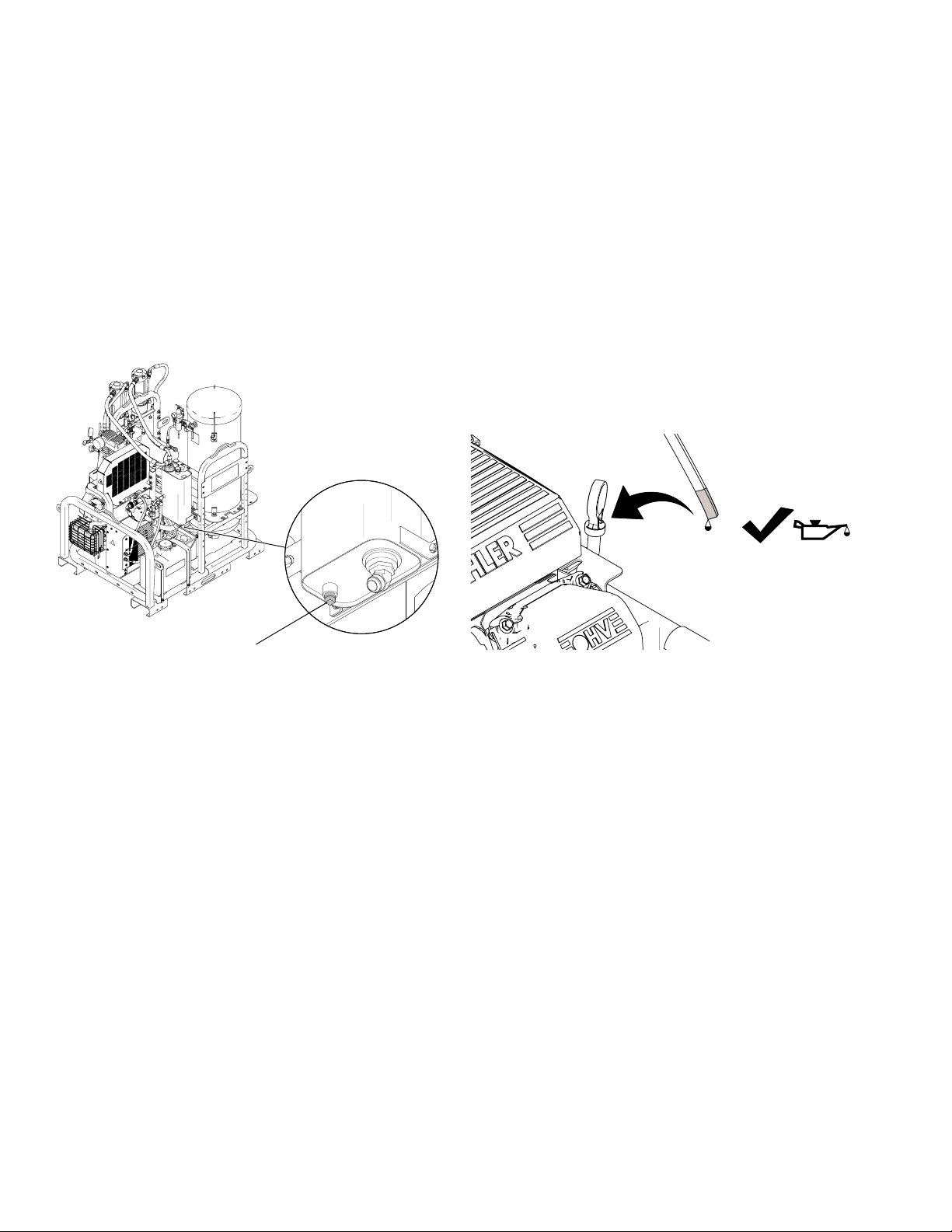
Changing Hydraulic Oil
Changing Hydraulic Oil
Drain Oil
1. Use a funnel to drain oil into a drain pan. If a funnel
is not available, remove the gas tank and place a
drain pan under the oil tank.
2. Unscrew reservoir drain plug (126e) and drain oil
from reservoir.
126e
ti16781a
Refilling Oil
1. Replace drain plug (126e).
2. Fill tank with Graco hydraulic oil, ISO 46.
NOTE: Tank holds approximately 4 gallons. Check
dipstick to ensure oil level is at an acceptable level.
3. Replace gas tank if removed.
4. Run the unit and recheck hydraulic oil level. Add oil
if necessary.
(cold)
ti16447a
8 3A1696C
Page 9
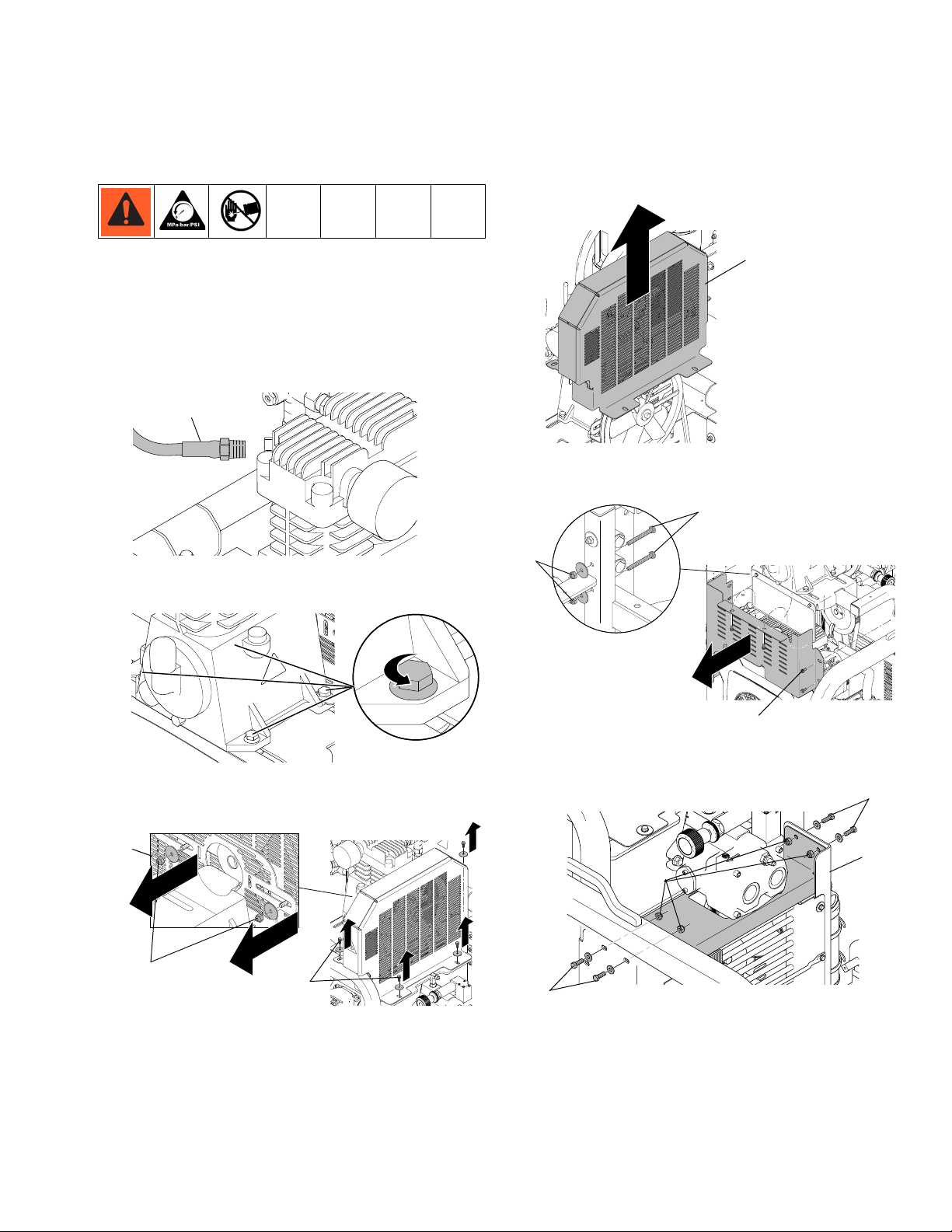
Compressor Belt and Hydraulic Pump Belt
Compressor Belt and Hydraulic Pump Belt
4. Remove top belt guard (108).
Belt Removal
NOTE: In order to remove the compressor belt, the
hydraulic pump belt must first be removed.
1. Remove air line (145) from compressor.
145
5. Remove three screws (1) and two nuts (15) and
bolts (22) from front belt guard.
22
108
ti16821a
ti17366a
2. Loosen four mounting bolts on compressor to
reduce compressor belt tension.
ti17364a
3. Remove four screws (1) and two nuts (15) from top
belt guard (108).
108
15
ti16822a
1
15
ti16820a
1
6. Remove four nuts (15) and bolts (14) from top fan
guard (104) and remove guard.
15
104
14
15
ti17367a
3A1696C 9
Page 10

Compressor Belt and Hydraulic Pump Belt
7. Remove eight screws from side guard (105) and
remove guard.
105
ti17368a
8. Remove two screws from engine muffler bracket.
Belt Installation
1. Install new compressor belt (102) if necessary.
102
ti17362a
2. Install hydraulic pump belt (103).
ti17361a
9. Loosen four nuts (5) and bolts (3) which secure
engine to relieve tension on hydraulic pump belt.
3
5
ti17365a
10. Tilt engine back and remove hydraulic pump belt
(103). Loop belt around the cooling fan.
11. If installing a new compressor belt, remove compressor belt (102).
103
ti17363a
3. Make sure compressor belt (102) is looped around
the engine groove, idler pulley and compressor pulley.
102
ti17362a
10 3A1696C
Page 11

Compressor Belt and Hydraulic Pump Belt
4. Visually inspect and make sure belts will be properly
lined up when engine is tightened.
5. Tighten four nuts (5) and bolts (3) to secure engine
in place. Visually inspect and make sure hydraulic
belt is properly aligned. Repeat until proper alignment is achieved.
3
5
ti17365a
6. Tighten four nuts (5) and bolts (12) so compressor
is fairly level. Before completely tightening bolts,
tension compressor belt (102) by shifting compressor to the right.
9. Install side guard (105) by tightening eight screws.
105
ti17368a
10. Install top fan guard (104) by tightening four bolts
(14) and nuts (15).
15
104
14
15
ti17367a
11. Install front belt guard (107) by tightening three
screws (1) and two nuts (15) and bolts (22).
ti17370a
7. Tighten four nuts (5) and bolts (12) to secure compressor in place.
ti17370a
ti17370a
8. Install two screws securing muffler bracket to
engine.
22
15
107
ti16828a
ti16828a
12. Install top belt guard (108) by tightening four screws
(1) and two nuts (15).
1
ti16829a
1
108
13. Install the air line (145) to the compressor.
145
ti17361a
ti17366a
3A1696C 11
Page 12

Hydraulic Pump Replacement
Hydraulic Pump Replacement
7. Remove nuts (13) and bolts (12) from pump frame.
Removal
1. Perform Pressure Relief Procedures, page 7.
2. Drain and Change Hydraulic Oil, page 8.
13
3. Remove hydraulic pump belt, see Compressor
Belt and Hydraulic Pump Belt Removal, page 9.
4. Unscrew suction line connections to hydraulic
pump. Place a container under hoses to catch any
dripping oil.
ti16823a
5. Loosen set screws (97) on front of large pulley (96).
97
96
ti16826a
12
8. Remove hydraulic pump (95).
95
ti16825a
9. Remove fittings (115, 116, 127) from pump (95) and
set aside to use on the new pump.
116
95
127
ti16818a
6. Remove pulley (96) from hydraulic pump shaft.
Remove idler pulley (101) if necessary.
115
ti16827a
96
ti16824a
12 3A1696C
Page 13

Installation
Hydraulic Pump Replacement
1. Install fittings (115, 116, 127) from old pump onto
new pump. Torque fittings (116, 127) to 600 +/1 10
in-lb (67.8 N•m). Torque fitting (115) to 450 in-lb
(50.8 N•m)
116
95
127
115
ti16827a
NOTE: Fill pump casing with hydraulic oil before
installing fitting (115).
2. Install new pump (95) to frame.
3. Install bolts (12) and nuts (13). Torque to 225 +/- 10
in-lb (25.42 N•m).
4. Replace large pulley (96) on hydraulic pump shaft.
97
96
ti16831a
5. Align pulley (96) on shaft.
6. Replace set-screw (97). Tighten and torque to 60
+/- 2 in-lb (6.8 +/- 0.2 N•m).
7. Install compressor belt (102) first, then install
hydraulic pump belt (103)hydraulic pump belt
(103)(see Compressor Belt and Hydraulic Pump
Belt Installation, page 9).
8. Install hydraulic fluid lines to the hydraulic pump and
tighten fittings.
9. Refill Hydraulic Supply System, see page 8.
3A1696C 13
Page 14

Compressor Replacement
Compressor Replacement
5. Remove top belt guard (108).
Removal
1. Perform Pressure Relief Procedures, page 7.
2. Remove are line (145) from compressor.
145
ti17366a
3. Remove four screws (1) and two nuts (15) securing
top belt guard (108).
108
ti16821a
6. Remove belt from compressor pulley. If belts needs
to be replaced, see Compressor Belt and Hydrau-
lic Pump Belt Replacement, page 9.
7. Unscrew relief valve assembly from the old compressor.
15
1
108
ti16822a
4. Loosen four mounting bolts on compressor to
reduce compressor belt tension.
ti17364a
ti17369a
14 3A1696C
Page 15

Compressor Replacement
Installation
1. Apply high temperature thread sealant to threads of
relief valve and screw in relief valve to new air compressor.
ti17378a
2. Hand-tighten four bolts (12) and nuts (5) to hold
compressor (100) and belt guard (101) to frame.
5. Tighten four nuts (5) and bolts (12) to secure compressor.
6. Install top belt guard (108) by tightening four screws
(1) and two nuts (15).
12
108
ti16829a
7. Install air line (145) to compressor.
145
ti17370a
3. Loop compressor belt (102) onto idler pulley, engine
pulley, and compressor pulley. NOTE: Make sure
belt is in the proper track.
4. Tighten four nuts (5) and bolts (12) so that compressor is fairly level. Before completely tightening the
bolts, tension compressor belt (102) by shifting
compressor to the right.
ti17366a
ti17486a
3A1696C 15
Page 16

Engine Replacement
Engine Replacement
Engine Removal
1. Perform Pressure Relief Procedure, page 7.
2. Disconnect ground terminal of battery, then disconnect the positive terminal.
3. Disconnect white and yellow electrical wires located
behind muffler.
83
6. Remove belts, see Compressor Belt and Hydrau-
lic Pump Belt Replacement, page 9.
7. Remove four bolts (3) from the engine (which will
also disconnect the ground wire).
3
ti17384a
8. Use a lift ring to lift and turn the engine (83) to
remove it from the frame. See engine manual for lift
locations.
ti17381a
4. Disconnect the positive red wire (90) attached to the
engine.
ti17380a
90
5. Disconnect gas line (260) and the evaporation line
(261) from the engine.
Pulley Removal
1. Loosen set screw (21) located on the side of the
pulley.
21
ti17382a
2. Remove bolt (19) in the center of pulley.
260
ti17383a
19
ti17379a
16 3A1696C
3. Remove pulley from engine
Page 17

Engine Replacement
Pulley Installation
1. Position new pulley on engine.
2. Install bolt (19), washer (4), and lock washer (20) in
center of pulley. Torque to 125 +/- 10 in-lb (14.1 +/-
1.1 N•m).
3. Tighten set screw (21). Torque to 60 +/- 2 in-lb (25.4
N•m).
Engine Installation
1. Use a lift ring to turn the engine and insert it into the
frame.
2. Connect ground wire and hand-tighten four bolts (3)
into engine.
5. Connect positive red wire (90) to engine.
ti17380a
90
6. Connect yellow and white electrical wires behind
muffler.
ti17381a
3
ti17384a
3. Replace belts, see Compressor Belt and Hydrau-
lic Pump Belt Replacement, page 9.
4. Connect evaporation line (261) and connect gas line
(260).
260
ti17379a
7. Connect positive terminal of battery, then connect
ground terminal.
3A1696C 17
Page 18

Junction Box Circuit Board Replacement
Junction Box Circuit Board Replacement
7. Remove circuit board (178) from junction box (179).
Installation
Removal
1. Disconnect ground terminal of battery and then disconnect positive terminal of battery.
2. Remove red and black wires from battery area.
3. Unplug control cable and gun arm cable from junction box (179).
179
ti17387a
4. Disconnect pump counter wires.
1. Insert circuit board (178) into junction box (179).
2. Replace four screws (38) and two screws (37) to
secure circuit board to junction box (179).
179
37
ti17386a
3. Reconnect pump counter wires and engine wires.
4. Plug in control cable and gun arm cable.
179
ti17388a
ti17385a
NOTE: Make sure control cable and gun arm cable
have proper strain relief to prevent damage to con-
5. Disconnect white and yellow wires behind engine
nections.
muffler.
5. When all maintenance is finished, reattach battery
connections.
ti17381a
6. Remove four screws (38) and two screws (37) from
junction box (179).
179
37
ti17485a
ti17386a
18 3A1696C
Page 19

Troubleshooting
Before you proceed with Troubleshooting, perform Pressure Relief Procedure, page 7.
Check everything in the troubleshooting tables before you disassemble any equipment.
Paint Guns and Bead Guns
PROBLEM CAUSE SOLUTION
Paint guns not spraying Clogged tips Clean tips
Fuse (20A) is blown Check 20A fuse between engine and solenoid
air valve connector.
Gun arm safety switch Check to make sure connectors on gun arm
safety switch are properly attached. When
gun arm is in down position, measure 12V
across the switch terminals to ensure it is
working properly. Replace switch if necessary.
Air compressor and unloader valve 1. Turn toggle switch at top of unloader (148)
to horizontal. NOTE: Unloader bypasses
air when system pressure reaches
approximately 115-120 psi (8 bar).
2. Turn off bead tank air valve (184) to isolate system.
3. If no leaks, check paint gun actuation air
lines.
Paint gun actuation airline 1. Remove actuation air lines from paint gun.
2. Trigger skipline controller.
3. If air flows from airline, repair paint gun
(manual 308613). If air does not flow,
check solenoid valves.
Solenoid valves 1. Go to diagnostic screen and check to see
if all solenoids are being recognized by
RoadPak Skipline Controller (manual
3A1215).
2. Remove solenoid valve cover (519).
3. Check for broken wiring or a damaged
plug (see Wiring Diagram, page 25).
4. Check for 12V DC between red wire and
ground.
Programmable Skipline Controller 1. Go to diagnostic screen and make sure all
switches are properly working (manual
3A1215).
2. Inspect wiring and plugs for damage.
3. Replace any damaged wiring or plugs
(manual 3A1301).
Troubleshooting
3A1696C 19
Page 20

Troubleshooting
PROBLEM CAUSE SOLUTION
Bead guns not spraying Paint guns and bead guns If paint guns and bead guns are not working,
check paint guns first.
Bead tank air valve Turn bead tank valve ON
Nozzles plugged 1. Turn off air pressure.
2. Remove nozzles and clean out any plugging.
3. If paper or other debris is constantly plugging nozzles use a filter when loading
bead tank (standard window screen works
fine).
4. With nozzles removed, apply air to bead
tank. Spray beads into dry container.
5. Check if beads are wet. If beads are wet,
remove beads from bead tank and replace
with dry beads.
Solenoid valves 1. Go to diagnostic screen and check to see
if all solenoids are being recognized by
RoadPak Skipline Controller (manual
3A1215).
2. Remove solenoid valve cover (590).
3. Check for broken wiring or a damaged
plug (see Wiring Diagram, page 25).
4. Check for 12V DC between red wire and
ground.
Programmable Skipline Controller 1. Go to diagnostic screen and make sure all
switches are properly working (manual
3A1215).
2. Inspect wiring and plugs for damage.
3. Replace any damaged wiring or plugs
(manual 3A1301).
Actual line length not matching programmed line length
Actual cycle not matching programmed
cycle
Bead guns not synchronizing with
paint guns
Out of calibration 1. Follow calibration in Programmable Skip-
line Controller manual 3A1215.
2. Spray one or two test skips and measure
actual length. If actual length is longer
than programmed length, increase Paint
Gun ON delay. If actual length is shorter
than programmed length, increase Paint
Gun OFF delay.
Out of calibration Follow calibration procedure in Programmable
Skipline Controller manual 3A1215.
Out of calibration 1. Follow calibration in Programmable Skip-
line Controller manual 3A1215.
2. If beads start before paint, add delay time
to Bead ON Delay. If paint starts before
beads, add equal delay time to both Paint
ON and Paint OFF Delays (this does not
affect paint skip line length).
3. If beads end before paint, add delay time
to Bead OFF Delay. If beads end after
paint, add equal delay time to both Paint
ON, Paint OFF and Bead ON Delays. This
shifts everything forward.
20 3A1696C
Page 21

Troubleshooting
PROBLEM CAUSE SOLUTION
Paint guns not turning off immediately
or at all
Gun arm wobbling or hopping excessively
Excessive overspray on gun arm
wheel
Pulsation in spray pattern Low or erratic pressure in paint pump 1. Check paint supply and suction inlet
Valve needed 1. Spray needle with light coat of lubricant.
Use air hose or water hose to break up
and remove solidified beads.
2. Replace needle, seat, and packings (see
Repair Kit 238339).
Swivel nut Gun arm wobbles
1. Remove dust cap (547).
2. Tighten boom arm swivel nut (504) until
swivel has slight restriction.
Gun arm hops
1. Lower air pressure in gun arm wheel.
2. Replace damaged gas shock (507).
Paint guns out of position 1. Angle paint guns back 15° to 20°.
2. Coat wheel and gun arm parts with
non-stick cooking oil, light oil, silicon, or
Auto Mask ZEP to prevent paint from
sticking to them.
screens.
2. Replace spray tips.
3. Check outlet filter.
4. Replace packings. Clean and service
intake valve and piston valve.
3A1696C 21
Page 22

Troubleshooting
Programmable Skipline Controller
PROBLEM CAUSE SOLUTION
Controller not turning on Fuse, battery, or wiring
Controller shutting down or cutting out
during striping
System Delay not turning on System not configured for striping or is
Controller not displaying MPH (KM/H),
or readout is erratic
System Delay actual distance not precisely matching programmed distance
Battery or wiring
shut off
Gun arm sensor or sensor wiring
Programmed distance needs fine tuning
1. Check fuse located next to 12V
RoadLazer battery.
2. Check battery voltage. Replace if
necessary.
3. Inspect wiring at battery for corrosion. Inspect control cable for damage.
1. Check battery voltage. A weak battery can drop voltage low enough to
cause intermittent shut down.
2. Check wiring.
3. Ground control box to vehicle chassis.
1. Remove gun arm from stowed position, and start up engine. System
delay will not turn on unless you are
ready to stripe.
2. System Delay must be turned back
on after engine is turned off.
1. Check sensor (524) located on gun
arm wheel assembly. Set sensor
approximately 1/8 in. (3 mm) from
target plate.
2. Check sensor head for damage.
Replace if damaged.
3. Check sensor wiring by removing
solenoid valve cover (519).
1. This is usually true. Get it as close as
possible, then spray one additional
test line and try to hit the start point.
2. Measure difference between start
point and where paint guns turn on. If
paint guns turn on before start point,
add measured difference to current
system delay distance. If paint guns
turn on after start point, subtract
measured difference.
22 3A1696C
Page 23

Air and Bead System
PROBLEM CAUSE SOLUTION
Belts squealing during engine startup Compressor belt needs tightening or
replacing
Paint guns not spraying when empty
bead tank is empty
No system pressure Compressor bypassing air continuously
Beads not dispensing properly Excessive water or moisture in bead
All of air supplied by air compressor is
rushing out of bead gun nozzles. In turn,
system air pressure cannot build
enough to trigger guns. This is normal.
tank
Troubleshooting
See Air Compressor Belt Replacement, page 9.
Fill bead tank with beads or turn off air
supply to bead tank.
1. Make sure silver switch on top of
unloader valve (148) is turned horizontally.
2. Move silver switch on top of unloader
valve (148) up and down. This might
loosen a sticky valve.
3. Replace unloader valve (148).
1. Only pressurize reflective materials
when dispensing. Small air leaks at
gun nozzle or air fittings cause continuous moisture to be pumped into
tank.
Low system pressure Excessive air leaks
No beads dispensing Beads have solidified
2. For areas of extreme humidity a Bendix air dryer or equivalent may be
installed in air line bead tank. Typically when beads are used continuously, they do not spend enough
time in tank to collect enough moisture to be a problem. Usually it is
continuous stencil painting for long
periods of time with little bead consumption and high humidity that can
cause problems.
1. Fix all air leaks before they become
a problem. Air leaks can eventually
starve system air supply.
2. Most air leaks occur at bead tank
outlet fitting. If fitting leaks air, completely remove it and use thread tape
and liquid thread sealant before reinstalling it.
1. Never store RoadLazer with reflective materials in tank for long periods
of time.
2. Remove aluminum fitting from bottom of tank. Flush out solidified
beads.
3. Use air hose or water hose to break
up and remove solidified beads from
tank.
3A1696C 23
Page 24

Troubleshooting
Kohler Engine
PROBLEM CAUSE SOLUTION
Engine not starting Programmable Skipline Controller is
shut off, or engine is out of fuel
Engine stalling Engine fuel tank is empty or not breath-
ing, or engine oil is low.
Paint Pumps
PROBLEM SOLUTION
Pumps wearing prematurely
Reduce premature pump wear and costly down-time with the following tips:
• Keep piston throat full of TSL
• If possible, shorten lines to reduce pump back pressure
• Use Graco strainer at pump inlet to filter-out dried paint and debris
• Inspect internal suction hoses for paint build-up, which can cause pump starving
• Replace pump packings seasonally to increase piston and sleeve life
• Always keep hydraulic reservoir full to reduce heat build-up
1. Turn on Programmable Skipline Controller. Engine will not start with control off.
2. Check fuel supply.
3. See Kohler engine instruction manual.
1. Check fuel supply. Open breather on
fuel tank. Check engine oil level.
2. See Kohler engine instruction manual.
Paint and Paint Manufacturers
PROBLEM SOLUTION
Do not know what type of paint to use
When ordering paint from manufacturer:
• Inform paint suppliers of type of equipment to be used (RoadLazer), filter screen
• Require that paint must pass through a 30-mesh filter with minimal filter plugging
Things to know about waterborne paint and striping equipment:
• Flush waterborne paints from system if system is not used on a regular basis.
• Waterborne paints will not redissolve. Dried paint film in paint containers or paint
• Waterborne paints cannot freeze or tolerate temperatures above 120° F (49° C).
• With age, waterborne paint pigments settle to bottom of container. Never use set-
sizes (30 mesh) and tip sizes (33 to 45 thousands)
Waterborne paints do not dilute easily. Use warm soapy water to flush system.
suction lines must be removed. Graco offers a Suction Line Strainer Kit 24G774
that should be installed at least 2 ft from pump inlet to remove contamination.
Strainers must be cleaned regularly to avoid pump starving or cavitation.
Consult paint manufacturer.
tled paint without agitating. It is important to order fresh paint. Require paint manufacturers to supply manufactured dates and stagger shipments throughout striping
season.
24 3A1696C
Page 25

Wiring Diagrams
Schematics - 24F472, Controller
Control Cable Diagram for RoadPak System
Contact Description Action
1 12 VDC Supply Voltage
2 Leave Open- Do Not Connect
3 Leave Open- Do Not Connect
4 Sensor, pump (1) Input
5 Sensor, pump (2) Input
6 Paint Gun (1) Solenoid 1 Output (1 amp Max)
7 Paint Gun (2) Solenoid 3 Output (1 amp Max)
8 Paint Gun (3) Solenoid 5 Output (1 amp Max)
9 Bead Gun (1) Solenoid 2 Output (1 amp Max)
10 Bead Gun (2) Solenoid 4 Output (1 amp Max)
11 Bead Gun (3) Solenoid 6 Output (1 amp Max)
12 Engine Shutdown (ground)
13 Ground **
14 Ground **
15 Ground **
16 Sensor Distance Input
17 Ground **
18 Leave Open- Do Not Connect
Schematics - 24F922, BOARD,
Interconnect
Yellow +12 VDC Engine Auxiliary
White Engine Shutdown
+12 VDC Postive Battery
Negative battery
ABC
POWER
ON
OFF
PROGRAMMABLE
SKIPLINE CONTROL
ti16358a
24F469, Cable, Control
DEF
Wiring Diagrams
SYSTEM
DELAY
S
TART
SKIP
SPACE
BEADS ON
MENU
MENU
BEAD TEST
RESET
HOLD
1
4
3
8
7
12
13
16
1
4
3
8
7
12
13
16
9
9
17
17
2
5
6
10
11
15
14
18
2
5
6
10
11
15
14
18
20 AMP
4 AMP
24F922, BOARD,
Interconnect
PIN Description
1 Not Used
2 Pump Counter Signal
3 Pump Counter Ground
4 Pumper Counter Power +12 VDC
ti17509b
PIN Description
1 Paint Gun (1) Solenoid 1
2 Bead Gun (1) Solenoid 2
3 Paint Gun (2) Solenoid 3
4 Bead Gun (2) Solenoid 4
5 Paint Gun (3) Solenoid 5
6 Bead Gun (3) Solenoid 6
7 Wheel Sensor Signal
8 Wheel Sensor Ground
9 Wheel Sensor Power + 12 VDC
10 Solenoid Power + 12 VDC
12345
678910
3A1696C 25
Page 26

Wiring Diagrams
Schematics -16G161, Cable, Gun Arm
16G161, Cable, Gun Arm
16G161, Cable, Gun Arm
10 BLUE 8
6 ORANGE 6
5 WHITE/BLACK 5
4 RED/BLACK 4
3 WHITE 3
2 GREEN/BLACK 2
1 ORANGE/BLACK 1
19418-0024 & 19420-0002
FEMALE TERMINALS
9 RED
8 BLACK
7 GREEN
19418-0022 & 19420-0002
FEMALE TERMINALS
26 3A1696C
Page 27

Schematics - 16G049, Valve Air Solenoid
(
Wiring Diagrams
(Gun On)
(Gun Off)
16G049, Valve, Air Solenoid
123456
A
B
PIN Description
1 Wheel Sensor Power +12VDC
2 Wheel Sensor Ground
3 Wheel Sensor Signal
15E943, Senor Distance
123
16G049, Valve, Air Solenoid
8 RED (12vdc FROM BATTERY)
6 BLACK (GROUND SWITCHED AT CONTROLLER)
5 BLACK (GROUND SWITCHED AT CONTROLLER)
4 BLACK (GROUND SWITCHED AT CONTROLLER)
3 BLACK (GROUND SWITCHED AT CONTROLLER)
2 BLACK (GROUND SWITCHED AT CONTROLLER)
19435-0814 & 19417-0028
MALE TERMINALS
1 BLACK (GROUND SWITCHED AT CONTROLLER)
1
2
3
#1 RED (12vcd)
#2 BLACK (GRD)
#1 GREEN (SIGNAL +)
F-1/4” QC.
F-1/4” QC.
MAC VALVES
SOLENOID F BEAD 3
SOLENOID E BEAD 3
SOLENOID D BEAD 2
SOLENOID C BEAD 2
SOLENOID B BEAD 1
SOLENOID A BEAD 1
ARM-UP
SAFETY SWITCH
ti17511b
3A1696C 27
Page 28

Graco Standard Warranty
Graco warrants all equipment referenced in this document which is manufactured by Graco and bearing its name to be free from defects in
material and workmanship on the date of sale to the original purchaser for use. With the exception of any special, extended, or limited warranty
published by Graco, Graco will, for a period of twelve months from the date of sale, repair or replace any part of the equipment determined by
Graco to be defective. This warranty applies only when the equipment is installed, operated and maintained in accordance with Graco’s written
recommendations.
This warranty does not cover, and Graco shall not be liable for general wear and tear, or any malfunction, damage or wear caused by faulty
installation, misapplication, abrasion, corrosion, inadequate or improper maintenance, negligence, accident, tampering, or substitution of
non-Graco component parts. Nor shall Graco be liable for malfunction, damage or wear caused by the incompatibility of Graco equipment with
structures, accessories, equipment or materials not supplied by Graco, or the improper design, manufacture, installation, operation or
maintenance of structures, accessories, equipment or materials not supplied by Graco.
This warranty is conditioned upon the prepaid return of the equipment claimed to be defective to an authorized Graco distributor for verification of
the claimed defect. If the claimed defect is verified, Graco will repair or replace free of charge any defective parts. The equipment will be returned
to the original purchaser transportation prepaid. If inspection of the equipment does not disclose any defect in material or workmanship, repairs
will be made at a reasonable charge, which charges may include the costs of parts, labor, and transportation.
THIS WARRANTY IS EXCLUSIVE, AND IS IN LIEU OF ANY OTHER WARRANTIES, EXPRESS OR IMPLIED, INCLUDING BUT NOT
LIMITED TO WARRANTY OF MERCHANTABILITY OR WARRANTY OF FITNESS FOR A PARTICULAR PURPOSE.
Graco’s sole obligation and buyer’s sole remedy for any breach of warranty shall be as set forth above. The buyer agrees that no other remedy
(including, but not limited to, incidental or consequential damages for lost profits, lost sales, injury to person or property, or any other incidental or
consequential loss) shall be available. Any action for breach of warranty must be brought within two (2) years of the date of sale.
GRACO MAKES NO WARRANTY, AND DISCLAIMS ALL IMPLIED WARRANTIES OF MERCHANTABILITY AND FITNESS FOR A
PARTICULAR PURPOSE, IN CONNECTION WITH ACCESSORIES, EQUIPMENT, MATERIALS OR COMPONENTS SOLD BUT NOT
MANUFACTURED BY GRACO. These items sold, but not manufactured by Graco (such as electric motors, switches, hose, etc.), are subject to
the warranty, if any, of their manufacturer. Graco will provide purchaser with reasonable assistance in making any claim for breach of these
warranties.
In no event will Graco be liable for indirect, incidental, special or consequential damages resulting from Graco supplying equipment hereunder, or
the furnishing, performance, or use of any products or other goods sold hereto, whether due to a breach of contract, breach of warranty, the
negligence of Graco, or otherwise.
FOR GRACO CANADA CUSTOMERS
The Parties acknowledge that they have required that the present document, as well as all documents, notices and legal proceedings entered into,
given or instituted pursuant hereto or relating directly or indirectly hereto, be drawn up in English. Les parties reconnaissent avoir convenu que la
rédaction du présente document sera en Anglais, ainsi que tous documents, avis et procédures judiciaires exécutés, donnés ou intentés, à la suite
de ou en rapport, directement ou indirectement, avec les procédures concernées.
Graco Information
For the latest information about Graco products, visit www.graco.com.
TO PLACE AN ORDER, contact your Graco distributor or call 1-800-690-2894 to identify the nearest distributor.
All written and visual data contained in this document reflects the latest product information available at the time of publication.
GRACO INC. AND SUBSIDIARIES • P.O. BOX 1441 • MINNEAPOLIS MN 55440-1441 • USA
Copyright 2011, Graco Inc. All Graco manufacturing locations are registered to ISO 9001.
Graco reserves the right to make changes at any time without notice.
Original instructions. This manual contains English. MM 3A1696
Graco Headquarters: Minneapolis
International Offices: Belgium, China, Japan, Korea
www.graco.com
Revised November 2013
 Loading...