

Page 1
Instructions - Parts
HFR Flow Meter
3A1657F
Kits
For installation and calibration of flow meters on the HFR dispensing system. For
professional use only.
HFR: 3000 psi (21 MPa, 207 bar) Maximum Working Pressure
HFR For NVH: 2000 psi (14 MPa, 138 bar) Maximum Working Pressure
Important Safety Instructions
Read all warnings and instructions in the
HFR, Setup-Operation and NVH,
Setup-Operation manuals.
Save all instructions.
EN
ti17008a
Page 2
Contents
Contents
Contents . . . . . . . . . . . . . . . . . . . . . . . . . . . . . . . . . . 2
Kits . . . . . . . . . . . . . . . . . . . . . . . . . . . . . . . . . . . . . . 2
Related Manuals . . . . . . . . . . . . . . . . . . . . . . . . . . . 3
Overview . . . . . . . . . . . . . . . . . . . . . . . . . . . . . . . . . . 3
Installation . . . . . . . . . . . . . . . . . . . . . . . . . . . . . . . . 4
Calibration . . . . . . . . . . . . . . . . . . . . . . . . . . . . . . . 12
Flow Meter Connector Pinout . . . . . . . . . . . . . . . . 19
Maintenance . . . . . . . . . . . . . . . . . . . . . . . . . . . . . . 19
Parts . . . . . . . . . . . . . . . . . . . . . . . . . . . . . . . . . . . . 20
Technical Data . . . . . . . . . . . . . . . . . . . . . . . . . . . . 27
Graco Standard Warranty . . . . . . . . . . . . . . . . . . . 28
Kits
Flow Meter Electronics (Necessary)
Part No. Description
24J318 Flow Meter Electronics Kit
HFR: “A” and “B” Side Flow Meter (One for each
side)
Part No. Description
24J319 S3000 Flow Meter Kit
24J320 G3000 Flow Meter Kit
24J321 G3000HR Flow Meter Kit
24J322 HG6000 Flow Meter Kit
24J323 HG6000HR Flow Meter Kit
HFR for NVH: Flow Meter Kits
Part No. Description
24T182 24:1 and 16:1 NVH Cart
Flow Meter Kit
24T183 1:1 NVH Cart Flow Meter Kit
24T200 24:1 and 16:1 NVH Modular
Flow Meter Kit
24T201 1:1 NVH Modular Flow Meter Kit
HFR: Flow Meter Calibration Kit
(Per Applicator)
Part No. Description
24J324 L-Head Flow Meter Calibration Kit
24J325 S-Head Flow Meter Calibration Kit
24J326 P2 Flow Meter Calibration Kit
24J357 GX-16 Flow Meter Calibration Kit
24F227 EP/Fusion Flow Meter Calibration Kit
255247 MD2 1:1 Flow Meter Calibration Kit
255245 MD2 10:1 Flow Meter Calibration Kit
2 3A1657F
Page 3

Related Manuals
Related Manuals
Component manuals in English. Manuals are available
at www.graco.com.
Manual No. Description
Systems
313997 HFR Operation
313998 HFR Repair-Parts
3A2797 HFR for NVH Foam - Cart,
Setup-Operation
3A1961 HFR for NVH Foam - Modular,
Setup-Operation
Flow Meters
308778 3000 Series Flow Meters
309834 6000 Series Flow Meters
Dispense Valves
312753 L-Head Operation-Maintenance
312752 S-Head Operation-Maintenance
313536 GX-16 Operation
313872 EP Gun, Instructions-Parts
Overview
On HFR systems, the flow meters are used only as a
method of monitoring system performance, which will
help with system maintenance. The ratio displayed on
the ADM is a running average of the data collected.
NOTE: The flow meters will not correct any ratio errors
caused by system performance.
When the ratio monitoring system is active, the ratio will
be displayed on the screen below in the form of ratio:1
(e.g. 24.03:1). The display will show “--:--” when the ratio
monitoring system is not active. The recommended minimum value for an alarm is 3%.
NOTE: For circulation or NVH systems, the ratio monitoring system only becomes active when the machine is
in high pressure circulation.
313213 Probler P2, Instructions-Parts
309550 Fusion Gun Instructions-Parts
312185 MD2 Valve Instructions-Parts
313380 GX-7 DI Auto-Robotic Spray Gun,
Operation-Maintenance
Accessories
3A0395 HFR and VRM Tank Feed Systems
Instructions-Parts
3A0861 Ratio Check Assembly for Fusion/EP
Guns
3A1657F 3
Page 4
Installation
Installation
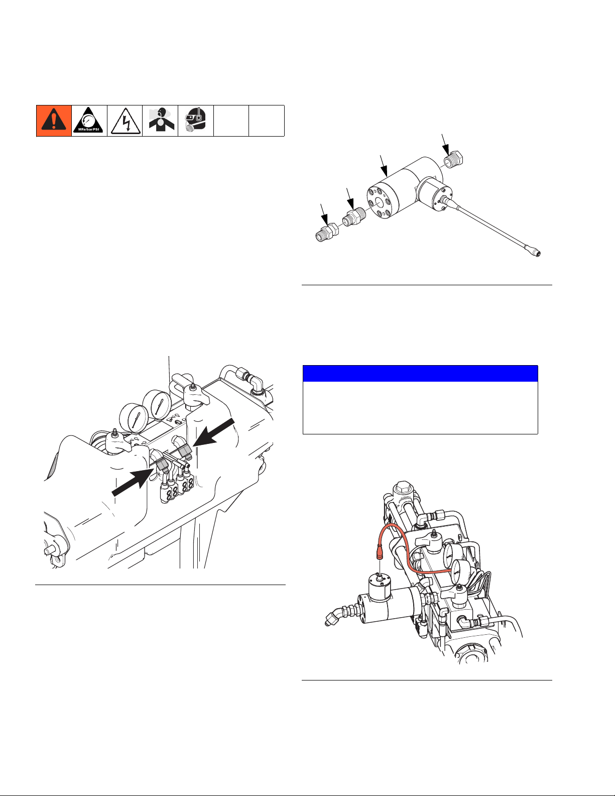
Flow Meter Electronics Kit 24J318
1. Perform Shutdown procedure. See HFR or NVH
operation manual for detailed instructions.
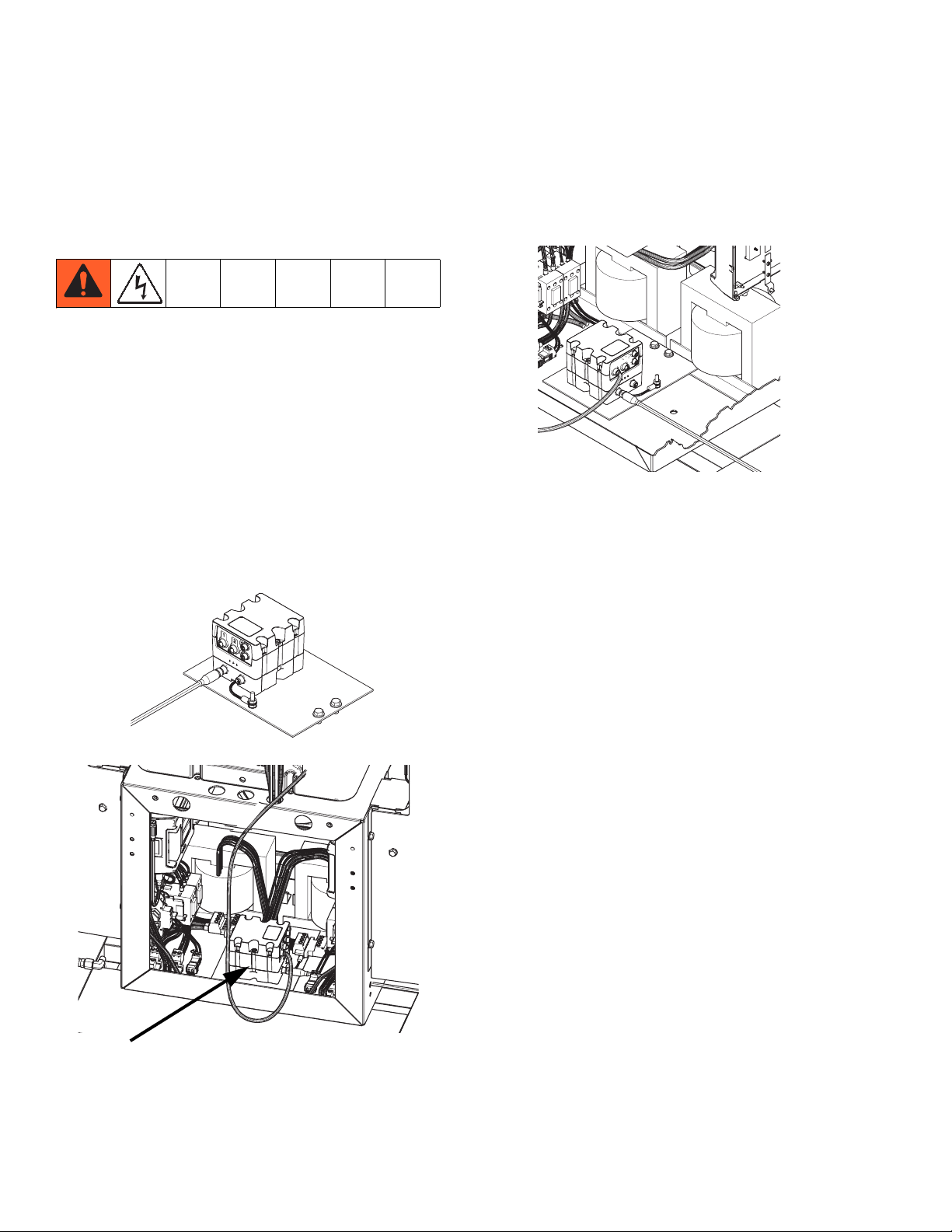
2. Use two 111800 hex head screws (supplied) to
mount electronics assembly 24J318 to the bottom of
the electrical enclosure. If there are transformers
installed, remove two of the hex head screws from
the transformers and use those two holes to mount
the electronics assembly and discard the supplied
hex head screws.
NOTE: For NVH machines, mount electronics assembly
to the bottom of the “B” side electrical enclosure.
3. Connect CAN cable to CAN connection labeled “1”
on the fluid control module.
ti17011a
4. Connect opposite end of the CAN cable (111) to any
free CAN port on any other fluid control module or
temperature control module in the system. If none
are available, use CAN cables (111 and 113) to connect to CAN splitter inside the power distribution
box. See references on page 20.
ti17009a
ti17010a
4 3A1657F
Page 5
Installation
HFR: 3000 Series Flow Meter
1. Perform HFR Pressure Relief Procedure. See
HFR operation manual for detailed instructions.
2. Perform dispense valve Pressure Relief Proce-
dure. See dispense valve manual, page 3, for
detailed instructions.
3. Verify all air, hydraulic, and material pressures have
been relieved before continuing.
4. Perform HFR Shutdown procedure. See HFR oper-
ation manual for detailed instructions.
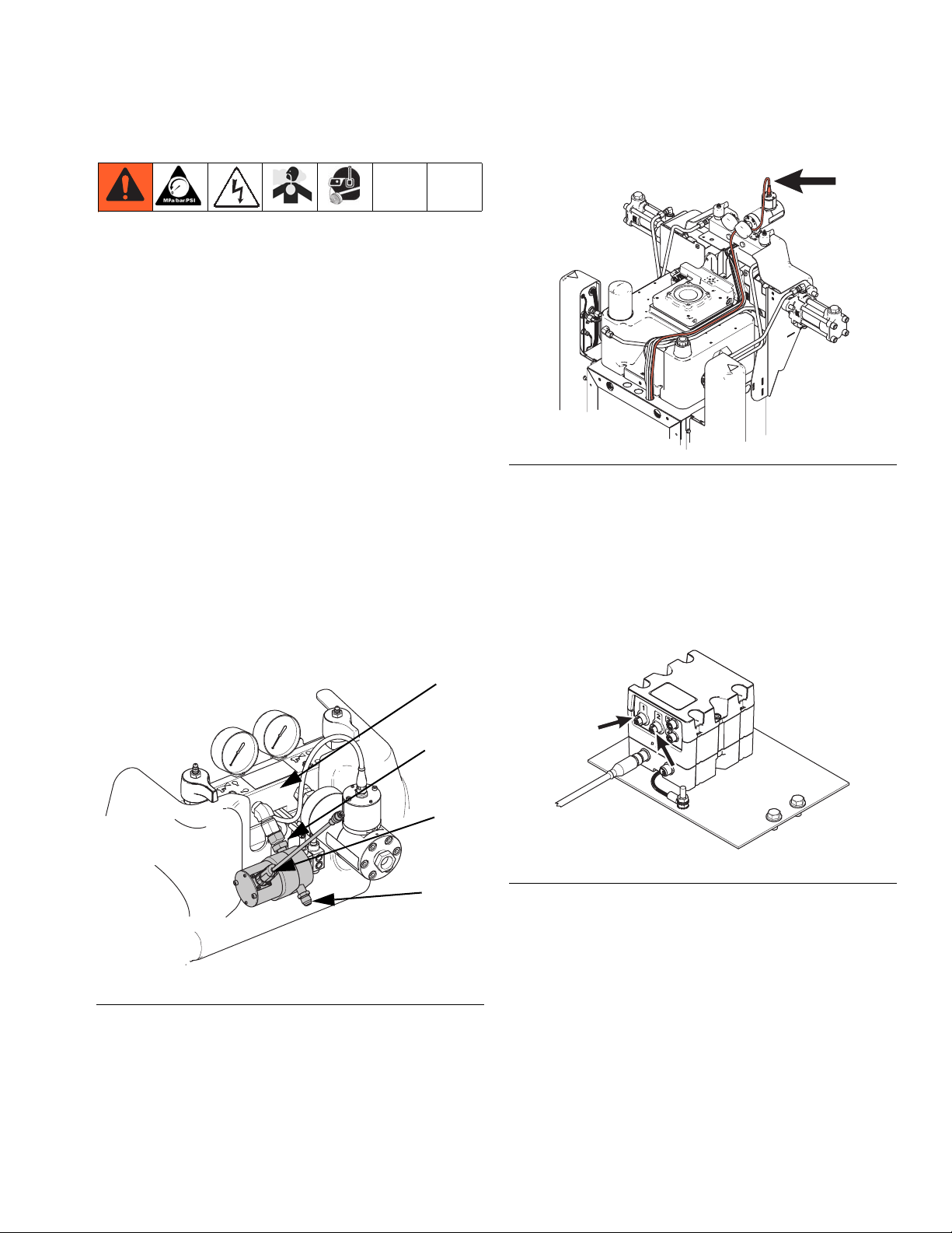
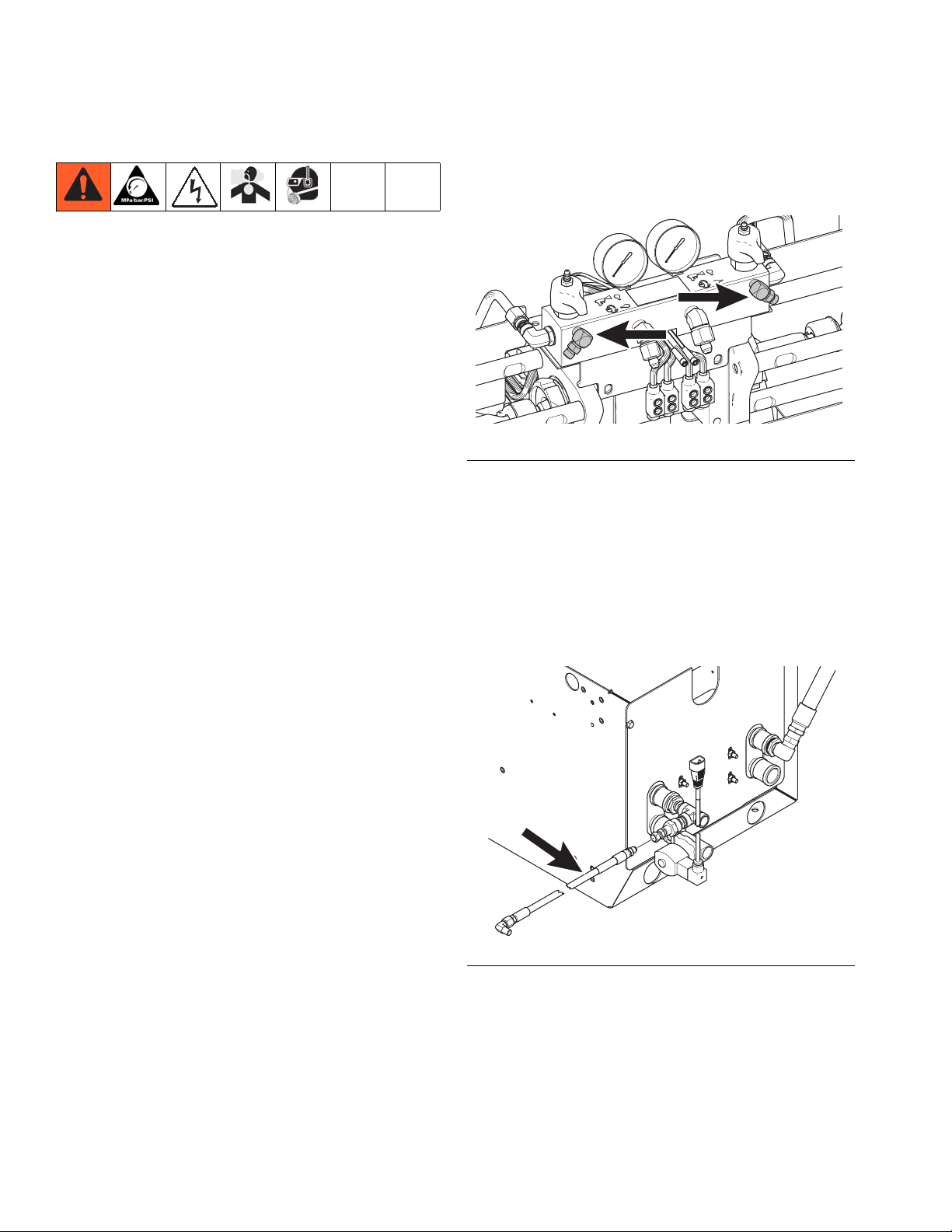
5. If the flow meter is for the A (Red) side, connect inlet
fitting (2) and outlet fitting (4) to the flow meter. See
F
IG. 1.
If the flow meter is for the B (Blue) side, connect
inlet fitting (3) and outlet fitting (5) to the flow meter.
See F
IG. 1.
NOTE: The connections for each side of the machine
are different sizes to prevent attaching the incorrect
hoses. The A (Red) side has the smaller connections.
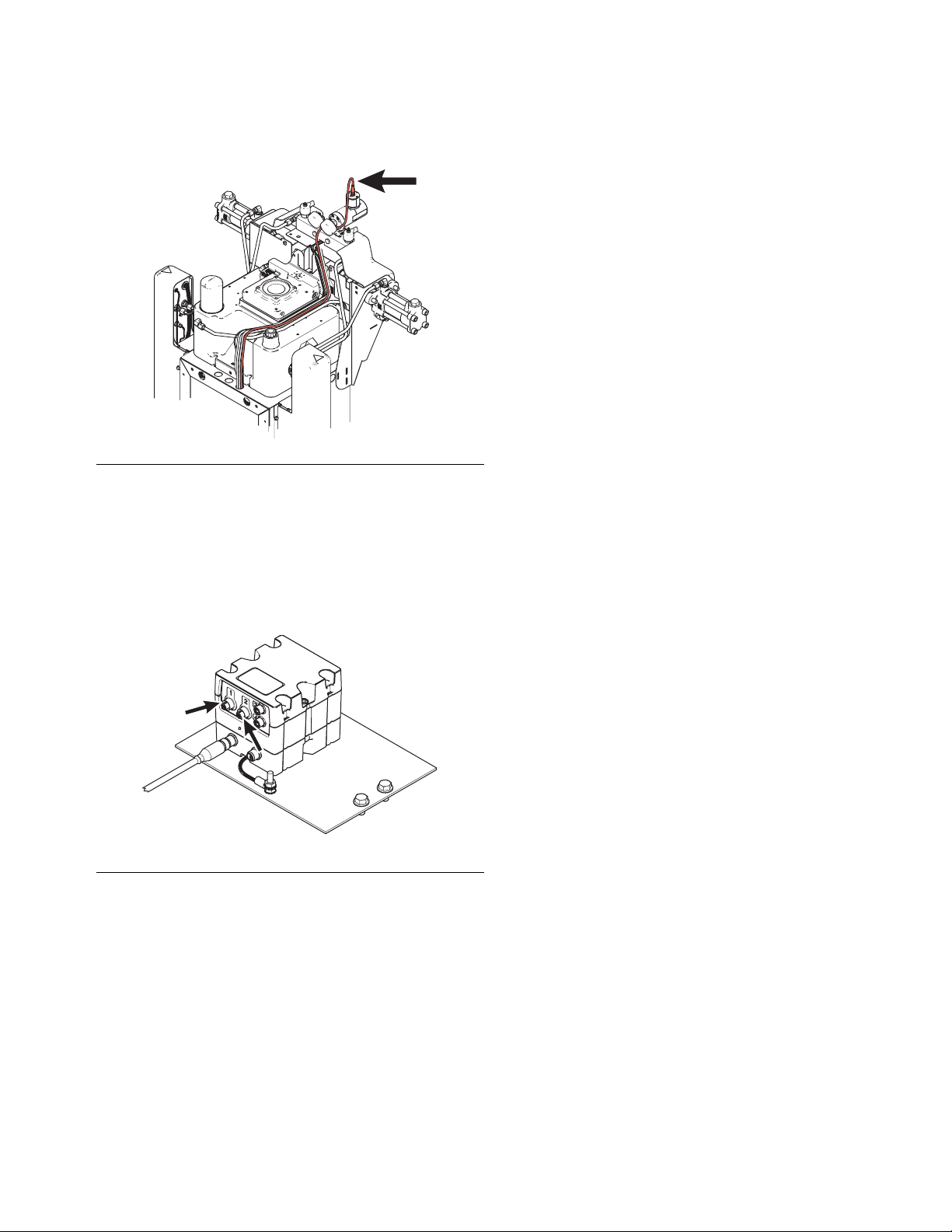
8. Route the flow meter data cable as shown in F
IG. 2.
ti17013a
FIG. 2: Flow Meter Data Cable Routing
9. Connect the other end of the flow meter data cable
to the fluid control module installed in the electrical
enclosure.
If the data cable is for the A (Red) side flow meter,
connect to port 1 on the FCM. See F
IG. 2.
If the data cable is for the B (Blue) side flow meter,
connect to port 2 on the FCM. See F
IG. 2.
A
2 or 3
B
4 or 5
ti17012a
FIG. 1: Flow Meter Installed on Fluid Manifold --
A (Red) side shown
6. Connect the flow meter assembly to the fluid
manifold (A) on the HFR system as shown in F
IG. 1.
7. Connect the 3-pin connector (B) on the flow meter
data cable to the flow meter. See F
IG. 1.
ti17014a
FIG. 3: Flow Meter Data Cable Connections
3A1657F 5
Page 6
Installation
HFR: 6000 Series Flow Meter
1. Perform HFR Pressure Relief Procedure. See
HFR operation manual for detailed instructions.
2. Perform dispense valve Pressure Relief Proce-
dure. See dispense valve manual, page 3, for
detailed instructions.
3. Verify all air, hydraulic, and material pressures have
been relieved before continuing.
4. Perform HFR Shutdown procedure. See HFR oper-
ation manual for detailed instructions.
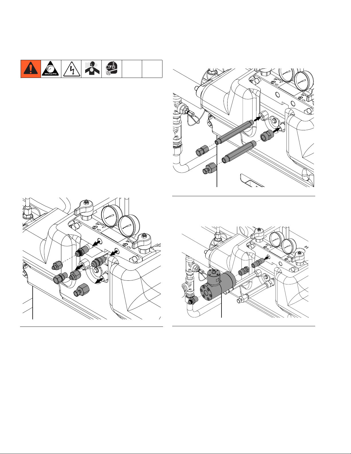
5. Remove all fittings from the outlet ports on the front
of the fluid manifold. See F
each fitting is from to make sure they are installed
on the correct side later.
IG. 4. Note which side
8. Connect flow meter and fittings to swivel fitting
already connected to fluid manifold. See F
IG. 5.
304
301
303
302
ti17016a
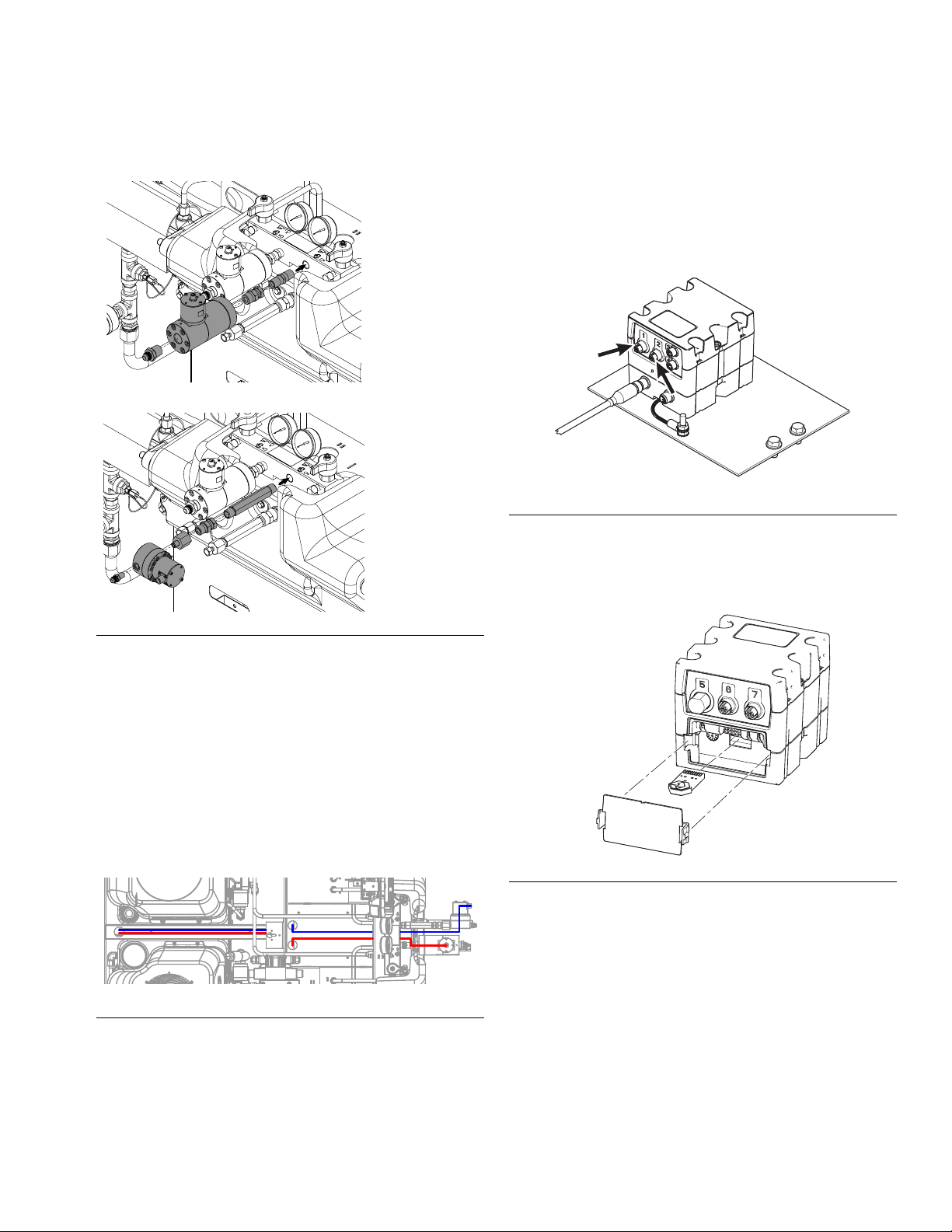
FIG. 5: Connect Fittings to Flow Meter
9. Connect the flow meter assembly to the fluid manifold as shown. See F
IG. 6.
10. Re-install the fittings that were previously removed.
See F
IG. 6.
NOTICE
Make sure to install the fittings in the correct material lines. Failure to do so will result in material
cross-contamination of the fittings and material
hoses.
ti17015a
FIG. 4: Remove Fluid Manifold Fittings
6. Connect swivel fitting (302) to fluid manifold. See
F
IG. 5.
7. Connect fittings (303 and 304) to flow meter (301).
See F
IG. 5.
11. Connect the 4-pin connector of the flow meter data
cable to the flow meter. See F
IG. 6.
ti17017a
FIG. 6: Flow Meter Installation
6 3A1657F
Page 7
12. Route the flow meter data cable as shown in FIG. 7.
ti17013a
FIG. 7: Flow Meter Data Cable Routing
13. Connect the other end to the fluid control module
installed in the electrical enclosure.
If the data cable is for the A (Red) side flow meter,
connect to port 1 on the FCM. See F
IG. 2.
If the data cable is for the B (Blue) side flow meter,
connect to port 2 on the FCM. See F
IG. 8.
Installation
ti17014a
FIG. 8: Flow Meter Data Cable Connections
3A1657F 7
Page 8
Installation
NVH Flow Meters
1. Perform HFR for NVH Pressure Relief Procedure.
See HFR for NVH operation manual for detailed
instructions.
2. Perform dispense valve Pressure Relief Proce-
dure. See dispense valve manual, page 3, for
detailed instructions.
3. Verify all air, hydraulic, and material pressures have
been relieved before continuing.
4. Perform HFR for NVH Shutdown procedure. See
HFR operation manual for detailed instructions.
5. Remove all fittings from the inlet and outlet ports on
the front of the fluid manifold. See F
IG. 9.
6. If applicable, connect the A (Red) and B (Blue)
return fittings. See F
IG. 10.
FIG. 10: Connect Return Fittings
7. Connect A (Red) flow meter and fittings to fluid
manifold. See F
IG. 11.
FIG. 9: Remove Fluid Manifold Fittings
8 3A1657F
FIG. 11: A (Red) Flow Meter Installation
Page 9
Installation
8. Connect B (Blue) flow meter and fittings to fluid
manifold. See F
IG. 12.
1:1 Ratio
24:1 or 16:1
Ratio
12. Connect the other end to the fluid control module
installed in the electrical enclosure.
If the data cable is for the A (Red) side flow meter,
connect to port 1 on the FCM. See F
IG. 14.
If the data cable is for the B (Blue) side flow meter,
connect to port 2 on the FCM. See F
IG. 14.
ti17014a
FIG. 14: Flow Meter Data Cable Connections
13. Install token into the FCM and turn the system
power on. Once the software installation is complete, remove the token.
FIG. 12: B (Blue) Flow Meter Installation
9. Connect the supply and return hoses from the applicator to the corresponding fittings.
10. Connect the 4-pin connector of the flow meter data
cable to the flow meter.
11. Route the flow meter data cable as shown in
F
IG. 13.
NOTE: For NVH - Modular systems, route the flow
meter data cable as shown in F
IG. 7, page 7.
FIG. 13: Flow Meter Data Cable Routing
ti17219a
FIG. 15: Token Installation
3A1657F 9
Page 10
Installation
HFR: Calibration Kit
In order to perform the calibration procedure the HFR
system must have circulation lines going from the system fluid manifold back to the tanks. If the system does
not have circulation lines, a calibration kit must be purchased and installed. See HFR: Flow Meter Calibra-
tion Kits for Hydraulic Dispense Valves on page 25
for the correct calibration kit number to order for your
dispense valve.
This procedure applies to the L-Head, S-Head and
GX-16 calibration kits only. See page 25 for part reference numbers.
1. Perform HFR Pressure Relief Procedure. See
HFR operation manual for detailed instructions.
2. Perform dispense valve Pressure Relief Proce-
dure. See dispense valve manual, page 3, for
detailed instructions.
7. Remove A (Red) and B (Blue) circulation fittings
from the fluid manifold. See F
IG. 16. Clean the fit-
tings then set them aside. They will not be needed.
ti17018a
FIG. 16: Remove Circulation Fittings
8. Install fittings (ref. 3) from this kit in place of the circulation fittings. See F
IG. 18.
9. De-pressurize and empty the material tank.
10. Remove material return line from tank.
3. Verify all air, hydraulic, and material pressures have
been relieved before continuing.
4. Perform HFR Shutdown procedure. See HFR oper-
ation manual for detailed instructions.
5. If material hoses from the dispense valve are connected to the HFR system, disconnect them from
the system fluid manifold to enable removing the
blue pumpline shield.
6. Remove blue plastic shield that covers the center of
the pumpline.
11. Assemble fittings and hose then connect assembled
kit to the return port of the tank as shown in F
IG. 17.
ti17019a
FIG. 17: Install Fittings and Hose
10 3A1657F
Page 11

12. Connect the other end of the hose to the fluid manifold as shown in F
IG. 18.
ti17020a
FIG. 18: Connect Hose to Fluid Manifold
13. Connect material return line to the open port of the
tee fitting at the tank. See F
IG. 17.
Installation
14. Repeat steps 9-12 for the other material side.
15. Re-install blue plastic shield that covers the center
of the pumpline.
16. Re-connect material hoses to the HFR system.
NOTE: Keep blank orifices and o-rings (items 7, 8, 9 in
this kit) for flow meter calibration.
3A1657F 11
Page 12

Calibration
Calibration
The following procedure describes how to adjust the
mass flow rate calculated by the machine. To calculate
the mass flow rate, the machine uses the chemical specific gravities entered in the Setup screens, the volumetric flow measured by the flow meters, and the K-Factor
inputs for each chemical.
The flow meters do not require regular calibration. However, if harmful materials such as solvents or abrasive
materials pass through the flow meters re-calibration will
be necessary.
NOTICE
Do not allow solvents or abrasive material to pass
through the flow meters. Failure to do so will result in
damage to the flow meters and reduced accuracy.
While this procedure adjusts the K-Factor, its purpose is
to fine-tune the calculated specific gravity of each chemical used. Because of this, it is important to have accurate chemical specific gravities entered in ADM.
To accurately measure flow from each chemical side,
some dispense valves require dispensing one chemical
at a time, while other can split the stream into two separate containers. To dispense one chemical at a time, a
blocked orifice must be installed in one side of the dispense valve to prevent fluid flow. To dispense both
chemicals simultaneously but into separate containers,
a special assembly must be installed to separate the
fluid streams.
Using a Blocked Orifice
The L-Head, S-Head, and GX-16 dispense valves
require installing a blocked orifice to calibrate fluid flow.
The blocked orifice prevents leaking fluid and cross-contamination of the fluid line not being calibrated.
NOTICE
The fluid line not being calibrated must have a
blocked orifice installed. Failure to do so will result in
fluid being pushed into the opposite fluid line during
the calibration shot. This will result in significant
labor to clear the mixed and cured material from the
fluid lines.
12 3A1657F
Page 13

Parts and Tools Required
Calibration
GX-7DI Only
• 5/16 Nut Driver
• Adjustable Wrench
•Scale
• Two large containers with lids (a hole will need to be
cut into the lid slightly larger than the spray nozzle.
Using a 5 gallon pail and removing the pull out spout
from the bung is recommended).
• Solvent and cleaning utensils to clean GX-7 mix
module and inlets.
L-Head, S-Head, GX-16
• Blocked orifice -- see dispense valve manual for part
numbers, see Related Manuals on page 3
•Scale
• Container to catch dispensed material
• L-Head Only --
• 4 mm and 6 mm hex keys
• S-Head Only --
• 5/32 hex key
• 1 in. hex wrench
• 3/8 in. hex wrench
Fusion, EP, Probler P2
•Scale
• Two containers to catch dispensed material
• Adjustable wrench
• Fusion Gun and EP Gun Only --
• Ratio checking assembly 24F227
• Probler P2 Only --
• Calibration kit 24J326
MD2 Valve
• Ratio Check Adapter:
Part No. 255247 for 1:1 MD2 Valves
Part No. 255245 for 10:1 MD2 Valves
• Adjustable Wrench
•Scale
• Two small containers, must have a small enough rim
to separately catch each material dispensed from
the ratio check adapter
• GX-16 Only --
• 7/16 in. hex wrench
• Blocked orifice -- see dispense valve manual for
part numbers, see Related Manuals on page 3
3A1657F 13
Page 14

Calibration
Calibrate Material Weight Measurement
For more detailed instructions regarding steps in this
procedure, see Related Manuals listed on page 3.
1. If not already completed, install the flow meters. See
Installation starting on page 12.
2. If the HFR system does not have circulation lines
going from the system fluid manifold to the tanks,
order and install the appropriate calibration kit. See
HFR: Calibration Kit on page 10.
3. Perform HFR Pressure Relief Procedure. See
HFR operation manual listed on page 3 for detailed
instructions.
4. Perform dispense valve Pressure Relief Proce-
dure. See dispense valve manual listed on page 3
for detailed instructions.
5. Verify all air, hydraulic, and material pressures have
been relieved before continuing.
6. Perform HFR Shutdown procedure. See HFR oper-
ation manual for detailed instructions.
7. Place a bucket under the dispense valve to catch
spilled material.
For S-Head and L-Head Dispense Valves Only --
a. Remove the four hex bolts on the chemical side
not being calibrated.
b. Remove the existing orifice and nozzle assem-
bly and replace with the blocked orifice and nozzle assembly.
c. With the blocked orifice and nozzle assembly
installed, install the four hex bolts previously
removed and tighten.
For GX-16 Dispense Valve Only --
a. Use the 7/16 in. hex wrench to remove the ori-
fice on the chemical stream not being calibrated.
b. Lubricate o-rings then install the blank restrictor
orifice.
For Fusion and EP Gun Only --
a. Remove the gun fluid manifold from the gun.
See gun manual listed on page 3.
b. Connect gun fluid manifold to ratio check
assembly 24F227.
8. Prepare dispense valve for calibration dispense:
For GX7-DI Dispense Valves --
a. Disable air assist to the spray head air cap.
b. Close off material flow to the dispense head for
the chemical NOT being calibrated. Turn the
valve on the coupling block manifold fully clockwise until tight.
c. Open material flow to the dispense head for the
ti17021a
chemical being calibrated. Turn the valve on the
coupling block manifold fully counter-clockwise
until tight.
d. Remove the Air Cap Nut, Pressure Cap Disc
(PCD) retainer nut, and the PCD.
14 3A1657F
Page 15

Calibration
For Probler P2 Gun Only --
a. Disconnect both material lines at the gun. See
gun manual listed on page 3.
b. Attach material lines to fluid manifold (1)
included in calibration kit 24J326. See F
c. Place o-rings (2) in correct location then attach
fluid manifold to the base (3) of the calibration
kit.
ti17022a
FIG. 19: Kit 24J326
IG. 19.
For L-Head, S-Head, GX-7 DI, and GX-16 Dispense
Valves Only --
• If calibrating the A (Red) side, close the B (Blue)
valve on the fluid manifold. Make sure the A
(Red) valve is open.
• If calibrating the B (Blue) side, close the A (Red)
valve on the fluid manifold. Make sure the B
(Blue) valve is open.
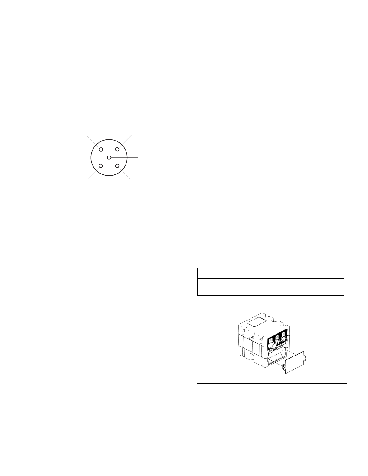
NOTE: The valves on the fluid manifold are closed when
pointing to the side, as shown in F
IG. 20. They are open
when pointing forwards.
A
B
For MD2 Valve Only --
a. Use an adjustable wrench to remove the static
mixer.
b. Install the ratio check adapter onto the dispense
valve.
ti17021a
FIG. 20: Fluid Manifold Valves - shown closed
All Assemblies --
9. Turn the main power switch on the HFR to the ON
position.
10. Press the ADM Power On/Off button (CA) to enable
the system.
CA
ti17021a
FIG. 21: Fluid Manifold Valves
3A1657F 15
Page 16

Calibration
11. Press to dispense a shot to prime the material
lines.
12. Remove container from below the dispense valve.
13. Press repeatedly to select Standby mode.
14. Press to access the Setup screens.
15. Use the arrow keys to navigate to System
screen #3.
21. Press to exit the System screen then use the
arrow keys to navigate to the Calibration screen.
22. Press to access the weight calibration and
material specific gravity screen.
23. Enter the material specific gravity in the A (Red) and
B (Blue) specific gravity input boxes.
16. Press then use the arrow keys to navigate to
the A (Red) and B (Blue) flow meter dropdown
menus.
17. Enter material specific gravity in the A (Red) and B
(Blue) Specific gravity input boxes. This information
may be entered on the System 3 screen, or the Calibration screen depending on the specific machine
model. See step 23.
18. Use the dropdown menus to select the type of flow
meters installed.
19. Enter 0 in the Alarm % fields. This will prevent
alarms during the calibration dispense that could
prevent dispensing.
20. Select either “RED:1” or “BLUE:1” for the ratio display.
24. Press to go to the main Calibration screen.
16 3A1657F
Page 17

Calibration
25. Press to go to the flow meter calibration
screen.
26. Enter a value in the Cal. Setpoint input box that is
close to what is used during normal dispensing. Ver-
ify the softkey option is active.
27. Prepare containers for calibration dispense:
All Assemblies --
28. Press to begin dispensing then press again to
stop.
NOTE: For better results, it is recommended to dispense
for a minimum of 10 seconds.
29. Weigh the container(s) and record the weight(s).
Subtract the weight of each bucket measured before
the shot to obtain the weight of each material dispensed.
30. Use the arrow keys to navigate to the applicable
A (Red) or B (Blue) weight box below the
icon and enter the weight of the dispensed material(s).
31. Record the K-factor(s) shown on the screen after
the material weight(s) are entered.
32. Repeat steps 27 to 31 at least four times to dispense many calibration shots. Record the weights
and K-factors shown on the screen for each shot.
For L-Head, S-Head, and GX-16 Dispense Valves
Only --
a. Weigh a container and record the weight.
b. Place container below dispense valve.
For Fusion, EP, Probler P2, and MD2 Dispense
Valves Only --
a. Mark two containers as A and B.
b. Weigh each container and record the weights.
c. Place containers below the dispense valve to
catch the each fluid separately.
NOTE: The K-factor should be within 0.5% of the average value for all runs.
33. If any K-factors are not within 0.5% of the average
K-factor value for all shots then:
a. Check all electrical connections.
b. Check material connections.
c. Check to make sure there is no air in the mate-
rial lines.
34. Perform HFR Pressure Relief Procedure. See
HFR operation manual for detailed instructions.
35. Perform dispense valve Pressure Relief Proce-
dure. See dispense valve manual, page 3, for
detailed instructions.
36. Verify all air, hydraulic, and material pressures have
been relieved before continuing.
37. Perform HFR Shutdown procedure. See HFR operation manual for detailed instructions.
3A1657F 17
Page 18

Calibration
38. Prepare dispense valve:
For GX7-DI Dispense Valves --
a. Close off material flow to the dispense head for
BOTH chemicals. Turn the valve on the coupling
block manifold fully clockwise until tight.
b. Remove and clean the mixing module retainer.
c. Remove and clean the mix module. The dis-
pense valve can be manually cycled open and
closed by pressing the dispense valve button on
the Maintenance screen. Cycle open and
closed once to pull the module partially off of
the valve rod.
d. Remove the inlet screen and check valve
assembly for the chemical side that was NOT
being calibrated and inspect for cross contamination of chemical.
e. Remove manifold and completely clean if cross-
over is found. Clean parts with solvent or
replace as necessary.
For Probler P2 Gun Only --
a. Remove material lines from calibration kit.
b. Remove calibration kit and clean for future use.
c. Attach material lines to gun.
For MD2 Valve Only --
a. Remove ratio check nozzle and clean for future
use.
b. Install static mixer.
All Assemblies --
39. Navigate to the System 3 screen then update the
Alarm % value to the desired percent.
f. Return to step 8 and repeat calibration steps for
the other chemical side.
For L-Head, S-Head, and GX-16 Dispense Valves
Only --
a. Remove blocked orifice and replace with origi-
nal orifice.
b. Clean the used blocked orifice for future use.
c. Go to step 27 to repeat procedure to calibrate
the other material line.
For Fusion and EP Guns Only --
a. Remove the ratio check assembly and clean for
future use.
b. Attach fluid manifold to gun.
18 3A1657F
Page 19
Flow Meter Connector Pinout
Flow Meter Connector Pinout
The system utilizes a 5-pin CAN connection for communication with the flow meter. If a non-Graco flow meter is
used the flow meter signal must be converted to the following 5-pin connection.
NOTE: The connection shown is the FCM connector,
not the CAN cable pins.
1
4
FIG. 22: FCM 5-pin Connector Input
2
5
3
Maintenance
Install Upgrade Token
NOTE: The Motor Control Module, Fluid Control Mod-
ule, and Temperature Control Module connection to the
system is temporarily disabled during the installation of
upgrade tokens.
To install software upgrades:
1 +10-30 VDC Supply
2 Signal out
3Ground
4 Not Used
5 Not Used
The software version history for each system can be
viewed in the technical support section at
www.graco.com.
Token Application
16G407 Ratio Monitoring (Flow Meters):
- Fluid Control Module
1. Use correct software token stated in the table. See
Graco Control Architecture
manual for instructions.
NOTE: Upgrade all modules in the system to the
software version on the token, even if you are
replacing only one or two modules. Different software versions may not be compatible.
All data in the module (System Settings, USB Logs,
Recipes, Maintenance Counters) may be reset to
factory default settings. Download all settings and
user preferences to a USB before the upgrade, for
ease of restoring them following the upgrade.
See manuals for locations of specific GCA components.
3A1657F 19
™
Module Programming
ti12334a1
FIG. 23
Page 20
Parts
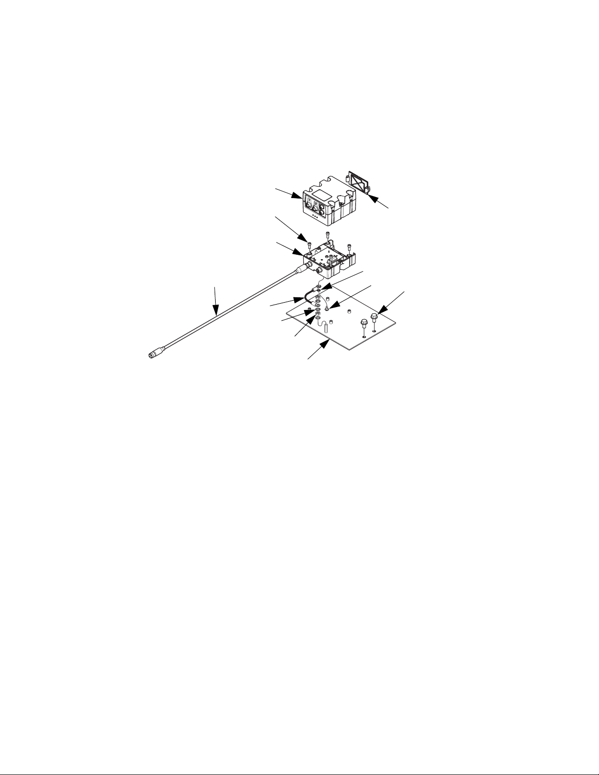
Parts
HFR and NVH: Flow Meter Electronics Kit, 24J318
103
107
102
111
104
109
Ref Part Description Qty
101 24J328 PLATE, mounting, electronics 1
102 289697 MODULE, base 1
103 289696 MODULE, FCM 1
104 24H240 HARNESS, wire, ground, term, 9 in. 1
105 102063 WASHER, lock, ext 1
106 114993 SCREW, machine, pan wash head 1
107 102598 SCREW, cap, socket head 4
108 277674 ENCLOSURE, cube door 1
109 100985 WASHER, lock ext 3
110 100015 NUT, hex mscr 2
111 121002 CABLE, CAN, female / female,
1.5 m
112 111800 SCREW, cap, hex head 2
113 123680 CABLE, CAN, male/male,
0.5 m (not shown)
110
1
1
101
105
106
108
112
ti17023a
20 3A1657F
Page 21

HFR: 3000 Series Flow Meter Kits
201
Parts
203
202
206
205
204
Quantity
24J319,
Ref Part Description
201 258718 METER, gear, S3000 1
239716 METER, gear, G3000 1
244292 METER, gear, G3000HR 1
202 262205 FITTING, swivel, npt x JIC 1 1 1
203 262206 FITTING, swivel, 1/4 npt x 6 JIC 1 1 1
204 123596 ADAPTER, 5/16 JIC x 1/4 npt 1 1 1
205 123597 ADAPTER, 3/8 JIC x 1/4 npt 1 1 1
206 125103 HARNESS, M12 x cir, 5-pin x 3-pin, male
x female
S3000
1 1 1
24J320,
G3000
24J321,
G3000HR
ti17024a
3A1657F 21
Page 22

Parts
HFR: 6000 Series Flow Meter Kits
301
303
302
304
305
Quantity
24J322,
Ref Part Description
301 246190 METER, helical gear, HG6000 1
246652 METER, helical gear, HG6000HR 1
302 114190 SWIVEL, stainless steel, 1/2 npt 1 1
303 114496 FITTING, nipple 1 1
304 502033 FITTING, bushing, pipe 1 1
305 123657 CABLE, 5-pin, male / female, 3.5 m 1 1
HG6000
24J323,
HG6000HR
ti17016a
22 3A1657F
Page 23

NVH: 24:1 and 16:1 Flow Meter Kits
614
601
615
Parts
605
606
613
607
609
608
Ref Part Description
601 246652 METER, heli gear, high resolution 1 1
602 289814 METER, gear, assembly, G3000HR 1 1
603 123657 CABLE, 5pin, male/female, 3.5 meter 1 1
604 125103 HARNESS, M12xcir, 5pinx3pin, male x female 1 1
605 156877 FITTING, nipple, long 1 1
606 123980 FITTING, swivel, 3/4x1/2, male x female, sst, 3.5 1 1
607 124286 FITTING, adapter, 3/4NPTM x 8 JICM 1 1
608 123597 ADAPTER, 3/8 JIC x 1/4 NPT 1 1
609 124814 FITTING, reducer, 1/2NPTx1/4NPT, female x male, ss 1 1
610 114190 SWIVEL, sst, 1/2 NPT 1 1
611 124586 COUPLING, hex, 1/2NPT, ss, 3k, 316 1
612 124152 FITTING, elbow, JIC06 x 1/2 NPT, ss 1
613 16W140 FITTING, nipple, 1/2NPTx6.0 long, ss 2
614 16W141 FITTING, nipple, 3/8NPTx7.0 long, ss 1
615 112569 FITTING, union, swivel 1
616 257700 RESTRICTOR, orifice assembly, blank 2 2
617 16G407 TOKEN, GCA, upgrade, ratio monitor 1 1
602
610
612
24T182,
24:1 or 16:1 Flow
Meter Kit - Cart
613
Quantity
24T200,
24:1 or 16:1 Flow
Meter Kit - Modular
611
3A1657F 23
Page 24

Parts
NVH: 1:1 Flow Meter Kits
705
711
701
710
703
704
703
704
707
709
706
708
Quantity
24T183,
1:1 Flow Meter
Ref Part Description
701 246652 METER, heli gear, high resolution 2 2
702 123657 CABLE, 5pin, male/female, 3.5meter 2 2
703 156877 FITTING, nipple, long 2 2
704 123980 FITTING, swivel, 3/4x1/2, male x female, sst, 3.5 2 2
705 124286 FITTING, adapter, 3/4NPTM x 8 JICM 1 1
706 15Y934 FITTING, 5/8 JIC/3/4 NPT 1 1
707 124586 COUPLING, hex, 1/2NPT, ss, 3k, 316 1
708 126979 FITTING, adapter, 1/2NPTF x 10JICF, ss 1
709 16W140 FITTING, nipple, 1/2NPTx6.0 long, ss 1
710 16W141 FITTING, nipple, 3/8NPTx7.0 long, ss 1
711 112569 FITTING, union, swivel 1
712 257700 RESTRICTOR, orifice assembly, blank 2 2
713 16G407 TOKEN, GCA, upgrade, ratio monitor 1 1
24 3A1657F
Kit - Cart
24T201,
1:1 Flow Meter
Kit - Modular
Page 25

HFR: Flow Meter Calibration Kits for Hydraulic Dispense Valves
403
401
402
404
406
Parts
405
Quantity
24J324,
Ref Part Description
401 262184 HOSE, b, 10 ft., 3/8 in., moisture-lok, mild
steel
402 117506 FITTING, swivel, 1/4 npt x #6 JIC 2 2 2
403 122311 FITTING, 9/16-18 JIC x 1/4 npt 2 2 2
404 124281 FITTING, coupling, 1/2 npt x 1/4 npt,
female / female, mild steel
405 103475 FITTING, tee, pipe 2 2 2
406 158491 FITTING, nipple 4 4 2
407* M0934A-4 KIT, L-Head injection nozzle, blank 2
24A036 KIT, S-Head injection nozzle, with needle,
blank
257700 RESTRICTOR, orifice, blank 2
408* 285967 O-RING, #006 epr 2
409* 122679 O-RING, epr, #902 2
* Parts 407, 408, 409 not shown.
L-Head Kit
2 2 2
2 2 2
24J325,
S-Head Kit
2
24J357,
GX-16 Kit
ti17025a
3A1657F 25
Page 26

Parts
Flow Meter Calibration Kit for Probler P2 Gun, 24J326
501
502
503
ti17021a
Ratio Check Kit for Fusion Gun, 24F227
Fluid manifold shown
for reference only
ti17026a
Ref Part Description Qty
501 246012 MANIFOLD, fluid 1
502 117520 O-RING 2
503 24F227 KIT, ratio check 1
See instruction manual 3A0861 for parts information.
Ratio Check Adapters for MD2 Valve
ti12392a1
255247 shown
Use ratio check adapter 255247 for 1:1 MD2 valves.
Use 255245 for 10:1 MD2 valves.
26 3A1657F
Page 27

Technical Data
See Technical Data in the HFR or HFR for NVH system manuals for more information.
Wetted Parts . . . . . . . . . . . . . . . . . . . . . . . . . . . . . . . . . 303 stainless steel, tungsten carbide, PTFE
Technical Data
3A1657F 27
Page 28

Graco Standard Warranty
Graco warrants all equipment referenced in this document which is manufactured by Graco and bearing its name to be free from defects in
material and workmanship on the date of sale to the original purchaser for use. With the exception of any special, extended, or limited warranty
published by Graco, Graco will, for a period of twelve months from the date of sale, repair or replace any part of the equipment determined by
Graco to be defective. This warranty applies only when the equipment is installed, operated and maintained in accordance with Graco’s written
recommendations.
This warranty does not cover, and Graco shall not be liable for general wear and tear, or any malfunction, damage or wear caused by faulty
installation, misapplication, abrasion, corrosion, inadequate or improper maintenance, negligence, accident, tampering, or substitution of
non-Graco component parts. Nor shall Graco be liable for malfunction, damage or wear caused by the incompatibility of Graco equipment with
structures, accessories, equipment or materials not supplied by Graco, or the improper design, manufacture, installation, operation or
maintenance of structures, accessories, equipment or materials not supplied by Graco.
This warranty is conditioned upon the prepaid return of the equipment claimed to be defective to an authorized Graco distributor for verification of
the claimed defect. If the claimed defect is verified, Graco will repair or replace free of charge any defective par ts. The equipment will be returned
to the original purchaser transportation prepaid. If inspection of the equipment does not disclose any defect in material or workmanship, repairs will
be made at a reasonable charge, which charges may include the costs of parts, labor, and transportation.
THIS WARRANTY IS EXCLUSIVE, AND IS IN LIEU OF ANY OTHER WARRANTIES, EXPRESS OR IMPLIED, INCLUDING BUT NOT LIMITED
TO WARRANTY OF MERCHANTABILITY OR WARRANTY OF FITNESS FOR A PARTICULAR PURPOSE.
Graco’s sole obligation and buyer’s sole remedy for any breach of warranty shall be as set forth above. The buyer agrees that no other remedy
(including, but not limited to, incidental or consequential damages for lost profits, lost sales, injury to person or property, or any other incidental or
consequential loss) shall be available. Any action for breach of warranty must be brought within two (2) years of the date of sale.
GRACO MAKES NO WARRANTY, AND DISCLAIMS ALL IMPLIED WARRANTIES OF MERCHANTABILITY AND FITNESS FOR A
PARTICULAR PURPOSE, IN CONNECTION WITH ACCESSORIES, EQUIPMENT, MATERIALS OR COMPONENTS SOLD BUT NOT
MANUFACTURED BY GRACO. These items sold, but not manufactured by Graco (such as electric motors, switches, hose, etc.), are subject to
the warranty, if any, of their manufacturer. Graco will provide purchaser with reasonable assistance in making any claim for breach of these
warranties.
In no event will Graco be liable for indirect, incidental, special or consequential damages resulting from Graco supplying equipment hereunder, or
the furnishing, performance, or use of any products or other goods sold hereto, whether due to a breach of contract, breach of warranty, the
negligence of Graco, or otherwise.
FOR GRACO CANADA CUSTOMERS
The Parties acknowledge that they have required that the present document, as well as all documents, notices and legal proceedings entered into,
given or instituted pursuant hereto or relating directly or indirectly hereto, be drawn up in English. Les parties reconnaissent avoir convenu que la
rédaction du présente document sera en Anglais, ainsi que tous documents, avis et procédures judiciaires exécutés, donnés ou intentés, à la suite
de ou en rapport, directement ou indirectement, avec les procédures concernées.
Graco Information
For the latest information about Graco products, visit www.graco.com.
TO PLACE AN ORDER, contact your Graco distributor or call to identify the nearest distributor.
Phone: 612-623-6921 or Toll Free: 1-800-328-0211 Fax: 612-378-3505
All written and visual data contained in this document reflects the latest product information available at the time of publication.
GRACO INC. AND SUBSIDIARIES • P.O. BOX 1441 • MINNEAPOLIS MN 55440-1441 • USA
Copyright 2011, Graco Inc. All Graco manufacturing locations are registered to ISO 9001.
Graco reserves the right to make changes at any time without notice.
For patent information, see www.graco.com/patents.
Original instructions. This manual contains English. MM 3A1657
Graco Headquarters: Minneapolis
International Offices: Belgium, China, Japan, Korea
www.graco.com
Revised April 2014
 Loading...