

Page 1
Instructions/Parts
16G351 Electric Power
3A1324B
Conversion Kit
Converts ProMix 2KE Electronic Proportioners from an intrinsically safe air-powered
alternator power supply to a non-intrinsically safe electric power supply.
For professional use only.
Not approved for use in European explosive atmosphere locations.
Important Safety Instructions
Read all warnings and instructions in this
manual and your separate ProMix 2KE
manuals. Save these instructions.
Converting the ProMix 2KE proportioner from an
air-powered alternator power supply to an electric
power supply voids the intrinsically safe rating of the
equipment.
EN
Kit Parts
Ref. Part Description Qty.
401 15V747 POWER SUPPLY, 24 VDC, 2.5 A,
60 watt, B-code
402 116320 SWITCH, rocker, power 1
403 115306 FILTER, power line 1
404 114095 BLOCK, terminal 1
405 112144 SCREW, machine, pan head 4
406 109467 SCREW, machine, pan head 2
407 103833 SCREW, machine 2
408 100139 PLUG, pipe 1
410 16H077 HARNESS, 2-wire; 8 in. (203 mm) 1
411 16H078 HARNESS, 3-wire; 4 in. (102 mm) 1
413 15V206 CABLE, CAN; 10 ft (3 m) 1
1
Page 2
Warnings
Warnings
The following warnings are for the setup, use, grounding, maintenance, and repair of this equipment. The exclamation point symbol alerts you to a general warning and the hazard symbols refer to procedure-specific risks. When
these symbols appear in the body of this manual, refer back to these Warnings. Product-specific hazard symbols and
warnings not covered in this section may appear throughout the body of this manual where applicable.
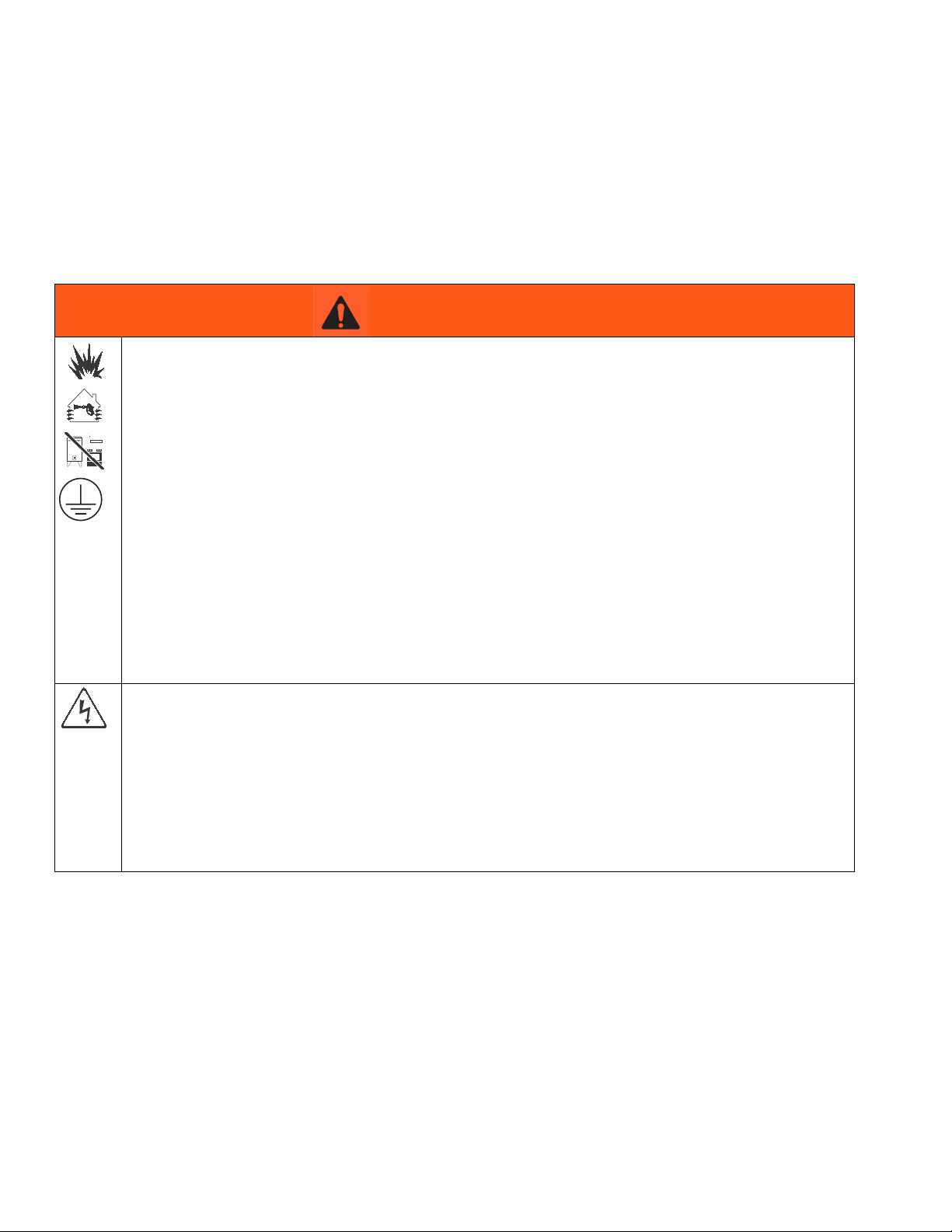
WARNING
FIRE AND EXPLOSION HAZARD
Flammable fumes, such as solvent and paint fumes, in work area can ignite or explode. To help prevent
fire and explosion:
• Use equipment only in well ventilated area.
• Eliminate all ignition sources; such as pilot lights, cigarettes, portable electric lamps, and plastic drop
cloths (potential static arc).
• Keep work area free of debris, including solvent, rags and gasoline.
• Do not plug or unplug power cords, or turn power or light switches on or off when flammable fumes are
present.
• Ground all equipment in the work area. See Grounding instructions.
• Use only grounded hoses.
• Hold gun firmly to side of grounded pail when triggering into pail.
• If there is static sparking or you feel a shock, stop operation immediately. Do not use equipment until
you identify and correct the problem.
• Keep a working fire extinguisher in the work area.
ELECTRIC SHOCK HAZARD
This equipment must be grounded. Improper grounding, setup, or usage of the system can cause electric
shock.
• Turn off and disconnect power at main switch before disconnecting any cables and before servicing
equipment.
• Connect only to grounded power source.
• All electrical wiring must be done by a qualified electrician and comply with all local codes and
regulations.
2 3A1324B
Page 3
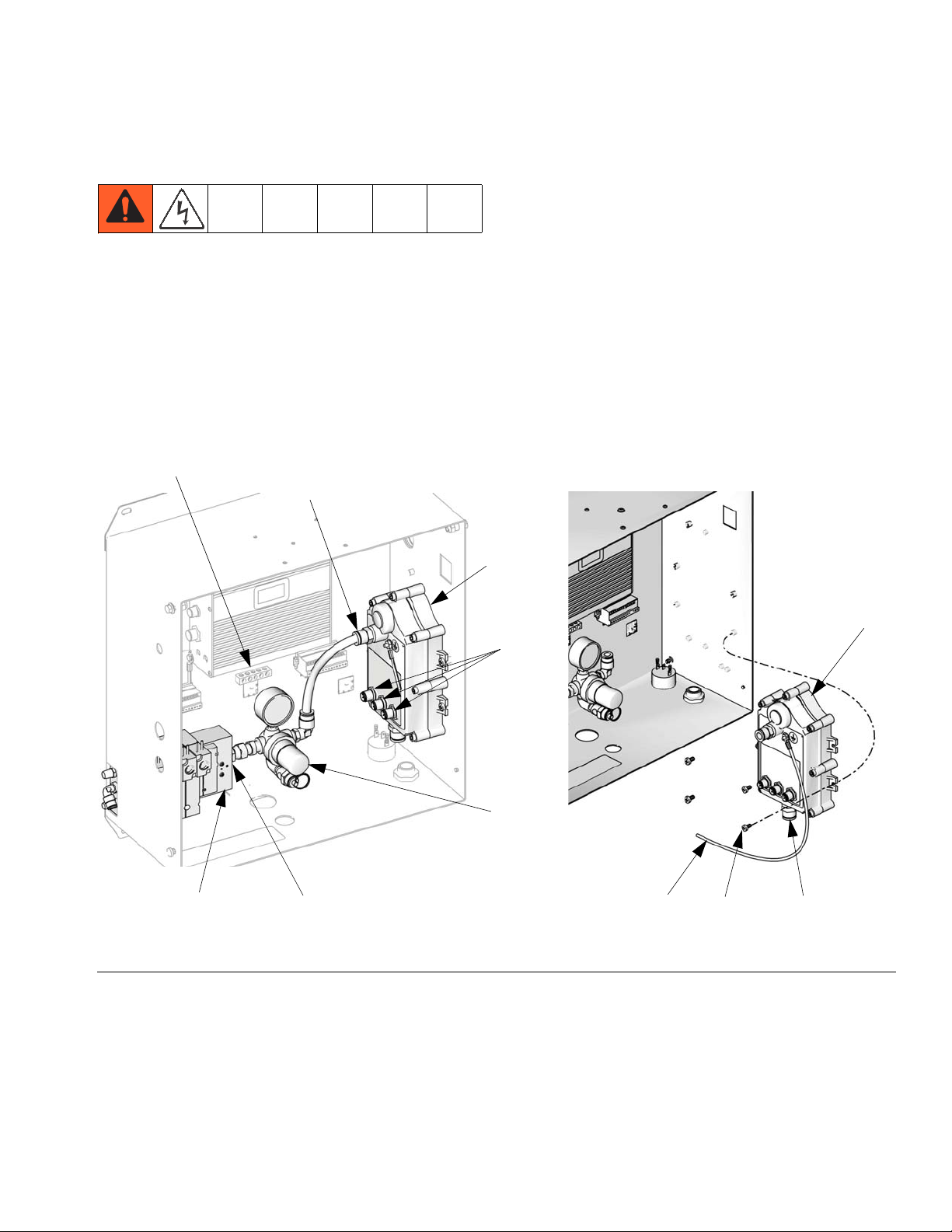
Remove the Alternator
Remove the Alternator
4. Systems with a USB Module: Disconnect and
save the cable (412) that runs from the AFCM to the
alternator.
1. Shut off the system’s main air valve. Open the control box.
2. See F
3. Disconnect the power supply cables from the
IG. 1. Disconnect output power cable connec-
tions from alternator module (A). Disconnect ground
lead (G) from control box ground terminal (T).
Advanced Fluid Control Module (AFCM),
USB Module, and Display Module.
T
Air regulator
line
5. Disconnect air regulator line and exhaust air line
from alternator module. Remove air regulator
assembly (R) from solenoid manifold (M). Install
plug (408) from kit in the open manifold port.
6. Remove four screws (S) from mounting to remove
alternator from control box.
A
Cable
connectors
A
R
ti16456a
M
FIG. 1. Remove Alternator Module
3A1324B 3
Install plug (408)
in open port
GS
ti16455a
Air exhaust
line
Page 4

Install the Kit
Install the Kit
Component Installation
1. Shut off electrical power at the main panel.
2. See F
IG. 2. Remove the square knockout in the side
of the control box. Install the power switch (402).
3. Install the power supply (401), line filter (403), and
terminal block (404), using supplied screws (405,
407, 406), as shown.
4. See F
IG. 2. Connect wire harness (410/LF) to the
line filter (403) and switch (402), as shown. See also
F
IG. 6, Electrical Schematic.
2: PS(L)
2A: LF(L)
FCM
5. Connect the power supply wire harness (PS) to the
switch (402), as shown. See also F
IG. 6, Electrical
Schematic. Connect the PS ground wire to the
ground terminal (T) of the control box.
6. See F
IG. 5. Connect wire harness (411) to the line
filter (403) and terminal block (404), as shown. See
also F
IG. 6, Electrical Schematic.
402
1: PS(N)
1A: LF(N)
T
PS(GND)
FIG. 2. Install Power Supply Kit
405
401
PS(L)
407
406
PS(N)
LF(L)
LF(N)
C
410
403
411 (see F
404
IG. 5)
ti16454b
4 3A1324B
Page 5

Install the Power CAN Cables
Install the Kit
Systems with a USB Module
1. See FIG. 3. Connect cable (413) to J6 of the display
module and to connector P3 of the USB module.
2. Connect saved cable (412) to connector P4 of the
USB module and to J8 of the Advanced Fluid Control Module.
3. Connect the power supply CAN cable (C, F
J7 on the Advanced Fluid Control Module (F
4. See your ProMix 2KE Operation manual for instructions on using the USB module.
USB Module (if present)
P4
Connect cable
(412) here
P3
Connect cable
(413) here
TI16580a
IG. 2) to
IG. 3).
Systems without a USB Module
1. See FIG. 4. Connect cable (413) to J6 of the display
module and to J8 of the Advanced Fluid Control
Module.
2. Connect the power supply CAN cable (C, F
J7 on the Advanced Fluid Control Module (F
Display Module
IG. 2) to
IG. 4).
TI16604a
J6
Connect cable (413) here
Advanced Fluid Control Module
J8
Connect
cable
(412) here
Display Module
TI16604a
J6
Connect cable (413) here
Advanced Fluid Control Module
J7
Connect
cable (C)
here
J8
Connect
cable
(413) here
TI16579a
FIG. 4. Install Power CAN Cables (without USB
Module)
TI16602a
J7
Connect
cable (C)
here
TI16579a
FIG. 3. Install Power CAN Cables (with USB Module)
3A1324B 5
TI16602a
Page 6

Install the Kit
Power Connection
All electrical wiring must be completed by a qualified
electrician and comply with all local codes and
regulations.
Enclose all cables routed in the spray booth and high
traffic areas in conduit to prevent damage from paint,
solvent, and traffic.
The ProMix 2KE operates with 85-250 VAC, 50/60 Hz
input power, with a maximum of 2 amp current draw.
The power supply circuit must be protected with a 15
amp maximum circuit breaker.
Not included with kit:
• Power supply cord compatible to your local power
configuration. Wire gauge size must be 8-14 AWG.
• The input power access port is 22.4 mm (0.88 in.) in
diameter. It accepts a bulkhead strain relief fitting or
conduit.
1. Verify that electrical power at the main panel is shut
off.
2. Connect electrical cord to the terminal block (404)
as shown in F
IG. 5.
3. Close the Control Box. Restore power.
4. Follow instructions in Grounding in your ProMix
2KE Operation Manual.
5. See your ProMix 2KE Operation manual for operating instructions.
Line
Neutral
FIG. 5. Terminal Block Electrical Connections
TERMINAL
BLOCK
L N GRND
WIRE
HARNESS
(411)
L N GRND
LINE POWER
FILTER
L N
WIRE
HARNESS
(410)
2A
SWITCH
ROCKER
2
Ground
1A
1
POWER
SUPPLY
411
404
ti16391a
POWER SUPPLY
WIRE HARNESS
GRND
FIG. 6. Electrical Schematic
6 3A1324B
Page 7

Install the Kit
3A1324B 7
Page 8

Graco Standard Warranty
Graco warrants all equipment referenced in this document which is manufactured by Graco and bearing its name to be free from defects in
material and workmanship on the date of sale to the original purchaser for use. With the exception of any special, extended, or limited warranty
published by Graco, Graco will, for a period of twelve months from the date of sale, repair or replace any part of the equipment determined by
Graco to be defective. This warranty applies only when the equipment is installed, operated and maintained in accordance with Graco’s written
recommendations.
This warranty does not cover, and Graco shall not be liable for general wear and tear, or any malfunction, damage or wear caused by faulty
installation, misapplication, abrasion, corrosion, inadequate or improper maintenance, negligence, accident, tampering, or substitution of
non-Graco component parts. Nor shall Graco be liable for malfunction, damage or wear caused by the incompatibility of Graco equipment with
structures, accessories, equipment or materials not supplied by Graco, or the improper design, manufacture, installation, operation or
maintenance of structures, accessories, equipment or materials not supplied by Graco.
This warranty is conditioned upon the prepaid return of the equipment claimed to be defective to an authorized Graco distributor for verification of
the claimed defect. If the claimed defect is verified, Graco will repair or replace free of charge any defective parts. The equipment will be returned
to the original purchaser transportation prepaid. If inspection of the equipment does not disclose any defect in material or workmanship, repairs will
be made at a reasonable charge, which charges may include the costs of parts, labor, and transportation.
THIS WARRANTY IS EXCLUSIVE, AND IS IN LIEU OF ANY OTHER WARRANTIES, EXPRESS OR IMPLIED, INCLUDING BUT NOT LIMITED
TO WARRANTY OF MERCHANTABILITY OR WARRANTY OF FITNESS FOR A PARTICULAR PURPOSE.
Graco’s sole obligation and buyer’s sole remedy for any breach of warranty shall be as set forth above. The buyer agrees that no other remedy
(including, but not limited to, incidental or consequential damages for lost profits, lost sales, injury to person or property, or any other incidental or
consequential loss) shall be available. Any action for breach of warranty must be brought within two (2) years of the date of sale.
GRACO MAKES NO WARRANTY, AND DISCLAIMS ALL IMPLIED WARRANTIES OF MERCHANTABILITY AND FITNESS FOR A
PARTICULAR PURPOSE, IN CONNECTION WITH ACCESSORIES, EQUIPMENT, MATERIALS OR COMPONENTS SOLD BUT NOT
MANUFACTURED BY GRACO. These items sold, but not manufactured by Graco (such as electric motors, switches, hose, etc.), are subject to
the warranty, if any, of their manufacturer. Graco will provide purchaser with reasonable assistance in making any claim for breach of these
warranties.
In no event will Graco be liable for indirect, incidental, special or consequential damages resulting from Graco supplying equipment hereunder, or
the furnishing, performance, or use of any products or other goods sold hereto, whether due to a breach of contract, breach of warranty, the
negligence of Graco, or otherwise.
FOR GRACO CANADA CUSTOMERS
The Parties acknowledge that they have required that the present document, as well as all documents, notices and legal proceedings entered into,
given or instituted pursuant hereto or relating directly or indirectly hereto, be drawn up in English. Les parties reconnaissent avoir convenu que la
rédaction du présente document sera en Anglais, ainsi que tous documents, avis et procédures judiciaires exécutés, donnés ou intentés, à la suite
de ou en rapport, directement ou indirectement, avec les procédures concernées.
Graco Information
For the latest information about Graco products, visit www.graco.com.
TO PLACE AN ORDER, contact your Graco distributor or call to identify the nearest distributor.
Phone: 612-623-6921 or Toll Free: 1-800-328-0211 Fax: 612-378-3505
All written and visual data contained in this document reflects the latest product information available at the time of publication.
GRACO INC. AND SUBSIDIARIES • P.O. BOX 1441 • MINNEAPOLIS MN 55440-1441 • USA
Copyright 2010, Graco Inc. All Graco manufacturing locations are registered to ISO 9001.
Graco reserves the right to make changes at any time without notice.
Original instructions. This manual contains English. MM 3A1324
Graco Headquarters: Minneapolis
International Offices: Belgium, China, Japan, Korea
www.graco.com
Revised 08/2011
 Loading...