

Page 1
ti23074a
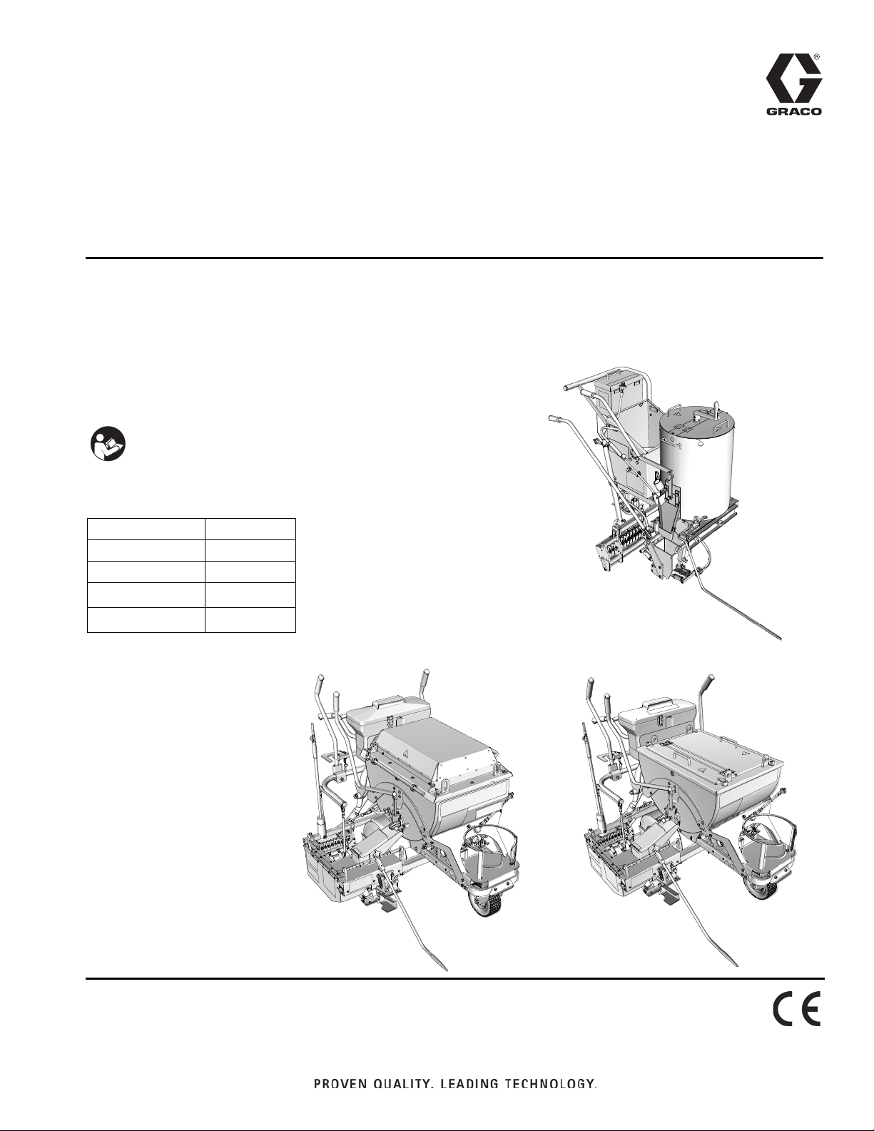
ThermoLazer 300TC
ThermoLazer ProMelt
ti23073a
ThermoLazer 200/200TC
ti22634a
Operation
ThermoLazer® 200/200TC/300TC and
™
ThermoLazer ProMelt
Pavement Marking
Systems
- For professional application of thermoplastic traffic marking compound materials
(reflective beads applied simultaneously with screeding) -
- For outdoor use only (not to be operated in rain or damp conditions) -
Fuel: LP Gas (Propane Vapor)
Burner capacities: See Technical Data, page 38.
Material capacity (max): 200-300 lb (91-136 kg)
IMPORTANT SAFETY INSTRUCTIONS
Read all warnings and instructions in this
manual. Save these instructions.
Related Manuals:
2
Repair 3A1320
Parts 3A1321
Double Bead Box 3A0004
SmartDie
FlexDie
™
II
™
3A1738
3A1738
3A1319F
EN
Page 2

System Chart
System Chart
SmartDie II used on ThermoLazer 300TC and ProMelt only.
Smart Die II
Part No. Smart Die Description
17A173 2 in. (5 cm)
24H431 3 in. (8 cm)
24H426 4 in. (10 cm)
24H432 5 in. (12 cm)
24H427 6 in. (15 cm)
24H433 7 in. (18 cm)
24H428 8 in. (20 cm)
24H434 9 in. (22.5 cm)
24H429 10 in. (25 cm)
24H430 12 in. (30 cm)
‡17A174 16 in. (41 cm)
24H437 3-3-3 in. (8-8-8 cm)
24H435 4-3-4 in. (10-8-10 cm)
24H436 4-4-4 in. (10-10-10 cm)
24J785 4-6-4 in. (10-15-10 cm)
‡17A175 6-4-6 in. (15-10-15 cm)
‡ Requires 16” (40 cm) Conversion Bead System Kit for 300TC/ProMelt Only.
- 17B190 Kit, accy, 16” (40 cm) Single Drop Bead System
- 17B189 Kit, accy, 16” (40 cm) Double Drop Bead Box (requires 17B190 to be installed)
FlexDie used on ThermoLazer 200/200
FlexDie
Part No.
16Y661 2 in. (5 cm)
16Y662 3 in. (8 cm)
16Y320 4 in. (10 cm)
16Y663 5 in. (12 cm)
16Y190 6 in. (15 cm)
16Y664 7 in. (18 cm)
16Y326 8 in. (20 cm)
16Y665 9 in. (22.5 cm)
16Y332 10 in. (25 cm)
16Y207 12 in. (30 cm)
16Y338 3-3-3 in. (8-8-8 cm)
16Y352 4-3-4 in. (10-8-10 cm)
16Y666 4-2-4 in. (10-5-10 cm)
16Y363 4-4-4 in. (10-10-10 cm)
FlexDie Description
TC only.
2 3A1319F
Page 3

Contents
Contents
System Chart . . . . . . . . . . . . . . . . . . . . . . . . . . . . . . 2
Contents . . . . . . . . . . . . . . . . . . . . . . . . . . . . . . . . . . 3
Warnings . . . . . . . . . . . . . . . . . . . . . . . . . . . . . . . . . 4
Component Identification - ThermoLazer 200 . . . . 6
Component Identification - ThermoLazer 200
(continued) . . . . . . . . . . . . . . . . . . . . . . . . . . 7
Component Identification - ThermoLazer 200TC . 8
Component Identification - ThermoLazer 200TC
(Continued) . . . . . . . . . . . . . . . . . . . . . . . . . . 9
Component Identification - ThermoLazer 300TC 10
Component Identification - ThermoLazer 300TC
(Continued) . . . . . . . . . . . . . . . . . . . . . . . . . 11
Component Identification - ThermoLazer ProMelt 12
Component Identification - ThermoLazer ProMelt
(Continued) . . . . . . . . . . . . . . . . . . . . . . . . . 13
Important Safety Information . . . . . . . . . . . . . . . . 14
Important Safety Information . . . . . . . . . . . . . . . . 15
Important Safety Information . . . . . . . . . . . . . . . 16
Lighting Instructions . . . . . . . . . . . . . . . . . . . . . . . 17
Lighting Kettle Burners . . . . . . . . . . . . . . . . . . . 17
Shutting Off Burner . . . . . . . . . . . . . . . . . . . . . . 19
Torch Lighting Instructions . . . . . . . . . . . . . . . . 20
Front Screed Box Burner
Lighting Instructions . . . . . . . . . . . . . . . . . . 21
Rear Screed Box Burner
Lighting Instructions (ThermoLazer
300TC/ProMelt) . . . . . . . . . . . . . . . . . . . . . 22
Screed Box ThermoLazer 200/200TC (FlexDie) . . 23
Installation . . . . . . . . . . . . . . . . . . . . . . . . . . . . . 23
Removal . . . . . . . . . . . . . . . . . . . . . . . . . . . . . . . 24
Adjustments . . . . . . . . . . . . . . . . . . . . . . . . . . . . 25
Screed Box ThermoLazer 300TC/ProMelt (SmartDie
II) . . . . . . . . . . . . . . . . . . . . . . . . . . . . . . . . . . . . 26
Installation . . . . . . . . . . . . . . . . . . . . . . . . . . . . . 26
Removal . . . . . . . . . . . . . . . . . . . . . . . . . . . . . . . 26
Adjustment . . . . . . . . . . . . . . . . . . . . . . . . . . . . . 27
Screed Box Line Thickness Adjustment . . . . . . . 28
Preparing ThermoLazer 200/200TC/300TC for
Application . . . . . . . . . . . . . . . . . . . . . . . . . . . . 29
Preparing ThermoLazer ProMelt for Application 30
ProMelt Overheating Protection . . . . . . . . . . . . . 31
Bead Dispenser Box . . . . . . . . . . . . . . . . . . . . . . . 31
Adding Beads to SplitBead Hopper . . . . . . . . . . . 31
Applying Material to a Surface . . . . . . . . . . . . . . . 32
Shutting Down . . . . . . . . . . . . . . . . . . . . . . . . . . . . 33
Clean-Up for ThermoLazer 200/200TC/300TC . . . 34
Transporting . . . . . . . . . . . . . . . . . . . . . . . . . . . . . . 34
Clean-Up for ThermoLazer ProMelt . . . . . . . . . . . 35
Transporting . . . . . . . . . . . . . . . . . . . . . . . . . . . . . . 35
Maintenance . . . . . . . . . . . . . . . . . . . . . . . . . . . . . . 36
FatTrack Front Swivel Wheel System . . . . . . . . 37
Technical Data . . . . . . . . . . . . . . . . . . . . . . . . . . . . 38
Notes . . . . . . . . . . . . . . . . . . . . . . . . . . . . . . . . . . . . 39
Graco Standard Warranty . . . . . . . . . . . . . . . . . . . 40
3A1319F 3
Page 4
Warnings
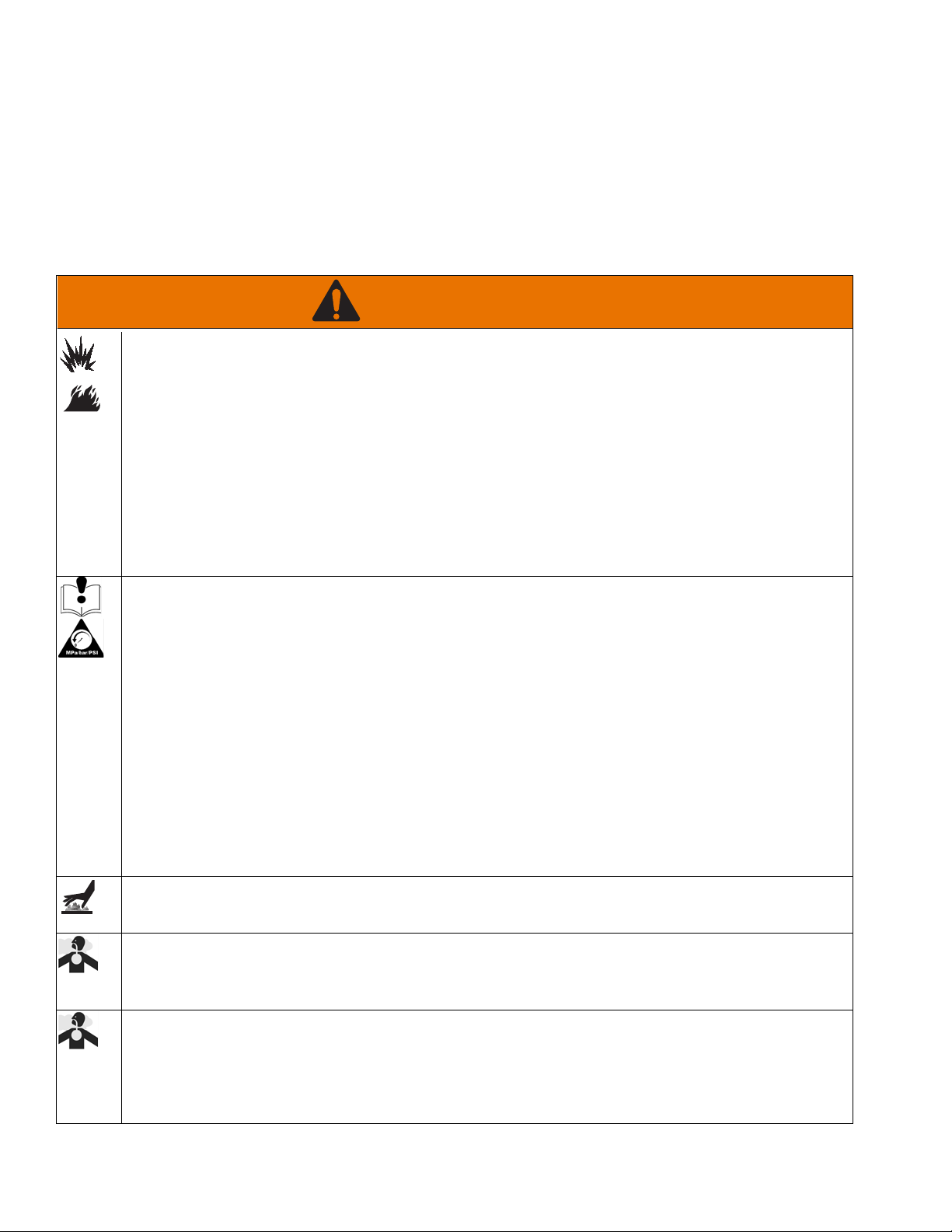
WARNING
Warnings
The following warnings are for the setup, use, grounding, maintenance, and repair of this equipment. The exclama
tion point symbol alerts you to a general warning and the hazard symbols refer to procedure-specific risks. When
these symbols appear in the body of this manual or on warning labels, refer back to these Warnings. Product-specific
hazard symbols and warnings not covered in this section may appear throughout the body of this manual where
applicable.
FIRE AND EXPLOSION HAZARD
Flammable fumes and liquids, such as propane gas, gasoline and combustible fuel, in work area can
ignite or explode. To help prevent fire and explosion:
• Do not use equipment unless fully trained and qualified.
• Do not allow open containers of flammables within 25 ft (7.6 m) of equipment. Do not operate equip
ment within 10 ft (3 m) of any structure, combustible material, or other gas cylinders.
• Shut off all burners when adding fuel to equipment.
• Close the tank shut-off valve immediately if you smell propane gas; extinguish all open flames. If gas
odor continues, keep away from equipment and immediately call the fire department.
• Follow lighting instructions for the burner and torch.
• Do not heat thermoplastic traffic marking compound material above its maximum temperature rating.
• Fire extinguisher equipment shall be present and working.
• Keep work area free of debris, including solvent, rags and gasoline.
EQUIPMENT MISUSE HAZARD
Misuse can cause death or serious injury.
• Do not leave equipment unattended.
• Keep children and animals away from work area.
• Do not exceed the maximum working pressure or temperature rating of the lowest rated system
component. See Technical Data in all equipment manuals.
• Check equipment daily. Repair or replace worn or damaged parts immediately with genuine
manufacturer’s replacement parts only.
• Do not alter or modify equipment.
• Use equipment only for its intended purpose. Call your Graco distributor for information.
• Do not fill material beyond maximum capacity.
• Route gas lines, hoses, wires and cables away from traffic areas, sharp edges, moving parts, and hot
surfaces.
• Do not kink or overbend gas lines.
• Do not override or defeat safety devices.
• Do not operate the unit when fatigued or under the influence of drugs or alcohol.
BURN HAZARD
Equipment surfaces and fluid that is heated can become very hot during operation. To avoid severe burns:
• Do not touch hot fluid or equipment.
CARBON MONOXIDE HAZARD
Exhaust contains poisonous carbon monoxide, which is colorless and odorless. Breathing carbon
monoxide can cause death.
• Do not operate in an enclosed area.
TOXIC FLUID OR FUMES HAZARD
Toxic fluids or fumes can cause serious injury or death if splashed in the eyes or on skin, inhaled, or swal
lowed.
• Read MSDSs to know the specific hazards of the fluids you are using.
• Store hazardous fluid in approved containers, and dispose of it according to applicable guidelines.
4 3A1319F
Page 5
Warnings
WARNING
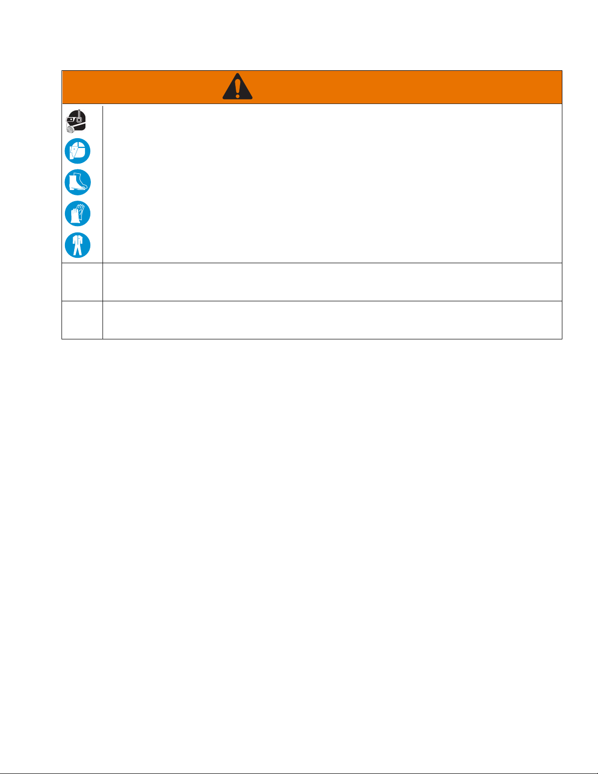
PERSONAL PROTECTIVE EQUIPMENT
Wear appropriate protective equipment when in the work area to help prevent serious injury, including eye
injury, hearing loss, inhalation of toxic fumes, and burns. This protective equipment includes but is not
limited to:
• Clothing and respirator as recommended by the fluid, material, and solvent manufacturer.
• Gloves, shoes, overalls, face shield, hat, etc. rated for elevated temperatures of at least 500° F
(260° C).
CALIFORNIA PROPOSITION 65
Exhaust from this product contains a chemical known to the State of California to cause cancer, birth
defects or other reproductive harm.
CALIFORNIA PROPOSITION 65
This product contains a chemical known to the State of California to cause cancer, birth defects or other
reproductive harm. Wash hands after handling.
3A1319F 5
Page 6
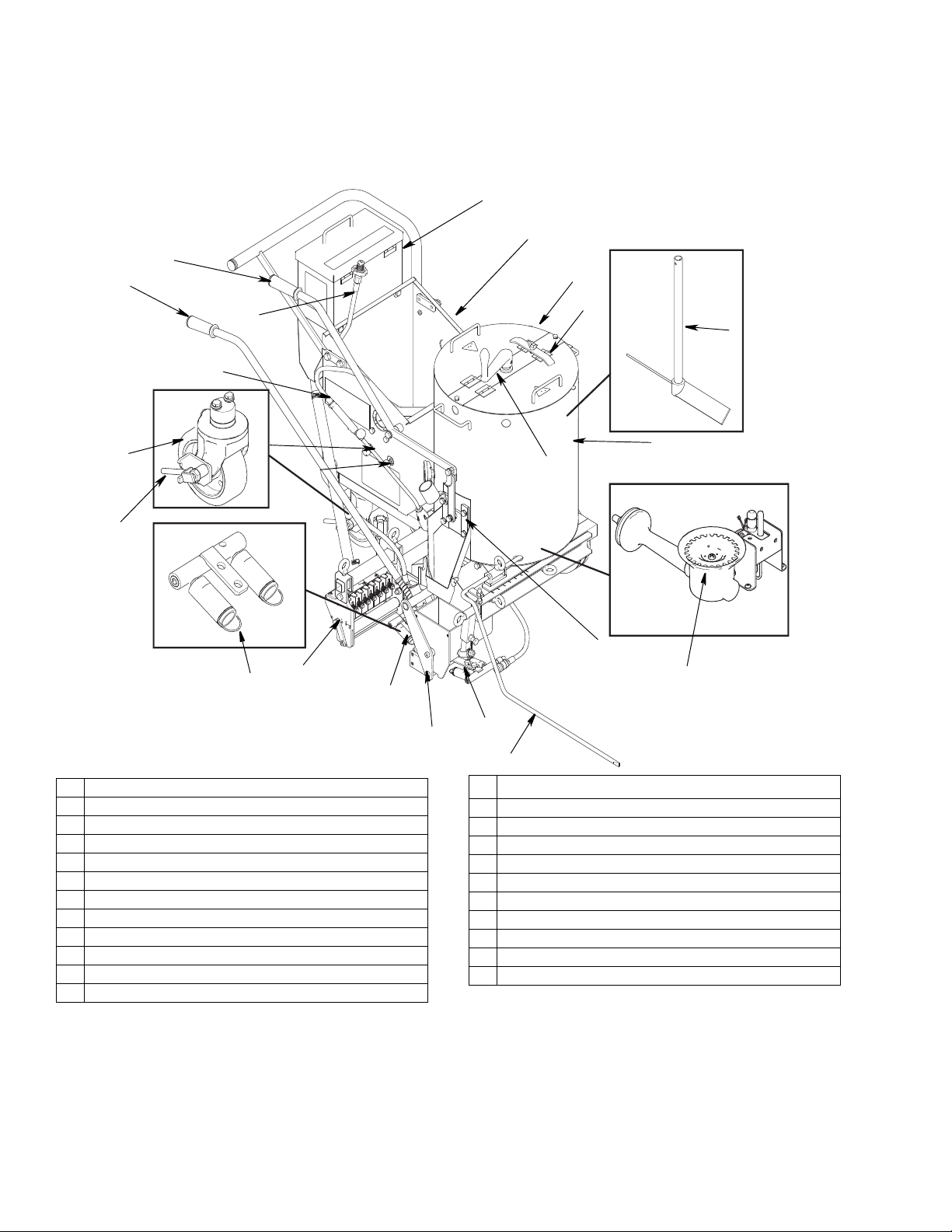
Component Identification - ThermoLazer 200
ti22640A
Q
R
P
L
K
J
F
E
C
G
H
D
B
W
A
X
U
T
S
V
M
N
ZZ
Component Identification - ThermoLazer 200
A Kettle Main Burner
B Front Screed Box Burners
C Flame Indicator
D Screed Box (FlexDie)
E Rear Screed Box Burners
F Bead Dispenser Box
G Rear Swivel Wheel
H Rear Swivel Unlock Lever
J Front Screed Box Manual Shut-Off
K Rear Screed Box Manual Shut-Off
LTorch
M Screed Box/Bead Dispenser Box Actuator
N
ControlFlow
™
Gate Valve Actuator
P Propane Tank Connector
Q Bead Hopper
R LP Gas Cylinder Holder
S Access Cover
T Agitator Crank
U Kettle
V ControlFlow Gate Valve
W Line Guide
X Agitator
ZZ Kettle Lid Lock
*LP-Gas supply cylinder not supplied by Graco. LP-Gas supply cylinder must be designed, fabricated, and marked in
accordance with specifications and regulators for LP-Gas cylinders at The U.S. Department of Transportation (DOT),
The National Standard of Canada, CAN/CSA-B339, Cylinders, Spheres, and Tubes for Transportation of Dangerous
Goods, The Transportable Pressure Vessels Regulators 2001 (S1 2001/1426), The Gas Cylinders (Pattern
Approval) Regulations 1987 (SI 1987/116)(Pattern Approval Regulations) for EEC-type cylinders under European
Directive 84/525/EEC, 84/526/EEC, and 84/527/EEC.
6 3A1319F
Page 7
Component Identification - ThermoLazer 200
CC
AA
BB
ti22642a
Component Identification - ThermoLazer 200 (continued)
AA Kettle Temperature Control Knob
BB Kettle Temperature Indicator
CC System Regulator
3A1319F 7
Page 8
Component Identification - ThermoLazer 200TC
Q
R
P
N
M
L
H
G
E
J
K
F
D
Y
X
A
B
C
Z
W
V
U
T
S
ti22640a
ZZ
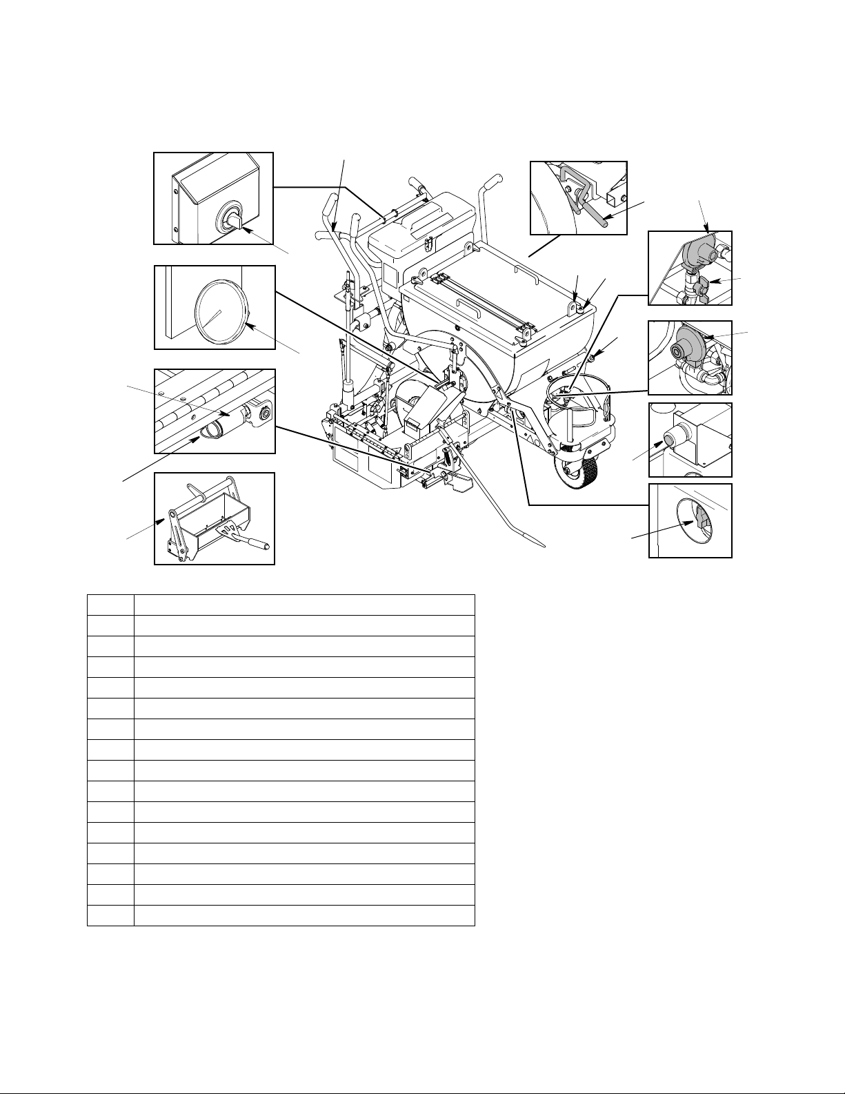
Component Identification - ThermoLazer 200TC
A Kettle Main Burner
B Kettle Pilot Burner
C Kettle Thermopile
D Front Screed Box Burners
E Flame Indicator
F Screed Box (FlexDie)
G Rear Screed Box Burners
H Bead Dispenser Box
J Rear Swivel Wheel
K Rear Swivel Unlock Lever
L Front Screed box Manual Shut-Off
M Rear Screed Box Manual Shut-Off
P Screed Box/Bead Dispense Box Actuator
Q ControlFlow Gate Valve Actuator
R Propane Tank Connector
S Bead Hopper
T LP Gas Cylinder Holder
U Access Cover
V Agitator Crank
W Kettle
X ControlFlow Gate Valve
Y Line Guide
Z Agitator
ZZ Kettle Lid Lock
NTorch
*LP-Gas supply cylinder not supplied by Graco. LP-Gas supply cylinder must be designed, fabricated, and marked in
accordance with specifications and regulators for LP-Gas cylinders at The U.S. Department of Transportation (DOT),
The National Standard of Canada, CAN/CSA-B339, Cylinders, Spheres, and Tubes for Transportation of Dangerous
Goods, The Transportable Pressure Vessels Regulators 2001 (S1 2001/1426), The Gas Cylinders (Pattern
Approval) Regulations 1987 (SI 1987/116)(Pattern Approval Regulations) for EEC-type cylinders under European
Directive 84/525/EEC, 84/526/EEC, and 84/527/EEC.
8 3A1319F
Page 9
Component Identification - ThermoLazer 200TC
DD
AA
CC
BB
ti22641a
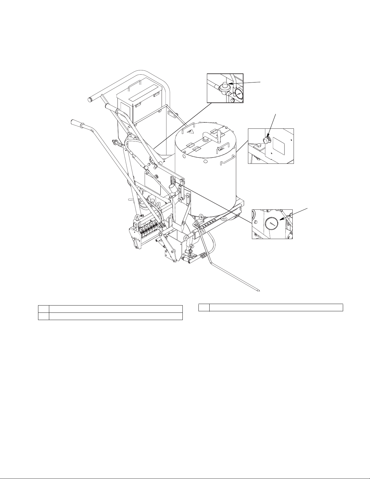
Component Identification - ThermoLazer 200TC (Continued)
AA Kettle Temperature Control Knob
BB Kettle Temperature Indicator
CC Kettle Gas Safety Valve
DD System Regulator
3A1319F 9
Page 10
Component Identification - ThermoLazer 300TC
ti24933a
U
N
S
R
AB
M
K
H
T
V
J
ALC
Z
W
P
X
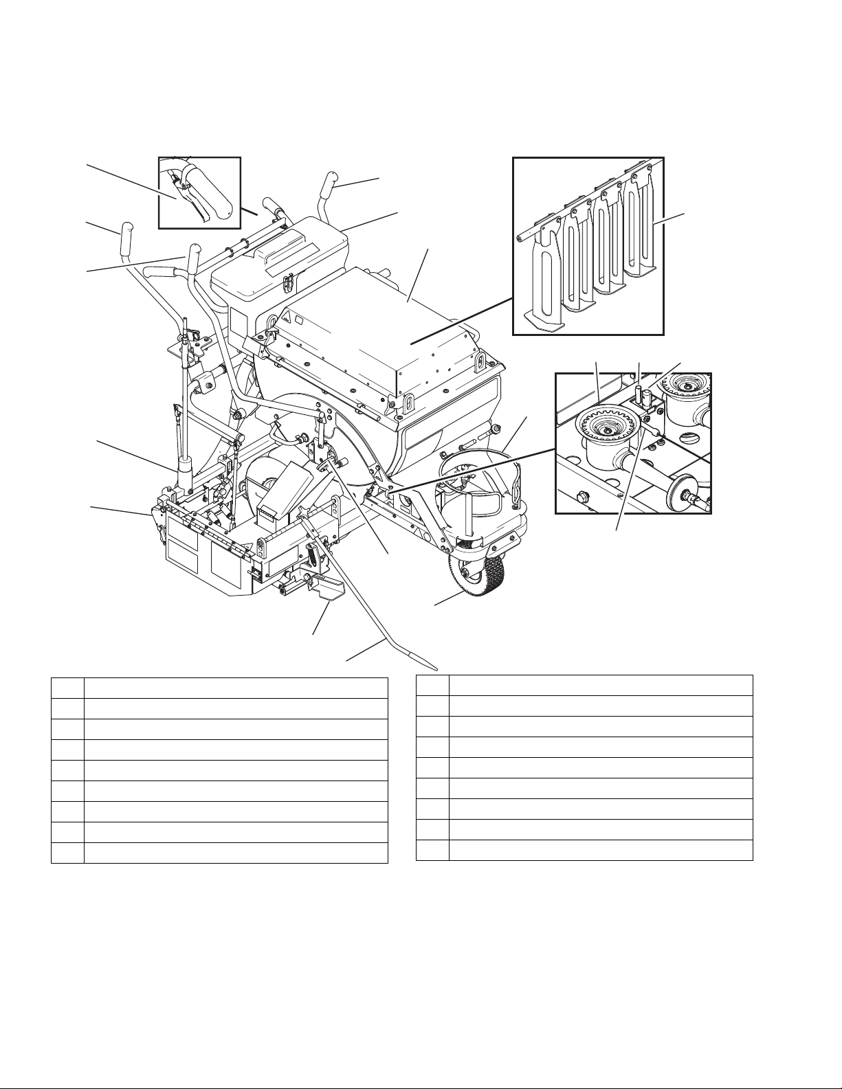
Component Identification - ThermoLazer 300TC
A Kettle Main Burners (2)
C Kettle Pilot Burner
H Line Guide
J LP Gas Cylinder Holder
K Screed Box Lever
L Kettle Thermopile
M Bead Dispenser Box
N Screed Box/Bead Dispenser Box Actuator
™
Hopper
P
SplitBead
R ControlFlow Gate Valve
S ControlFlow Gate Valve Actuator
T FatTrack Swivel Tire
U Front Swivel Unlock Lever
V Kettle Pilot Igniter Electrode
W Access Cover with Latches
X Agitator Actuator
Z Agitators
AB Torch
*LP-Gas supply cylinder not supplied by Graco. LP-Gas supply cylinder must be designed, fabricated, and marked in
accordance with specifications and regulators for LP-Gas cylinders at The U.S. Department of Transportation (DOT),
The National Standard of Canada, CAN/CSA-B339, Cylinders, Spheres, and Tubes for Transportation of Dangerous
Goods, The Transportable Pressure Vessels Regulators 2001 (S1 2001/1426), The Gas Cylinders (Pattern
Approval) Regulations 1987 (SI 1987/116)(Pattern Approval Regulations) for EEC-type cylinders under European
Directive 84/525/EEC, 84/526/EEC, and 84/527/EEC.
10 3A1319F
Page 11
Component Identification - ThermoLazer 300TC
CC
AA
BB
EE
DD
ti14146a
GG
LL
KK
PP
NN
MM
SS
QQ
UU
HH
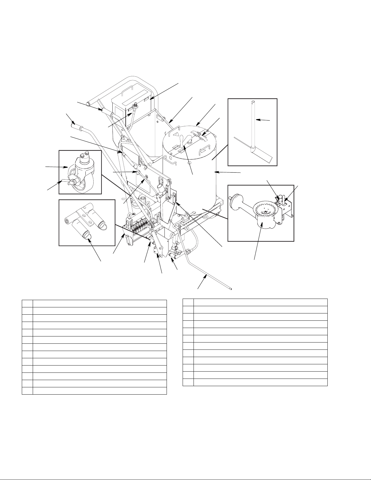
Component Identification - ThermoLazer 300TC (Continued)
AA Kettle Temperature Control Knob
BB Kettle Temperature Indicator
CC Kettle Gas Safety Valve
DD Kettle Pilot Burner Igniter
EE Screed Box (SmartDie II)
GG Front Screed Box Burners
HH Flame Indicator
KK Kettle Burners Manual Shut-Off Valve
LL Kettle Burner Regulator
MM Lifting Ring
NN Lid/Lever Latch
PP Propane Tank Connector
QQ Torch Igniter
SS Parking Brake
TT Rear Screed Box Burners
UU Screed Box Burners Regulator
3A1319F 11
Page 12
Component Identification - ThermoLazer ProMelt
ti24934a
U
N
S
R
AB
M
K
H
T
V
J
ALC
Z
W
P
X
Component Identification - ThermoLazer ProMelt
A Kettle Main Burners (2)
C Kettle Pilot Burner
H Line Guide
J LP Gas Cylinder Holder
K Screed Box Lever
L Kettle Thermopile
M Bead Dispenser Box
N Screed Box/Bead Dispenser Box Actuator
P SplitBead Hopper
*LP-Gas supply cylinder not supplied by Graco. LP-Gas supply cylinder must be designed, fabricated, and marked in
accordance with specifications and regulators for LP-Gas cylinders at The U.S. Department of Transportation (DOT),
The National Standard of Canada, CAN/CSA-B339, Cylinders, Spheres, and Tubes for Transportation of Dangerous
Goods, The Transportable Pressure Vessels Regulators 2001 (S1 2001/1426), The Gas Cylinders (Pattern
Approval) Regulations 1987 (SI 1987/116)(Pattern Approval Regulations) for EEC-type cylinders under European
Directive 84/525/EEC, 84/526/EEC, and 84/527/EEC.
R ControlFlow Gate Valve
S ControlFlow Gate Valve Actuator
T FatTrack Swivel Tire
U Front Swivel Wheel Unlock Lever
V Kettle Pilot Igniter Electrode
W Access Cover with Latches
X Agitator Actuator
Z Agitators
AB Torch
12 3A1319F
Page 13

Component Identification - ThermoLazer ProMelt
CC
AA
BB
EE
DD
ti15949a
GG
LL
KK
PP
NN
MM
RR
SS
QQ
UU
VV
HH
TT
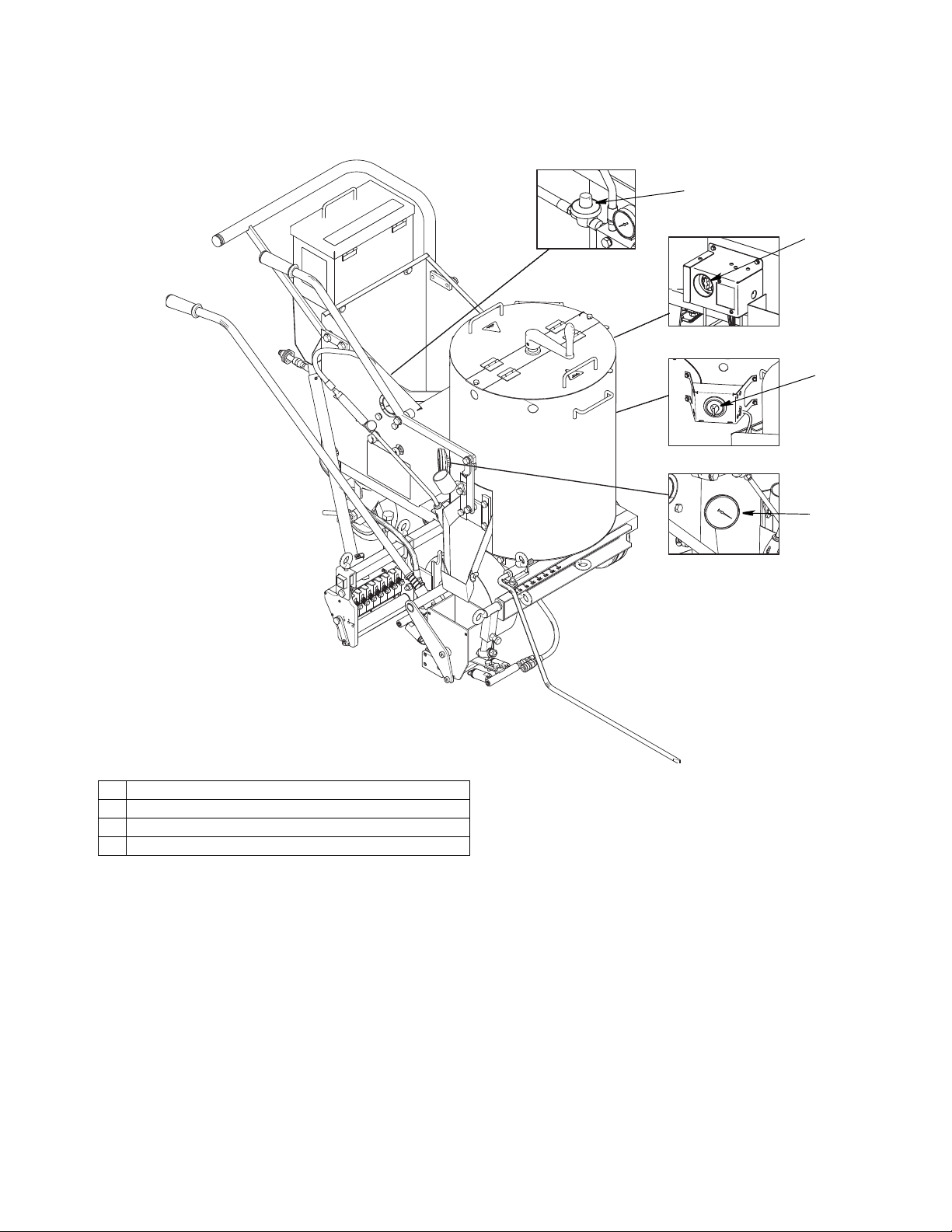
Component Identification - ThermoLazer ProMelt (Continued)
AA Kettle Temperature Control Knob
BB Kettle Temperature Indicator
CC Kettle Gas Safety Valve
DD Kettle Pilot Burner Igniter
EE Screed Box (SmartDie II)
GG Front Screed Box Burners
HH Flame Indicator
KK Kettle Burners Manual Shut-Off Valve
LL Kettle Burner Regulator
MM Lifting Ring
NN Lid/Lever Latch
PP Propane Tank Connector
QQ Torch Igniter
RR Agitator Crank
SS Parking Brake
TT Rear Screed Box Burners
UU Screed Box Burners Regulator
VV Scraper
3A1319F 13
Page 14

Important Safety Information
Burner
Kettle Burner
Front Screed
Box Burners
Rear Screed Box Burners
ti16989b
(ThermoLazer 300TC/ProMelt)
ti22561a
Burner
Burner
ti22561a
Burner
Burner
FlexDie Burners
(ThermoLazer 200/200
TC)
(All ThermoLazer units)
ti24935a
Venturi Opening
ti14411a
(All ThermoLazer units)
Important Safety Information
If you do not follow these instructions exactly, a fire
or explosion may result causing property damage,
personal injury or death.
Keep gas supply hose away from hot surfaces and
flames.
Use equipment in accordance with state and local ordi
nances with Storage, Handling and Transportation of
Liquid Petroleum Gases, ANSI/NFPA58 or CSA B149.1
If equipment has been in storage, check for insects and
insect nests on burners and Venturi tubes.
Use only vertical vapor-withdrawal LP gas cylinders
which have been designed, fabricated, tested and
marked in accordance with registration of the U.S.
Department of Transportation (DOT) or the Standard for
Cylinders, Spheres, and Tubes for the Transportation of
Dangerous Goods CAN/CSA-B337, The Transportable
Pressure Vessels Regulators 2001 (S1 2001/1426), The
Gas Cylinders (Pattern Approval) Regulations 1987 (SI
1987/116)(Pattern Approval Regulations) for EEC-type
cylinders (under European Directive 84/525/EEC,
84/526/EEC, and 84/527/EEC. Use only 20 lb to 30 lb
(9.07 kg to 13.6 kg) LP-Gas cylinders.
LP-Gas cylinder to be used only in vertical upright posi
tion as noted on agency approved LP-Gas cylinder for
proper vapor withdrawal.
Check gas supply hose connection to LP-Gas cylinder.
Make sure fitting is free of debris before connecting to
tank. Make sure gas connection is screwed completely
on and is free of leaks.
NOTE: The LP gas tanked is equipped with a POL gas
fitting. If a different sized fitting is needed, see your local
LP gas equipment supplier.
14 3A1319F
Page 15

Important Safety Information
ti16842b
ti16832b
ti14128a
Important Safety Information
Front Screed Box Burners and Rear Screed Box Burn
ers will need to be ignited to test gas lines and fitting
downstream of flame adjusting valve.
If you do not follow these instructions exactly, a fire
or explosion may result causing property damage,
personal injury or death.
BEFORE LIGHTING: Smell all around the working area
for gas. Be sure to smell next to the ground because
propane is heavier than air and will settle on the ground.
DAILY: Check for gas leaks. Use mild soap and water
solution or other approved method. Apply solution to all
gas lines and fittings then watch for gas bubbles.
NOTE: Kettle burners will need to be ignited to test gas
lines and fittings downstream of gas safety valves (CC).
Ignite burners and torch only after thoroughly checking
gas line and fittings.
WHAT TO DO IF YOU SMELL GAS OR FIND GAS
BUBBLES:
• Evacuate all unqualified personnel from area
• Do not try to ignite any burner
• Do not strike a flame
• Do not use electric fans to remove gas from area
• Do not touch any electric switch and do not use
any phone
• If leak is from a gas fitting, tighten fitting until leak
stops
• If leak is from a gas line, shut off at LP-gas cylin
der and replace gas line
• Immediately call your gas supplier from a remote
phone. Follow gas supplier’s instructions.
• If leak can not be stopped by shutting off LP-gas
cylinder shut-off valve, immediately call your gas
supplier from a remote phone. Follow gas sup
plier’s instructions.
• If you cannot reach your gas supplier call the fire
department
Use only your hand to push in or turn the kettle gas
safety valve (CC). Never use tools. If the knob will not
push in or turn by hand, do not try to repair it; call a qual
ified service technician. Attempted repair or force may
result in a fire or explosion.
Do not use this equipment if any part has been under
water. Immediately call a qualified service technician to
ThermoLazer 300TC/ProMelt shown above
inspect equipment and all components. Replace defec
tive parts only with approved manufactured parts.
3A1319F 15
Page 16

Important Safety Information
ti14412a
ti16838a
ThermoLazer 300TC shown
ThermoLazer ProMelt shown
Exhaust
Openings
ti24938a
Air Openings
Important Safety
Information
Before attempting to start equipment:
If you do not follow these instructions exactly, a fire
or explosion may result causing property damage,
personal injury or death.
All surfaces are capable of becoming extremely hot.
Be sure to always wear heat-resistant gloves and
other protective equipment rated for 500° F (260°
C). Material and unit are very hot 350° - 500° F
(177° C - 260° C). Never exceed material maximum
temperature rating.
Hot molten plastic will burn skin. Do not attempt to
remove from skin. Cool under running water and
seek medical attention.
Check gas supply hose connection to LP-gas cylinder.
Make sure fitting is free of debris before connecting to
tank. Make sure gas connection is screwed completely
on and is free of leaks.
Check to ensure that the following are closed:
• LP Gas Tank manual shut-off valve
• ControlFlow gate valve
• Front screed box burner flame adjusting valve
• Torch/flame adjusting valve
• Screed box burner flame adjusting valve
(24H622 and 24H624 only)
• Kettle gas burner manual shut-off valve
• Kettle gas safety valve
• Kettle temperature control knob (turn to “OFF”)
Check to make sure exhaust openings on kettle are not
obstructed.
See MSDS for Thermoplastic Traffic Marking
Compound.
FIRE AND EXPLOSION HAZARD
If using this unit in conjunction with LineDriver
not fill gasoline tank while burners are ignited. Allow
equipment to completely cool before refueling.
INHALATION HAZARD
Melting thermoplastic produces toxic fumes. Avoid
prolonged inhalation of fumes.
DAILY: Check all gas lines and fittings for gas leaks.
DAILY: Check gas supply hose for wear, abrasions,
cuts or leaks. Replace only with hoses recommended by
Graco.
®
, do
Check to make sure combustion air supply openings on
kettle are not obstructed.
16 3A1319F
Page 17

Lighting Instructions
ti23087a
ti14127a
ti23095a
ti23096a
ti23097a
ti23087a
Lighting Kettle Burners
NOTE: Read Important Safety Information, page
14-16.
Lighting Instructions
ThermoLazer 200
1. Open kettle door to view burner.
2. Open propane tank valve.
3. Open kettle temperature control knob (AA).
FIRE AND EXPLOSION HAZARD
If pilot ignites without depressing the gas safety valve
knob, replace gas safety valve. If gas safety valve
knob does not pop back after releasing in pilot posi
tion, STOP and replace gas safety valve. Shut off gas
at propane tank before replacing valve.
6. Turn gas safety valve knob to “ON”.
7. Turn temperature to 250° F (121° C) and observe
that main burners have ignited. Turn kettle
temperature control back to “OFF” and observe that
main burners shut off.
FIRE AND EXPLOSION HAZARD
If main burners do not ignite or shut off when rotating
temperature control knob, STOP. Shut off gas at the
propane tank. Follow diagnostic procedure in Repair
manual.
8. Turn temperature control to desired setting.
ThermoLazer 200TC
1. Open kettle door.
4. Light kettle burner with torch.
5. Regulate kettle flame as desired with kettle tem
perature control knob (AA).
3A1319F 17
Page 18

Lighting Instructions
ti14127a
ti23102a
ti23096a
ti14124a
AA
ti14131b
CC
DD
ti24935a
Kettle Burner
ti14127a
ti14129a
KK
ThermoLazer 300TC shown
ti14131a
DD
CC
2. Open propane tank valve.
3. Turn gas safety valve (CC) to “PILOT” and push in.
4. Light kettle burner with torch.
8. Turn temperature control to desired setting.
ThermoLazer 300TC/ProMelt
1. Turn temperature control knob (AA) to “OFF”.
2. Turn kettle gas safety valve (CC) to “OFF”.
3. Open kettle burner view port. (Not all models have a
view port.)
5. Continue to push in gas safety valve (CC) for
approximately 1 minute. If pilot goes out, repeat
steps 3-5 after 10 minutes.
FIRE AND EXPLOSION HAZARD
If pilot ignites without depressing the gas safety valve
knob, replace gas safety valve. If gas safety valve
knob does not pop back after releasing in pilot posi
tion, STOP and replace gas safety valve. Shut off gas
at propane tank before replacing valve.
6. Turn gas safety valve knob to “ON”.
7. Turn temperature to 250° F (121° C) and observe
that main burners have ignited. Turn kettle
temperature control back to “OFF” and observe that
main burners shut off.
FIRE AND EXPLOSION HAZARD
If main burners do not ignite or shut off when rotating
temperature control knob, STOP. Shut off gas at the
propane tank. Follow diagnostic procedure in Repair
manual.
4. Open manual shut-off valve on propane tank
located at front of unit; open kettle manual shut-off
valve (KK) below kettle and behind propane tank.
5. Turn gas safety valve (CC) to “PILOT”.
6. Push in gas safety valve knob.
7. Push kettle pilot burner igniter (DD) until pilot
ignites.
18 3A1319F
Page 19

Lighting Instructions
ti23100a
ti14128a
ti14125a
KK
ti23104a
ti14128a
ti14125a
KK
8. Continue to push in gas safety valve (CC) for
approximately 1 minute. If pilot goes out, repeat
steps 4-6 after 10 minutes.
FIRE AND EXPLOSION HAZARD
If pilot ignites without depressing the gas safety valve
knob, replace gas safety valve. If gas safety valve
knob does not pop back after releasing in pilot posi
tion, STOP and replace gas safety valve. Shut off gas
at propane tank before replacing valve.
9. Turn gas safety valve knob to “ON”.
10. Turn temperature to 250° F (121° C) and observe
that main burners have ignited. Turn kettle
temperature control back to “OFF” and observe that
main burners shut off.
FIRE AND EXPLOSION HAZARD
If main burners do not ignite or shut off when rotating
temperature control knob, STOP. Shut off gas at the
propane tank. Follow diagnostic procedure in Repair
manual.
2. Close kettle manual shut-off valve (KK) when
finished heating with kettle burners. Close manual
shut-off valve on propane tank when finished
melting and heating thermoplastic material.
NOTE: The kettle gas burner can be lit manually with a
small torch (for example: DOT 39 NRC 228/286 Cylin
der with #3 torch tip) if the battery powered pulse igniter
fails to light the pilot.
ThermoLazer 200TC
1. Turn gas safety valve to “OFF”.
11. Turn temperature control to desired setting.
Shutting Off Burner
ThermoLazer 200
1. Close kettle temperature control knob.
2. Close kettle manual shut-off valve (KK) when
finished heating with kettle burners. Close manual
shut-off valve on propane tank when finished
melting and heating thermoplastic material.
NOTE: The kettle gas burner can be lit manually with a
small torch (for example: DOT 39 NRC 228/286 Cylin
der with #3 torch tip) if the battery powered pulse igniter
fails to light the pilot.
3A1319F 19
Page 20

Lighting Instructions
ti14128a
ti14125a
KK
ti14127a
ti14138a
ThermoLazer 300TC shown
ti14139a
ti14141a
ThermoLazer 300TC/ProMelt
1. Turn gas safety valve to “OFF”.
2. Close kettle manual shut-off valve (KK) when
finished heating with kettle burners. Close manual
shut-off valve on propane tank when finished
melting and heating thermoplastic material.
NOTE: The kettle gas burner can be lit manually with a
small torch (for example: DOT 39 NRC 228/286 Cylin
der with #3 torch tip) if the battery powered pulse ignitor
fails to light the pilot.
2. Remove external torch from holder.
3. Slowly open torch flame adjusting valve and use
striker to ignite flame.
Torch Lighting Instructions
1. Open manual shut-off valve on propane tank
located at front of unit.
4. Adjust flame to desired length.
20 3A1319F
Page 21

Lighting Instructions
ti14605a
ti14128a
ti14140a
ThermoLazer 300TC shown
ti23072a
ThermoLazer 200/200TC
ThermoLazer 300TC/ProMelt
ti14142a
Shutting Off Torch
1. Fully close torch flame adjusting valve.
2. Close manual shut-off valve on propane tank when
finished melting and heating thermoplastic material.
5. Slowly open screed box burners flame adjusting
valve.
Front Screed Box Burner
Lighting Instructions
Read Important Safety Information, page 14-16.
1. Make sure screed box burners flame adjusting valve
is turned OFF.
2. Open manual shut-off valve on propane tank
located at front of unit.
3. Light torch (see Torch Lighting Instructions, page
20).
4. Open screed box access door.
6. Place torch at end of screed box burners to ignite
and use screed box burners flame adjusting valve to
adjust to desired flame.
NOTICE
If material begins to smoke or become discolored, turn
screed box burners down or off to prevent material
from burning.
7. Visually inspect to make sure flame indicators are
glowing.
Shutting Off Burners
1. Fully close screed box burners flame adjusting
valve.
3A1319F 21
2. Close manual shut-off valve on propane tank.
Page 22

Lighting Instructions
ti16990a
ThermoLazer
300
TC shown
ti14128a
Rear Screed Box Burner
Lighting Instructions
(ThermoLazer 300TC/ProMelt)
Read Important Safety Information, page 14-16.
1. Make sure screed box burners flame adjusting valve
is turned OFF.
2. Open manual shut-off valve on propane tank
located at front of unit.
3. Light torch (see Torch Lighting Instructions, page
20).
4. Slowly open screed box burners flame adjusting
valve.
5. Place torch at end of screed box burners to ignite
and use screed box burners flame adjusting valve to
adjust to desired flame.
NOTICE
If material begins to smoke or become discolored, turn
screed box burners down or off to prevent material
from burning.
6. Visually inspect to make sure flame indicators are
glowing.
Shutting Off Burners
1. Fully close screed box burners flame adjusting
valve.
2. Close manual shut-off valve on propane tank.
22 3A1319F
Page 23

Screed Box ThermoLazer 200/200TC (FlexDie)
ti122669a
Front
Rear
a
ti22670a
ti22671a
a
Z
31
ti22672a
ti22673a
10
10
Screed Box ThermoLazer 200/200TC (FlexDie)
Installation
Use extreme caution when installing and removing
screed box. Expect all equipment components and
material to be extremely hot. See MSDS for Thermo
plastic Traffic Marking Compound.
1. Shut off screed box burners.
4. Attach spring loaded handle (Z) to the yoke (31) and
turn 90 degrees to lock into place.
2. Remove bolt (a) and slide FlexDie into place.
3. Replace and tighten bolt (a).
5. Attach both gas hoses to quick release couplings
(10).
6. Re-light screed box burners as required (see
Screed Box Burner Lighting, page 21).
3A1319F 23
Page 24

Screed Box ThermoLazer 200/200TC (FlexDie)
ti122669a
Front
Rear
ti22675a
10
10
ti22676a
31
ti22677a
a
ti17047b
ti17048b
Removal
1. Shut off screed box burners.
2. Remove the two gas hoses from quick release cou
plings (10).
BURN HAZARD
Make sure to use two hands when picking up screed
box. Place one hand on yoke and one hand on rod.
3. Push in and turn spring loaded handle 90 degrees
and remove from yoke (31).
4. Remove bolt and slide FlexDie box off.
Do NOT pick up screed box with one hand and/or at
one location.
24 3A1319F
Page 25

Screed Box ThermoLazer 200/200TC (FlexDie)
c
ti22805a
ti22806a
c
ti22807a
1
ti22808a
(17, 29)
Adjustments
For optimum delivery of the thermoplastic material, make
sure the screed box is aligned to center on kettle trough.
1. Loosen two bolts (c) on mounting bracket.
2. Slide mount left or right until edge of the frame is
aligned with desired markings on bracket.
3. Tighten bolts (c) on screed box mounting bracket.
NOTE: If plates (17, 29) are not parallel to floor, loosen
screw (1) to adjust until parallel then re-tighten screw.
3A1319F 25
Page 26

Screed Box ThermoLazer 300TC/ProMelt (SmartDie II)
ti16833a
ti16846a
ti14268a
ti17300a
ti16833a
ti17300a
ti16839a
Screed Box ThermoLazer 300TC/ProMelt (SmartDie II)
Installation
Use extreme caution when installing and removing
screed box. Expect all equipment components and
material to be extremely hot. See MSDS for Thermo
plastic Traffic Marking Compound.
1. Shut off screed box burners.
5. Close and lock screed shroud door.
6. Re-light screed box burners as required (see
Screed Box Burner Lighting, page 21).
Removal
1. Shut off screed box burners.
2. Slide screed box under screed shroud and press
down on screed box lever.
3. Engage screed box rod into screed box lever.
4. Align hole of rod clevis with connecting hole in
screed box yoke and install hairpin cotter pin.
2. Remove hairpin cotter pin connecting screed box to
rod clevis.
3. Press down screed box lever.
4. Disengage screed box rod from screed box lever
and carefully remove screed box.
26 3A1319F
Page 27

BURN HAZARD
ti17047b
ti17048b
ti16835a
20 mil
.020˝
0.5 mm
ti16840a
ti17045a
Screed Box
Screed Box Runner
ti16841a
Make sure to use two hands when picking up screed
box. Place one hand on yoke and one hand on rod.
Do NOT pick up screed box with one hand and/or at
one location.
Screed Box ThermoLazer 300TC/ProMelt (SmartDie II)
2. Slide mount down until leading box edge of screed
box runner is just off of the ground surface. For best
performance, raise leading edge .020 in. (0.5 mm)
off ground surface. Scraper blade may be used to
set this depth.
Adjustment
The height and angle of the screed box can be adjusted
to ensure a solid line of material on any surface. For
optimum delivery of thermoplastic material, make sure
the screed box runner is adjusted as described.
1. Loosen two bolts on screed box mounting bracket.
3. Tighten bolts on screed box mounting bracket.
4. Spring position may be moved to a different hole.
The farthest holes provide greatest force to close
the gate.
3A1319F 27
Page 28

Screed Box Line Thickness Adjustment
X
X
mil # Turns
30 0.6
60 1.2
90 1.8
120 2.4
150 3.0
mm # Turns
0.5 0.4
1.0 0.8
1.5 1.2
2.0 1.6
ti17046a
Screed Box Line Thickness Adjustment
(All ThermoLazer units)
NOTE: 1/4 turn will change line thickness by .013 in.
(0.3 mm). Turn the line adjustment screw clockwise for a
thinner line, or counterclockwise for a thickaer line.
Typical settings on pavement: 0.060 - 0.125 in.
(0.153 - 0.318 cm).
Typical settings on metal stencil: Flush - 0.0 in. (0.0 cm).
1. Move screed box actuator to middle position. Make
sure screed box is closed and resting on the
ground. NOTE: All screed boxes are initially set at
90 mil (1.8 mm). Adjustment may be required before
first use.
2. Use a flat screwdriver to turn line adjustment screws
clockwise so that line thickness is zero.
3. Turn line adjustment screws counter-clockwise until
desired line thickness is reached.
Measure line thickness after applying thermoplastic and
adjust as necessary.
28 3A1319F
Page 29

Preparing ThermoLazer 200/200TC/300TC for Application
ti14603a
ThermoLazer 300TC shown
ti14122b
ti14123a
S
0.5 in.
ti14410a
5.0 in.
Overfill
Line
Preparing ThermoLazer 200/200TC/300TC for Application
BURN HAZARD
Keep all access covers closed and latched when equip
ment is in use.
Always secure ThermoLazer by chocking wheels when
adding thermoplastic.
1. Secure the unit by chocking wheels and applying
parking brake.
2. Make sure kettle burners and screed box burners
are lit.
3. Allow kettle to heat up before adding material. If ket
tle is completely empty, allow kettle to reach
300° - 350° F (149° - 177° C) before adding mate
rial. If kettle has material, allow material to reach
380° F (193° C) before adding material.
6. Move Gate Valve Actuator (S) to raised position and
fill screed box with melted thermoplastic material.
4. Secure ThermoLazer by chocking wheels.
5. Add thermoplastic material to kettle.
NOTE: The material gate is adjustable. The gate is
factory set at a 0.5 in. (1.3 cm) gap. You can
increase this gap for more material flow or decrease
the gap for less material flow.
7. Do not overfill material in kettle. Overfill would be
material higher than 5 in. (13 cm) below top of ket
tle.
8. Close and latch cover access doors when applying
thermoplastic.
3A1319F 29
9. Avoid bumping or impacting Thermolazer to prevent
spillage or splashing of hot material.
Page 30

Preparing ThermoLazer ProMelt for Application
ti14603a
ti15950a
ti15951a
ti15952a
(during melting)
(after material is melted)
Preparing ThermoLazer ProMelt for Application
BURN HAZARD
Keep all access covers closed and latched when
equipment is in use.
Always secure the unit by chocking wheels when
adding thermoplastic.
1. Secure the unit by chocking wheels and applying
parking brake.
7. Agitate thermoplastic until material is completely
melted. To get best agitation results, use the agita
tor crank. Use the link-connected agitator actuator
setup to agitate melted thermoplastic.
2. Make sure kettle burners and screed box burners
are lit.
3. Set Kettle Temperature Control to maximum tem
perature recommended by thermoplastic manufac
turer.
NOTE: If the kettle is empty do not allow the kettle
to heat for more than five minutes before adding
thermoplastic.
4. If the kettle has 50 lb or more of thermoplastic
already inside, allow the kettle to reach maximum
melting temperature recommended by thermoplas
tic manufacturer.
5. Unlatch kettle cover, raise cover, rotate agitator
crank to 9 o’clock position and hold at this position
using the cover latch.
8. Repeat steps 5 - 7 until kettle is filled with melted
thermoplastic.
9. Once material has been completely melted, lower
temperature to recommended material application
temperature to prevent material from overheating.
10. Start the box burner three minutes before filling
screed box with material.
11. Use torch to heat screed box and chute to applica
tion temperature if screed box and chute tempera
tures are low.
12. Release parking break and remove wheel chocks.
6. Load bag of thermoplastic directly on kettle heat
exchanger. Close cover with cover latches.
30 3A1319F
Page 31

Bead Dispenser Box
ti14123a
S
0.5 in.
ti14410a
5.0 in.
Overfill
Line
ti22649a
ti14157a
13. Move ControlFlow Gate Valve Lever (S) to raised
position and fill screed box with melted
thermoplastic material.
NOTE: The material gate is adjustable. The gate is
factory set at a 0.5 in. (1.3 cm) gap. You can
increase this gap for more material flow or decrease
the gap for less material flow.
14. Do not overfill material in kettle. Overfill would be
material higher than 5 in. (13 cm) below top of
kettle.
Bead Dispenser Box
(All ThermoLazer units)
The Bead Dispenser Box has multiple doors which can
be opened and closed to allow beads to be dispensed at
desired width patterns.
Bead flow rate can be adjusted using the Bead Flow
Rate Lever on the outside of the Bead Dispenser Box.
15. Avoid bumping or impacting the unit to prevent spill
age or splashing of hot material.
ProMelt Overheating Protection
This unit has a built-in protective device to prevent dam
age from overheating. The kettle burners may automati
cally shut down if excessive temperatures are reached.
If this happens, allow the unit to cool down for 20-30
minutes or until main kettle burners (2) reignite and
resume operation.
Adding Beads to SplitBead Hopper
Single Bead Application
(ThermoLazer 200/200TC)
1. Open SplitBead hopper door.
2. Fill hopper with beads.
Close and lock hopper door. Do not allow beads to
remain in hopper, hoses or bead dispenser for an
extended period of time. Beads will absorb moisture,
bond to adjacent beads and harden.
Single Bead Application
(ThermoLazer 300
1. Unlock and open SplitBead hopper door.
2. Fill both sides of hopper with beads.
Close and lock hopper door. Do not allow beads to
remain in hopper, hoses or bead dispenser for an
extended period of time. Beads will absorb moisture,
bond to adjacent beads and harden.
TC/ProMelt)
3A1319F 31
Page 32

Applying Material to a Surface
211
27
89
ti14564a
Double Bead Application
(ThermoLazer 300TC/ProMelt)
(Requires Installation of Double Bead Kit 24C528)
1. Fill element beads on left side (smaller chamber).
2. Fill glass beads on right side (larger chamber).
Close and lock hopper door. Do not allow beads to
remain in hopper, hoses or bead dispenser for an
extended period of time. Beads will absorb moisture,
bond to adjacent beads and harden.
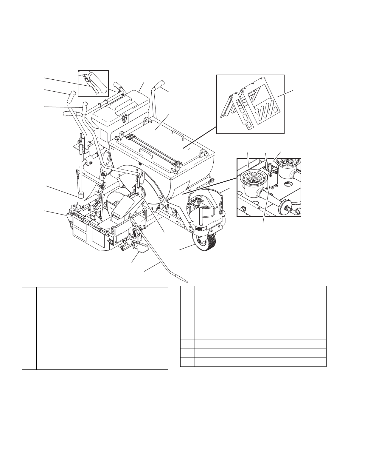
Bead Dispenser Engagement Wheel
To properly dispense beads, drive wheel (27) must be in
direct contact with tire (89). If drive wheel (27) becomes
loose and/or starts to slip, use allen wrench to tighten
set screw (211).
Applying Material to a
Surface
1. Position unit over target area and push forward in a
straight line until front wheel locks into centered
position (a slight click will be heard when wheel is
engaged). Use Line Guide to help guide the unit.
2. Pull unit back to start of target area and move
screed box into position.
3. Pull thermoplastic ControlFlow Gate Valve Actuator
(S) and fill screed box with melted material.
4. Open valve actuator gate and fill screed box to a
level 1.5 in. (3.8 cm) from top.
5. Push screed box/bead dispenser box actuator (N)
forward to deploy screed box and engage bead dis
pense wheel.
6. Push the unit forward with screed box deployed and
bead dispenser wheel engaged to apply material.
For examples of correct and incorrect material applica
tion, see Troubleshooting section in Repair manual.
32 3A1319F
Page 33

Shutting Down
ti14626a
ti14124a
ti16833a
ti14125a
ti14605a
ti14128a
1. Turn kettle gas safety valve (CC) to “OFF” position.
2. Turn temperature control knob (AA) to “OFF”.
Shutting Down
5. Fully close torch flame adjusting valve.
3. Fully close front and rear screed burner flow flame
adjusting valve OFF.
4. Close kettle manual shut-off valve.
6. Turn main gas valve on propane tank OFF.
Always store LP-Gas cylinder outside and in an
approved/secure storage locker.
This unit can be stored inside a building ONLY IF the
LP-Gas cylinder has been removed.
3A1319F 33
Page 34

Clean-Up for ThermoLazer 200/200TC/300TC
ti14603a
ti14529a
Clean-Up for ThermoLazer 200/200TC/300TC
NOTICE
Be sure to thoroughly clean all material out of screed
box and any open areas to prevent material from freez
BURN HAZARD
Never scoop out remaining melted thermoplastic from
kettle. Remaining thermoplastic can be left to harden
inside the kettle and can be remelted at a later date.
1. Secure ThermoLazer by chocking wheels.
ing moving parts of screed box. Always run all material
out of each screed box before removing. Scrape out all
remaining material before it sets within the screed box.
NOTICE
To prevent material from hardening and blocking flow,
scrape all excess material off of external surfaces after
each use, including the material trough.
NOTICE
Remove any remaining beads in the bead hopper and
bead dispenser to prevent beads from clogging hopper
and dispenser.
2. Use scraper to clean out trough and screed box.
Transporting
Remove LP-Gas supply cylinder from ThermoLazer
before transporting. Secure in an approved location and
method as authorized by local, state, federal, national,
and international agencies.
Always use the designated mounted lifting lugs when
lifting the Thermolazer. When lifting the Thermolazer
only use ANSI approved slings and equipment rated for
a minimum of 2000 lb. Always use ANSI approved
equipment for securing ThermoLazer to transporting
equipment.
34 3A1319F
Page 35

Clean-Up for ThermoLazer ProMelt
ti14603a
ti15950a
ti14529a
8. Repeat step 7.
9. Rotate agitator handle to 3 o’clock and hold at this
position by using the cover latch.
BURN HAZARD
Never scoop out remaining melted thermoplastic from
kettle without proper Personal Protective Equipment.
1. Secure unit by chocking all three wheels.
NOTE: Flow can be increased by propping up the
left rear wheel and securing unit by chocking the
other two wheels.
2. Fully engage and lock brake.
3. Rotate agitator handle to 9 o’clock and hold at this
position by using the cover latch.
10. Use small scraper to clean out trough, screed box,
and agitators.
Be sure to thoroughly clean all material out of screed
box and any open areas to prevent material from freez
ing moving parts of screed box. Always run all material
out of each screed box before removing. Scrape out all
remaining material before it sets within the screed box.
To prevent material from hardening and blocking flow,
scrape all excess material off of external surfaces after
each use.
Clean-Up for ThermoLazer ProMelt
NOTICE
NOTICE
NOTICE
Remove any remaining beads in the bead hopper and
bead dispenser to prevent beads from clogging hopper
and dispenser.
4. Turn kettle burners ON to melt material.
5. Open material gate and pour out remaining material
in a heat-resistant container.
6. Turn kettle burners OFF.
7. Use long-handled scraper tool (VV) to remove
material from inside of kettle. Start by scraping from
the top of the kettle sides and work your way down
so that as soon as the material collecting at the bot
tom begins to cool and harden you can scoop it out
of the kettle. Collect material in a heat-resistant pan.
NOTE: If material becomes too hard to scrape or
remove, reheat the kettle until the material becomes
soft again.
3A1319F 35
Transporting
Remove LP-Gas supply cylinder from the unit before
transporting. Secure in an approved location and
method as authorized by local, state, federal, national,
and international agencies.
Always use the designated mounted lifting rings when
lifting the unit. When lifting the unit, only use ANSI
approved slings and equipment rated for a minimum of
2000 lb. Always use ANSI approved equipment for
securing the unit to transporting equipment.
Page 36

Maintenance
.17 - .20 in.
ti14519b
ti24939a
2 - 3 in.
ti16991a
Maintenance
DAILY: Check gas lines and fittings for gas leaks. Use
soap and water mixture or LP-gas leak detector to
detect gas leaks.
DAILY: Make sure LP-gas only flows to burner when
safety shut-off valve knob is pressed in.
DAILY: Make sure the screed burners are burning cor
rectly.
DAILY: Check bead box dispenser drive wheel (27) and
tire (89) for foreign debris.
DAILY: Check LP-gas supply hose for abrasions, cut or
wear. Make sure hose fitting and tank fitting are free of
debris before connecting.
DAILY: Make sure kettle gas safety valve (CC) rotates
freely. Make sure valve freely moves in and out at the
“PILOT” position.
DAILY: Make sure a good spark is being produced at
the kettle pilot burner by the kettle pilot igniter electrode.
Spark gap should be 0.17 - 0.20 in. (0.43 - 0.50 cm).
DAILY: Make sure kettle main burners (A) ignite when
heat is required and shut-off when heat is not required.
WEEKLY: Grease thermoplastic flow control gate valve
guides.
WEEKLY: Check tire pressures.
WEEKLY: Check screed box bar carbide runners for
wear.
WEEKLY: Clean the kettle to remove any debris or
burnt material.
WEEKLY (or every 3000 lb of melting): Clean ProMelt
Kettle of all overheated material.
MONTHLY: Grease agitator rod ball joint ends.
DAILY: Clean ProMelt kettle screen by scraping sides
with long-handled scraper.
DAILY: Make sure kettle pilot burner (C) is burning cor
rectly. The flame should be 2 - 3 in. (5.0 - 7.6 cm) high
and blue/orange in color.
36 3A1319F
Page 37

Maintenance
86h
ti14527a
FatTrack Front Swivel Wheel
System
(ThermoLazer 300TC/ProMelt)
ANNUALLY: Tighten nut on screw under dust cap until
spring washer bottoms out. Then back off the nut 1/2 to
3/4 turns.
ANNUALLY: Tighten nut on screw until it begins to
compress spring washer. Then tighten an additional 1/4
turn.
MONTHLY: Grease the wheel bearing.
PERIODICALLY: Check caster locking pin for wear. If
pin is worn out, there will be play in the caster wheel.
Reverse or replace the pin as needed.
PERIODICALLY: Check caster wheel alignment as
necessary.
FatTrack Front Swivel Tire Alignment
Align front wheel as follows:
1. Loosen cap screw (86h).
2. Rotate front wheel fork left or right, as necessary, to
straighten alignment.
3. Tighten cap screw (86h). Push striper and let striper
roll with hands off of striper.
NOTE: If striper rolls right or left, then repeat steps 1
and 3 until striper rolls straight.
3A1319F 37
Page 38

Technical Data
Operating
(psi - bar)
Pressure
Maximum Heating
Btu/hr (kW)
Capacity
Capacity
lb (kg)
Material
Physical
Technical Data
ThermoLazer
200/200TC ThermoLazer 300TC
(24U280)
(24U281)
Fuel Liquefied Petroleum Gas (LP-gas) (propane vapor)
Gas supply maximum pressure - psi (bar) 250 (17.24)
Kettle burners 3
(0.21)
Torch 3
(0.21)
Screed box front burners 3
(0.21)
Screed box rear burners 3
(0.21)
Kettle burners (sum of burners) (1) 30,000
(8.8)
Torch 10,000
(2.93)
Screed box front burner (sum of 3 burners) 27,000
(7.9)
Screed box rear burner (sum of 4 burners) 36,000 (10.6) 36,000 (10.6) N/A 36,000 (10.6)
Total 103,000
(30.2)
with Rear
Heat
(24H622)
0.5
(0.034)
20
(1.38)
20
(1.38)
20
(1.38)
(2) 30,000
(8.8)
100,000
(29.3)
27,000
(7.9)
193,000
(56.6)
without Rear
Heat
(24H625)
0.5
(0.034)
20
(1.38)
20
(1.38)
N/A 20
(2) 30,000
(8.8)
100,000
(29.3)
27,000
(7.9)
157,000
(46.0)
ThermoLazer
ProMelt
(24H624)
3
(0.21)
20
(1.38)
20
(1.38)
(1.38)
(2) 100,000
(29.3)
100,000 (29.3)
27,000
(7.9)
263,000 (77.1)
Gas 20
(9.1)
Main kettle 200
(91)
Bead hopper 40 (18) 90 (40) - Type II glass bead
Maximum operating temperature - °F (°C) 450 (232) 450
Front tire pressure - psi (bar) N/A 45
Rear tire pressure - psi (bar) N/A 60
Weight - lb (kg) 260
(118)
Length - in. (m) 44 (1.12) 72 (1.83)
Height - in. (m) 39 (1.00) 51 (1.3)
Width - in. (m) 33 (0.84) 48 (1.22)
Igniter battery N/A AA (1.5 V)
300 (136) - Thermoplastic traffic marking
(232)
300
(136)
20
(9.1)
compound materials
450
(232)
(3.10)
(4.14)
295
(134)
(9.1, 13.6)
20,30
480
(249)
350
(159)
38 3A1319F
Page 39

Notes
Notes
3A1319F 39
Page 40

Graco Standard Warranty
Graco warrants all equipment referenced in this document which is manufactured by Graco and bearing its name to be free from defects in
material and workmanship on the date of sale to the original purchaser for use. With the exception of any special, extended, or limited warranty
published by Graco, Graco will, for a period of twelve months from the date of sale, repair or replace any part of the equipment determined by
Graco to be defective. This warranty applies only when the equipment is installed, operated and maintained in accordance with Graco’s written
recommendations.
This warranty does not cover, and Graco shall not be liable for general wear and tear, or any malfunction, damage or wear caused by faulty
installation, misapplication, abrasion, corrosion, inadequate or improper maintenance, negligence, accident, tampering, or substitution of
non-Graco component parts. Nor shall Graco be liable for malfunction, damage or wear caused by the incompatibility of Graco equipment with
structures, accessories, equipment or materials not supplied by Graco, or the improper design, manufacture, installation, operation or
maintenance of structures, accessories, equipment or materials not supplied by Graco.
This warranty is conditioned upon the prepaid return of the equipment claimed to be defective to an authorized Graco distributor for verification of
the claimed defect. If the claimed defect is verified, Graco will repair or replace free of charge any defective parts. The equipment will be returned
to the original purchaser transportation prepaid. If inspection of the equipment does not disclose any defect in material or workmanship, repairs
will be made at a reasonable charge, which charges may include the costs of parts, labor, and transportation.
THIS WARRANTY IS EXCLUSIVE, AND IS IN LIEU OF ANY OTHER WARRANTIES, EXPRESS OR IMPLIED, INCLUDING BUT NOT
LIMITED TO WARRANTY OF MERCHANTABILITY OR WARRANTY OF FITNESS FOR A PARTICULAR PURPOSE.
Graco’s sole obligation and buyer’s sole remedy for any breach of warranty shall be as set forth above. The buyer agrees that no other remedy
(including, but not limited to, incidental or consequential damages for lost profits, lost sales, injury to person or property, or any other incidental or
consequential loss) shall be available. Any action for breach of warranty must be brought within two (2) years of the date of sale.
GRACO MAKES NO WARRANTY, AND DISCLAIMS ALL IMPLIED WARRANTIES OF MERCHANTABILITY AND FITNESS FOR A
PARTICULAR PURPOSE, IN CONNECTION WITH ACCESSORIES, EQUIPMENT, MATERIALS OR COMPONENTS SOLD BUT NOT
MANUFACTURED BY GRACO. These items sold, but not manufactured by Graco (such as electric motors, switches, hose, etc.), are subject to
the warranty, if any, of their manufacturer. Graco will provide purchaser with reasonable assistance in making any claim for breach of these
warranties.
In no event will Graco be liable for indirect, incidental, special or consequential damages resulting from Graco supplying equipment hereunder, or
the furnishing, performance, or use of any products or other goods sold hereto, whether due to a breach of contract, breach of warranty, the
negligence of Graco, or otherwise.
Graco Information
For the latest information about Graco products, visit www.graco.com.
TO PLACE AN ORDER, contact your Graco distributor or call 1-800-690-2894 to identify the nearest distributor.
All written and visual data contained in this document reflects the latest product information available at the time of publication.
GRACO INC. AND SUBSIDIARIES • P.O. BOX 1441 • MINNEAPOLIS MN 55440-1441 • USA
Copyright 2011, Graco Inc. All Graco manufacturing locations are registered to ISO 9001.
Graco reserves the right to make changes at any time without notice.
For patent information, see www.graco.com/patents.
Original instructions. This manual contains English. MM 3A1319
Graco Headquarters: Minneapolis
International Offices: Belgium, China, Japan, Korea
www.graco.com
Revision F, November 2014
 Loading...