

Page 1
Installation - Parts
Solenoid
3A1162A
Changeover Kits
Increases shot accuracy and eliminates changeovers on shots that are less than 20% of
the pump volume when added to SmartWare™ Shot Dispense Kits.
For professional use only.
Not for use in explosive atmospheres.
Part 262453
Changeover kit for NXT®2200 and larger air motors.
ENG
Part 262464
Changeover kit for NXT1800 and smaller air motors.
Important Safety Instructions
Read all warnings and instructions in this
manual and the SmartWare Shot Dispense Kit
manual. Save all instructions.
Page 2
Install Changeover Kit 262453
Install Changeover Kit 262453
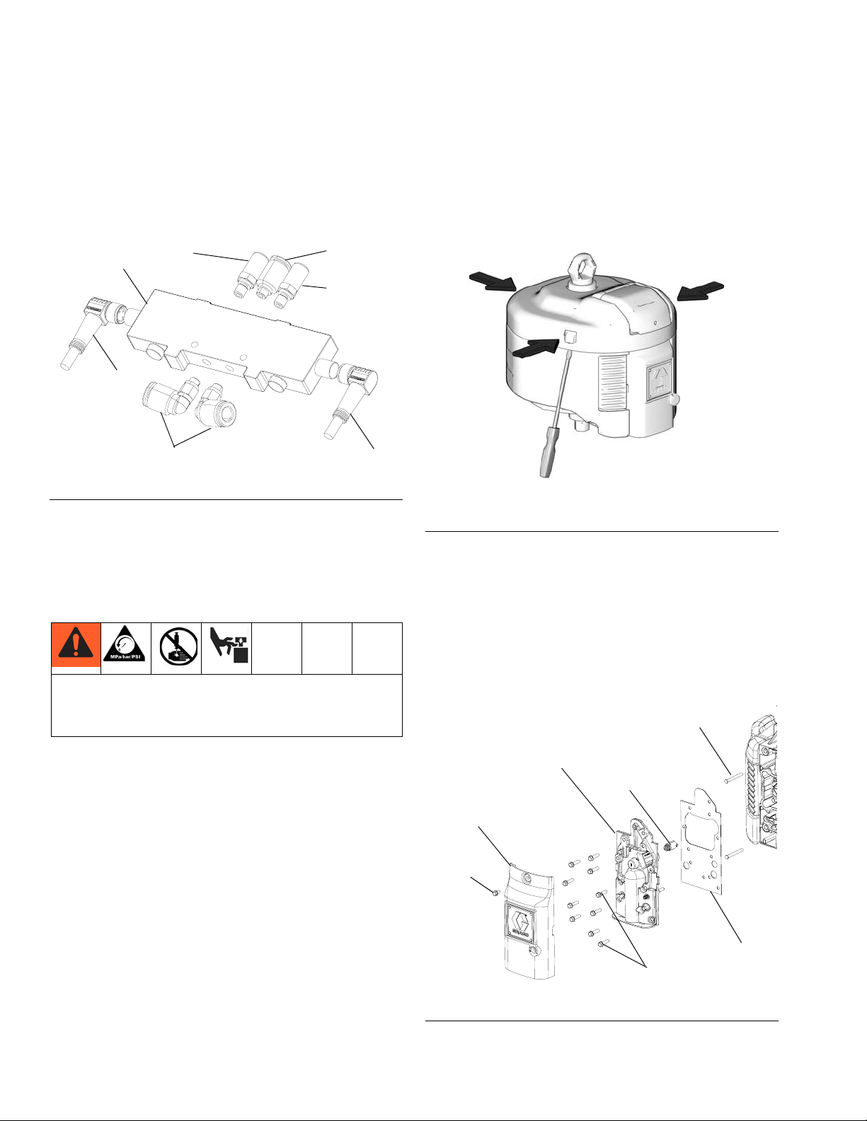
1. Assemble the air fittings onto the solenoid valve as
shown in the following figure.
3
4
FIG. 1: Assemble Fittings
2. Stop the pump at the middle of its stroke.
3. Relieve pressure. See the SmartWare Shot Dispense Kit Instructions-Parts manual for pressure
relief instructions.
7
5
6
7
4
4. Disconnect the air line to the air motor.
5. Remove the air motor top cover using a flat head
screwdriver.
ti8218b
FIG. 2: Remove Air Motor Cover
6. Remove the screw on the outer valve cover to
remove the cover.
7. Remove the ten screws from the valve cover to
remove the cover, spring-loaded detent, and gasket.
Trapped air can cause the pump to cycle
unexpectedly, which could result in serious injury
from splashing or moving parts
8. Remove both end cap retainer pins from their holes.
Retainer Pin
Valve Cover
Detent
Outer Valve Cover
Screw
Gasket
Screws
FIG. 3: Disassemble Front of Air Motor
2 3A1162A
Page 3
Install Changeover Kit 262453
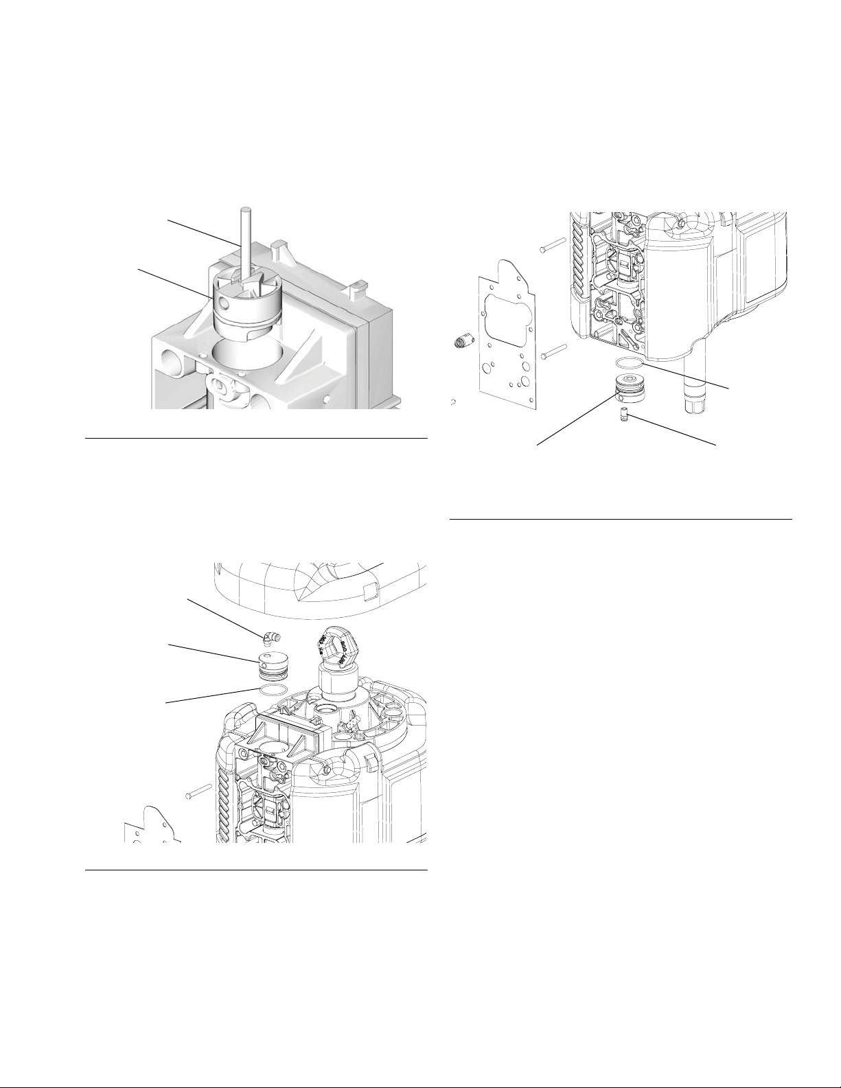
9. Invert the retainer pins and slide the heads into the
slots on the existing piston stop valves. Use the
retainer pins to pull the piston valve stops out.
Retainer Pin
Piston
Valve
Stop
ti7758a
FIG. 4: Remove Existing Piston Valve Stops
10. Install a new piston valve stop (1), o-ring (14), and
elbow fitting (20) in the top of the valve body. Apply
a liberal amount of lubricant (17) to the o-ring before
installation.
11. Install a new piston valve stop (1), o-ring (14), and
straight fitting (15) in the bottom of the valve body.
Apply a liberal amount of lubricant (17) to the o-ring
before installation.
14
1
15
FIG. 6: Install Bottom Piston Valve Stop
20
1
14
FIG. 5: Install Top Piston Valve Stop
3A1162A 3
Page 4
Install Changeover Kit 262453
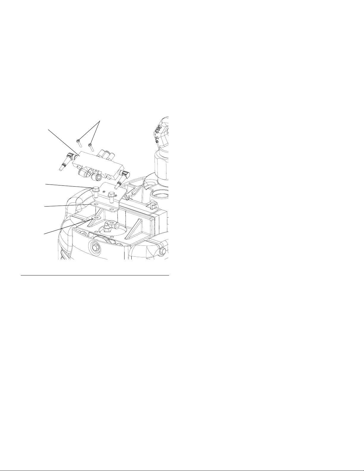
12. Install the solenoid bracket (2) to the top of the valve
body using the two mounting screws (10) and washers (11).
13. Install the solenoid valve assembly (3) to the solenoid bracket using the two solenoid valve screws
(12).
12
3
10
2
14. Connect cables and air lines as shown in F
IG. 8. Cut
air line tubes to length.
NOTE: To avoid kinks in air lines when connecting them
from the solenoid valve to the piston valve stop, use
large radius bends in the air lines and support tubing
with the supplied cable ties.
NOTE: For supply systems, ensure there is enough
cable and air line tubing to allow for full ram extension.
15. Reassemble air motor. Follow steps 6 through 3 in
reverse order.
16. Tee into your existing air supply, upstream from any
regulators, to provide air to the solenoid air supply.
Ensure there is a minimum of 70 psi (0.49 MPa, 4.9
bar).
11
FIG. 7: Install Solenoid Valve Assembly
4 3A1162A
Page 5

Install Changeover Kit 262453
9
8
Air Supply
FIG. 8: Connect Cables and Air Lines - NXT2200 and Larger Air Motors
3A1162A 5
Page 6

Install Changeover Kit 262464
Install Changeover Kit 262464
1. Assemble the air fittings onto the solenoid valve as
shown in the following figures.
NOTE: Use the following table to determine which figure
corresponds to the air motor used by your system.
Air Fitting Figures According to System and Air Motor
M02xxx M04xxx M07xxx M12xxx M18xxx
D200
Rams
S20
Rams
IG. 9
F
F
IG. 10
IG. 9 FIG. 9 FIG. 9 FIG. 9
F
IG. 10 FIG. 10, FIG. 9 FIG. 9
F
109
108
105
109
106
2. Stop the pump at the middle of its stroke.
3. Relieve pressure. See the SmartWare Shot Dispense Kit Instructions-Parts manual for pressure
relief instructions.
Trapped air can cause the pump to cycle
unexpectedly, which could result in serious injury
from splashing or moving parts
4. Disconnect the air line to the air motor.
5. Remove the existing snap ring from each end of the
air valve.
6. Use the piston to push the existing air valve plug out
of each end.
7. Remove the existing o-rings from each end.
107
FIG. 9: Assemble Fittings
109
105
106
107
FIG. 10: Assemble Fittings
107
Snap Ring
106
O-ring
Air Valve Plug
109
FIG. 11: Remove Existing Air Valve Plug
106
6 3A1162A
Page 7

Install Changeover Kit 262464
8. Install the top o-ring (116 or 117) air valve plug (101
or 102), snap ring (118 or 119), and elbow fitting
(107) in the top of the valve body. Apply a liberal
amount of the supplied lubricant to the o-rings
before installation. Refer to F
IG. 12 and FIG. 13.
M02xxx and M04xxx
107
118
101
116
9. Install the bottom o-ring (116 or 117), air valve plug
(101 and 102), snap ring (118 and 119), and elbow
fitting (107) in the bottom of the valve body. Apply a
liberal amount of the supplied lubricant to the
o-rings before installation. Refer to F
IG. 14 and FIG.
15.
116
101
14
118
107
1
M02xxx and M04xxx
15
FIG. 12: Install Top Air Valve Plug
M07xxx, M12xxx, and M18xxx
107
119
102
117
FIG. 13: Install Top Air Valve Plug
FIG. 14: Install Bottom Air Valve Plug
117
102
119
107
M07xxx, M12xxx, and M18xxx
FIG. 15: Install Bottom Air Valve Plug
3A1162A 7
Page 8

Install Changeover Kit 262464
10. Mount the solenoid valve assembly (105) onto the
correct bracket (103 or 104) for your air motor using
the screws (114) and washers (115) as shown in
F
IG. 16 and FIG. 17.
11. Install the solenoid bracket (103 or 104) to the back
of the air motor body using the two mounting screws
(112) and washers (113) as shown in F
F
IG. 17.
IG. 16 and
NOTE: Use the following table to determine which figure
corresponds to the air motor used by your system.
D200
Rams
S20
Rams
105
Solenoid Bracket Figures According to
System and Air Motor
M02xxx M04xxx M07xxx M12xxx M18xxx
IG. 16
F
F
IG. 16
FIG. 16 FIG. 16 FIG. 16 FIG. 16
FIG. 16 FIG. 16 FIG. 17 FIG. 17
114
115
113
112
103
114
105
115
FIG. 17: Install Solenoid Valve Assembly
12. Connect cables and air lines as shown in F
IG. 18.
Cut air line tubes to length.
13. Tee into your existing air supply, upstream from any
regulators, to provide air to the solenoid air supply.
Ensure there is a minimum of 70 psi (0.49 MPa, 4.9
bar).
104
112 113
FIG. 16: Install Solenoid Valve Assembly
8 3A1162A
Page 9

Install Changeover Kit 262464
111
110
Air Supply
FIG. 18: Connect Cables and Air Line - NXT1800 and Smaller Air Motors
3A1162A 9
Page 10

Parts
Parts
Kit 262453
For NXT2200 and larger air motors
Ref. Part Description Qty.
1 16F602 STOP, valve piston, ported 2
2 BRACKET, solenoid mount 1
3 16F612 VALVE, solenoid 1
4 124661 CABLE, changeover solenoid 2
5 124745 FITTING, elbow, swivel; 10-32x1/4 2
6 124746 FITTING, straight; 10-32x1/4 1
7 124795 MUFFLER; 10-32 thread 2
8 124273 CONNECTOR, splitter 1
9 124415 CABLE; 5 pin, mf, 3.0m 1
10 107257 SCREW, thread forming 2
11 115814 WASHER, flat, sst 2
12 107390 SCREW, machined, pan head 2
13 100272 WASHER, lock 2
14 108014 O-RING 2
15 C19405 FITTING, connector, male 1
16 C12509 TUBE; nylon, round, 15 ft. 18 103473 STRAP, tie, wire 8
20 112698 ELBOW, male, swivel 1
Kit 262464
For NXT1800 and smaller air motors
Ref. Part Description Qty.
101 16F837 PLUG, air valve, ported, small 2
102 16F839 PLUG, air valve, ported, medium 2
103 BRACKET, solenoid mount 1
104 BRACKET, solenoid mount 1
105 16F612 VALVE, solenoid 1
106 124661 CABLE, changeover solenoid 2
107 124745 FITTING, elbow, swivel; 10-32x1/4 5
108 124746 FITTING, straight; 10-32x1/4 1
109 124795 MUFFLER; 10-32 thread 2
110 124273 CONNECTOR, splitter 1
111 124415 CABLE; 5 pin, mf, 3.0m 1
112 15V909 SCREW; m8 x 12 2
113 100133 WASHER, lock 2
114 107390 SCREW, machined, pan head 2
115 100272 WASHER, lock 2
116 514279 O-RING; 018 buna 2
117 103255 O-RING 2
118 15M269 RING, snap, internal 2
119 15M271 RING, retaining 2
120 C12509 TUBE; nylon, round, 15 ft. 122 103473 STRAP, tie, wire 8
10 3A1162A
Page 11

Parts
3A1162A 11
Page 12

Graco Standard Warranty
Graco warrants all equipment referenced in this document which is manufactured by Graco and bearing its name to be free from defects in
material and workmanship on the date of sale to the original purchaser for use. With the exception of any special, extended, or limited warranty
published by Graco, Graco will, for a period of twelve months from the date of sale, repair or replace any part of the equipment determined by
Graco to be defective. This warranty applies only when the equipment is installed, operated and maintained in accordance with Graco’s written
recommendations.
This warranty does not cover, and Graco shall not be liable for general wear and tear, or any malfunction, damage or wear caused by faulty
installation, misapplication, abrasion, corrosion, inadequate or improper maintenance, negligence, accident, tampering, or substitution of
non-Graco component parts. Nor shall Graco be liable for malfunction, damage or wear caused by the incompatibility of Graco equipment with
structures, accessories, equipment or materials not supplied by Graco, or the improper design, manufacture, installation, operation or
maintenance of structures, accessories, equipment or materials not supplied by Graco.
This warranty is conditioned upon the prepaid return of the equipment claimed to be defective to an authorized Graco distributor for verification of
the claimed defect. If the claimed defect is verified, Graco will repair or replace free of charge any defective parts. The equipment will be returned
to the original purchaser transportation prepaid. If inspection of the equipment does not disclose any defect in material or workmanship, repairs will
be made at a reasonable charge, which charges may include the costs of parts, labor, and transportation.
THIS WARRANTY IS EXCLUSIVE, AND IS IN LIEU OF ANY OTHER WARRANTIES, EXPRESS OR IMPLIED, INCLUDING BUT NOT LIMITED
TO WARRANTY OF MERCHANTABILITY OR WARRANTY OF FITNESS FOR A PARTICULAR PURPOSE.
Graco’s sole obligation and buyer’s sole remedy for any breach of warranty shall be as set forth above. The buyer agrees that no other remedy
(including, but not limited to, incidental or consequential damages for lost profits, lost sales, injury to person or property, or any other incidental or
consequential loss) shall be available. Any action for breach of warranty must be brought within two (2) years of the date of sale.
GRACO MAKES NO WARRANTY, AND DISCLAIMS ALL IMPLIED WARRANTIES OF MERCHANTABILITY AND FITNESS FOR A
PARTICULAR PURPOSE, IN CONNECTION WITH ACCESSORIES, EQUIPMENT, MATERIALS OR COMPONENTS SOLD BUT NOT
MANUFACTURED BY GRACO. These items sold, but not manufactured by Graco (such as electric motors, switches, hose, etc.), are subject to
the warranty, if any, of their manufacturer. Graco will provide purchaser with reasonable assistance in making any claim for breach of these
warranties.
In no event will Graco be liable for indirect, incidental, special or consequential damages resulting from Graco supplying equipment hereunder, or
the furnishing, performance, or use of any products or other goods sold hereto, whether due to a breach of contract, breach of warranty, the
negligence of Graco, or otherwise.
FOR GRACO CANADA CUSTOMERS
The Parties acknowledge that they have required that the present document, as well as all documents, notices and legal proceedings entered into,
given or instituted pursuant hereto or relating directly or indirectly hereto, be drawn up in English. Les parties reconnaissent avoir convenu que la
rédaction du présente document sera en Anglais, ainsi que tous documents, avis et procédures judiciaires exécutés, donnés ou intentés, à la suite
de ou en rapport, directement ou indirectement, avec les procédures concernées.
Graco Information
For the latest information about Graco products, visit www.graco.com.
TO PLACE AN ORDER, contact your Graco distributor or call to identify the nearest distributor.
Phone: 612-623-6921 or Toll Free: 1-800-328-0211 Fax: 612-378-3505
All written and visual data contained in this document reflects the latest product information available at the time of publication.
Graco reserves the right to make changes at any time without notice.
Original instructions. This manual contains English. MM 3A1162
Graco Headquarters: Minneapolis
International Offices: Belgium, China, Japan, Korea
GRACO INC. P.O. BOX 1441 MINNEAPOLIS, MN 55440-1441
Copyright 2010, Graco Inc. is registered to ISO 9001
www.graco.com
 Loading...