

Page 1
Instructions
™
HFR
Gateway Module Kits
For external control of the HFR system. For professional use only. Not approved for use in
European explosive atmosphere locations.
Single Discrete Gateway Module Kit, 24F843
Dual Discrete Gateway Modules Kit, 24F844
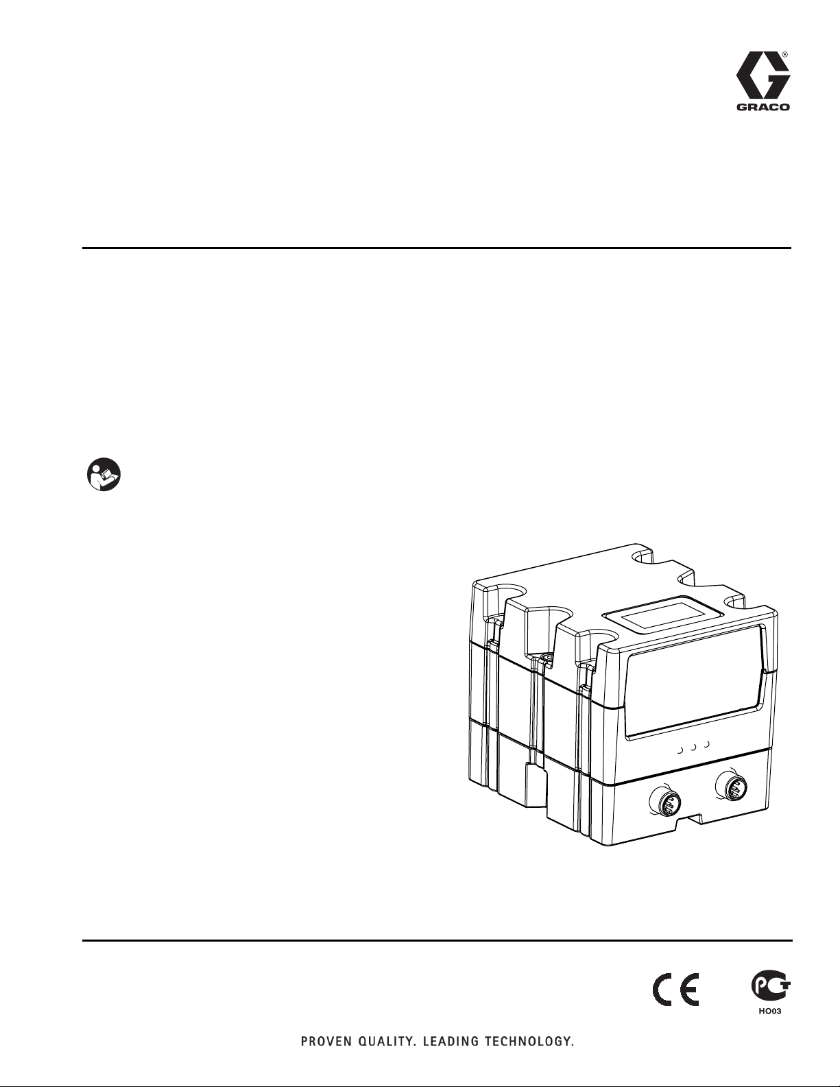
Discrete Gateway Module, 24G830
Important Safety Instructions
Read all warnings and instructions in the
HFR operation manual 313997. Save all
instructions.
Discrete
3A1149D
ENG
r_24B681_2B9904_1b
Page 2

Related Manuals
Contents
Related Manuals . . . . . . . . . . . . . . . . . . . . . . . . . . . 2
Overview . . . . . . . . . . . . . . . . . . . . . . . . . . . . . . . . . . 3
DGM Presence . . . . . . . . . . . . . . . . . . . . . . . . . . 3
Automation Presence . . . . . . . . . . . . . . . . . . . . . 3
Typical Installation . . . . . . . . . . . . . . . . . . . . . . . . . 4
Component Identification . . . . . . . . . . . . . . . . . . . . 5
Module Requirements . . . . . . . . . . . . . . . . . . . . . . . 6
I/O Setup . . . . . . . . . . . . . . . . . . . . . . . . . . . . . . . . . . 6
DGM Digital Input Overview . . . . . . . . . . . . . . . . 7
DGM Digital Outputs Overview . . . . . . . . . . . . . . 8
DGM Analog Inputs Overview . . . . . . . . . . . . . . . 9
DGM Analog Outputs Overview . . . . . . . . . . . . . 9
Primary DGM Pin Assignments . . . . . . . . . . . . 10
Secondary DGM Pin Assignments . . . . . . . . . . 12
Setup . . . . . . . . . . . . . . . . . . . . . . . . . . . . . . . . . . . . 14
Operation . . . . . . . . . . . . . . . . . . . . . . . . . . . . . . . . 16
Primary DGM Digital Inputs . . . . . . . . . . . . . . . 16
Primary DGM Digital Outputs . . . . . . . . . . . . . . 18
Primary DGM Analog Inputs . . . . . . . . . . . . . . . 19
Primary DGM Analog Outputs . . . . . . . . . . . . . 20
Secondary DGM I/O Overview . . . . . . . . . . . . . 21
Secondary DGM Digital Inputs . . . . . . . . . . . . . 22
Secondary DGM Digital Outputs . . . . . . . . . . . . 22
Secondary DGM Analog Inputs . . . . . . . . . . . . 23
Secondary DGM Analog Outputs . . . . . . . . . . . 24
Timing Diagrams . . . . . . . . . . . . . . . . . . . . . . . . . . 25
Heartbeat . . . . . . . . . . . . . . . . . . . . . . . . . . . . . 25
Activate System Stop Button . . . . . . . . . . . . . . . 25
System Requests . . . . . . . . . . . . . . . . . . . . . . . 26
Select an Operating Mode or Shot Number . . . 26
Change Setpoint . . . . . . . . . . . . . . . . . . . . . . . . 27
Toggle On/Off . . . . . . . . . . . . . . . . . . . . . . . . . . 27
Shot Mode Dispense . . . . . . . . . . . . . . . . . . . . 28
Shot Mode Dispense and Termination . . . . . . . 28
Operator Mode Dispense . . . . . . . . . . . . . . . . . 29
Maintenance . . . . . . . . . . . . . . . . . . . . . . . . . . . . . . 30
Install Upgrade Token . . . . . . . . . . . . . . . . . . . . 30
Check Cable Connections . . . . . . . . . . . . . . . . . 30
Troubleshooting . . . . . . . . . . . . . . . . . . . . . . . . . . . 31
Diagnostic Information . . . . . . . . . . . . . . . . . . . . 31
Fault Code Bit Pattern Table . . . . . . . . . . . . . . . 31
Parts . . . . . . . . . . . . . . . . . . . . . . . . . . . . . . . . . . . . 34
Accessories . . . . . . . . . . . . . . . . . . . . . . . . . . . . . . 35
Technical Data . . . . . . . . . . . . . . . . . . . . . . . . . . . . 35
Graco Standard Warranty . . . . . . . . . . . . . . . . . . . 36
Graco Information . . . . . . . . . . . . . . . . . . . . . . . . . 36
Related Manuals
The following manuals are available at www.graco.com.
Manuals are in English.
Part Description
313997 HFR Operation
313998 HFR Repair-Parts
2 3A1149D
Page 3

Overview
Overview
This Discrete Gateway Module (DGM) allows the user to
control an HFR through an external control device such
as a PLC. The DGM will operate in conjunction with the
existing Advanced Display Module (ADM) such that both
devices can be used to control the machine. Each HFR
can be controlled using up to two DGM’s which will be
referred to as the primary and secondary DGM’s.
The primary DGM allows the user to monitor and control
general machine functions. This includes the following
capabilities:
• Dispensing
• Operating mode selection
• Shot selection
• Fault code monitoring
• Fault acknowledgment
• Pump parking
• Monitoring working pressures of each pump
• Monitoring the combined flow or B (Blue) pump
pressure while dispensing
• System Stop button
• Changing the combined flow or B (Blue) pump pressure in operator mode
Automation Presence
The primary DGM includes a heartbeat monitor. This
serves as a verification that the PLC and DGM are communicating. In the event that the PLC becomes unresponsive, the DGM will terminate any active dispenses
and set the machine to disabled mode.
The secondary DGM is used for monitoring and controlling the temperature conditioning components. These
features include:
• Monitoring which conditioning zones are enabled
• Monitoring temperatures of enabled zones
• Turning on or off the enabled zones
• Changing temperature setpoints of enabled zones
NOTE: Changing temperature setpoints is only available
on machines with 2nd generation ADMs. 2nd generation
ADMs are distinguishable by having only 2 cable connections on the bottom of the ADM. 1st generation
ADMs have 4 cable connections.
DGM Presence
The DGM will broadcast a heartbeat to the HFR every
5 seconds. In the event that the DGM fails to broadcast
a heartbeat after 10 seconds, the system will go into disabled mode.
The system can be taken out of disabled mode after
acknowledging the alarm on the ADM.
3A1149D 3
Page 4
Typical Installation
Typical Installation
D
A
B
1
2
C
F
FIG. 1
Key:
A Discrete Gateway Module (DGM)
B Breakout Board
CCAN Cables
D 78 Pin D-Sub Cables (Male to Female)
E Ground screw
F Connects to HFR
G Ferrite Suppressor
G
E
r_24F843_3A1149_1b
4 3A1149D
Page 5
Component Identification
Component Identification
AB
AF
AA
AE
r_24B681_2B9904_1b
AC
AJ
r_24B681_2B9904_2b
AD
AG
AH
FIG. 2:
Key:
AA Discrete Gateway Module (DGM)
AB Base
AC Module Connection Screws
AD Access Cover
AE Module Status LEDs
AF CAN Connectors
AG Rotary Switch
AH Token Slot
AJ D-Sub Connection
r_24B681_2B9904_4b
3A1149D 5
Page 6
Module Requirements
Module Requirements
Each DGM requires a 9-30 VDC NEC Class 2 power
supply. This is supplied to the DGM through pins 27, 51,
68, 69 on the D-Sub connection. Ground from this supply should only be connected to pin 70 of the D-Sub
connection.
I/O Setup
NOTE: Each DGM is set as the primary or secondary
DGM by setting the rotary switch (AG) position. See
Setup on page 14.
NOTICE
To avoid ground loops and noise immunity issues, do
not ground the shield of the D-sub connector cable.
The shield is already grounded through the mounting
screw on the base of the DGM. If using a breakout
board, do not make any connections to the pins with
ground symbols.
See the Digital and Analog I/O Overview sections beginning on the following page for I/O setup details. See the
Primary DGM Pin Assignments and Secondary DGM
Pin Assignments sections beginning on page 10 for
individual pin assignments.
1
21
20
39
7859
F
IG. 3: D-sub Connector - Pin References
40
60
6 3A1149D
Page 7
I/O Setup
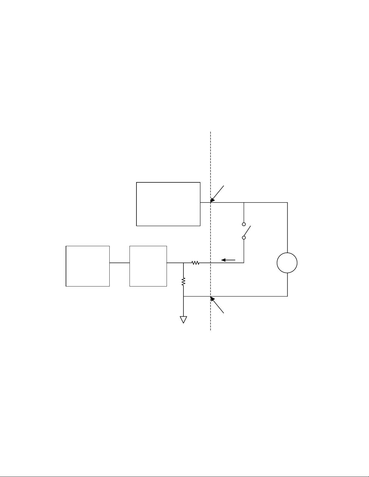
DGM Digital Input Overview
The digital inputs function only when power is supplied to pin 51 and there is a ground connection to pin 70. The digital input is rated at 0-30 VDC, and requires an NEC Class 2 power supply connected to pin 51. The DGM provides
optical isolation as shown in the following illustration.
• Pins: 52 – 59, 71-78
• Type: Sinking
• Maximum current draw: 3.6 mA
Discrete Gateway
Discrete Gateway
Customer Automation
Customer Automation
D-Sub Pin 51 (Isolated
D-Sub Pin 51 (Isolated
Logic Supply)
Logic Supply)
Microcontroller
Microcontroller
Isolated Logic ICs
Isolated Logic ICs
Optical
Optical
Isolator
Isolator
Digital Input
D-Sub Pin 70
D-Sub Pin 70
(Isolated Ground)
(Isolated Ground)
24VDC
24VDC
3A1149D 7
Page 8
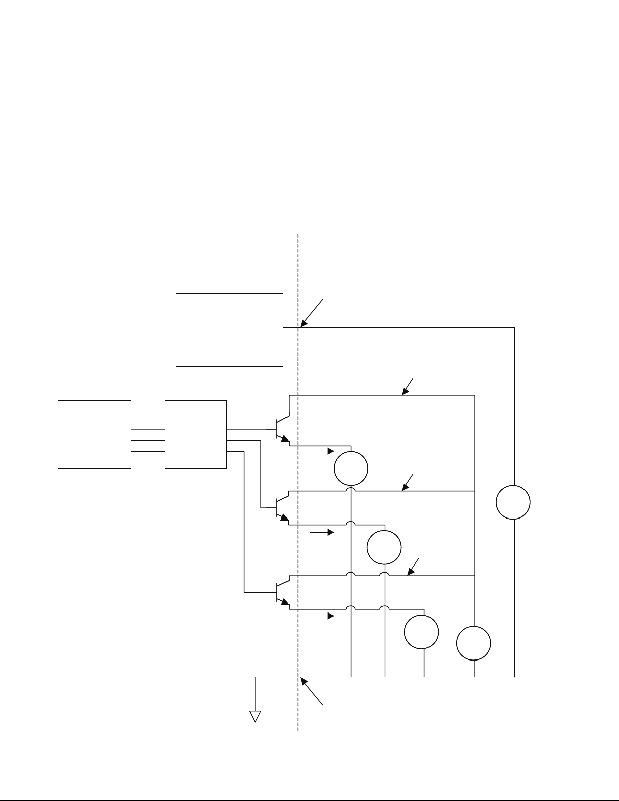
I/O Setup
DGM Digital Outputs Overview
The digital outputs function only when power is supplied to pins 27, 68, and 69 and there is a ground connection to
pin 70. The digital output is rated at 0-30 VDC, and requires an NEC Class 2 power supply connected to pin 27 for
supply bank 1, pin 69 for supply bank 2, and pin 68 for supply bank 3. The DGM provides optical isolation as shown
in the following illustration.
• Pins: 9-20, 28-39
• Type: Sourcing
• Maximum continuous current output: 350 mA
(sourced from customer supply)
• Recommended continuous current: 100 mA
Microcontroller
Disc rete Gate way
Isolated Logic ICs
Optical
Isolator
Customer Automation
D-Sub Pin 51 (Isolated
Logic Supply)
D-Sub
Pin 27
Digital
Output
1-8
D-Sub
Pin 69
LOADLOAD
Digital
Output
9-16
Digital Input
Supply Bank 1
Digital Input
Supply Bank 2
24VDC24VDC
LOADLOAD
D-Sub
Pin 68
Digital
Output
17-24
D-Sub Pin 70
(Isolated Ground)
Digital Input
Supply Bank 3
LOADLOAD
24VDC24VDC
8 3A1149D
Page 9
I/O Setup
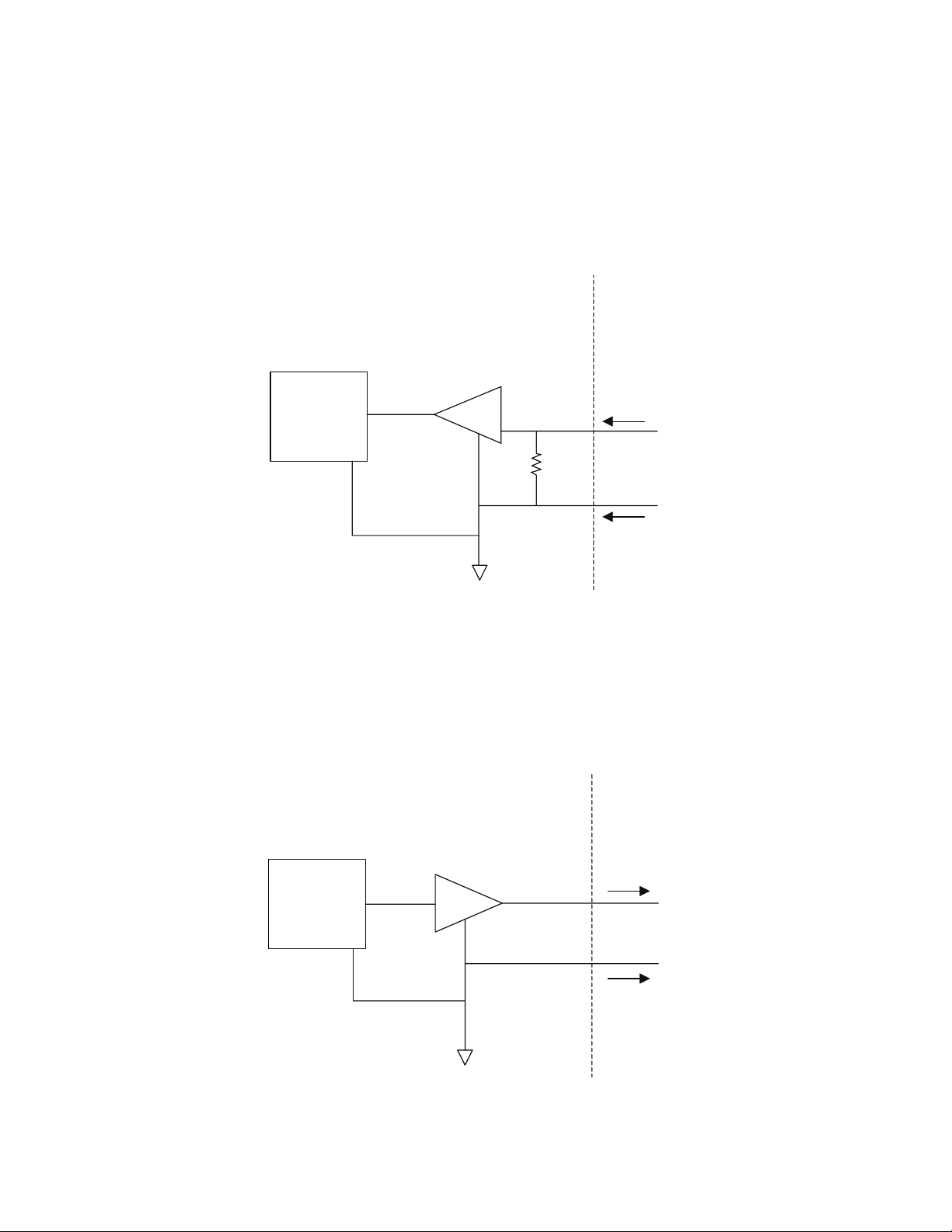
DGM Analog Inputs Overview
The analog inputs function only when the DGM is connected to a power supply through the CAN connection; see
Setup, page 14. Each analog input has a corresponding reference (ground) pin.
• Type: Sinking
• Voltage Rating: 0-10 Vdc
• Input Impedance: 20 k
Ω
Discrete Gateway Customer Automation
Microcontroller
Analog Input +
+
20kΩ
-
Analog Input -
DGM Analog Outputs Overview
The analog outputs function only when the DGM is connected to a power supply through the CAN connection; see
Setup on page 14. Each analog output has a corresponding reference (ground) pin.
• Type: Sourcing
• Voltage Rating: 0-10 Vdc, 10 mA at 10 Vdc
Discrete Gateway Customer Automation
Analog Output +
Microcontroller
0-10VDC @10mA
+
-
Analog Output -
3A1149D 9
Page 10
I/O Setup
Primary DGM Pin Assignments
Pin
Number
52 1 PLC to DGM Heartbeat
53 2 Dispense Request / Terminate
54 3 System Stop
55 4 Acknowledge Active Error
56 5 Set Operating Mode, Bit 2
57 6 Set Operating Mode, Bit 1
58 7 Set Operating Mode, Bit 0
59 8 Accept Operating Mode
71 9 Select Shot, Bit 6 (Shot Mode)
72 10 Select Shot, Bit 5 (Shot Mode)
73 11 Select Shot, Bit 4 (Shot Mode)
74 12 Select Shot, Bit 3 (Shot Mode),
75 13 Select Shot, Bit 2 (Shot Mode),
76 14 Select Shot, Bit 1 (Shot Mode),
77 15 Select Shot, Bit 0 (Shot Mode),
78 16 Accepted Selected Shot (Shot
DGM Digital
Inputs Functional Description
(Shot, Operator modes), or
Start/Stop Recirculation
(Standby Mode)
Change
or Enable Dispensing (Active
Low)
or Enable ADM (System in Disabled mode)
or Lock/Unlock the Dispense
Valve (Standby Mode)
or Open/Close Dispense
Valve (Standby Mode)
Mode), or Accepted Pressure/Flow (Operator Mode), or
Park Pump (Standby Mode)
Pin
Number
9 1 DGM to PLC Heartbeat
10 2 Ready to Dispense
11 3 Dispense in Progress
12 4 Requested Flow Rate/Pres-
13 5 Dispense Mode Selected:
14 6 Error Present
15 7 Fault Code, Bit 7
16 8 Fault Code, Bit 6
17 9 Fault Code, Bit 5
18 10 Fault Code, Bit 4
19 11 Fault Code, Bit 3
20 12 Fault Code, Bit 2
28 13 Fault Code, Bit 1
29 14 Fault Code, Bit 0
30 15 Operating Mode Selected, Bit 2
31 16 Operating Mode Selected, Bit 1
32 17 Operating Mode Selected, Bit 0
33 18 Shot Selected, Bit 6
34 19 Shot Selected, Bit 5
35 20 Shot Selected, Bit 4
36 21 Shot Selected, Bit 3
37 22 Shot Selected, Bit 2 (Shot
38 23 Shot Selected, Bit 1 (Shot
39 24 Shot Selected, Bit 0 (Shot
DGM Digital
Outputs Functional Description
sure Setpoint Rejected
Flow (Low) or Pressure (High)
Mode), or Dispense Valve
Locked (Standby Mode)
Mode), or Dispense Valve
Open (Standby Mode)
Mode), or Pump Parked
(Standby Mode)
10 3A1149D
Page 11
DGM
Pin
Number
Analog
Inputs Functional Description
1 1 Set B (Blue) Pump Dispensing
Pressure or Combined Dispensing Flow Rate
2 1 - GND Grounding Pin for Analog Input
1
32Not Used
4 2 - GND Not Used
21 3 Not Used
22 3 - GND Not Used
23 4 Not Used
24 4 - GND Not Used
DGM
Pin
Number
Analog
Outputs Functional Description
40 1 B (Blue) Pump Pressure
41 1 - GND Grounding Pin for Analog Out-
put 1
42 2 A (Red) Pump Pressure
43 2 - GND Grounding Pin for Analog Out-
put 2
60 3 Combined Flow Rate or B
(Blue) Pump Pressure
61 3 - GND Grounding Pin for Analog Out-
put 3
62 4 Not Used
63 4 - GND Not Used
I/O Setup
Pin
Number
Power
Supply Functional Description
27
51
68
+ 9-30V Power Supply Pins
69
70 - Grounding Pin
3A1149D 11
Page 12

I/O Setup
Secondary DGM Pin Assignments
Pin
Number
52
53
54
55
56
57
58
59
71
72
73
74
75
76
77
78
DGM Digital
Inputs Functional Description
1 Set Zone 1 On
2 Set Zone 2 On
3 Set Zone 3 On
4 Set Zone 4 On
5 Accept Zone 1 Setpoint
Change
6 Accept Zone 2 Setpoint
Change
7 Accept Zone 3 Setpoint
Change
8 Accept Zone 4 Setpoint
Change
9Not Used
10 Not Used
11 Not Used
12 Not Used
13 Not Used
14 Not Used
15 Not Used
16 Not Used
Pin
Number
9
10
11
12
13
14
15
16
17
18
19
20
28
29
30
31
32
33
34
35
36
37
38
39
DGM
Digital
Outputs Functional Description
1Not Used
2 Ready To Dispense
3 Dispense in Progress
4 Zone 1 On
5 Zone 2 On
6 Zone 3 On
7 Zone 4 On
8 Zone 1 Temperature Setpoint
Rejected
9 Zone 2 Temperature Setpoint
Rejected
10 Zone 3 Temperature Setpoint
Rejected
11 Zone 4 Temperature Setpoint
Rejected
12 Tank Heater A (Red) Enabled
13 Tank Heater B (Blue) Enabled
14 Inline Heater A (Red) Enabled
15 Inline Heater B (Blue) Enabled
16 Hose Heater A (Red) Enabled
17 Hose Heater B (Blue) Enabled
18 Chiller A (Red) Enabled
19 Chiller B (Blue) Enabled
20 Not Used
21 Not Used
22 Not Used
23 Not Used
24 Not Used
12 3A1149D
Page 13

DGM
Pin
Number
Analog
Inputs Functional Description
11
2 1 - GND
32
4 2 - GND
21 3
22 3 - GND
23 4
24 4 - GND
DGM
Pin
Number
Analog
Outputs Functional Description
40 1
41 1 - GND
42 2
43 2 - GND
60 3
61 3 - GND
62 4
63 4 - GND
I/O Setup
Set Zone 1 Temperature
Grounding Pin for
Analog Input 1
Set Zone 2 Temperature
Grounding Pin for
Analog Input 2
Set Zone 3 Temperature
Grounding Pin for
Analog Input 3
Set Zone 4 Temperature
Grounding Pin for
Analog Input 4
Actual Zone 1 Temperature
Grounding Pin for
Analog Output 1
Actual Zone 2 Temperature
Grounding Pin for
Analog Output 2
Actual Zone 3 Temperature
Grounding Pin for
Analog Output 3
Actual Zone 4 Temperature
Grounding Pin for
Analog Output 4
Pin
Number
Power
Supply Functional Description
27
51
+ 9-30V Power Supply Pins
68
69
70 - Grounding Pin
3A1149D 13
Page 14

Setup
Setup
See Typical Installation on page 4 for an assembled
view.
1. Install the DGM in the desired location.
a. Remove access cover (AD).
AC
AA
AD
r_24B681_2B9904_3b
F
AB
IG. 4
b. Loosen two screws (AC) and remove DGM (AA)
from base (AB).
c. Attach ground wire to bottom of base.
d. Mount base (AB) in desired location with four
screws. See the following mounting dimensions.
2. Adjust DGM selector switch (AG) according to the
following table.
Setting Zone
1Primary DGM
2 Secondary DGM
AG
r_24B681_2B9904_4b
3. Install access cover (D).
4. Connect CAN and D-Sub cables.
CAN Connector 1
CAN Connector 2
r_24B681_2B9904_1b
#10-32 UNF
(M5 x 0.8)
2.75 in.
(69.9 mm)
3.25 in.
(82.6 mm)
e. Insert screws through top of base and tighten.
f. Insert screw through ground wire and tighten.
g. Mount DGM (AA) on base (AB) with two
screws (C).
h. If applicable, repeat with second DGM.
D-sub Connector
r_24B681_2B9904_2b
F
IG. 5: Cable Connections
a. Connect CAN cable from Connector 1 on DGM
to ADM or any available CAN connection on the
machine. Attach the ferrite suppressor to DGM
end of the CAN cable.
NOTE: In the previous step if more than one DGM is
used the connection can be made with either DGM.
b. If a second DGM is installed, connect CAN
cable from CAN Connector 1 on the second
DGM to Connector 2 on the first DGM.
14 3A1149D
Page 15

c. Connect D-Sub cable from D-Sub Connector on
first DGM to a breakout board or to an external
control device.
d. If second DGM is installed, connect D-Sub
cable from D-Sub Connector on second DGM to
a breakout board or to an external control
device.
Setup
3A1149D 15
Page 16

Operation
Operation
Primary DGM Digital Inputs
See DGM Digital Inputs table in the Primary DGM Pin
Assignments section beginning on page 10 for pin
numbers associated with each bit description.
The primary DGM allows the PLC to control and monitor
the HFR’s dispensing properties.
Digital Input 1: PLC to DGM Heartbeat
The external control device (PLC) and DGM will each
have Heartbeat inputs and outputs. The heartbeat
serves as a verification that both devices are communicating. The PLC does not need to implement any timers
to regulate the period of the heartbeat. To successfully
complete a heartbeat, the PLC must match the output
state of the DGM heartbeat. This can happen as soon
as the PLC detects the change in output state, or within
6 seconds of detecting a change in heartbeat state. If
the PLC does not match the output state of the DGM
after 6 seconds, the DGM will disable the system. This
will only happen once, and the HFR can be reactivated
and operated from the ADM. The DGM will not accept
any more requests until the heartbeat resumes between
the PLC and DGM.
Digital Input 3: System Stop
Toggle this bit high to place the dispensing system in
disabled mode.
Digital Input 4: Acknowledge Active Error
Toggle this bit high to acknowledge any errors detected
by the system.
Digital Inputs 5-7: Set Operating Mode Bits
The operating mode is selected through the use of 3
bits. The following table describes the bit pattern to indicate selection of each operating mode. A “1” means the
bit is high and a “0” means the bit is low.
Operating Mode Bit Pattern
Digital
Input 5
0 0 1 Disabled
0 1 0 Standby
011 Shot*
1 0 1 Operator
111 Night**
Digital
Input 6
Digital
Input 7
Operating Mode
Digital Input Bit 2
The function of this bit is based on the selected operating mode:
NOTE: The Enable Dispensing bit must be pulled low
prior to dispensing.
• Shot Mode: Toggle this bit high to dispense a single
shot. Toggle the bit in the middle of a shot to terminate the dispense.
• Operator Mode: The machine will dispense while
the bit is pulled high. As soon as the bit falls low, the
dispense terminates.
• Operator Mode with Fusion
to stop/start stalling the system to pressure.
• Standby Mode: Toggle this bit high to start/stop
recirculation (recirculation systems only).
®
Gun: Toggle this bit
Digital Input 8: Accept Operating Mode
Change
Toggle this bit high while the bit pattern is set to change
the operating mode. After toggling this bit, use the analog output bits to verify the operating mode was successfully changed.
* Shot definitions must be configured through the
ADM.
** Night mode settings must be configured through the
ADM.
16 3A1149D
Page 17

Operation
Digital Inputs 9-15: Select Shot Bits
The shot selection bits are used to select one of the 100
different defined shots. The user must use the ADM to
define each shot. The DGM will use a 7-bit pattern to
select one of the shots.
The machine must be in Shot mode to select a shot.
Shot Selection Bit Pattern
Digital
Digital
Digital
Digital
Digital
Digital
Input
Input
Input
Input
9
10
11
0000000Not Defined
0000001 Shot 1
0000010 Shot 2
0000011 Shot 3
1100100Shot 100
1100101Not Defined
1111111Not Defined
Input
12
13
…
…
Input
14
Digital
Input
15
Digital Inputs 12-15 have alternate functionality in Operator, Shot and Standby modes. Below are their alternate
functions:
Shot
Selected
Digital Input 16
The function of this bit is based on the selected operating mode:
• Shot Mode: Sets the shot number. To use, set the
Shot Selection Bits to the desired bit pattern then
toggle this bit low then high then low to change the
shot. After toggling this bit, the PLC programmer
should verify that the current shot number matches
the request.
• Operator Mode: Sets the dispense pressure or
flow. To use, set Analog Input 1: Set Pressure/Set
Flow to the voltage for the corresponding desire flow
or pressure. After 185 mS of settling, toggle this bit
to set the new analog value. The PLC programmer
should check Digital Output 4 to make sure the setpoint was accepted.
See the Primary DGM Analog Inputs section on
page 19 for analog input voltage calculation.
• Standby Mode: Hold the bit high to park the pump.
Use the Digital Output 24 to verify the pump has
successfully parked. Release the bit when the pump
is successfully parked.
Digital Input 12 becomes:
(used in Operator, Shot, and Standby modes)
• Enable Dispensing: Keep this bit low when not
selecting a shot. If this bit is high during a dispense
request or park pump request, the request will be
ignored. If this bit goes high during a dispense the
system will go into Disabled mode.
Digital Input 13 becomes:
(used in Disabled mode)
• Enable ADM: Toggle this bit to enable the ADM.
Digital Input 14 becomes:
(used in Standby mode)
• Dispense Valve Open: While this bit is pulled high
the dispense valve will remain open. When it is
pulled low the dispense valve will be closed.
Digital Input 15 becomes:
(used in Standby mode)
• Set/Release Dispense Valve Lock: Toggle this bit
high to lock or unlock the dispense valve in Standby
Mode.
3A1149D 17
Page 18

Operation
Primary DGM Digital Outputs
See DGM Digital Outputs table in the Primary DGM Pin
Assignments section beginning on page 10 for pin
numbers associated with each bit description.
Digital Output 1: DGM to PLC Heartbeat
See the DGM to PLC Heartbeat description in the Primary DGM Digital Inputs section beginning on page
16.
Digital Output 2: Ready To Dispense
This bit is high when the system is ready to begin dispensing.
Digital Output 3: Dispense In Progress
This bit is high when the machine is dispensing.
Digital Output 4: Flow Rate/Pressure
Setpoint Rejected
This bit is high when the requested setpoint change is
rejected.
Digital Outputs 18-24: Shot Selected Bits
When in Shot mode, these bits are used to form a bit
pattern to indicate which shot is selected. See the shot
selection bit patterns table in the Primary DGM Digital
Inputs section beginning on page 16.
When in Standby mode, Digital Outputs 22-24 each perform a different function:
Digital Output 22:
• Dispense Valve Locked: This bit is high when the
dispense valve is locked.
Digital Output 23:
• Dispense Valve Open: This bit is high when the
dispense valve is open.
Digital Output 24:
• Pump Parked: This bit is high when the pump is in
the parked position.
Digital Output 5: Dispense Mode Selected
When this bit is low, the selected Dispense mode is
Flow. When this bit is high, the selected Dispense mode
is Pressure.
Digital Output 6: Error Present
If an error is generated this output will be high. The PLC
programmer should monitor the Fault Code bits to determine if the system is in a healthy state but this will serve
as an additional and redundant alert.
Digital Output 7-14: Fault Codes
This 8-bit pattern indicates what error is being displayed.
See the Fault Code Bit Pattern Table on page 31. The
fault code is removed when it is acknowledged. For best
results, check the ADM.
Digital Output 15-17: Operating Mode
Selected Bits
These bits form a bit pattern to indicate which operating
mode is selected. See the operating mode bit patterns
table in the Primary DGM Digital Inputs section begin-
ning on page 16.
18 3A1149D
Page 19

Primary DGM Analog Inputs
Operation
See Analog Inputs table in the Primary DGM Pin
Assignments section beginning on page 10 for pin
numbers associated with each bit description.
The DGM provides 4 analog inputs and 4 analog outputs. Each analog I/O point has a voltage range of
0-10 VDC. Analog Inputs 2, 3, and 4 are not used.
It is the responsibility of the PLC programmer to verify
the HFR system and PLC have matching values for
pump sizes, material specific gravities, maximum working pressure, and units of measure for pressure. These
are verified using the Setup screens in the ADM.
Analog Input 1: Set Combined Flow Rate or
B (Blue) Dispensing Pressure
To calculate the input voltage for the desired flow or
pressure, use the following formulas.
Volumetric Flow:
V = ( 10 x F
Weight Flow:
V = ( 10 x F
) / ( Ap + Bp )
v
) / ( Ap x Asg + Bp x B
w
sg
)
If the A (Red) pump is 120 cc, the A (Red) specific gravity is 1.09, the B (Blue) pump is 160 cc, the B (Blue)
specific gravity is 1.21, and the desired flow rate is 200
grams per second then:
V = (10 x 200) / (120 x 1.09 + 160 x 1.21)
= 6.17 volts
If the desired pressure is 1500 psi and the maximum
working pressure is 2000 psi then:
P
= 1250
d
P
= 2000
mwp
V = (10 x 1500) / (2000 )
= 7.5 volts
To set the flow or pressure:
1. Calculate the voltage to use.
2. Set the Analog Input 1 to the calculated voltage and
hold.
Pressure:
V = ( 10 x P
) / ( P
d
mwp
)
where,
V = Voltage
A
= A (Red) pump size in cc
p
B
= B (Blue) pump size in cc
p
= A (Red) material specific gravity
A
sg
B
= B (Blue) material specific gravity
sg
= Desired volumetric flow rate in cc per second
F
v
F
= Desired flow rate in grams per second
w
= Desired pressure
P
d
P
= Maximum working pressure
mwp
For example, if the A (Red) pump is 120 cc, the B (Blue)
pump is 160 cc, and the desired flow rate is 180 cc per
second then:
V = (10 x 180) / (120 + 160)
= 6.43 volts
3. After 185 mS, pull the corresponding Digital
Input 16 bit for 185 mS then release Digital Input 16.
4. Check Digital Output 4 to verify the setpoint request
was not rejected.
3A1149D 19
Page 20

Operation
Primary DGM Analog Outputs
See Analog Outputs table in the Primary DGM Pin
Assignments section beginning on page 10 for pin
numbers associated with each function. Each analog I/O
point has a voltage range of 0-10 VDC. The primary
DGM analog outputs are used to provide feedback
regarding operating pressures and flows.
Analog Output 1: B (Blue) Pump Pressure
and Analog Output 2: A (Red) Pump
Pressure
An analog voltage representation of the pump pressure
will be presented at the respective output. The DGM will
use the 0-10V range to represent pressures from 0 to
500 psi plus the maximum working pressure. Due to this
limit, pressures beyond 500 psi above the maximum
working pressure will be represented as 10V.
To calculate the pump pressure based on the output
voltage, the maximum working pressure must be known.
See the HFR system manual to determine the system
maximum working pressure.
When units of measure are psi:
P
= 0.1 x V x ( P
a
When units of measure are bar:
= 0.1 x V x ( P
P
a
When units of measure are MPa:
P
= 0.1 x V x ( P
a
where,
V = Voltage
P
= Actual pump pressure
a
P
= Maximum working pressure
mwp
For example, if the output voltage is 6 and the maximum
working pressure is 2000 psi then:
P
= 0.1 x 6 x ( 2000 + 500)
a
= 1500 psi
mwp
mwp
mwp
+ 500)
+ 34.5)
+ 3.45)
Analog Output 3: B (Blue) Pressure or
Combined Flow Rate
To use the Analog Output 3 voltage to calculate the
B (Blue) pump pressure or combined flow rate, use the
following formulas.
Volumetric Flow:
F
= 0.1 x V x (Ap + Bp)
v
Weight Flow:
F
= 0.1 x V x (Ap x Asg + Bp x Bsg)
w
Pressure:
When units of measure are psi:
Pa = 0.1 x V x ( P
When units of measure are bar:
= 0.1 x V x ( P
P
a
When units of measure are MPa:
= 0.1 x V x ( P
P
a
where
= Actual volumetric flow rate in cc per second
F
v
= Actual flow rate in grams per second
F
w
P
= Actual B (Blue) pump pressure
a
V = Voltage
= A (Red) pump size in cc
A
p
B
= B (Blue) pump size in cc
p
= A (Red) material specific gravity
A
sg
= B (Blue) material specific gravity
B
sg
P
= Maximum working pressure
mwp
For example, if the A (Red) pump is 120 cc, the B (Blue)
pump is 160 cc, and the output voltage is 2.3 then:
F
= 0.1 x 2.3 x (120 + 160)
v
= 64.4 cc/sec
If the A (Red) pump is 120 cc, the A (Red) specific gravity is 1.09, the B (Blue) pump is 240 cc, the B (Blue)
specific gravity is 1.21, and the output voltage is 2.3
then:
mwp
mwp
mwp
+ 500 )
+ 34.5 )
+ 3.45 )
F
= 0.1 x 2.3 x (120 x 1.09 + 160 x 1.21)
w
= 74.6 g/sec
If the output voltage is 6 and the maximum working
pressure is 2000 psi then:
P
= 0.1 x 6 x ( 2000 + 500 )
a
= 1500 psi
20 3A1149D
Page 21

Operation
Secondary DGM I/O Overview
The secondary DGM is used for controlling and monitoring the status of the heaters and chillers.
NOTE: The HFR has a total of 8 possible conditioning
zones that can be implemented in the system. In any
given instance, a maximum of 4 conditioning zones can
be enabled.
Each temperature conditioning item is assigned a zone
number. Most temperature conditioning bits relate to a
zone number rather than to a specific temperature conditioning item’s name. Knowing the correct zone number
is important for desired machine operation. The zone
numbers are always assigned in the order shown in the
following table. Going down the list, the first enabled
item is zone 1, the second is zone 2, the third is zone 3,
and the fourth is zone 4.
NOTE: There will be less than four zones if less than
four temperature conditioning items are installed or
enabled on the ADM.
Order Temperature Conditioning Item
1 Tank Heater, A (Red)
2 Tank Heater, B (Blue)
3 Inline Heater, A (Red)
4 Inline Heater, B (Blue)
5 Hose Heater, A (Red)
6 Hose Heater, B (Blue)
7 Chiller, A (Red)
8 Chiller, B (Blue)
The following is an example of a system with Tank
Heater A (Red), Inline Heater B (Blue), Hose Heater B
(Blue), and Chiller A (Red) enabled and shows the
assigned zone numbers for each.
Zone Order Temperature Conditioning Item
1 1 Tank Heater, A (Red)
2 Tank Heater, B (Blue)
3 Inline Heater, A (Red)
2 4 Inline Heater, B (Blue)
5 Hose Heater, A (Red)
3 6 Hose Heater, B (Blue)
4 7 Chiller, A (Red)
8 Chiller, B (Blue)
See the Secondary DGM Digital Outputs section
beginning on page 22 for information about finding out
which temperature conditioning components are
enabled.
3A1149D 21
Page 22

Operation
Secondary DGM Digital Inputs
Digital Inputs 1-4: Toggle Zone
Conditioning On/Off Bits
Pulling this input high turns the zone on. Pulling it low
turns the zone off. It is also possible to control the zones
using the ADM.
Digital Inputs 5-8: Accept Zone Setpoint
Change Bits
NOTE: This function is only available on 2nd Generation
ADM’s.
Toggle one of these bits high to tell the DGM to set the
new zone setpoint based on the corresponding analog
input voltage. See Secondary DGM Analog Inputs on
page 23 for voltage calculation and procedure for
changing the setpoint.
Secondary DGM Digital Outputs
Digital Output 2: Ready To Dispense
The ADM can be configured to prevent dispensing if the
conditioning zones are not the correct temperature. If
this feature is enabled, this bit will be low when at least
one temperature zone is not up to temperature.
NOTE: This bit gets pulled low during a dispense.
Digital Output 3: Dispense in Progress
This bit is high when a dispense is in progress.
Digital Outputs 4-7: Zone Conditioning On
When one of these bits is high, it indicates that the
respective heater/chiller in that zone is on.
Digital Outputs 8-11: Zone Temperature
Setpoint Rejected
This bit indicates the requested setpoint has been
rejected. This occurs when the requested setpoint is too
high or low. This bit should be checked after requesting
to change a setpoint to verify that the setpoint was
accepted.
NOTE: Changing the setpoint on the ADM does not
affect this bit.
Digital Outputs 12-19: Temperature
Conditioning Component Enabled
When one of these bits is high, the corresponding temperature conditioning component is enabled.
22 3A1149D
Page 23

Secondary DGM Analog Inputs
Set Zone Temperature
The external control device interfacing with the DGM
can use a varying voltage to specify the desired setpoint
for the zone. See Secondary DGM Pin Assignments
on page 12.
To calculate the voltage to use based on the desired
temperature in degrees Fahrenheit:
Voltage = 0.074 x °F - 4.074
For example, the voltage for 86°F would be:
Voltage = 0.074 x 86 - 4.074
= 2.29
Operation
To calculate the voltage to use based on the desired
temperature in degrees Celsius:
Voltage = 0.133 x °C - 1.707
For example, the voltage for 30°C would be:
Voltage = 0.133 x 30 - 1.707
= 2.28
To set the zone temperature:
1. Calculate the voltage to use.
2. Set the desired “Set Zone Temperature” Analog
Input to the calculated voltage and hold.
3. After 185 mS, pull high the corresponding “Accept
Zone Setpoint Change” Digital Input for 185 mS
then release.
4. Check the Zone Temperature Setpoint Rejected bit.
If it is asserted, check the ADM.
3A1149D 23
Page 24

Operation
Secondary DGM Analog Outputs
Actual Zone Temperature
The analog output voltages indicate the actual temperature of the material at the specified zone.
To calculate the temperature in degrees Fahrenheit
based on the output voltage:
°F = 13.5 x Voltage + 55
For example, if the output voltage is 2.3 then:
°F = 13.5 x 2.3 +55
= 86°F
To calculate the temperature in degrees Celsius based
on the output voltage:
°C = 7.5 x Voltage + 12.8
For example, if the output voltage is 2.3 then:
°C = 7.5 x 2.3 +12.8
= 30°C
24 3A1149D
Page 25

Timing Diagrams
Once the last line has been set in any of the following
timing diagrams, a 10 mS settle time should be
observed to allow the PLC and DGM hardware to reach
a steady state.
Heartbeat
Timing Diagrams
3 Sec
DGM
Heartbeat
PLC
Heartbeat
FIG. 6: Heartbeat Timing Diagram
Activate System Stop Button
System Stop
6 Sec
>185 mS
Heartbeat
Timed out
Heartbeat
System Disabled until
turned back on through
dispense request key or
Resuming
F
IG. 7: Activate System Stop Button Timing Diagram
3A1149D 25
Page 26

Timing Diagrams
System Requests
>185 mS
Input
Signal
IG. 8: System Requests Timing Diagram
F
The following are system requests:
• Enabling the ADM
• Acknowledging Errors
• Parking the pump
Select an Operating Mode or Shot Number
10 mS
settle
Shot Sel 6
Shot Sel 5
Shot Sel 4
Shot Sel 3
Shot Sel 2
Shot Sel 1
Shot Sel 0
Set New
Shot Number
>185 mS
Performing
Request
FIG. 9: Select a Shot Number Timing Diagram
The individual lines can change independently in any
order.
26 3A1149D
Page 27

Change Setpoint
Timing Diagrams
Analog Voltage
10 mS
settle
Set New Value
F
IG. 10: Change Setpoint Timing Diagram
This procedure applies to the following functions:
• Changing the dispense pressure setpoint
• Changing the material temperature setpoint
Toggle On/Off
Hold Analog Voltage
>185 mS
Input
Signal
>185 mS
Feature
Activity
FIG. 11: Toggle On/Off Timing Diagram
This diagram applies to the following functions:
• Open/Close the Dispense Valve
• Lock/Unlock the Dispense Valve
• Activate/Deactivate the Hydraulic Power Pack
>185 mS
>185 mS
FFO NO FFO
3A1149D 27
Page 28

Timing Diagrams
Shot Mode Dispense
Dispense
Request
>185 mS
Dispense
Activity
Dispensing
FIG. 12: Shot Mode Dispense Timing Diagram
Shot Mode Dispense and Termination
Dispense
Request
Dispense
Activity
>185 mS
>185mS >185mS
Dispensing
Remainder of
shot not taken.
IG. 13: Shot Mode Dispense Termination Timing Diagram
F
28 3A1149D
Page 29

Operator Mode Dispense
Dispense
Request
Dispense
Activity
FIG. 14: Operator Mode Dispense Timing Diagram
>185 mS
Timing Diagrams
>185mS
Dispensing
3A1149D 29
Page 30

Maintenance
Maintenance
Install Upgrade Token
Note: The DGM connection to the system is temporarily
disabled during the installation of the upgrade token.
1. Ensure system is inactive.
2. Remove access cover (D).
D
r_24B681_2B9904_3b
IG. 15
F
4. Press and hold the push-button (M) for three seconds then release.
NOTE: The LED will flash red until software is done
uploading.
5. Remove token (T) when software has successfully
uploaded.
6. Replace access cover (D).
7. Cycle system power.
Check Cable Connections
Ensure all cables are securely connected to DGM connectors.
3. Insert and press token (T) firmly into slot.
NOTE: There is no preferred orientation of token.
L
G
M
r_24B681_2B9904_4b
F
IG. 16
T
30 3A1149D
Page 31

Troubleshooting
Diagnostic Information
7
Module Status LED Signal Diagnosis
Green on System is powered up
Yellow Internal communication in progress
Red solid DGM hardware failure, replace DGM
Red flashing fast Uploading software
Red flashing slow Token error, remove token then
re-install software token
Fault Code Bit Pattern Table
Troubleshooting
This is an 8-bit pattern indicating the current error number in the system. The bit pattern is accompanied by the
Error Present bit.
If the PLC displays error messages, the PLC programmer should translate the bit pattern to the corresponding
descriptive string. See the following table to translate the
fault code bit pattern to a descriptive string. The Error
Number column is used for reference to aid the PLC
programmer in translating from fault code bit pattern to
error string. When error number 255 with bit pattern
“11111111” occurs the user should check the ADM for
error details.
NOTE: This manual is available at Graco.com. To prevent having to manually re-type these error codes and
strings into your PLC program, go to Graco.com and
retrieve the electronic version of this manual then copy
the following table from the PDF.
Fault Code
Bit Pattern
(Bit 7 --> Bit 0)
00000000 No Active Errors 0 0 0000
00000001
00000010 Motor Temp. Cutback B (Blue) 2 V T 3 N 1
00000011 Oil Temp. Shutdown B (Blue) 3 A T 4 H 1
00000100 Oil Temp. Cutback B (Blue) 4 D T 3 H 1
00000101 Low Oil Level B (Blue) 5 A M B H 1
00000110 Motor Over Current B (Blue) 6 A A 4 H 1
00000111 Motor Over Current B (Blue) 7 A A 4 N 1
00001000 Motor Over Current B (Blue) 8 A A 4 M 1
00001001 Motor Over Current B (Blue) 9 A A 9 C 1
00001010
00001011
00001100
Error String
Motor Temp. Shutdown B
(Blue)
Motor Control High Temp. B
(Blue)
Motor Control Overvoltage B
(Blue)
Motor Control Undervoltage B
(Blue)
Error
Number
1AT4N1
10 A T 4 C 1
11 A V 4 H 0
12 A V 1 H 1
Error Code
Shown on the
ADM
Fault Code
Bit Pattern
(Bit 7 --> Bit 0)
00001101 Motor Encoder Fault B (Blue) 13 A W B H 1
00001110 Motor Controller Fault B (Blue) 14 D W M H 1
00001111
00010000 High Motor Speed B (Blue) 16 A W K H 1
00010001 B (Blue) Pump Failed to Move 17 D N 4 A 1
00010010 Invalid Setpoint Request 18 D W S C 0
00010011 Small Shot Request 19 D B 9 C 0
00010100 Pressure Imbalance 20 A P 4 D 0
00010101 Pumps Not Defined 21 A D S C 0
00010110
00010111 Invalid Weight Cal. Data 23 D 0500
00011000 B (Blue) Position Sensor Fault 24 A D 6 A 1
00011001
00011010
00011011
00011100
00011101 B (Blue) Setpoint Exceeded 29 D D 4 A 1
00011110 B (Blue) Setpoint Exceeded 30 D D 3 A 1
00011111 A (Red) Pressure Shutdown 31 A P 4 A 1
00100000 B (Blue) Pressure Shutdown 32 A P 4 B 2
00100001 B (Blue) Pump Not Parked 33 D D F A 1
00100010 B (Blue) Pump Failed to Stall 34 D F 7 D 1
00100011 Invalid Gel Timer Definition 35 D W S D 0
00100100 A (Red) Pump Cavitation 36 D D D A 1
00100101 B (Blue) Pump Cavitation 37 D D D B 2
00100110 Pressure Terminated Cal. 38 V P 9 A 1
00100111 Pressure Terminated Cal. 39 V P 9 B 2
00101000 Flow Terminated Cal. 40 V D A A 1
00101001 Thermal Pressure Rise 41 D P 4 0 0
00101010 Setpoint Outside Cal. Range 42 V 0 9 C 1
00101011
00101100 A (Red) Motor Temp. Cutback 44 V T 3 N 2
Error String
Low Motor Performance B
(Blue)
Invalid Learn Mode Data B
(Blue)
A (Red) Pressure Sensor
Faul t
B (Blue) Pressure Sensor
Faul t
B (Blue) Setpoint Not
Reached
B (Blue) Setpoint Not
Reached
A (Red) Motor Temp. Shutdown
Error
Number
15 V M B N 1
22 D D 5 A 1
25 A P 6 A 1
26 A P 6 B 2
27 D D 1 A 1
28 D D 2 A 1
43 A T 4 N 2
Error Code
Shown on the
ADM
3A1149D 31
Page 32

Troubleshooting
Fault Code
Bit Pattern
(Bit 7 --> Bit 0)
00101101 A (Red) Oil Temp. Shutdown 45 A T 4 H 2
00101110 A (Red) Oil Temp. Cutback 46 D T 3 H 2
00101111 A (Red) Low Oil Level 47 A M B H 2
00110000 A (Red) Motor Over Current 48 A A 4 H 2
00110001 A (Red) Motor Over Current 49 A A 4 N 2
00110010 A (Red) Motor Over Current 50 A A 4 M 2
00110011 A (Red) Motor Over Current 51 A A 9 C 2
00110100
00110101
00110110
00110111 A (Red) Motor Encoder Fault 55 A W B H 2
00111000 A (Red) Motor Controller Fault 56 A W M H 2
00111001
00111010 A (Red) High Motor Speed 58 A W K H 2
00111011 A (Red) Pump Failed to Move 59 A N 4 B 0
00111100 Invalid Requested Ratio 60 A R 9 C 0
00111101 Invalid Learn Mode Data 61 A D 5 B 2
00111110 Invalid Auto Cal B (Blue)? 62 0 0000
00111111 A (Red) Position Sensor Fault 63 A D 6 B 2
01000000 A (Red) Setpoint Not Reached 64 D D 1 A 2
01000001 A (Red) Setpoint Not Reached 65 D D 2 A 2
01000010 A (Red) Setpoint Exceeded 66 D D 4 A 2
01000011 A (Red) Setpoint Exceeded 67 D D 3 A 2
01000100 A (Red) Pressure Shutdown 68 A P 4 A 1
01000101 A (Red) Pump Not Parked 69 D D F B 2
01000110 A (Red) Pump Failed to Stall 70 A F 7 D 2
01000111 Another Cal Error? 71 0 0000
01001000
01001001 A (Red) Blanket Temp. Cutoff 73 A T 9 A 6
01001010 B (Blue) Blanket Temp. Cutoff 74 A T 9 B 5
01001011 A (Red) Inline Temp. Cutoff 75 A T 9 A 3
01001100 B (Blue) Inline Temp. Cutoff 76 A T 9 B 1
01001101 No A (Red) Blanket Current 77 A A 8 A 6
01001110 No B (Blue) Blanket Current 78 A A 8 B 5
01001111 No A (Red) Inline Current 79 A A 8 A 3
01010000 No B (Blue) Inline Current 80 A A 8 B 1
01010001 No A (Red) Hose Current 81 A A 8 A 2
01010010 No B (Blue) Hose Current 82 A A 8 B 4
01010011 No A (Red) Chiller Current 83 A A 8 B 7
01010100 No B (Blue) Chiller Current 84 A A 8 B 8
01010101 A (Red) Blanket Overcurrent 85 A A 4 A 6
01010110 B (Blue) Blanket Overcurrent 86 A A 4 B 5
01010111 A (Red) Inline Overcurrent 87 A A 4 A 3
01011000 B (Blue) Inline Overcurrent 88 A A 4 B 1
01011001 A (Red) Hose Overcurrent 89 A A 4 A 2
01011010 B (Blue) Hose Overcurrent 90 A A 4 B 4
01011011 A (Red) Chiller Overcurrent 91 A A 4 A 7
01011100 B (Blue) Chiller Overcurrent 92 A A 4 B 8
01011101 A (Red) Blanket Control Fault 93 A A 7 A 6
01011110 B (Blue) Blanket Control Fault 94 A A 7 B 5
01011111 A (Red) Inline Control Fault 95 A A 7 A 3
01100000 B (Blue) Inline Control Fault 96 A A 7 B 1
01100001 A (Red) Hose Control Fault 97 A A 7 A 2
01100010 B (Blue) Hose Control Fault 98 A A 7 B 4
Error String
A (Red) Motor Control High
Te mp .
A (Red) Motor Control Overvoltage
A (Red) Motor Control Undervoltage
A (Red) Low Motor Performance
A (Red) Thermal Pressure
Rise?
Error
Number
52 A T 4 C 2
53 A V 4 H 0
54 A V 1 H 2
57 A M B N 2
72 DP401
Error Code
Shown on the
ADM
Fault Code
Bit Pattern
(Bit 7 --> Bit 0)
01100011 A (Red) Chiller Control Fault 99 A A 7 A 7
01100100 B (Blue) Chiller Control Fault 100 A A 7 B 8
01100101 A (Red) Blanket Overvoltage 101 A V 4 A 6
01100110 B (Blue) Blanket Overvoltage 102 A V 4 B 5
01100111 A (Red) Inline Overvoltage 103 A V 4 A 3
01101000 B (Blue) Inline Overvoltage 104 A V 4 B 1
01101001 A (Red) Hose Overvoltage 105 A V 4 A 2
01101010 B (Blue) Hose Overvoltage 106 A V 4 B 4
01101011 A (Red) Chiller Overvoltage 107 A V 4 A 7
01101100 B (Blue) Chiller Overvoltage 108 A V 4 B 8
01101101 A (Red) Blanket Undervoltage 109 A V 4 A 6
01101110 B (Blue) Blanket Undervoltage 110 A V 4 B 5
01101111 A (Red) Inline Undervoltage 111 A V 4 A 3
01110000 B (Blue) Inline Undervoltage 112 A V 4 B 1
01110001 A (Red) Hose Undervoltage 113 A V 4 A 2
01110010 B (Blue) Hose Undervoltage 114 A V 4 B 4
01110011 A (Red) Chiller Undervoltage 115 A V 4 A 7
01110100 B (Blue) Chiller Undervoltage 116 A V 4 B 8
01110101
01110110
01110111 A (Red) Inline Ctrl Shutdown 119 A T 9 C 3
01111000 B (Blue) Inline Ctrl Shutdown 120 A T 9 C 1
01111001 A (Red) Hose Ctrl Shutdown 121 A T 9 C 2
01111010 B (Blue) Hose Ctrl Shutdown 122 A T 9 C 4
01111011 A (Red) Chiller Ctrl Shutdown 123 A T 9 C 7
01111100 B (Blue) Chiller Ctrl Shutdown 124 A T 9 C 8
01111101 A (Red) Tank Con. Cutback 125 V W M C 6
01111110 B (Blue) Tank Con. Cutback 126 V W M C 5
01111111 A (Red) Inline Con. Cutback 127 V W M C 3
10000000 B (Blue) Inline Con. Cutback 128 V W M C 1
10000001 A (Red) Hose Con. Cutback 129 V W M C 2
10000010 B (Blue) Hose Con. Cutback 130 V W M C 4
10000011 A (Red) Chiller Con. Cutback 131 V W M C 7
10000100 B (Blue) Chiller Con. Cutback 132 V W M C 8
10000101 A (Red) Tank High Fluid Temp. 133 A T 4 A 6
10000110
10000111
10001000
10001001
10001010
10001011
10001100
10001101 A (Red) Blanket High Temp. 141 A W M A 6
10001110 B (Blue) Blanket High Temp. 142 A W M B 5
10001111 A (Red) Tank Low Fluid Temp. 143 D T 1 A 6
10010000 B (Blue) Tank Low Fluid Temp. 144 D T 1 B 5
10010001
10010010
10010011 A (Red) Hose Low Fluid Temp. 147 D T 1 A 2
Error String
A (Red) Blanket Ctrl Shutdown
B (Blue) Blanket Ctrl Shutdown
B (Blue) Tank High Fluid
Te mp .
A (Red) Inline High Fluid
Te mp .
B (Blue) Inline High Fluid
Te mp .
A (Red) Hose High Fluid
Te mp .
B (Blue) Hose High Fluid
Te mp .
A (Red) Chiller High Fluid
Te mp .
B (Blue) Chiller High Fluid
Te mp .
A (Red) Inline Low Fluid
Te mp .
B (Blue) Inline Low Fluid
Te mp .
Error
Number
117 A T 9 C 6
118 A T 9 C 5
134 A T 4 B 5
135 A T 4 A 3
136 A T 4 B 1
137 A T 4 A 2
138 A T 4 B 4
139 D T 4 A 7
140 D T 4 B 8
145 D T 1 A 3
146 D T 1 B 1
Error Code
Shown on the
ADM
32 3A1149D
Page 33

Troubleshooting
Fault Code
Bit Pattern
(Bit 7 --> Bit 0)
10010100
10010101
10010110
10010111 No Heat A (Red) Tank 151 A T 8 A 6
10011000 No Heat B (Blue) Tank 152 A T 8 B 5
10011001 No Heat A (Red) Inline 153 A T 8 A 3
10011010 No Heat B (Blue) Inline 154 A T 8 B 1
10011011 No Heat A (Red) Hose 155 A T 8 A 2
10011100 No Heat B (Blue) Hose 156 A T 8 B 4
10011101 No Cooling A (Red) Chiller 157 A T 8 A 7
10011110 No Cooling B (Blue) Chiller 158 A T 8 B 8
10011111 A (Red) Tank RTD Fault 159 A T 6 A 6
10100000 B (Blue) Tank RTD Fault 160 A T 6 B 5
10100001 A (Red) Inline RTD Fault 161 A T 6 A 3
10100010 B (Blue) Inline RTD Fault 162 A T 6 B 1
10100011 A (Red) Hose FTS Fault 163 A T 6 A 2
10100100 B (Blue) Hose FTS Fault 164 A T 6 B 4
10100101 A (Red) Chiller RTD Fault 165 A T 6 A 7
10100110 B (Blue) Chiller RTD Fault 166 A T 6 B 8
10100111 A (Red) Blanket RTD Fault 167 A T 6 C 6
10101000 B (Blue) Blanket RTD Fault 168 A T 6 C 5
10101001 A (Red) Chiller RTD Fault 169 A T 6 C 7
10101010 B (Blue) Chiller RTD Fault 170 A T 6 C 8
10101011 A (Red) Tank Con. Fault 171 A W M 0 6
10101100 B (Blue) Tank Con. Fault 172 A W M 0 5
10101101 A (Red) Inline Con. Fault 173 A W M 0 3
10101110 B (Blue) Inline Con. Fault 174 A W M 0 1
10101111 A (Red) Hose Con. Fault 175 A W M 0 2
10110000 B (Blue) Hose Con. Fault 176 A W M 0 4
10110001 A (Red) Chiller Con. Fault 177 A W M 0 7
10110010 B (Blue) Chiller Con. Fault 178 A W M 0 8
10110011 A (Red) Tank Con. Fault 179 A W M C 6
10110100 B (Blue) Tank Con. Fault 180 A W M C 5
10110101 A (Red) Inline Con. Fault 181 A W M C 3
10110110 B (Blue) Inline Con. Fault 182 A W M C 1
10110111 A (Red) Hose Con. Fault 183 A W M C 2
10111000 B (Blue) Hose Con. Fault 184 A W M C 4
10111001 A (Red) Chiller Con. Fault 185 A W M C 7
10111010 B (Blue) Chiller Con. Fault 186 A W M C 8
10111011 High Accumulator Pressure 187 A P 4 H 3
10111100 Low Accumulator Pressure 188 A P 1 H 3
10111101 High Mix Head Oil Temp. 189 A T 4 H 3
10111110 Low Mix Head Oil Level 190 A M B H 3
10111111 Soft Stop Asserted 191 A D E H 3
11000000 Mix Head Motor Overload 192 A A 4 H 3
11000001 M1 Material Extend Fault 193 A W D F 3
11000010 M1 Cleanout Extend Fault 194 A W D D 3
11000011 M2 Material Extend Fault 195 A W D F 4
11000100 M2 Cleanout Retract Fault 196 A W D D 4
11000101 A (Red) Low Material Level 197 D L111
11000110 B (Blue) Low Material Level 198 D L122
11000111 A (Red) High Material Level 199 D L311
11001000 B (Blue) High Material Level 200 D L322
11001001 A (Red) Auto Refill Timeout 201 D L 6 A 1
11001010 B (Blue) Auto Refill Timeout 202 D L 6 B 2
Error String
B (Blue) Hose Low Fluid
Te mp .
A (Red) Chiller Low Fluid
Te mp .
B (Blue) Chiller Low Fluid
Te mp .
Error
Number
148 D T 1 B 4
149 A T 1 A 7
150 A T 1 B 8
Error Code
Shown on the
ADM
Fault Code
Bit Pattern
(Bit 7 --> Bit 0)
11001011 A (Red) Fill Sensor Fault 203 D L 8 A 1
11001100 B (Blue) Fill Sensor Fault 204 D L 8 B 2
11001101 A (Red) Circ. Valve Fault 205 A W E R 1
11001110 B (Blue) Circ. Valve Fault 206 A W E R 2
11001111 High Ratio 207 A W D F 3
11010000 High Ratio 208 A W D D 3
11010001 Low Ratio 209 A W D F 4
11010010 Low Ratio 210 A W D D 4
11010011 High Flow A (Red) 211 D L111
11010100 High Flow A (Red) 212 D L122
11010101 High Flow B (Blue) 213 D L311
11010110 High Flow B (Blue) 214 D L322
11010111 Low Flow A (Red) 215 D L 6 A 1
11011000 Low Flow A (Red) 216 D L 6 B 2
11011001 Low Flow B (Blue) 217 D L 8 A 1
11011010 Low Flow B (Blue) 218 D L 8 B 2
11011011 Low Dispense Amount 219 A N 1 D 0
11011100 High Dispense Amount 220 A N 4 D 0
11011101 Low Dispense Amount 221 D N 2 D 0
11011110 High Dispense Amount 222 D N 3 D 0
11011111 Comm. Error Motor 223 A C A C 1
11100000 Comm. Error Motor 224 A C A C 2
11100001 Comm. Error A (Red) Tank 225 A C A C 3
11100010 Comm. Error B (Blue) Tank 226 A C A C 4
11100011 Comm. Error Mix Head 227 A C A C 5
11100100 Comm. Error Mix Head 2 228 A C A C 6
11100101 Comm. Error Ratio Monitor 229 A C A C 7
11100110 Comm. Error A (Red) Blanket 230 A C A A 6
11100111 Comm. Error B (Blue) Blanket 231 A C A B 5
11101000 Comm. Error A (Red) Inline 232 A C A A 3
11101001 Comm. Error B (Blue) Inline 233 A C A B 1
11101010 Comm. Error A (Red) Hose 234 A C A A 2
11101011 Comm. Error B (Blue) Hose 235 A C A B 4
11101100 Comm. Error A (Red) Chiller 236 A C A A 7
11101101 Comm. Error B (Blue) Chiller 237 A C A B 8
11101110 Comm. Error Field Bus 238 A C A C N
11101111 Comm. Error Discrete I/O 239 A C A C P
11110000 Comm. Error Pendant 240 A C A C R
11110001 No or Invalid Key Token 241 A W R C 0
11110010 USB Logs Near Capacity 242 D M 0 U 0
11110011 USB Update Failed 243 A W 0 U 0
11111111 See ADM For Details 255
Error String
Error
Number
Error Code
Shown on the
ADM
3A1149D 33
Page 34

Parts
Parts
5
4
1
1
11
6
r_24f843_3A1149_1b
2
13
3, 9, 10
7
3, 9, 10
Quantity
Ref Part Description
24F843,
Single DGM
Kit
24F844,
Dual DGM
Kit
24G830,
DGM only
1 24B681 MODULE, GCA, cube, DGM 1 2 1
2 289697 MODULE, cube, GCA, base 1 2 1
3 24C476 HARNESS, wire, ground, term, 4 in. 1 2 1
4 124638 CABLE, 78 pin, 2.5 ft, D-sub, male
1 2
to female
5 123783 BOARD, DGM, 78 pin break out 1 2
6 121003 CABLE, CAN, female / female 3.0m 1 1
7 123762 CABLE, CAN, 90 x 90, female /
1
female, 0.5m
9 114993 SCREW, mach, pan wash head 1 2 1
10 102063 WASHER, lock, ext 2 4 2
11 113003 SCREW, socket head cap,
5 10 5
#10-32 x 0.62, stainless steel
12 277674 ENCLOSURE, cube door 1 2 1
13† 121901 SUPPRESSOR, box snap, ferrite 1 1
14 16D942 TOKEN, upgrade, software * * *
1
2
11
2
* These kits ship with software loaded. Upgrade token
the DGM end of the long CAN cable.
16D942 is listed for reference only.
† The DGM must have a ferrite suppressor attached to
34 3A1149D
Page 35

Accessories
Part Description
124415 CAN Cable Extension, 9.8 ft (3.0 m)
24E898 CAN Cable Extension, 27.9 ft (8.5 m)
24E897 CAN Cable Extension, 52.5 ft (16.0 m)
124654 CAN Splitter, 1 male to 2 female
24B861 78 pin d-sub cable; 50 ft (15.2 m), male to female
Technical Data
Power Requirements . . . . . . . . . . . . . . . . . . . . . . . . . . . . 9-30 VDC NEC Class 2
Weight . . . . . . . . . . . . . . . . . . . . . . . . . . . . . . . . . . . . . . . 14 oz. (0.4 kg)
Dimensions. . . . . . . . . . . . . . . . . . . . . . . . . . . . . . . . . . . . 4.3 x 3.8 x 3.8 in. (109 x 97 x 97 mm)
Accessories
3A1149D 35
Page 36

Graco Standard Warranty
Graco warrants all equipment referenced in this document which is manufactured by Graco and bearing its name to be free from defects in
material and workmanship on the date of sale to the original purchaser for use. With the exception of any special, extended, or limited warranty
published by Graco, Graco will, for a period of twelve months from the date of sale, repair or replace any part of the equipment determined by
Graco to be defective. This warranty applies only when the equipment is installed, operated and maintained in accordance with Graco’s written
recommendations.
This warranty does not cover, and Graco shall not be liable for general wear and tear, or any malfunction, damage or wear caused by faulty
installation, misapplication, abrasion, corrosion, inadequate or improper maintenance, negligence, accident, tampering, or substitution of
non-Graco component parts. Nor shall Graco be liable for malfunction, damage or wear caused by the incompatibility of Graco equipment with
structures, accessories, equipment or materials not supplied by Graco, or the improper design, manufacture, installation, operation or
maintenance of structures, accessories, equipment or materials not supplied by Graco.
This warranty is conditioned upon the prepaid return of the equipment claimed to be defective to an authorized Graco distributor for verification of
the claimed defect. If the claimed defect is verified, Graco will repair or replace free of charge any defective parts. The equipment will be returned
to the original purchaser transportation prepaid. If inspection of the equipment does not disclose any defect in material or workmanship, repairs will
be made at a reasonable charge, which charges may include the costs of parts, labor, and transportation.
THIS WARRANTY IS EXCLUSIVE, AND IS IN LIEU OF ANY OTHER WARRANTIES, EXPRESS OR IMPLIED, INCLUDING BUT NOT LIMITED
TO WARRANTY OF MERCHANTABILITY OR WARRANTY OF FITNESS FOR A PARTICULAR PURPOSE.
Graco’s sole obligation and buyer’s sole remedy for any breach of warranty shall be as set forth above. The buyer agrees that no other remedy
(including, but not limited to, incidental or consequential damages for lost profits, lost sales, injury to person or property, or any other incidental or
consequential loss) shall be available. Any action for breach of warranty must be brought within two (2) years of the date of sale.
GRACO MAKES NO WARRANTY, AND DISCLAIMS ALL IMPLIED WARRANTIES OF MERCHANTABILITY AND FITNESS FOR A
PARTICULAR PURPOSE, IN CONNECTION WITH ACCESSORIES, EQUIPMENT, MATERIALS OR COMPONENTS SOLD BUT NOT
MANUFACTURED BY GRACO. These items sold, but not manufactured by Graco (such as electric motors, switches, hose, etc.), are subject to
the warranty, if any, of their manufacturer. Graco will provide purchaser with reasonable assistance in making any claim for breach of these
warranties.
In no event will Graco be liable for indirect, incidental, special or consequential damages resulting from Graco supplying equipment hereunder, or
the furnishing, performance, or use of any products or other goods sold hereto, whether due to a breach of contract, breach of warranty, the
negligence of Graco, or otherwise.
FOR GRACO CANADA CUSTOMERS
The Parties acknowledge that they have required that the present document, as well as all documents, notices and legal proceedings entered into,
given or instituted pursuant hereto or relating directly or indirectly hereto, be drawn up in English. Les parties reconnaissent avoir convenu que la
rédaction du présente document sera en Anglais, ainsi que tous documents, avis et procédures judiciaires exécutés, donnés ou intentés, à la suite
de ou en rapport, directement ou indirectement, avec les procédures concernées.
Graco Information
For the latest information about Graco products, visit www.graco.com.
TO PLACE AN ORDER, contact your Graco distributor or call to identify the nearest distributor.
Phone: 612-623-6921 or Toll Free: 1-800-328-0211 Fax: 612-378-3505
All written and visual data contained in this document reflects the latest product information available at the time of publication.
Graco reserves the right to make changes at any time without notice.
Original instructions. This manual contains English. MM 3A1149
Graco Headquarters: Minneapolis
International Offices: Belgium, China, Japan, Korea
GRACO INC. P.O. BOX 1441 MINNEAPOLIS, MN 55440-1441
Copyright 2010, Graco Inc. is registered to ISO 9001
www.graco.com
Revised 6/2011
 Loading...