

Page 1
Parts
PD44
Metering Valves and Feed Systems
Meter, mix, and dispense system for precise two-component micro-dispensing of sealants
and adhesives. For professional use only.
Not approved for use in European explosive atmosphere locations.
Important Safety Instructions
Read all warnings and instructions in
PD44 Operation-Maintenance manual
313876. Save all instructions.
See page 3 for model information, including maximum working pressure and approvals. See page 4
for product configuration information.
3A0987K
EN
Micrometer PD44 and
LRT PD44 Control Box shown
Micrometer shown
Page 2

Related Manuals
Contents
Related Manuals . . . . . . . . . . . . . . . . . . . . . . . . . . . 2
Models . . . . . . . . . . . . . . . . . . . . . . . . . . . . . . . . . . . 3
Product Configurator . . . . . . . . . . . . . . . . . . . . . . . 4
Accessories . . . . . . . . . . . . . . . . . . . . . . . . . . . . . . . 9
Parts . . . . . . . . . . . . . . . . . . . . . . . . . . . . . . . . . . . . 12
Micrometer Drive, 02/2980-1/25 . . . . . . . . . . . . 12
Linear Resistive Transducer Drive . . . . . . . . . . 14
Stepper Motor Drive . . . . . . . . . . . . . . . . . . . . . 16
Metering Rod and Spool Valve Cross Section . 18
High Viscosity Spool Valve Components . . . . . 20
Low Viscosity Spool Valve Components . . . . . . 22
Spool Air Piston Assembly . . . . . . . . . . . . . . . . 24
Material Inlet Blocks . . . . . . . . . . . . . . . . . . . . . 25
1:1 Luer Nose . . . . . . . . . . . . . . . . . . . . . . . . . . 26
Luer Lock Nose with Check Valves . . . . . . . . . . 27
Standard Nose with 7/8-9 Thread . . . . . . . . . . 28
Nose with 7/8-9 Thread and Check Valves . . . 29
20 Oz Cartridge Feed System . . . . . . . . . . . . . 30
Dyna-Mite Pump . . . . . . . . . . . . . . . . . . . . . . . . 32
5 Gallon Lid with Diaphragm Pump . . . . . . . . . . 33
5 Gallon Lid with 5:1 Monark Stainless Steel Pump
34
5 Gallon Lid with Stainless Steel Diaphragm Pump
35
5 Gallon Tank Assembly with Diaphragm Pump 36
5 Gallon Tank Assembly with 5:1 Monark Stainless
Steel Pump . . . . . . . . . . . . . . . . . . . . . . . . . 38
10 Gallon Tank Assemblies with Diaphragm Pump
40
10 Gallon Tank Assemblies with 5:1 Monark
Stainless Steel Pump . . . . . . . . . . . . . . . . . 42
Micrometer and LRT Logic . . . . . . . . . . . . . . . . 44
Micrometer and LRT Optional Customer Inputs 47
Stepper Motor Driven Logic . . . . . . . . . . . . . . . 48
Graco Standard Warranty . . . . . . . . . . . . . . . . . . . 52
Graco Information . . . . . . . . . . . . . . . . . . . . . . . . . 52
Related Manuals
Manuals are available at www.graco.com
Component manuals in U.S. English.
PD44 Manuals
Part Description
313876 PD44 Metering Valves and Feed Systems
Operation - Maintenance
313877 PD44 Control Box Setup - Operation
Feed System Manuals
306565 Air-Driven, Stainless Steel Agitators
307043
308116 Severe-Duty, UHMWPE/PTFE or PTFE
308167 Low Volume Air Regulators
308168 High Volume Air Regulators
308169 Air Filters, Lubricators and Kits
309306
312376 Stainless Steel Agitator Kit
313526
3A1452
308302 Dyna-Mite Pump and Ram
Monark
Packed Stainless Steel Pumps
Air-Operated Husky
Check-Mate
Dispensit
®
Air Motor
™
Diaphragm Pumps
®
Pump, Ram Packages
™
Cartridge Retainer
2 3A0987K
Page 3
Models
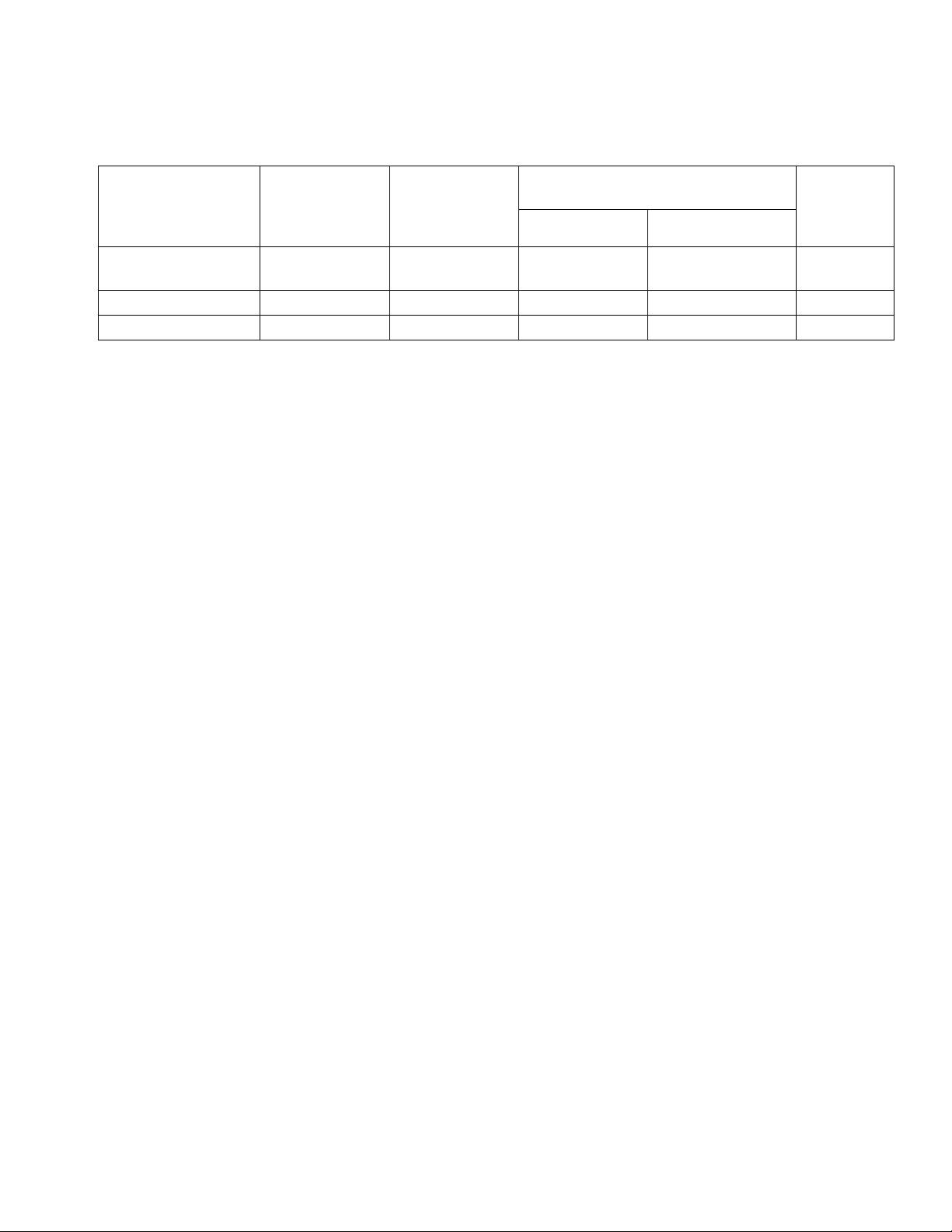
Models
Max Outlet
Fluid Working
Metering Valve
Model
Linear Resistive
Transducer (LRT)
Micrometer 2000 (14, 138) 100 (0.7, 7) 1200 (8, 83) 400 (2.8, 28) ✔
Motor Driven 2000 (14, 138) 100 (0.7, 7) 1200 (8, 83) 400 (2.8, 28) ✔
* If a custom PD44 is ordered, it will not be CE approved unless otherwise noted.
Pressure
psi (MPa, bar)
2000 (14, 138) 100 (0.7, 7) 1200 (8, 83) 400 (2.8, 28) ✔
Max Air
Working
Pressure
psi (MPa, bar)
Max Inlet Working Pressure
psi (MPa, bar)
CE
Approved*Metal Sleeves Plastic Sleeves
3A0987K 3
Page 4

Product Configurator
Product Configurator
This system can be ordered with many different options as shown in the configurator below.
PD44 C-A-BCD-EFG- H - I -J -K-L-M-NO-P-Q-RS-T-U-V-W- X
Configurator Series Level
Base Unit
High Volume Rod Material, Size
Low Volume Rod Material, Size
High Volume Spool
Low Volume Spool
Outlet Nose
Mixer
Controls
Power Cord
High Volume Feed
High Volume Feed Hose
High Volume Feed Options
Low Volume Feed
Low Volume Feed Hose
Low Volume Feed Options
Vacuum Pump(s)
Bench Stand
Seal Lubricant
The following table applies to the PD44 configurations and indicates all of the options available for each letter shown
above.
Code A Part Base Unit
A 964000 Micrometer PD44
B 964001 Linear Resistive Transducer PD44
C 964002 Motor Driven PD44
Code B Part High Volume Rod Material
NOTE: See code CD for last two digits of part number
A 9641__ Hardened Steel
B 9642__ Stainless Steel, UHMW
C 9643__ Tungsten Carbide, UHMW
Code
CD Part High Volume Rod Size
NOTE: See code B for first four digits of part number
01 ____01 1.25 mm rod diameter
02 ____02 1.38 mm rod diameter
03 ____03 1.50 mm rod diameter
04 ____04 1.63 mm rod diameter
05 ____05 1.75 mm rod diameter
06 ____06 2.00 mm rod diameter
07 ____07 2.13 mm rod diameter
08 ____08 2.25 mm rod diameter
09 ____09 2.38 mm rod diameter
10 ____10 2.50 mm rod diameter
11 ____11 2.63 mm rod diameter
12 ____12 2.75 mm rod diameter
13 ____13 3.00 mm rod diameter
14 ____14 3.13 mm rod diameter
15 ____15 3.25 mm rod diameter
16 ____16 3.38 mm rod diameter
17 ____17 3.50 mm rod diameter
18 ____18 3.63 mm rod diameter
19 ____19 3.75 mm rod diameter
20 ____20 4.00 mm rod diameter
21 ____21 4.25 mm rod diameter
22 ____22 4.50 mm rod diameter
23 ____23 4.63 mm rod diameter
24 ____24 4.75 mm rod diameter
25 ____25 4.88 mm rod diameter
26 ____26 5.00 mm rod diameter
27 ____27 5.13 mm rod diameter
28 ____28 5.25 mm rod diameter
29 ____29 5.50 mm rod diameter
30 ____30 5.75 mm rod diameter
31 ____31 6.00 mm rod diameter
32 ____32 6.13 mm rod diameter
33 ____33 6.25 mm rod diameter
34 ____34 6.38 mm rod diameter
35 ____35 6.50 mm rod diameter
36 ____36 6.63 mm rod diameter
37 ____37 6.75 mm rod diameter
38 ____38 7.00 mm rod diameter
39 ____39 7.25 mm rod diameter
40 ____40 7.50 mm rod diameter
41 ____41 7.63 mm rod diameter
42 ____42 7.75 mm rod diameter
43 ____43 7.88 mm rod diameter
44 ____44 8.00 mm rod diameter
Code E Part Low Volume Rod Material
NOTE: See code FG for last two digits of part number
A 9641__ Hardened Steel
B 9642__ Stainless Steel, UHMW
C 9643__ Tungsten Carbide, UHMW
4 3A0987K
Page 5
Product Configurator
Code FG Part Low Volume Rod Size
NOTE: See code E for first four digits of part number
01 ____01 1.25 mm rod diameter
02 ____02 1.38 mm rod diameter
03 ____03 1.50 mm rod diameter
04 ____04 1.63 mm rod diameter
05 ____05 1.75 mm rod diameter
06 ____06 2.00 mm rod diameter
07 ____07 2.13 mm rod diameter
08 ____08 2.25 mm rod diameter
09 ____09 2.38 mm rod diameter
10 ____10 2.50 mm rod diameter
11 ____11 2.63 mm rod diameter
12 ____12 2.75 mm rod diameter
13 ____13 3.00 mm rod diameter
14 ____14 3.13 mm rod diameter
15 ____15 3.25 mm rod diameter
16 ____16 3.38 mm rod diameter
17 ____17 3.50 mm rod diameter
18 ____18 3.63 mm rod diameter
19 ____19 3.75 mm rod diameter
20 ____20 4.00 mm rod diameter
21 ____21 4.25 mm rod diameter
22 ____22 4.50 mm rod diameter
23 ____23 4.63 mm rod diameter
24 ____24 4.75 mm rod diameter
25 ____25 4.88 mm rod diameter
26 ____26 5.00 mm rod diameter
27 ____27 5.13 mm rod diameter
28 ____28 5.25 mm rod diameter
29 ____29 5.50 mm rod diameter
30 ____30 5.75 mm rod diameter
31 ____31 6.00 mm rod diameter
32 ____32 6.13 mm rod diameter
33 ____33 6.25 mm rod diameter
34 ____34 6.38 mm rod diameter
35 ____35 6.50 mm rod diameter
36 ____36 6.63 mm rod diameter
37 ____37 6.75 mm rod diameter
38 ____38 7.00 mm rod diameter
39 ____39 7.25 mm rod diameter
40 ____40 7.50 mm rod diameter
41 ____41 7.63 mm rod diameter
42 ____42 7.75 mm rod diameter
43 ____43 7.88 mm rod diameter
44 ____44 8.00 mm rod diameter
Code H Part High Volume Spool
1 964003 High viscosity, HS
2 964004 High viscosity, Stainless Steel/UHMWPE
3 964005 High viscosity, TC/UHMWPE
4 964006 Low viscosity, Stainless Steel
Code I Part Low Volume Spool
1 964011 High viscosity, HS
2 964012 High viscosity, Stainless Steel/UHMWPE
3 964013 High viscosity, TC/UHMWPE
4 964014 Low viscosity, Stainless Steel
Code J Par t Outlet Nose
1 964020 Luer lock, equal ports, no check valves
2 964021 Luer lock, equal ports, dual check valves
3 964022 Equal ports, 7/8-9, no check valves
4 964023 Large and small ports, 7/8-9, no check
valves
5 964024 Large and small ports, 7/8-9, single
check valve
6 964025 Dual small ports, 7/8-9, no check valves
7 964026 Dual small ports, 7/8-9 dual check valves
Code K Part Mixer
1 964027 1/8-24 Luer Lock inlet and outlet, 0.5 cc
2 964028 3/16-32 bell mouth inlet, luer lock outlet,
2.0 cc
3 964029 1/4-24 bell mouth inlet, luer lock outlet,
4.0 cc
4 964030 1/4-32 bell mouth inlet, luer lock outlet,
5.5 cc
5 964031 1/4-48 bell mouth inlet, luer lock outlet,
8.0 cc
6 964032 3/16-32 bell mouth inlet, tapered outlet,
1.5 cc
7 964033 1/4-24 bell mouth inlet, tapered outlet,
3.5 cc
8 964034 3/16-24 bell mouth inlet, tapered outlet,
1.0 cc
3A0987K 5
Page 6

Product Configurator
Code L Part Controls
1 964035 Pneumatic, micrometer, wire harness
only
2 964036 Pneumatic, micrometer, HMI controls, low
level
3 964037 Pneumatic, micrometer, HMI controls, low
level, I/O package
4 964038 Pneumatic, micrometer, HMI controls, low
level, high level
5 964039 Pneumatic, micrometer, HMI controls, low
level, high level, I/O package
6 964040 Pneumatic, linear resistive transducer,
wire harness only
7 964041 Pneumatic, linear resistive transducer,
HMI controls, low level
8 964042 Pneumatic, linear resistive transducer,
HMI controls, low level, I/O package
9 964043 Pneumatic, linear resistive transducer,
HMI controls, low level, high level
A 964044 Pneumatic, linear resistive transducer,
HMI controls, low level, high level, I/O
package
B 964045 Motor driven, I/O, wire harness only
C 964046 Stepper motor, HMI control, low level,
high level, I/O package
Code M Part Power Cord
1 121055 120 VAC, North American cord set
2 121054 250 VAC, 1 phase, no plug
3 121056 10 amp, 250 volt, continental Europe
4 121057 10 amp, 250 volt, United Kingdom and
Ireland
5 121058 10 amp, 250 volt, Israel
6 124864 10 amp, 250 volt, Australia
7 124861 10 amp, 250 volt, Italy
8 124863 10 amp, 250 volt, Switzerland
9 124862 10 amp, 250 volt, Denmark
A 121060 10 amp, 250 volt, India
N -- None
Code
NO Part High Volume Feed
01 964050 20 oz cartridge feed with mounting post
02 964051
03 964052
04 964053 5 gallon pail cover diaphragm pump and
05 964054
06 964055
07 964056 5 gallon single post Ram with 11:1 pump,
08 964057 5 gallon single post Ram with 11:1 pump,
09 964058
10 964059
11 964060 5 gallon tank, support, diaphragm pump,
12 964061 5 gallon tank, support, diaphragm pump,
13 964062 5 gallon tank, support, diaphragm pump,
14 964063 5 gallon tank, support, diaphragm pump,
15 964064 5 gallon tank, support and 5:1 pump, mild
16 964065 5 gallon tank, support, 5:1 pump, agitator,
17 964066
18 964067 5 gallon tank, support, 5:1 pump, stain-
1 gallon pail Ram and transfer pump
5 gallon pail cover with diaphragm pump
agitator
5 gallon pail cover and 5:1 transfer pump
5 gallon pail cover, 1:1 pump with dip
tube for moisture sensitive materials
mild steel
stainless steel
5 gallon tank, support and diaphragm
pump, mild steel
5 gallon tank, support, diaphragm pump
and agitator, mild steel
agitator and vacuum fill, mild steel
stainless steel
agitator, stainless steel
agitator, vacuum fill, stainless steel
steel
mild steel
5 gallon tank, support, 5:1 pump, agitator,
vacuum fill, mild steel
less steel
6 3A0987K
Page 7
Product Configurator
19 964068
20 964069
21 964070 10 gallon tank, support, diaphragm
22 964071 10 gallon tank, support, diaphragm
23 964072 10 gallon tank, support, diaphragm
24 964073 10 gallon tank, support, diaphragm
25 964074 10 gallon tank, support, diaphragm
26 964075
27 964076
28 964077 10 gallon tank, support, 5:1 pump, agita-
29 964078 10 gallon tank, support, 5:1 pump, agita-
30 964079 10 gallon tank, support, 5:1 pump, stain-
31 964080 10 gallon, tank, support, 4:1 pump, agita-
32 964081 10 gallon tank, support, 5:1 pump, agita-
NN -- None
Code P Part High Volume Feed Hose
1 964082 1/2 in. x 8 ft PTFE and stainless steel
3 964084 1/2 in. x 10 ft PTFE and stainless steel
5 964086 1/2 in. x 15 ft PTFE and stainless steel
N -- None
Code Q Part High Volume Feed
A 964088 Dessicant dryers for tank lids
B 964089 Nitrogen harness assembly for tank lids
C 964090 Low level sensor 11:1 Ram only
N -- None
5 gallon tank, support, 5:1 pump, agitator,
stainless steel
5 gallon tank, support, 5:1 pump, agitator,
vacuum fill, stainless steel
pump, mild steel
pump, agitator, mild steel
pump, agitator, vacuum fill, mild steel
pump, stainless steel
pump, agitator, stainless steel
10 gallon tank, support, diaphragm
pump, agitator, vacuum fill, stainless steel
10 gallon tank, support, 5:1 pump, mild
steel
tor, mild steel
tor, vacuum fill, mild steel
less steel
tor, stainless steel
tor, vacuum fill, stainless steel
hose, stainless steel fittings
hose, stainless steel fittings
hose, stainless steel fittings
Code RS Par t Low Volume Feed
01 964050 20 oz cartridge feed with mounting post
02 964051
03 964052
04 964053
05 964054 5 gallon pail cover and 5:1 transfer pump
06 964055 5 gallon pail cover, 1:1 pump with dip
07 964056
08 964057
09 964058 5 gallon tank, support and diaphragm
10 964059 5 gallon tank, support, diaphragm pump
11 964060 5 gallon tank, support, diaphragm pump,
12 964061 5 gallon tank, support, diaphragm pump,
13 964062 5 gallon tank, support, diaphragm pump,
14 964063
15 964064 5 gallon tank, support and 5:1 pump, mild
16 964065 5 gallon tank, support, 5:1 pump, agitator,
17 964066 5 gallon tank, support, 5:1 pump, agitator,
18 964067 5 gallon tank, support, 5:1 pump, stain-
1 gallon pail Ram and transfer pump
5 gallon pail cover with diaphragm pump
5 gallon pail cover diaphragm pump and
agitator
tube for moisture sensitive materials
5 gallon single post Ram with 11:1 pump,
mild steel
5 gallon single post Ram with 11:1 pump,
stainless steel
pump, mild steel
and agitator, mild steel
agitator and vacuum fill, mild steel
stainless steel
agitator, stainless steel
5 gallon tank, support, diaphragm pump,
agitator, vacuum fill, stainless steel
steel
mild steel
vacuum fill, mild steel
less steel
3A0987K 7
Page 8

Product Configurator
19 964068
20 964069
21 964070 10 gallon tank, support, diaphragm
22 964071 10 gallon tank, support, diaphragm
23 964072 10 gallon tank, support, diaphragm
24 964073 10 gallon tank, support, diaphragm
25 964074 10 gallon tank, support, diaphragm
26 964075
27 964076
28 964077 10 gallon tank, support, 5:1 pump, agita-
29 964078 10 gallon tank, support, 5:1 pump, agita-
30 964079 10 gallon tank, support, 5:1 pump, stain-
31 964080 10 gallon, tank, support, 4:1 pump, agita-
32 964081 10 gallon tank, support, 5:1 pump, agita-
NN -- None
Code T Part Low Volume Feed Hose
1 964082 1/2 in. x 8 ft PTFE and stainless steel
3 964084 1/2 in. x 10 ft PTFE and stainless steel
5 964086 1/2 in. x 15 ft PTFE and stainless steel
7 -- None
Code U Part Low Volume Feed
A 964088 Dessicant dryers for tank lids
B 964089 Nitrogen harness assembly for tank lids
C 964090 Low level sensor 11:1 Ram only
N -- None
Code V Part Vacuum Pump(s)
1 964091 1-115V, 1 phase, 6.9 cfm, inlet and outlet
2 964092 1-115V, 1 phase, 6.9 cfm, inlet and outlet
3 964093 1-230V, 1 phase, 6.9 cfm, inlet and outlet
4 964094 1-230V, 1 phase, 6.9 cfm, inlet and outlet
N -- None
5 gallon tank, support, 5:11 pump, agita-
tor, stainless steel
5 gallon tank, support, 5:1 pump, agitator,
vacuum fill, stainless steel
pump, mild steel
pump, agitator, mild steel
pump, agitator, vacuum fill, mild steel
pump, stainless steel
pump, agitator, stainless steel
10 gallon tank, support, diaphragm
pump, agitator, vacuum fill, stainless steel
10 gallon tank, support, 5:1 pump, mild
steel
tor, mild steel
tor, vacuum fill, mild steel
less steel
tor, stainless steel
tor, vacuum fill, stainless steel
hose, stainless steel fittings
hose, stainless steel fittings
hose, stainless steel fittings
filter, 1 in. hose to single tank
filter, 1 in. hose to two tanks
filter, 1 in. hose to single tank
filter, 1 in. hose to two tanks
Code W Part Bench Stand
A 964095 Adjustable height bench stand
N -- None
Code X Part Seal Lubricant
T 206994
Fluid, TSL™, 8 ounce bottle
8 3A0987K
Page 9
Accessories
Mixer Kits with Shroud
Part Description
964034 Mixer, Kit, 3/16 in. (4.8mm) x 24, 10
taper tip mixers with shroud
964032 Mixer, Kit, 3/16 in. (4.8mm) x 32, 10
taper tip mixers with shroud
964028 Mixer, Kit, 3/16 in. (4.8mm) x 32, 10
Luer Lock tip mixers with shroud/sleeve
964033 Mixer, Kit, 1/4 in. (6.5mm) x 24, 10
taper tip mixers with shroud
964029 Mixer, Kit, 1/4 in. (6.5mm) x 24, 10 Luer
Lock tip mixers with shroud/sleeve
964030 Mixer, Kit, 1/4 in. (6.5mm) x 32, 10 Luer
Lock tip mixers with shroud/sleeve
964031 Mixer, Kit, 1/4 in. (6.5mm) x 48, 10 Luer
Lock tip mixers with shroud/sleeve
Accessories
Mixer Packs
Part Description
964027 Mixer, 1/8 in. (3.2mm) x 24 Luer Lock
inlet/tip, 10 Pack
16D962 Mixer, 1/8 in. (3.2mm) x 24 Luer Lock
inlet/tip, 50 Pack
16D963 Mixer, 1/8 in. (3.2mm) x 24 Luer Lock
inlet/tip, 250 Pack
16D978 Mixer, 3/16 in. (4.8mm) x 24 taper tip,
50 Pack
16D979 Mixer, 3/16 in. (4.8mm) x 24 taper tip,
250 Pack
LC0077 Mixer, 3/16 in. (4.8mm) x 32 taper tip,
50 Pack
LC0084 Mixer, 3/16 in. (4.8mm) x 32 taper tip,
250 Pack
LC0082 Mixer, 3/16 in. (4.8mm) x 32 Luer Lock
tip, 50 Pack
LC0090 Mixer, 3/16 in. (4.8mm) x 32 Luer Lock
tip, 250 Pack
LC0078 Mixer, 1/4 in. (6.5mm) x 24 taper tip
mixer, 50 Pack
LC0085 Mixer, 1/4 in. (6.5mm) x 24 taper tip
mixer, 250 Pack
LC0083 Mixer, 1/4 in. (6.5mm) x 24 Luer Lock
tip, 50 Pack
Part Description
LC0089 Mixer, 1/4 in. (6.5mm) x 24 Luer Lock
tip, 250 Pack
16D968 Mixer, 1/4 in. (6.5mm) x 32 Luer Lock
tip, 50 Pack
16D969 Mixer, 1/4 in. (6.5mm) x 32 Luer Lock
tip, 250 Pack
16D970 Mixer, 1/4 in. (6.5mm) x 48 Luer Lock
tip, 50 Pack
16D973 Mixer, 1/4 in. (6.5mm) x 48 Luer Lock
tip, 250 Pack
3A0987K 9
Page 10

Accessories
O-Rings and Seals
For o-ring and seal locations, see the following sections:
• Metering Rod and Spool Valve Cross Section,
beginning on page 18
• High Viscosity Spool Valve Components,
page 20
• Low Viscosity Spool Valve Components, page 22
Part Description
24E247 Kit, O-ring, chemical resistant, PD44
24E248 Kit, Seal, Spool, H.V., PD44
24E249 Kit, Seal, Spool, L.V., PD44
16B265 Seal, Posipack, 1.25, ZAP
16B266 Seal, Posipack, 1.38, ZAP
16B267 Seal, Posipack, 1.50, ZAP
16B268 Seal, Posipack, 1.63, ZAP
16B269 Seal, Posipack, 1.75, ZAP
16B270 Seal, Posipack, 2.00, ZAP
16B271 Seal, Posipack, 2.13, ZAP
16B272 Seal, Posipack, 2.25, ZAP
16B273 Seal, Posipack, 2.38, ZAP
16B274 Seal, Posipack, 2.50, ZAP
16B275 Seal, Posipack, 2.63, ZAP
16B276 Seal, Posipack, 2.75, ZAP
16B277 Seal, Posipack, 3.00, ZAP
16B278 Seal, Posipack, 3.13, ZAP
16B279 Seal, Posipack, 3.25, ZAP
16B280 Seal, Posipack, 3.38, ZAP
16B281 Seal, Posipack, 3.50, ZAP
16B282 Seal, Posipack, 3.63, ZAP
16B283 Seal, Posipack, 3.75, ZAP
16B284 Seal, Posipack, 4.00, ZAP
16B285 Seal, Posipack, 4.25, ZAP
16B286 Seal, Posipack, 4.50, ZAP
16B287 Seal, Posipack, 4.63, ZAP
16B288 Seal, Posipack, 4.75, ZAP
16B289 Seal, Posipack, 4.88, ZAP
16B290 Seal, Posipack, 5.00, ZAP
16B291 Seal, Posipack, 5.13, ZAP
16B292 Seal, Posipack, 5.25, ZAP
16B293 Seal, Posipack, 5.50, ZAP
16B294 Seal, Posipack, 5.75, ZAP
16B295 Seal, Posipack, 6.00, ZAP
Part Description
16B296 Seal, Posipack, 6.13, ZAP
16B297 Seal, Posipack, 6.25, ZAP
16B298 Seal, Posipack, 6.38, ZAP
16B299 Seal, Posipack, 6.50, ZAP
16B300 Seal, Posipack, 6.63, ZAP
16B301 Seal, Posipack, 6.75, ZAP
16B302 Seal, Posipack, 7.00, ZAP
16B303 Seal, Posipack, 7.25, ZAP
16B304 Seal, Posipack, 7.50, ZAP
16B305 Seal, Posipack, 7.63, ZAP
16B306 Seal, Posipack, 7.75, ZAP
16B307 Seal, Posipack, 7.88, ZAP
16B450 Seal, Posipack, 8.00, ZAP
10 3A0987K
Page 11

Needles
Part Description
E4000025-50 Needle, Luer Lock, Sampler Package
(10 each 14 ga x 1/2 in., 16 ga x
1/2 in., 18 ga x 1/2 in., 20 ga x 1/2 in.,
22 ga x 1/2 in.)
E4000001-50 Needle, Luer Lock, 14 Gauge x 1/2 in.,
50 Pack
E4000004-50 Needle, Luer Lock, 15 Gauge x 1/2 in.,
50 Pack
E4000005-50 Needle, Luer Lock, 16 Gauge x 1 in.,
50 Pack
E4000006-50 Needle, Luer Lock, 18 Gauge x 1 in.,
50 Pack
E4000011-50 Needle, Luer Lock, 22 Gauge x 1/2 in.,
50 Pack
E4000014-50 Needle, Luer Lock, 14 Gauge x 1 in.,
50 Pack
E4000024-50 Needle, Luer Lock, 23 Gauge x 1/2 in.,
50 Pack
E4000088-50 Needle, Luer Lock, 16 Gauge x 1/2 in.,
50 Pack
Accessories
3A0987K 11
Page 12
Parts
Parts
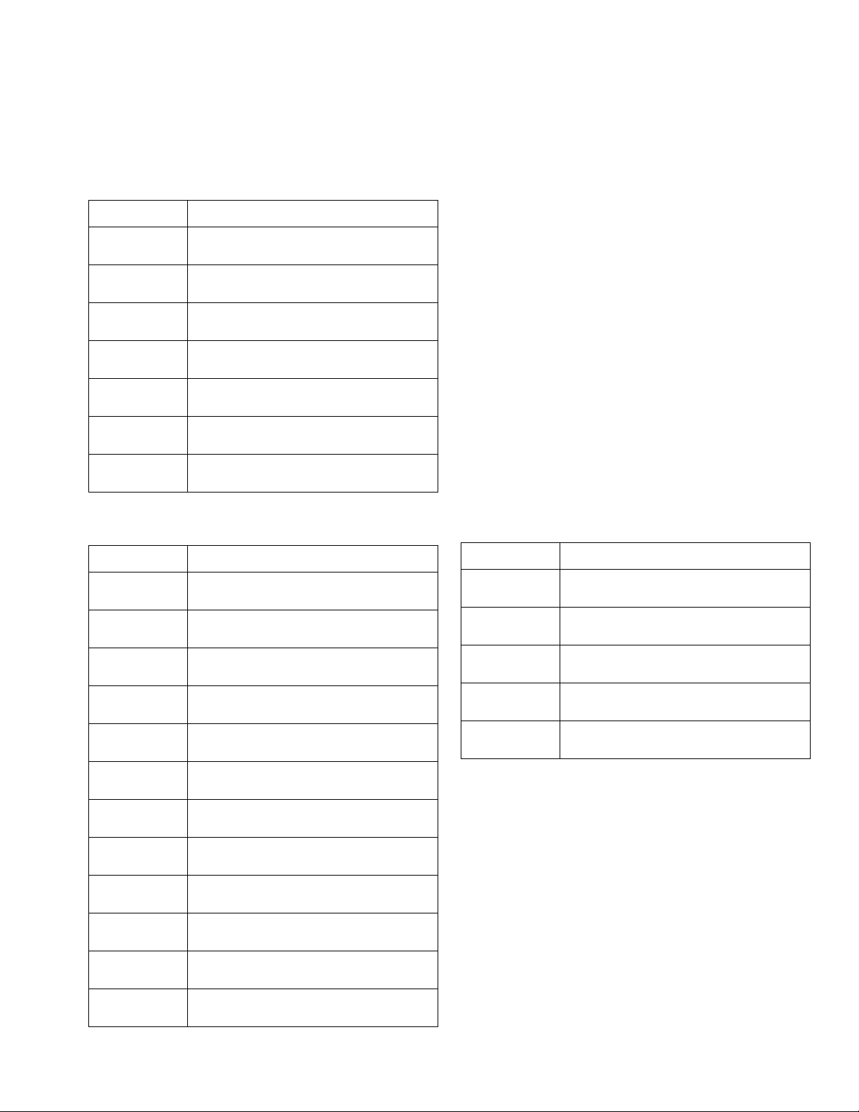
Micrometer Drive, 02/2980-1/25
1
117
1 3
124
122
121
115
111
110
105
124
123
125
128
129
2
512340 69078
130
127
04321 87 210965 9873564
126
112
1
119
118
116
1
1
131
131
132 132
114
113
1 3
3
111
112
116
4
6
106
104
5
7
120
107
4
103
102
45
108
6
109
101
1
Use Krytox 203gpl on all air cylinder seals
and surfaces.
2
Align micrometer number line with needle
valve port center.
3
Note direction of seals on air cylinder piston
and on piston rod seal.
4
Mount piston rod (116) to connecting
block (107). Use removable thread locker
Loctite #242 blue or equivalent.
12 3A0987K
5
Torque fastener to 67-70 in-lb
(7.6-7.9 N•m).
6
Install spring plunger (106) and retaining
plate (108) onto connecting block.
7
Torque fastener to 4-8 in-lb
(0.45-0.90 N•m).
Page 13

Ref Part Description Qty
101 01/2984-2/97 BLOCK, retainer, oil cup 1
102 01/2983/97 PLATE, tie, front, 2 in. 1
103 01/2982-1/97 PLATE, plate, tie, back 1
104 96/0305/99 SCREW, socket head cap, 10-24 x 2.00,
mild steel
105 01/2706-2.0/99 ROD, rod, guide, 1.5b x 2.0s 2
106 84/0263/11 PLUNGER, 10-32 1
107 01/2980/97 BLOCK 1
108 01/2981/99 RETAINER, rod, metering 1
109 96/0458/99 SCREW, fhsc, 10-32 x 0.50, mild steel 1
110 96/2955/98 SCREW, socket head cap, 10-24 x 0.18,
stainless steel
111 01/2985/97 BLOCK, air cylinder 1
112* 95/0504/01 O-RING, buna, 028, 70a 2
113* 95/0849/11 SEAL, posipak, 3/8 ID x 5/8 OD 1
114 01/2704/98 WASHER, air cylinder 1
115 96/0425/99 RING, 0.625, mild steel 1
116 01/2979/97 ROD, air cylinder 1
117* 95/0601/01 SEAL, u-cup, 1-3/16 ID x 1-1/2 OD 2
118 01/2702/97 PISTON, air cylinder, rod, 1.5b x 2.0s 1
119 01/2701-2.0/97 TUBE, air cylinder, aluminum 1
120 96/0608/99 SCREW, shs, 6-32 x 0.31, cup point,
mild steel
121* 95/0900/00 O-RING, fluoroelastomer, 009, 75a 1
122† 01/2969/97 CAP, top, air cylinder, rod 1
123† --- TOOL, micrometer, 0-2 in. 1
124 96/0098-45/99 SCREW, shc, 10-24 x 4.50, mild steel 4
125† 96/0523/99 SCREW, shs, 1/4-20 x 0.38, cone point,
mild steel
126 94/0525/96 FITTING, nipple, hex, 1/8 npt, brass 1
127 94/0767/96 COUPLING, hex, 1/8 npt, brass 1
128 123541 VALVE, needle, 1/8 npt x 1/4 t,
press-to-fit
129 123540 BUTTON, snap-on, 1/4 tube, red 1
130 123539 BUTTON, snap-on, 1/4 tube, blue 1
131 01/2995/11 GUARD, guard, side 2
132 96/0271/99 FASTENER, bhcs, 8-32 x 0.31, mild
steel
Parts
4
8
2
2
2
6
* Parts included in Kit 95/2980-1/25 (purchase separately).
† Parts included in assembly 24K620 (purchase sepa-
rately).
--- Parts not available for individual sale.
3A0987K 13
Page 14
Parts
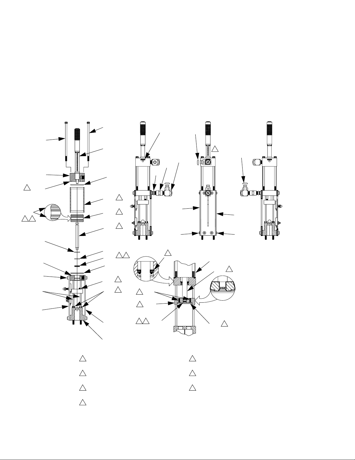
Linear Resistive Transducer Drive
212
211
206
202
PG-7
LOOKING FROM SOLDER SIDE
3 WHT
2 RED
MALE
1 BLK
203
PG-7
205
M
213
207
202
204
1
3
2
LEFT SIDE VIEW
208
222
214
215
216
219
220
217
218
219
220
FRONT VIEW
4
221
RIGHT SIDE VIEW
220
210
21
209
3
201
1
Use removable thread locker Loctite #242 blue or equal on fastener (210)
and cylinder (213).
2
Torque fastener to 67-70 in-lb (7.6-7.9 N•m).
3
Install spring plunger (207) and retaining plate (209) onto connecting
block.
4
Torque fastener to 4-8 in-lb (0.45-0.90 N•m).
14 3A0987K
Page 15

Ref Part Description Qty
201 01/2984-2/97 BLOCK, retainer, oil cup 1
202 01/2983/97 PLATE, tie, front, 2 in. 2
203 81/0360-3M/11 CONNECTOR, plug, male, 3-pin, RTD 1
204 61/0086/11 JACKET, shrink, 1/8, black, semi-rigid 0.5
205 96/0305/99 SCREW, shc, 10-24 x 2.00, mild steel 4
206 01/2706-2.0/99 ROD, rod, guide, 1.5b x 2.0s 2
207 84/0263/11 PLUNGER, 10-32 1
208 01/2980/97 BLOCK 1
209 01/2981/99 RETAINER, rod, metering 1
210 96/0458/99 SCREW, fhsc, 10-32 x 0.50, mild steel 1
211 96/2955/98 SCREW, shc, shdr, 0.25, 10-24 x 0.18,
stainless steel
212 01/2985-1/97 BLOCK, air cylinder, lvdt 1
213 83/0070-2PD/11 CYLINDER, 1.5b x 2.0s, special tip 1
214 94/0499/96 ADAPTER, hex, 1/4 npt x 1/8 npt, male x
male, brass
215 94/0767/96 COUPLING, hex, 1/8 npt, brass 1
216 123541 VALVE, needle, 1/8 npt x 1/4 t, press-to-fit 2
217 123540 BUTTON, snap-on, 1/4 tube, red 1
218 123539 BUTTON, snap-on, 1/4 tube, blue 1
219 01/2995/11 GUARD, guard, side 2
220 96/0271/99 FASTENER, bhcs, 8-32 x 0.31, mild steel 6
221 96/0608/99 SCREW, shs, 6-32x0.31, cup pt, mild steel 2
222 94/0598/96 BUSHING, 1/4npt x 1/8npt, brass 1
Parts
8
1
3A0987K 15
Page 16
Parts
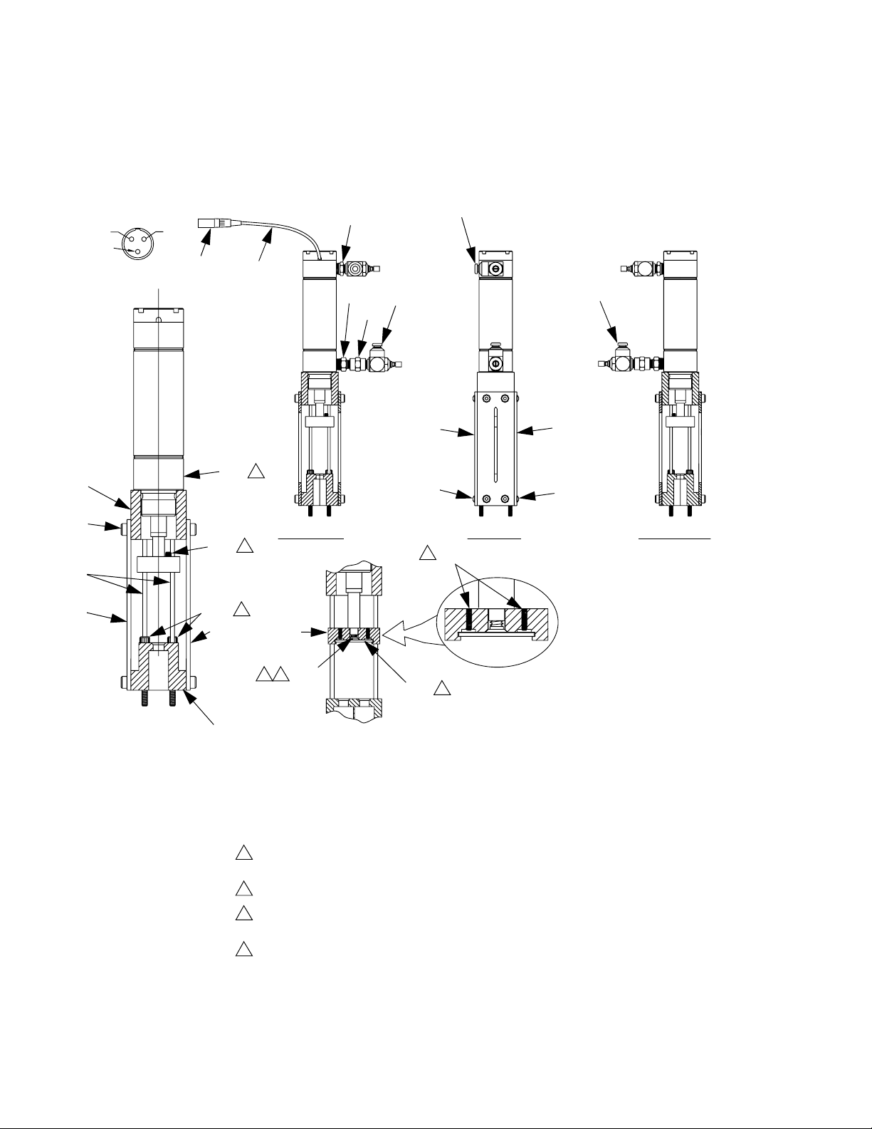
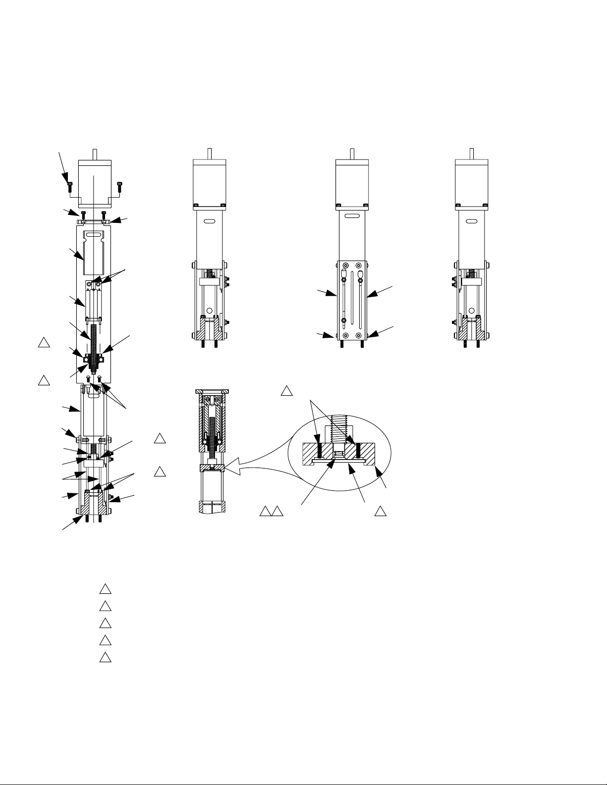
Stepper Motor Drive
317
322
1
1
311
310
323
327
305
302
320
318
316
314
313
321
319
315
312
306
304
303
325
312
5
324
325
312
4
3
307
32
309 308
4
301
1
Press bearing (314) onto lead screw drive nut (315). Secure with retaining ring (313).
2
Use removable thread locker Loctite #242 blue or equal on fastener (309).
3
Torque fastener to 67-70 in-lb (7.6-7.9 N•m).
4
Install spring plunger (306) and retaining plate (308) onto connecting block.
5
Torque fastener to 4-8 in-lb (0.45-0.90 N•m).
16 3A0987K
Page 17

Ref Part Description Qty
301 01/2984-2/97 BLOCK, retainer, oil cup, 1.5b 1
302 01/2983/97 PLATE, tie, front, 2 in. 1
303 01/2982-1/97 PLATE, plate, tie, back 1
304 96/0305/99 SCREW, shc, 10-24 x 2.00, mild steel 4
305 01/2706-2.0/99 ROD, rod, guide, 1.5b x 2.0s 2
306 84/0263/11 PLUNGER, 10-32 1
307 01/2980/97 BLOCK 1
308 01/2981/99 RETAINER, rod, metering, pd3 1
309 96/0458/99 SCREW, fhsc, 10-32 x 0.50, mild steel 1
310 96/2955/98 SCREW, shc, 0.25, 10-24 x 0.18,
stainless steel
311 01/2990/97 HOUSING, lead screw 1
312 96/0271/99 FASTENER, bhcs, 8-32 x 0.31, mild
steel
313 96/0209/99 RING, 0.625, mild steel 1
314 84/0129/11 BALL, 0.62ID x 1.375 OD 1
315 01/2993/25 NUT, lead screw, drive 1
316 01/2994/25 SCREW, lead screw, drive 1
317 96/0323/99 SCREW, shc, 10-32 x 0.50, mild steel 4
318 01/2991-1/97 COUPLER, lead screw, 1/4 1
319 96/0363/99 SCREW, shc, 6-32 x 0.38, mild steel 2
320 01/2992/97 RETAINER, bearing, leadscrew 1
321 01/2890/97 PLATE 1
322 96/0187/98 SCREW, shc, 8-32 x 0.38, stainless
steel
323 01/2993-S/89 SPACER, drive nut 1
324 96/0608/99 SCREW, shs, 6-32 x 0.31, cup point,
mild steel
325 01/2995/11 GUARD, guard, side 2
327 B3000061 SCREW, shs, 6-32 x 0.25, nylon point,
stainless steel
Parts
8
8
4
2
1
3A0987K 17
Page 18

Parts
Metering Rod and Spool Valve Cross Section
Set Screw
“A” Side
402a
402b
†
404a
402c
†
404b
◆
404c
High Viscosity Shown
Connecting Plate
Slide Plate
Front
404d
“A” Side
† O-ring
◆ PTFE Gasket
NOTE: Other parts of valve that are not included in this assembly are shown
for reference only.
NOTE: See the rebuild procedure in the PD44 Metering Valves and Feed Systems Operation and Maintenance manual. See Related Manuals on page 2.
18 3A0987K
Page 19

Rod Assembly Kits
Description
KIT, rod, 1.25 964101
KIT, rod, 1.38 964102
KIT, rod, 1.50 964103
KIT, rod, 1.63 964104
KIT, rod, 1.75 964105
KIT, rod, 2.00 964106
KIT, rod, 2.13 964107
KIT, rod, 2.25 964108
KIT, rod, 2.38 964109
KIT, rod, 2.50 964110
KIT, rod, 2.63 964111
KIT, rod, 2.75 964112
KIT, rod, 3.00 964113
KIT, rod, 3.13 964114
KIT, rod, 3.25 964115
KIT, rod, 3.38 964116
KIT, rod, 3.50 964117
KIT, rod, 3.63 964118
KIT, rod, 3.75 964119
KIT, rod, 4.00 964120
KIT, rod, 4.25 964121
KIT, rod, 4.50 964122
KIT, rod, 4.63 964123
KIT, rod, 4.75 964124
KIT, rod, 4.88 964125
KIT, rod, 5.00 964126
KIT, rod, 5.13 964127
KIT, rod, 5.25 964128
KIT, rod, 5.50 964129
KIT, rod, 5.75 964130
KIT, rod, 6.00 964131
KIT, rod, 6.13 964132
KIT, rod, 6.25 964133
KIT, rod, 6.38 964134
KIT, rod, 6.50 964135
KIT, rod, 6.63 964136
KIT, rod, 6.75 964137
KIT, rod, 7.00 964138
KIT, rod, 7.25 964139
KIT, rod, 7.50 964140
KIT, rod, 7.63 964141
KIT, rod, 7.75 964142
KIT, rod, 7.88 964143
KIT, rod, 8.00 964144
402 † 404 ◆
Hardened Steel
Rod Assembly Kit
Reference
Stainless Steel
Rod Assembly Kit
964201 964301
964202 964302
964203 964303
964204 964304
964205 964305
964206 964306
964207 964307
964208 964308
964209 964309
964210 964310
964211 964311
964212 964312
964213 964313
964214 964314
964215 964315
964216 964316
964217 964317
964218 964318
964219 964319
964220 964320
964221 964321
964222 964322
964223 964323
964224 964324
964225 964325
964226 964326
964227 964327
964228 964328
964229 964329
964230 964330
964231 964331
964232 964332
964233 964333
964234 964334
964235 964335
964236 964336
964237 964337
964238 964338
964239 964339
964240 964340
964241 964341
964242 964342
964243 964343
964244 964344
Parts
Tungsten Carbide
Rod Assembly Kit Description Part
KIT, o-ring 24E247
† Seals are available separately. See O-Rings and Seals section on page 10.
◆ One kit is required for each side of the valve A and B.
3A0987K 19
Page 20

Parts
High Viscosity Spool Valve Components
A
MODEL NUMBER
PD44C-ABCDEFGHIJKLMNOPQRSTUVWX
MAX FLUID WPR
XXXX Mpa XXXX bar XXXX PSI
MAX AIR WPR
0.7 Mpa 7 bar 100 PSI
SERIES
SERIAL
UA1234 NF09A
A
514
505
505
510
502
514
510
502
BA
506
502
503 507
502507 503 501
NOTE: See the rebuild procedure in the PD44 Metering Valves and Feed Systems
Operation and Maintenance manual. See Related Manuals on page 2.
20 3A0987K
Page 21

Quantity †
Ref Part Description
Spool
Valve,
A Side,
HS
Spool
Valve,
A Side,
SS
Spool
Valve,
A Side,
TC
Spool
Valve,
B Side,
HS
Spool
Valve,
B Side,
SS
Spool
Valve,
B Side,
TC
501★ RING, quad 4 4 4 4 4 4
502★ O-RING 4 4 4 4 4 4
503★ O-RING 6 6 6 6 6 6
505★ SEAL 2 2 2 2 2 2
506◆ U50205 VALVE, spool, HS, A Side 1
24E565 VALVE, spool, SS, A Side 1
24E579 VALVE, spool, TC, A Side 1
U50206 VALVE, spool, HS, B Side 1
24E566 VALVE, spool, SS, B Side 1
24E567 VALVE, spool, TC, B Side 1
507 01/2975-4/98 WASHER, seal, high viscosity 2 2 2 2 2 2
510 01/2974-5/70 CARTRIDGE, high viscosity, 1.5b 2 2 2 2 2 2
514 01/2989/98 RETAINER, seal, spool, high viscosity 2 2 2 2 2 2
Parts
† Quantities listed are for one side of the valve.
★ O-rings and seals are contained in kit 24E248. 1 kit
is required for each side of the valve.
◆ HS = hardened steel, SS = stainless steel,
TC = Tungsten Carbide/UHMW.
Spools are handed: A-Side, B-Side.
3A0987K 21
Page 22

Parts
Low Viscosity Spool Valve Components
A
MODEL NUMBER
PD44C-ABCDEFGHIJKLMNOPQRSTUVWX
MAX FLUID WPR
XXXX Mpa XXXX bar XXXX PSI
MAX AIR WPR
0.7 Mpa 7 bar 100 PSI
SERIES
SERIAL
UA1234 NF09A
AB
A
609611608
610
611
609
603
606
603
606
608
612
605
601602
602
603
610
611
NOTE: See the rebuild procedure in the PD44 Metering Valves and Feed Systems
Operation and Maintenance manual. See Related Manuals on page 2.
611
22 3A0987K
Page 23

Quantity †
Ref Part Description
Spool Valve,
Low Viscosity,
A Side
Spool Valve,
Low Viscosity,
B Side
601★ RING, quad 4 4
602★ O-RING 2 2
603★ O-RING 4 4
605★ SEAL 6 6
606★ O-RING 2 2
608 01/2960/98 SPOOL, low viscosity 1 1
609◆ 01/2961/98 SLEEVE, low viscosity, A side,
1
stainless steel, quad
01/2962/98 SLEEVE, low viscosity, B side,
stainless steel, quad
610 01/2975-3/98 WASHER, seal, low viscosity 2 2
611 01/2977/70 CAP, end, seal, low viscosity 2 2
612 01/2963/98 SPACER, seal, low viscosity 3 3
Parts
1
† Quantities listed are for one side of the valve.
★ O-rings and seals are contained in kit 24E249. 1 kit
is required for each side of the valve.
◆ Sleeves are handed: A-Side, B-Side.
3A0987K 23
Page 24

Parts
Spool Air Piston Assembly
701
708
702
703
704
705
706
709
707
1
Apply thin coat of krytox 203GPL to inner diameter of
cylinder wall (704).
2
Use krytox 203GPL on all o-ring and seal surfaces.
Ref Part Description Qty
701 123453 FITTING, 1/4 tube x 1/8 npt, male 1
702 16A565 CAP, end, air cylinder, spool 1
703 95/0504/01 O-RING, buna, 028, 70a 1
704 01/2973/97 CYLINDER, cylinder, air, spool, 1.5 1
705 01/2976/97 PISTON, air cylinder, spool, 1.5b 1
706 95/0601/01 SEAL, u-cup, 1-3/16 ID x 1-1/2 OD, nitrile 1
707 01/2971-1/97 BLOCK, seal, air cylinder, spool 1
708 96/0305/99 SCREW, shc, 10-24 x 2.00, mild steel 2
709 104702 SCREW, cap, socket head 1
24 3A0987K
Page 25

Material Inlet Blocks
Parts
2103
2102a
2102b
1
1
Torque fasteners to 67-70 in-lb (7.6-7.9 N•m).
Ref Part Description Qty
2102 02/2995-S/25 KIT, inlet, PD44, top, 1/4 NPT, LH, SS 1
.2102a 16A570 BLOCK, PD44, top inlet, 1/4 NPT, SS 1
.2102b 96/0097/99 SCREW, socket head, #10-24x1.25, MS 4
2103★ 24E247 KIT, o-ring, FX75, PD44 1
2104 02/2996-S/25 KIT, inlet, PD44, top, 1/4 NPT, RH, SS 1
.2104a 16A571 BLOCK, PD44, top inlet, 1/4 NPT, SS 1
.2104b 96/0097/99 SCREW, socket head, #10-24x1.25, MS 4
★ Kit includes additional o-rings. See Metering Rod and Spool Valve Cross Section beginning on page 18,
item 404.
2104b
2104a
2103
1
3A0987K 25
Page 26

Parts
1:1 Luer Nose
A
803
B
804
807 806
802
808
805
Ref Part Description Qty
802 01/2725/98 BLOCK, nose, body, 1.5b x 1:1 1
805 96/0125/99 SCREW, shc, 10-24 x 0.50, mild steel 2
806 94/3108/70 BALL, ball, 0.094 dia, acetal 2
807 96/0510/99 SCREW, shs, 6-32 x 0.13, flat point, mild
steel
808 94/0645/89 RING, lock, nylon 1
806
807
2
26 3A0987K
Page 27

Luer Lock Nose with Check Valves
Parts
906
907
903
907
904
905
902
912
909
A
B
907
908
908
908
904
905
911
910
Ref Part Description Qty
902 01/2734/98 BLOCK, 1.5b, 1:1, a/b 1
903 01/2728/98 PLATE, retaining, nose, 1.5b, 1:1,
1
stainless steel
904 94/3110/70 BALL, ball, 0.125 dia, acetal 2
905 97/0203/98 SPRING, compression, 0.120 OD x
2
0.3125l, 7.41l
906 96/0119/99 SCREW, fhsc, 6-32 x 0.50, mild steel 2
907★ O-RING 2
908★ O-RING 2
909 96/0307-1/99 SCREW, shc, 10-24 x 1.00, mild steel 2
910 94/3108/70 BALL, ball, 0.094 dia, acetal 2
911 96/0510/99 SCREW, shs, 6-32 x 0.13, flat point, mild
2
steel
912 94/0645/89 RING, lock, nylon 1
★ O-rings are available in kit 24E247. See Metering Rod and Spool Valve Cross Section beginning on page 18.
3A0987K 27
Page 28

Parts
Standard Nose with 7/8-9 Thread
A
1003
1002
7/8-9 Thread
1005
B
1007
1008
1006
Quantity
Ref Part Description
Large Port A,
Large Port B
Large Port A,
Small Port B
1002 01/2726/98 BLOCK, nose 1
01/2723/98 BLOCK, nose 1
1003★ O-RING 2 2
1005 96/0125/99 SCREW, shc, 10-24 x 0.50, mild steel 2 2
1006 60/0137/89 NUT, retaining, 3/16”, 1/4”, & 3/8” 1 1
1007 01/2828/87 NOZZLE, ratio check, PD, 1.5, plug 1 1
1008 01/2825-2/87 NOZZLE, ratio check, PD, 1.5B, H1/Low 1
01/2825/87 NOZZLE, ratio check, PD, 1.5B notes 1
★ O-rings are available in kit 24E247. See Metering
Rod and Spool Valve Cross Section beginning on
page 18.
28 3A0987K
Page 29

Nose with 7/8-9 Thread and Check Valves
A
B
1105
Parts
1107
Check Ball
Assembly Detail
1102
1106
1107
1103
1104
1109
7/8-9 Thread
1108
1111
1112
1110
Quantity
Ref Part Description
1102 01/2728/98 PLATE, retaining, nose, 1.5b, 1:1,
Small Ports,
Dual Check
1
Small Ports,
No Check
stainless steel
1103 94/3110/70 BALL, ball, 0.125 dia, acetal 2
1104 97/0203/98 SPRING, compression, 0.120 od x
2
0.3125l, 7.41l
1105 96/0119/99 SCREW, fhsc, 6-32 x 0.50, mild steel 2
1106★ O-RING 2 2
1107★ O-RING 2 2
1108 96/0125/99 SCREW, shc, 10-24 x 0.50, mild steel 2 2
1109 01/2727/98 NOSE 1 1
1110 60/0137/89 NUT, retaining, 3/16”, 1/4”, & 3/8” 1 1
1111 01/2828/87 NOZZLE, ratio check, PD, 1.5, plug 1 1
1112 01/2825-1/87 NOZZLE, ratio check, PD, 1.53, low 1 1
★ O-rings are available in kit 24E247. See Metering Rod and Spool Valve Cross Section beginning on page 18.
3A0987K 29
Page 30

Parts
20 Oz Cartridge Feed System
1203
1208
WARNING
DO NOT SERVICE WITHOUT
REMOVING AIR PRESSURE AND
WEARING SAFETY GLASSES.
1202
1206
1205
1211
1212
1209
1204
1201
1207
1210
1209
30 3A0987K
Page 31

Ref Part Description Qty
1201 24H683 CARTRIDGE, 20 oz retainer 1
1202 A8000004 POST, mounting, 1/2 x 24 1
1203 A8000006 CLAMP, 8040, bracket 1
1204 G0100091 VALVE, ball, 3w, 1/4 npt, female, plastic 1
1205 A8000088 BASE, base, round, for 1/2 rod 1
1206 96/0031/99 FASTENER, shc, 1/4-20 x 1.00, mild
steel
1207 V-5384K565 TUBE, 0.375 ID x 0.500 OD,
polyethylene
1208 96/0030/99 SCREW, shc, 1/4-20 x 0.75, mild steel 1
1209 94/0661/85 CONNECTOR, 1/2 tube x 1/4 npt, male 2
1210 94/0300-1/98 FITTING, elbow, straight, 90, 1/4 npt,
male/female, stainless steel
1211 94/0320-1/98 FITTING, nipple, hex, 1/4 npt, male/male,
stainless steel, 5k, 3
1212 94/0553-2/85 FITTING, nozzle, 1/4 npt, male, x 1/8 ID
x 2 in.
Parts
2
2
2
1
1
3A0987K 31
Page 32

Parts
Dyna-Mite Pump
1306
1303
1302
1301
1305
1304
Ref Part Description Qty
1301 94/0385/98 FITTING, reducer, 1/2 npt x 1/4
npt, female/male, stainless steel
1302 94/0900-R2/98 VALVE, ball, 2w, 1/4 npt, female,
2000 psi
1303 94/0898-R2/98 HANDLE, butterfly, 1/4 thru 1/2 1
1304 94/0073/98 FITTING, nipple, 1/4 npt x 5.00,
male/male, stainless steel
1305 94/0300-1/98A FITTING, elbow, straight, 90,
1/4 npt, male/female
1306 82/0237-GL/25 RAM, 2-post, 8.5:1, stainless
steel, 1 gallon
1
1
1
1
1
32 3A0987K
Page 33

5 Gallon Lid with Diaphragm Pump
Parts
Air in
1403
1401
1404
1402
Material out to
priming container
Material out to dispense valve
Quantity
SUPPLY UNIT,
Ref Part Description
1401 U50184 PUMP, 1:1, 5 gallon, with dip tube,
stainless steel, no agitator
U50185 PUMP, 1:1, 5 gallon, with dip tube,
stainless steel, agitator
1402 94/0301-1/98 FITTING, elbow, straight, 90, 1/2 npt,
stainless steel
1403 94/0791/98 VALVE, ball, 3w, 1/2 in. female, 800 psi,
stainless steel
1404 94/0562/98 FITTING, nipple, hex, 3/4 npt x 1/2 npt,
male/male
3A0987K 33
no agitator
1
1 1
1 1
1 1
SUPPLY UNIT,
with agitator
1
Page 34

Parts
5 Gallon Lid with 5:1 Monark Stainless Steel Pump
1502
1501
1503 1504
1505
0
psi
200
Ref Part Description Qty
1501 82/0771-SP/25 PUMP, 5:1, stainless steel, PTFE 1
1502 94/0301-1/98 FITTING, elbow, straight, 90, 1/2 npt,
1
stainless steel
1503 94/0791/98 VALVE, ball, 3w, 1/2 in. female, 800 psi,
1
stainless steel
1504 94/0520/98 FITTING, nipple, hex, 1/2 npt, male/male,
1
stainless steel
1505 94/0380/98 COUPLING, hex, 1/2npt, female/female,
1
stainless steel
34 3A0987K
Page 35

5 Gallon Lid with Stainless Steel Diaphragm Pump
Material out to
priming container
Material out to dispense valve
1603
1602
1601
1604
1605
1606
1607
1608
1609
1610
Parts
1615
1616 1617
1611,
1612,
1614
Ref Part Description Qty
1601 01/3917/98 PAIL, 10 gallon, ring-belt, lid 1
1602 94/0464-100/25 FITTING, bulkhead, 1 in. nptf,
polyethylene, fluoroelastomer
1603 94/0615/98 BUSHING, 1 npt x 1/4 npt,
male/female, stainless steel, 3k,
304
1604 82/0169/25 DRYER, disposable, w/ adapter 1
1605 94/0464-200/25 FITTING, bulkhead, 2 in. nptf,
polyethylene, fluoroelastomer
1606 01/3915/98 PLUG, 2 in. nptm x 1/2 nptf, stain-
less steel
1607 94/0301-1/98 FITTING, elbow, straight, 90, 1/2
npt, stainless steel
1608 16C398 FITTING, adapter, 1/2 npt x 08
JIC, 6k, stainless steel
1609 16C530 HOSE, assembly, stainless steel
braid, 1/2 x 36, stainless steel
1610 01/3916/98 TUBE, dip, 1/2 npt, 16 in. long,
stainless steel
1611 109058 SCREW, cap, hex head 4
1612 104123 WASHER, lock, spring 4
1613 84/0400/11 BUMPER, rubber, 1-1/2 x 3/4, 1/4
dia, t
1614 94/1040/98 ADAPTER, JIC 08 x 3/4 npt,
male/male, stainless steel, 2.5k, 3
1615 257447 PUMP, Husky, stainless steel 1
1616 94/0562/98 FITTING, nipple, hex, 3/4 npt x
1/2 npt, male/male
1613
1618
1607
1619
Air in
Ref Part Description Qty
1617 94/0791/98 VALVE, ball, 3w, 1/2 in. female,
800 psi, stainless steel
1
1618 02/0023/50 KIT, connection, air, 1/4 npt 1
1619 94/0506/96 FITTING, elbow, straight, 1/4 npt,
1
1
1
2
1
1
1
4
1
1
90, brass
1
1
3A0987K 35
Page 36

Parts
5 Gallon Tank Assembly with Diaphragm Pump
1701
15
19
12
22
8
26
4
0
30
psi
1702
R
1703
1704
WORCESTER
36 3A0987K
Page 37

Quantity
Parts
Ref Part Description
1701 02/1030-18/25 LID, 5 gallon, stainless steel,
Mild Steel Tank
Mild Steel Tank,
Pneumatic Agitator
Mild Steel,
Vacuum Fill
1 1
Stainless Steel Tank
Stainless Steel Tank,
Pneumatic Agitator
relief, vent
02/1030-15/25 LID, 5 gallon, mild steel,
1
pneumatic agitator
02/1030-13/25 LID, 5 gallon, mild steel,
1
pneumatic agitator, vacuum, fill
02/1030-14/25 LID, 5 gallon, stainless steel,
1
pneumatic agitator
02/1030-12/25 LID, 5 gallon, stainless steel,
pneumatic agitator, vacuum, fill
1702 02/1030-22/25 TANK, 5 gallon, mild steel, low
1 1
sensor
02/1030-9/25 TANK, 5 gallon, mild steel,
1
low/high sensors
02/1030-21/25 TANK, 5 gallon, stainless steel,
1 1
low sensor
02/1030-6/25 TANK, 5 gallon, stainless steel,
low/high sensor
1703 02/1030-3/25 PUMP, diaphragm, stainless
1 1 1 1 1 1
steel, 1/2 npt
1704 02/1030-23/25 SUPPORT, tank 1 1 1 1 1 1
Stainless Steel,
Vacuum Fill
1
1
3A0987K 37
Page 38

Parts
5 Gallon Tank Assembly with 5:1 Monark Stainless Steel Pump
1801
15
19
12
22
8
26
4
0
30
psi
1802
R
1803
R
1804
WORCESTER
38 3A0987K
Page 39

Quantity
Parts
Ref Part Description
Mild Steel Tank
Mild Steel Tank,
Pneumatic Agitator
Mild Steel,
Vacuum Fill
Stainless Steel Tank
Stainless Steel Tank,
Pneumatic Agitator
1801 02/1030-18/25 LID, 5 gallon, stainless steel, relief, vent 1 1
02/1030-15/25 LID, 5 gallon, mild steel, pneumatic
1
agitator
02/1030-13/25 LID, 5 gallon, mild steel, pneumatic
1
agitator, vacuum, fill
02/1030-14/25 LID, 5 gallon, stainless steel, pneumatic
1
agitator
02/1030-12/25 LID, 5 gallon, stainless steel, pneumatic
agitator, vacuum, fill
1802 02/1030-22/25 TANK, 5 gallon, mild steel, low sensor 1 1
02/1030-9/25 TANK, 5 gallon, mild steel, low/high
1
sensors
02/1030-21/25 TANK, 5 gallon, stainless steel, low
1 1
sensor
02/1030-6/25 TANK, 5 gallon, stainless steel, low/high
sensor
1803 02/1030-4/25 PUMP, 5:1, stainless steel,
1 1 1 1 1 1
PTFE/polyethylene
1804 02/1030-23/25 SUPPORT, tank 1 1 1 1 1 1
Stainless Steel,
Vacuum Fill
1
1
3A0987K 39
Page 40

Parts
10 Gallon Tank Assemblies with Diaphragm Pump
1901
15
19
12
22
8
26
4
0
30
psi
1902
R
1903
1904
WORCESTER
40 3A0987K
Page 41

Quantity
Parts
Ref Part Description
1901 02/1030-19/25 LID, tank, 10 gallon, mild steel, relief,
Mild Steel Tank
Mild Steel Tank,
Pneumatic Agitator
Mild Steel Tank,
Pneumatic Agitator,
Vacuum Fill
Stainless Steel Tank
Stainless Steel Tank,
Pneumatic Agitator
Stainless Steel Tank,
1
vent
02/1030-11/25 LID, 10 gallon, mild steel, pneumatic
1
agitator
02/1030-10/25 LID, 10 gallon, mild steel, pneumatic
1
agitator, vacuum, fill
02/1030-20/25 LID, tank, 10 gallon, stainless steel,
1
relief, vent
02/1030-7/25 LID, 10 gallon, stainless steel, pneumatic
1
agitator
02/1030-8/25 LID, 10 gallon, stainless steel, pneumatic
agitator, vacuum, fill
1902 02/1030-24/25 TANK, 10 gallon, mild steel, low sensor 1
02/1030-2/25 TANK, 10 gallon, mild steel, low/high
1
sensors
02/1030-32/25 TANK, 10 gallon, mild steel, low/high
1
sensors, vacuum
02/1030-25/25 TANK, 10 gallon, stainless steel, low
1
sensor
02/1030-5/25 TANK, 10 gallon, stainless steel,
1
low/high sensors
02/1030-33/25 TANK, 10 gallon, stainless steel,
low/high sensors, vacuum
1903 02/1030-3/25 PUMP, diaphragm, stainless steel,
1 1 1 1 1 1
1/2 npt
1904 02/1030-23/25 SUPPORT, tank 1 1 1 1 1 1
Pneumatic Agitator,
1
1
Vacuum Fill
3A0987K 41
Page 42

Parts
10 Gallon Tank Assemblies with 5:1 Monark Stainless Steel Pump
2001
15
19
12
22
8
26
4
0
30
psi
R
2003
2002
2004
R
WORCESTER
42 3A0987K
Page 43

Quantity
Parts
Ref Part Description
2001 02/1030-19/25 LID, tank, 10 gallon, mild steel, relief,
Mild Steel Tank
1
Mild Steel Tank,
Pneumatic Agitator
Mild Steel Tank,
Pneumatic Agitator,
Vacuum Fill
Stainless Steel Tank
Stainless Steel Tank,
Pneumatic Agitator
Stainless Steel Tank,
vent
02/1030-11/25 LID, 10 gallon, mild steel, pneumatic
1
agitator
02/1030-10/25 LID, 10 gallon, mild steel, pneumatic
1
agitator, vacuum, fill
02/1030-20/25 LID, tank, 10 gallon, stainless steel,
1
relief, vent
02/1030-7/25 LID, 10 gallon, stainless steel,
1
pneumatic agitator
02/1030-8/25 LID, 10 gallon, stainless steel,
pneumatic agitator, vacuum, fill
2002 02/1030-24/25 TANK, 10 gallon, mild steel, lo 1
02/1030-2/25 TANK, 10 gallon, mild steel, lo, hi 1
02/1030-32/25 TANK, 10 gallon, mild steel, lo, hi,
1
vacuum
02/1030-25/25 TANK, 10 gallon, stainless steel, lo 1
02/1030-5/25 TANK, 10 gallon, stainless steel, lo, hi 1
02/1030-33/25 TANK, 10 gallon, stainless steel, lo, hi,
vacuum
2003 02/1030-4/25 PUMP, 5:1, stainless steel,
1 1 1 1 1 1
PTFE/polyethylene
2004 02/1030-23/25 SUPPORT, tank 1 1 1 1 1 1
Pneumatic Agitator,
1
1
Vacuum Fill
3A0987K 43
Page 44

Parts
Micrometer and LRT Logic
PG-1
129131014
11 8
7
4
12563
MACHINE I/O
4
2
L N
100V TO 250V AC
3
1
START
PG-8
PG-2
6
6
7
5 34
2
1
1
SIGNAL CONNECTION
CUSTOMER I/O
PG-3
PG-4
6
7
7
2
5 34
5 34
2
1
LEVEL CONTROLS
LEVEL CONTROLS
A TANK
B TANK
88888
6
L1
L2
2L1
1L1
GND
PS-1
1L2
GND
GND
0 1 2 3 4 5
0UTPUTS
PLC-1 EXP-1
BATTERY
INPUTS
0 1 2 3 4 5 6 7
66666
29
27
25
26
2L2
0 1 2 3
0UTPUTS
CONNECT EXPANSION THIS END
INTPUTS
0 1 2 3
8
6
6
11
CONNECT EXPANSION THIS END
CRM
24
SPARE
SPARE
SPARE
SPARE
SPARE
F0300011
F0300012
STOP BLOCK
A1+
A1+
A2-
A2-
EXP-2
11
11
CONNECT EXPANSION THIS END
14
14
12
12
CR-CS1
CR-CS2
44 3A0987K
Page 45

Parts
A TANK
AUTO FILL
A TANK HIGH
PROX SWITCH
66
66
3
PG-3
1M
I .0
EXP-1
INPUTS
2
AND 80/2453-A4/50 ONLY
ASSEMBLIES 80/2451-A/50B
1
8 6
402
401
400
18
BLACK
BROWN
8
403
19
2
PG-3
BLACK
BLUE
PX-AH
BROWN
1
PG-3
8
405
404
SPARE
PROX SWITCH
B TANK HIGH
66
3
PG-4
I .1
I .2
PG-4
BLUE
PX-BH
ASSEMBLY FOR
SEE TANK OR FEED
PART IDENTIFICATION
PG-4
406
409
408
407
SPARE
I .3
1L
EXP-1 OUTPUTS
8
412
415
414
413
411
410
AUTO FILL
SPARE
B TANK
66
66
6
6
2
2
-
-
1
1
+
+
SOL-FILA
SOL-FILB
36
35
Q .1
Q .0
SPARE
66
SEE AUTO FILL
FOR PART IDENTIFICATION
1M
Q .3
Q .2
WHERE USED IN CIRCUIT
INTRINSICALLY SAFE WIRING
VOLTAGE FROM OTHER SOURCES (CUSTOMER SIGNAL)
AC GROUNDED NEUTRAL LESS THAN 150 VOLTS
AC CONTROL CONDUCTORS AT LESS THAN 150 VOLTS
DC CONTROL CONDUCTORS
LINE, LOAD AND CONTROL CONDUC TORS AT LINE VOLTAGE
BLACK
WIRE COLOR
GROUND
DC COMMON
RED
BLUE
WHITE
ORANGE
LIGHT BLUE
WHITE/BLUE
GREEN/YELLOW
8 6
435
420
421
422
419
418
417
416
426
425
424
423
430
429
428
427
434
433
432
431
6
CUSTOMER I/O
8
50/60 HZ
100V TO 240 AC
PLC-1
2
START CONNECTION
SEE 80/2450-CS/50
1
3518350
STOP
EMERGENCY
AC-CONN
300
301
DISPENSE
SPOOL RELOAD
START SIGNAL
6
1M
I0.0
INPUTS
11
2
PG-2
START
FOR PART IDENTIFICATION
1
PG-2
8
353
352
(BLK)
1L1
1L2
XO
(BLK)L2
(BLK)
L1
N
L
N
L
G
303
302
PROX SWITCH
7
I0.1
12
2
PG-1
PG-8
4
PG-8
BLACK
FS-1
PX-CSV
BROWN
1
PG-1
PG-8
8
356
355
354
XO
PB-2
FU-L
(BLK)
1L1
306
305
304
SPOOL DISPENSE
POSITION
PROX SWITCH
POSITION
66
66
11
PG-1
PG-1
I0.2
13
14
5
3
PG-1
4
PG-1
BLACK
L +V-V N
BLACK
BLUE
PX-OSV
BROWN
SEE HARNESS ASSEMBLY
FOR PART IDENTIFICATION
9
PG-1
8
361
360
359
CRM
106
2L2
24V DC
0
I
CRM
2L1
11 7
311
310
309
BLUE
VALVE BODY
BROWN
8
8
358
357
1L2
(BLK)
PS-1
(BLK)
1L1
308
307
PROX SWITCH
RETRACT
POSITION
66
12
I0.3
PG-1
BLUE
PX-RET
PG-1
362
363
6
56
5
XO
0X
PB-1A
88
312
313
6
PG-1
2M
364
POWER
PB-1
314
PROX SWITCH
I0.4
15
6
BLACK
BROWN
10
8
365
6
W
ON
8
7
95
8
315
13
PG-1
PX-EXT
PG-1
CRM
EXTEND
A TANK LOW
POSITION
PROX SWITCH
66
66
6
PG-1
PG-3
I0.5
21
20
5
5
PG-3
BLACK
BLUE
PX-AL
BROWN
4
8
367
366
6
13
CRM
PL-1
14
8
8
317
316
BLACK
BLUE
PX-BL
BROWN
4
PG-3
8
370
369
368
6
0V
G
+24V
HMI
8
319
318
320
SPARE
PROX SWITCH
B TANK LOW
66
7
PG-4
I0.7
I0.6
PG-4
BLUE
ASSEMBLY FOR
SEE TANK OR FEED
PART IDENTIFICATION
PG-4
375
373
374
372
2L2
FASTEN CABLES TO PLC AND HMI
USING #4 SCREWS, LIGHTLY SNUG,
---DO NOT OVER TIGHTEN---
N
M
CAB-1
CAB-2
G
L+
L1
PLC-1
2L1
321 371
322
325
324
323
AIR CYLINDER
AIR CYLINDER
EXTEND
RETRACT
6
6
SOL-EXT
SOL-RET
26
25
Q0.1
Q0.0
1L
PLC OUTPUTS
8
380
379
378
377
376
AUDIBLE
ALARM
OPEN (SPOOL)
DISPENSE VALVE
6
6
AA-1
SOL-ODV
29
27
Q0.3
Q0.2
2L
8
385
384
383
382
381
A2-
A1+
6
6
31
Q0.4
386
CUSTOMER SIGNAL
READY TO
CUSTOMER SIGNAL
DISPENSE (CYCLE) COMPLETE
6
6
6
A2-
CR-CS1
CR-CS2
A1+
SEE 80/2450-CS/50
FOR PART IDENTIFICATION
32
Q0.5
390
388
389
387
8 6 8
336
335
334
333
332
331
330
329
328
327
326
340
338
339
337
3A0987K 45
Page 46

Parts
8 6
500
501
502
503
504
505
8
506
507
508
509
510
511
512
513
514
515
516
517
518
519
520
521
522
523
524
525
526
527
528
529
530
531
532
533
534
535
536
537
538
539
540
24
PG-7A
CONFIGURE DIP SWITCHES ON EXP-2 FOR 10V SUPPLY AS SHOWN BELOW
8 6
2
2
RED
PG-7
DIP SWITCHES LOCATED INSIDE ANALOG MODULE
LRT-1
SEE 02/2980-4/25
FOR PAR T IDENTIFICATION
JUMPER ALL UNUSED INPUTS
2 & 6 ON AS SHOWN
1 24356
WHITE
BLACK
3
PG-7
1
PG-7
PG-7A
PG-7A
PG-7A
RED
3
WHITE
1
BLACK
4
SHIELDSHIELD
ON
OFF
EXP-2
ANALOG INPUT/
OUTPUT
GND
24
RA COM
22
IN A+
23
IN A-
RB COM
IN B+
IN B-
RC COM
IN C+
IN C-
RD COM
IN D+
IN D-
550
551
552
553
M
L+
MO
VO
IO
6
6
6
6
554
555
556
557
558
559
560
561
562
563
564
565
566
567
568
569
570
571
572
573
574
575
576
577
578
579
580
581
582
583
584
585
586
587
588
589
590
GROUNDING NOTES:
1. PLACE LABEL 84/0130-26/11 "PE" AT EXTERNAL
PROTECTIVE CONDUCTOR (GROUND STUD).
2. NO PAINT UNDER GROUND STUD.
3. REFER TO FIGURE 1 FOR GROUND STUD DETAIL..
11. DO NOT WIRE TIE POWER WIRES WITH SIGNAL WIRES.
12.
DO NOT JUMPER GROUND WIRES.
INCOMING GROUND
PROTECTIVE EARTH
MIN 14 AWG
GEL/YEL
PE
SEE NOTE 1
ENCLOSURE
GROUND STUD
STAR WASHER
FIGURE 1
NTS
TO GROUND
TERM. BLOCK
MIN 14 AWG
GRN/YEL
46 3A0987K
Page 47

Micrometer and LRT Optional Customer Inputs
CUSTOMER I/O CONNECTION CABLE (10FT LG)
CUSTOMER SIGNAL OUTPUT 1
11 14
28 30
CR-CS1
11 12
CR-CS1
11 14
33 34
CR-CS2
11 12
CR-CS2
8 11
START
INPUT
PG-2
PG-2
PG-2
6
BLU
CR-CS1
7
ORG
2
WHTBLK
CR-CS2
START
(STANDARD CUSTOMER SIGNAL OUTPUTS DESCRIBED; CUSTOM PROGRAMMING AVAILABLE)
READY TO DISPENSE SIGNAL (CR-CS1): IN PUMP MODE-SHOT & DV MODE-AUTO,
CHANGES STATE WHEN PUMP IS RETRACTED AND LS-EXT IS TRIPPED.
CYCLE COMPLETE (CR-CS2): IN PUMP MODE-SHOT & DV MODE-AUTO,
CHANGES STATE FOR "1" SECONDS AFTER THE RETRACT SWITCH IS TRIPPED.
CUSTOMER START: IN ANY MODE, OPERATES IN PARALELL TO THE FOOTSWITCH.
PROVIDE A DRY CONTACT CLOSURE BETWEEN BLACK & WHITE WIRES ON THE
CUSTOMER SIGNAL CABLE TO ACTUATE MACHINE
RED
GRN
3
PG-2
4
PG-2
1
PG-2
Parts
81/1060-CS/25
8
CUST START
1 2
8
PG-2
START
1
8
PG-8
8
FS-1
8
PLC OUTPUTS
Q0.0
1L
Q0.1
Q0.2
Q0.3
2L
Q0.4
Q0.5
PG-2
PG-8
6
PLC-1
INPUTS
2
4
PG-8
11
I0.0
12
I0.1
13
I0.2
14
I0.3
25
SOL
26
SOL
27
SOL
29
AA-1
1M
31
A1+
CR-CS1
32
A1+
CR-CS2
6
6
6
6
6
A2-
6
A2-
6
68
3A0987K 47
Page 48

Parts
Stepper Motor Driven Logic
M1
55
RED
50% REDUCTION
ENABLED
2.60 AMPS
SERIES
WIRING CONFIG:
5000
RESOLUTION:
<32mH
-4% 3rd HARMONIC
GAIN:
WAVE FORM:
ANTI-RESONANCE:
AUTO STANDBY:
CURRENT:
YELLOW
1
WHITE
BLUE
RED
BARE
PG-5
9
8
5
2
3
6
GREEN7BLACK
WHITE
RED4BARE
MOTOR:
S57-102-MO
BROWN
ORANGE
GREEN
BLACK
LEDS
GREEN
NO AC POWER SUPPLIED
OFF
RED
LED COLOR:
GREEN
AC POWER APPLIED
FAULT CONDITION
* DRIVE OVERTEMPERATURE
* SHORT CIRCUIT
OFF
ON
ONONOFF
107
WIRE
TUBE
LAST USED
25
24
SHUTDOWN -
17
18 -
P0
168
PG-DRIVE
FAULT - (E)
RESET -23
25 -
24 -
22 -2021-19 -
CONNECT SHIELD TO GROUND
USE 81/0056-MC10S/11
28
27
26
P1
169
T1
DIS
CLR
174
173
172
171
170
CLOSEST TO DRIVE MOUNTING FACE
SW-2 LOCATED UNDER DRIVE HOUSING
NOTE: SET DIP SWITCHES BEFORE WIRING DRIVE
CLOSEST TO DRIVE FACE
SW-1 LOCATED UNDER DRIVE HOUSING
COM
VDC
8 6
24VDC
176
175
78
ON ON
OFF ON
345 6
OFF ON
12
ON OFF
ON
OFF
8
ON
654 7
OFF
ON OFF
OFF
ON
23
ON
NOTE: USE WIRE FERRULES ON DRIVE CONNECTIONS
1
OFF
ON
OFF
179
178
177
1
3
2
PINOUT
LOOKING
RED
DIRECTION +
2
-
-
46-5-
3
AT DRIVE
-
FAULT + (C)
7
8-
GND
N
L1
CN-4
E-AC
PARKER
2. CONNECT SHIELD TO GROUND
3. JUMPER PINS 1 AND 2 ON PANEL SIDE OF CONNECTOR
4. JUMPER PINS 8 AND 9 ON PANEL SIDE OF CONNECTOR.
5. CABLE FROM PANEL TO PG-5 TO BE 10 FEET.
6. STRIP MOTOR CABLE TO SHIELD AND CLAMP TO
BACK PANEL AS SHOWN:
1. USE 81/0056-MC10S/11 MAKE 10 FT.
NOTE:
MOTOR DRIVE
B+B-A+A-GND
STEP +1
DRIVE I/O
DRIVE-1
52
55
N
L
LOAD
52
55
GND
22
21
GRAY
22
EXP-1
MODULE
EM-253
LINE
FIL-1
54
WHT
CRM
12
51
53
X1
TRANS-1
L2
H2 H4
7
5
L1
X3
X2
X4
H1 H3
120VAC
6
COM
VDC
8
24VDC
142
141
CB-2
(5 AMP)
50
RED
145
144
143
POSITION
M
ZP
3M
2M
1M
STP
RPS
6
6
15
17
16
RED/BLK
3
PG-2
BLK
PX-HOME
BLU
BRN
1
PG-2
2
PG-2
WHT/BLK
WHT
6
6
6
8
154
152
153
151
150
149
148
147
146
4M
LMT+
6
6
20
19
BLK/WHT
7
6
PG-2
BLK
BLK
PX-DN
BLU
BRN
BRN
PG-2
4
5
5
PG-2
GRN/BLK
BLU
6
6
6
8
8
158
157
156
155
M
+5V
LMT-
BLU/WHT
PG-2
PX-UP
BLU
PG-2
4
PG-2
GRN/BLK
BLU
6
163
162
161
160
159
9
8
7
5
6
4
RESET +
10
11-9
25
P0-
164
11
101213
STEP -14
DIRECTION -
SHUTDOWN +
16
15
13 -
12 -
27
28
26
25
ORANGE
WHITE
BLACK
BLUE
21
P1+
P1-
PO+
167
166
165
21
23
22
20
16
1714151918
CRM
1L2
BLK
14 AWG
14 AWG
BLK
CB-1
1L2
L2
1L2
L1
A
230V
N
115V
(10 AMP)
L1
5
7
L2
C
D
B
1L1
(4 AMP)
B
L
FU-L
FU-N
(10 AMP)
N(L2)
L1
1L1
120V
230V
PS-1
BLK
ACCORDING TO NAMEPLATE
AC-CONN
101
100
120V TO 250 VAC, 50-60 HZ
L
NOTE: VOLTAGE TO BE FACTORY SET
G
N
103
105
104
102
14 AWG
1L1
112
111
110
109
108
107
106
56
6
6
6
M
24V DC
L+
12
XO
STOP
EMERGENCY
XO
0
0X
I
PB-1A
8 10 11
CRM
POWER
CONTROL
PB-2
PB-1
13 14
A2
W
CRM
PL-1
A1
8
FOR DP/MPI
NOTE: SET SWITCHES
IF2
0V
G
+24V
IF1B IF1A
HMI-1
CRM
86
8
34
123
118
116
117
115
114
113
122
121
120
119
PROGRAMMING
CAB-1
124
2
N
PROGRAMMING
6789
2
341
PORT-0
5
G
6789
2
341
PORT-1
5
L1
PLC-1
127
1264125
6
EXP-1
8
128
GM
L+
130
129
WHT/BLU
6
VDC
COM
WHERE USED IN CIRCUIT
INTRINSICALLY SAFE WIRING
DC CONTROL CONDUCTORS
LINE, LOAD AND CONTROL CONDUCTORS AT LINE VOLTAGE
AC CONTROL CONDUCTORS AT LESS THAN 150 VOLTS
AC GROUNDED NEUTRAL LESS THAN 150 VOLTS
VOLTAGE FROM OTHER SOURCES (CUSTOMER SIGNAL)
DC COMMON
GROUND
BLU
137
136
135
133
134
131
132
RED
BLUE
WHITE
BLACK
8
24VDC
WIRE COLOR
140
139
138
LIGHT BLUE
WHITE/BLUE
GREEN/YELLOW
ORANGE OR YELLOW
48 3A0987K
Page 49

Parts
1
1
1
1
0
00
0
0
12.5
1
1
1
SHOT SIZE / SPEED 2
SHOT SIZE / SPEED 3
308
NONE
0
111
1
SHOT SIZE / SPEED 5
SHOT SIZE / SPEED 4
310
309
1
SHOT SIZE / SPEED 6
SHOT SIZE / SPEED 7
311
NONE
315
314
313
312
NONE
NONE
FILL "A" SIDE
6
COM
VDC
0
0
DIGITAL INPUTS
TABLE 1
12.6
12.7
000
0
SHOT SIZE / SPEED 1
TOUCH SCREEN CONTROLLED
DISPENSE
READY
SIGNAL
TIME TO
PURGE
Q1.2
NONE
CUSTOMER
47
OPEN DV
NONE
48
Q1.3
24
Q1.5
Q1.4
FILL "B" SIDE
6
VDC
COM
Q1.1
3L
PLC OUTPUTS
CUSTOMER
A2
A1
SIGNAL
6
40
Q1.6
DISPENSE
DONE
CR-1
CUSTOMER
A2
A1
41
6
SIGNAL
Q1.7
CR-2
45
43
ORG
ORG
CR-1
CR-2
11 14
11 14
ORG
ORG
42
44
CUSTOMER SELECT (0=0FF, 1=0N)
8
8
+24VDC
287
289
290
288
286
285
284
283
282
281
NONE
6
COM
VDC
NONE
START PURGE
NONE
RELOAD
294
293
292
291
SEE TABLE 1
SEE TABLE 1
298
297
296
295
SEE TABLE 1
302
301
300
299
NONE
CLOSE
SPOOL
VALVE
6
FLOW RATE (MM/SEC) / SHOT SIZE (%)
307
306
304
305
303
AA
VALVE
SPOOL
OPEN
6
6
AA-1
I2.1
I2.0
8
+24VDC
245
244
243
242
241
6
VDC
COM
PLC-1
8
+24VDC
200
201
200
START SIGNAL
6
1M
I0.0
INPUTS
29
4
29
2
PG-1
FS-1
START
CUST START
1
PG-1
8
8
204
203
202
I2.3
I2.2
46
CUST PURGE START
8
248
247
246
SPOOL RELOAD
POSITION
I0.1
30
BLU/BLKWHT
9
PG-2
C
PX-CSV
PG-1
BRN
8
8
PG-2
RED/WHT
8
206
205
I2.4
23
34
CUST RELOAD
8
251
250
249
POSITION
SPOOL DISPENSE
I0.2
31
ORG/BLK
10
PG-2
C
WHT
PX-OSV
RELOAD
207
DISPENSE
BRN
210
209
208
I2.6
CUST SS/FR BIT 2
254
213
36
8
255
NONE
I0.4
ASSEMBLY FOR
SEE TANK OR FEED
PART IDENTIFICATION
WITH LEVEL
1053 VALVE
214
I2.7
37
CUST SS/FR BIT 3
8
257
256
"A" LOW
6
I0.5
32
5
BLKBRN
PX-AL
4
RED WHT
8
216
215
258
C
B
6
BLK
PG-6
BLU
PG-6
217
1053 ONLY!
259
PG-6
WITH LEVEL
1053 VALVE
ADD JUMPER
218
13
PG-2
SOL-CSV
RED BLK BLK
11
PG-2
RED
56
Q0.0
1L
PLC OUTPUTS
8
261
260
C
B
"B" LOW
6
BLK
7
PG-7
I0.6
33
5
PG-7
BLK
BLU
PX-BL
BRN
4
PG-7
RED WHT
WITH LEVEL
8
220
219
I2.5
35
CUST SS/FR BIT 1
8
253
252
NONE
I0.3
THIS CONTROL PACKAGE.
ARE NOT INCLUDED WITH
LEVEL CONTROL SWITCHES
212
211
ORG
15
PG-2
AUDIO ALARM
SOL-OSV
RED BLK
14
PG-2
GRN
49
50
Q0.1
263
262
C
B
Z-LIFT
CONNECTED
"A" HI
6
BLK
3
I0.7
I1.0
38
WHTRED
2
PG-6
BLK
BLU
PX-AH
BRN
1
PG-6
1053 VALVE
8
222
221
Q0.2
265
264
PG-6
WITH LEVEL
ADD JUMPER
224
223
Q0.3
267
266
C
B
"B" HI
6
BLK
3
PG-7
I1.1
39
WHTRED
2
PG-7
BLK
BLU
PX-BH
BRN
1
PG-7
1053 VALVE
8
226
225
Q0.5
Q0.4
2L
8
270
271
269
268
NONE
NONE
I1.3
I1.2
229
230
228
227
Q0.7
Q0.6
273
272
NONE
6
I1.4
232
231
Q1.0
278
277
276
275
274
NONE
NONE
2M
233
I1.6
I1.5
237
236
235
234
279
I1.7
238
NONE
8
280
239
NOTE:
OUTPUTS FOR CUSTOMER USE MUST BE
+24VDC
6
COM
VDC
8
+24VDC
240
ISOLATED WITH RELAYS
3A0987K 49
Page 50

Parts
HOUSING
JOINTS AS SHOWN
TUBING COVERING ALL SOLDER
Ø1/16 X 3/8"LG HEAT SHRINK
DV-1
A
SOL-OSV
P
EA
CONNECTOR
OPEN
YEL
B
15
8
14
7
13
6
12
5
11
4
10
3
9
2
1
F
8
15
75
14
6
1310
41
11 12
32
PG-2
WHT
WHT/BLK
WIRE COLOR
6
WIRE #
BLK/WHT
RED/BLK
BLU/WHT
GRN/BLK
1668
RED/WHT
81920
GRN/WHT
ORG
GRN
BLK
RED
BLU/BLK
ORG/BLK
BLK
BLU
RED
WHT
ORG
BRN
---
6
GND
56
31
30
6
50
12
PG-7
FREE HANG
COLOR
345
8
8
6
6
39
K6
33
KEY
PIN USAGE
'B' TANK LEVEL
1
7
2
3
456
PIN
NUMBER
RED
GRAY
BLUE
WHITE
BLACK
COLOR
LT. BLUE
9
USAGE
PIN #
USE LCC# 81/0095-15/11 CABLE AND THE FOLLOWING
COLOR CODE ON THE SOLDER D-SUB CONNECTOR
VALVE
SPOOL
CLOSE
(DISPENSE)
(RELOAD)
GRN
2
1
4
PG-1
IN BOX
106
107
EB
100
MF-1
MF-2
K
VDC COMMON
+ 24 VDC
1
243
START OPTIONS
PX-HOME
COLOR
PIN USAGE
PIN
NUMBER
VDC COMMON
---
BLUE
BROWN
8
29
1
2
+ 24 VDC5 8 BLU
+ 24 VDC
PX-DN
PX-UP
LS-CSV
9
7
6
GRN/YEL
KEY
GND
3
4
LS-OSV
GROUND
SOL-CSV-SIGNAL
11810
SOL-OSV
SOL-CSV-COMMON
VDC COMMON
15
141213
NOTE: USE LEAD FREE SOLDER
PG-6
FREE HANG
PG-5
FREE HANG
345
12
6K
'A' TANK LEVEL
891011
4567
123
121314
MOTOR
BLK
BLU
RED
WHT
ORG
BRN
---
COLOR
8
8
6
6
38
32
KEY
PIN USAGE
1
7
2
3
456
PIN
NUMBER
RED
---
---
---
---
WHITE
GREEN
785
JUMPER2
JUMPER2
9
101412
---
11
13
BARE
BLACK
JUMPER1
JUMPER1
PIN USAGE
1
2
3
6
4
PIN
NUMBER
REFERENCE WIRE FERRULE CHART
PART NUMBER
SIZE
WIRE
81/0721/11
81/0722/11
81/0723/11
81/0720/11
81/0724/11
81/0725/11
24AWG
18AWG
14AWG
12AWG
16AWG
20-22AWG
1053 PD
80 PSIG
PLANT AIR
(B)
SOL-OSV
12
PLANT AIR
1/2" DIA
(DISPENSE)
OPEN
GRN
(B)
MF-1
80 PSIG
1/2" DIA
100
FL-1
GROUND DIST BAR
84/0130-23/11
GRN/YEL
NTS
FIGURE 1
PLACE NEAR
VALVE
FS-1
M1 SHLD
DRIVE-1 I/O SHLD
DRIVE-1 GRN/YEL
FIL-1 GRN/YEL
EXP-1 GRN/YEL
PLC-1 GRN/YEL
HMI GR/YEL
GROUND DIST. BAR
TRANS-1 NEUTRAL GND
NTS
FIGURE 2
SUPPLIED BY CUSTOMER
NOTE: FILTER
SPOOL
VALVE
(RELOAD)
CLOSE
TO GROUND
DIST. BAR
SEE FIGURE 2
GRN/YEL
MIN 14 AWG
TO GROUND
STUD ON DOOR
MIN 14 AWG
YEL
(A)
1414
SOL-CSV
(A)
106
107
2
4
1
5
3
MF-2
STAR WASHER
STAR WASHER
100
PE GROUND STUD GRN/YEL
FL-1
GROUNDING NOTES:
. CONDUCTOR (GROUND STUD).
SUPPLIED BY CUSTOMER
NOTE: FILTER
1. PLACE LABEL 84/0130-26/11 "PE" AT EXTERNAL PROTECTIVE
END TO TERMINAL GROUND.
2. NO PAINT UNDER GROUND STUD.
3. REFER TO FIGURE 1 FOR GROUND STUD DETAIL..
9. GROUND ALL DOORS
10. SHIELD CABLE TO BE CONNECTED AT ONE
11. DO NOT WIRE TIE POWER WIRES WITH SIGNAL WIRES.
12. DO NOT JUMPER GROUND WIRES. SEE FIGURE 2
GEL/YEL
MIN 14 AWG
PROTECTIVE EARTH
INCOMING GROUND
PE
ENCLOSURE
SEE NOTE 1
GROUND STUD
50 3A0987K
Page 51

Parts
3A0987K 51
Page 52

Graco Standard Warranty
Graco warrants all equipment referenced in this document which is manufactured by Graco and bearing its name to be free from defects in
material and workmanship on the date of sale to the original purchaser for use. With the exception of any special, extended, or limited warranty
published by Graco, Graco will, for a period of twelve months from the date of sale, repair or replace any part of the equipment determined by
Graco to be defective. This warranty applies only when the equipment is installed, operated and maintained in accordance with Graco’s written
recommendations.
This warranty does not cover, and Graco shall not be liable for general wear and tear, or any malfunction, damage or wear caused by faulty
installation, misapplication, abrasion, corrosion, inadequate or improper maintenance, negligence, accident, tampering, or substitution of
non-Graco component parts. Nor shall Graco be liable for malfunction, damage or wear caused by the incompatibility of Graco equipment with
structures, accessories, equipment or materials not supplied by Graco, or the improper design, manufacture, installation, operation or
maintenance of structures, accessories, equipment or materials not supplied by Graco.
This warranty is conditioned upon the prepaid return of the equipment claimed to be defective to an authorized Graco distributor for verification of
the claimed defect. If the claimed defect is verified, Graco will repair or replace free of charge any defective par ts. The equipment will be returned
to the original purchaser transportation prepaid. If inspection of the equipment does not disclose any defect in material or workmanship, repairs will
be made at a reasonable charge, which charges may include the costs of parts, labor, and transportation.
THIS WARRANTY IS EXCLUSIVE, AND IS IN LIEU OF ANY OTHER WARRANTIES, EXPRESS OR IMPLIED, INCLUDING BUT NOT LIMITED
TO WARRANTY OF MERCHANTABILITY OR WARRANTY OF FITNESS FOR A PARTICULAR PURPOSE.
Graco’s sole obligation and buyer’s sole remedy for any breach of warranty shall be as set forth above. The buyer agrees that no other remedy
(including, but not limited to, incidental or consequential damages for lost profits, lost sales, injury to person or property, or any other incidental or
consequential loss) shall be available. Any action for breach of warranty must be brought within two (2) years of the date of sale.
GRACO MAKES NO WARRANTY, AND DISCLAIMS ALL IMPLIED WARRANTIES OF MERCHANTABILITY AND FITNESS FOR A
PARTICULAR PURPOSE, IN CONNECTION WITH ACCESSORIES, EQUIPMENT, MATERIALS OR COMPONENTS SOLD BUT NOT
MANUFACTURED BY GRACO. These items sold, but not manufactured by Graco (such as electric motors, switches, hose, etc.), are subject to
the warranty, if any, of their manufacturer. Graco will provide purchaser with reasonable assistance in making any claim for breach of these
warranties.
In no event will Graco be liable for indirect, incidental, special or consequential damages resulting from Graco supplying equipment hereunder, or
the furnishing, performance, or use of any products or other goods sold hereto, whether due to a breach of contract, breach of warranty, the
negligence of Graco, or otherwise.
FOR GRACO CANADA CUSTOMERS
The Parties acknowledge that they have required that the present document, as well as all documents, notices and legal proceedings entered into,
given or instituted pursuant hereto or relating directly or indirectly hereto, be drawn up in English. Les parties reconnaissent avoir convenu que la
rédaction du présente document sera en Anglais, ainsi que tous documents, avis et procédures judiciaires exécutés, donnés ou intentés, à la suite
de ou en rapport, directement ou indirectement, avec les procédures concernées.
Graco Information
For the latest information about Graco products, visit www.graco.com.
TO PLACE AN ORDER, contact your Graco distributor or call to identify the nearest distributor.
Toll Free: 1-800-746-1334 or Fax: 330-966-3006
All written and visual data contained in this document reflects the latest product information available at the time of publication.
GRACO INC. AND SUBSIDIARIES • P.O. BOX 1441 • MINNEAPOLIS MN 55440-1441 • USA
Copyright 2011, Graco Inc. All Graco manufacturing locations are registered to ISO 9001.
Graco reserves the right to make changes at any time without notice.
For patent information, see www.graco.com/patents.
Original instructions. This manual contains English. MM 3A0987
Graco Headquarters: Minneapolis
International Offices: Belgium, China, Japan, Korea
www.graco.com
Revised August 2014
 Loading...