

Page 1
Instructions and Parts
ti15718a
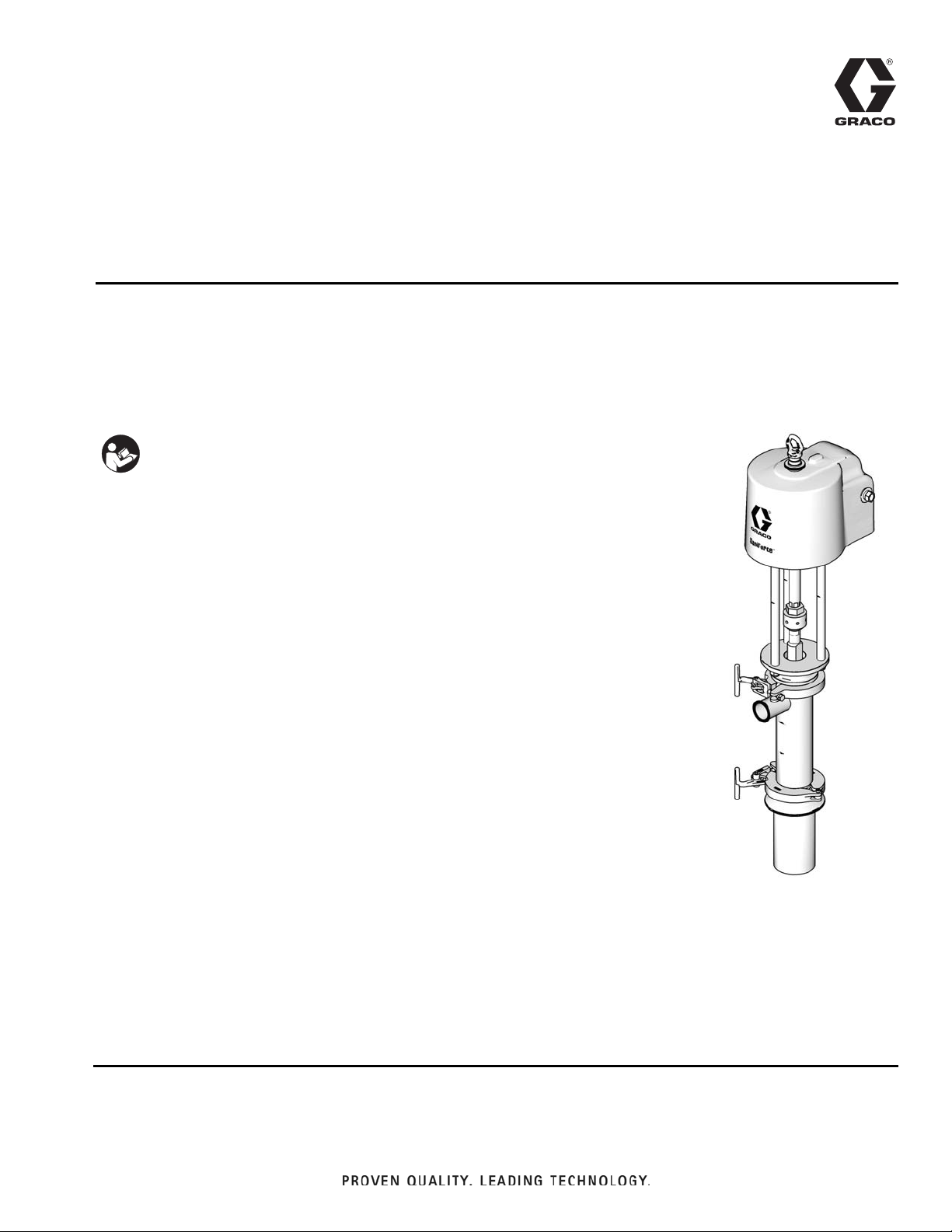
™
SaniForce
12:1
Sanitary Pumps
For use in sanitary applications to transfer medium to high viscosity fluids.
For professional use only.
See page 2 for model information, including maximum fluid working pressure.
Important Safety Instructions
Read all warnings and instructions in this
manual. Save these instructions.
3A0735J
EN
Page 2

Models
Contents
Models . . . . . . . . . . . . . . . . . . . . . . . . . . . . . . . . . . . 2
Warnings . . . . . . . . . . . . . . . . . . . . . . . . . . . . . . . . . 4
Installation . . . . . . . . . . . . . . . . . . . . . . . . . . . . . . . . 6
Grounding . . . . . . . . . . . . . . . . . . . . . . . . . . . . . . 6
Mounting . . . . . . . . . . . . . . . . . . . . . . . . . . . . . . . 6
Setup . . . . . . . . . . . . . . . . . . . . . . . . . . . . . . . . . . 6
Operation . . . . . . . . . . . . . . . . . . . . . . . . . . . . . . . . . 8
Pressure Relief Procedure . . . . . . . . . . . . . . . . . 8
Flush Before First Use . . . . . . . . . . . . . . . . . . . . 8
Adjusting the Pump Speed and Pressure . . . . . . 8
Pump Shutdown . . . . . . . . . . . . . . . . . . . . . . . . . 8
Maintenance . . . . . . . . . . . . . . . . . . . . . . . . . . . . . . . 9
Flushing Procedure . . . . . . . . . . . . . . . . . . . . . . . 9
Cleaning Procedure . . . . . . . . . . . . . . . . . . . . . . 9
Tighten Connections . . . . . . . . . . . . . . . . . . . . . . 9
Troubleshooting . . . . . . . . . . . . . . . . . . . . . . . . . . . 10
Models
Service . . . . . . . . . . . . . . . . . . . . . . . . . . . . . . . . . . 11
Disconnect the Pump . . . . . . . . . . . . . . . . . . . . 11
Disassemble the Pump . . . . . . . . . . . . . . . . . . . 11
Reassemble the Pump . . . . . . . . . . . . . . . . . . . 13
Reconnect the Pump . . . . . . . . . . . . . . . . . . . . . 14
Parts . . . . . . . . . . . . . . . . . . . . . . . . . . . . . . . . . . . . 16
Complete Pump Models 24F625
and 24F626 . . . . . . . . . . . . . . . . . . . . . . . . . 16
Kits . . . . . . . . . . . . . . . . . . . . . . . . . . . . . . . . . . . 17
Displacement Pump Models 24G761
and 24G762 . . . . . . . . . . . . . . . . . . . . . . . . 18
Displacement Pump Models 24G761
and 24G762 . . . . . . . . . . . . . . . . . . . . . . . . 19
Kits . . . . . . . . . . . . . . . . . . . . . . . . . . . . . . . . . . . 19
Dimensions . . . . . . . . . . . . . . . . . . . . . . . . . . . . . . . 21
Performance Chart . . . . . . . . . . . . . . . . . . . . . . . . . 22
Technical Data . . . . . . . . . . . . . . . . . . . . . . . . . . . . 23
Graco Standard Warranty . . . . . . . . . . . . . . . . . . . 24
Maximum Air Inlet Pressure: 100 psi (0.7 MPa, 6.9 bar)
Maximum Fluid Working Pressure: 1450 psi (10.1 MPa, 100.4 bar)
Pump
Model
24F625 24G761 Priming Piston Stubby Acetal, PTFE, Nitrile, and UHMWPE
24F626 24G762 Priming Piston Stubby, with extra seal* Acetal, PTFE, Nitrile, and UHMWPE
* For use with viscous, sticky material.
Displacement
Pump Model
Pump Type Pump Description Packings
2 3A0735J
Page 3

Material Certification
Reference: SaniForce Product Family
Issue Date: September 14, 2011
All fluid contact materials in the SaniForce product family are FDA-Compliant and meet the United States
Code of Federal Regulations (CFR) Title 21, Section 177 or are of a corrosion resistant grade Stainless
Steel. This includes the below product groups:
1. SaniForce 1040, 1590, 2150 Air-Operated Double Diaphragm Pumps
2. SaniForce 1590, 3150 HS Air-0perated Double Diaphragm Pumps
3. SaniForce 1590, 3150 HS 3-A Certified Air-Operated Double Diaphragm Pumps
4. SaniForce 5:1, 6:1 and 12:1 Air-Operated Piston Pumps
5. SaniForce Diaphragm Pump and Piston Pump Drum Unloaders
6. SaniForce Diaphragm Pump and Piston Pump Bin Evacuation Systems
Bradley A. Byron
Quality Manager
Graco Inc.
Models
3A0735J 3
Page 4
Warnings
WARNINGWARNINGWARNING
WARNING
Warnings
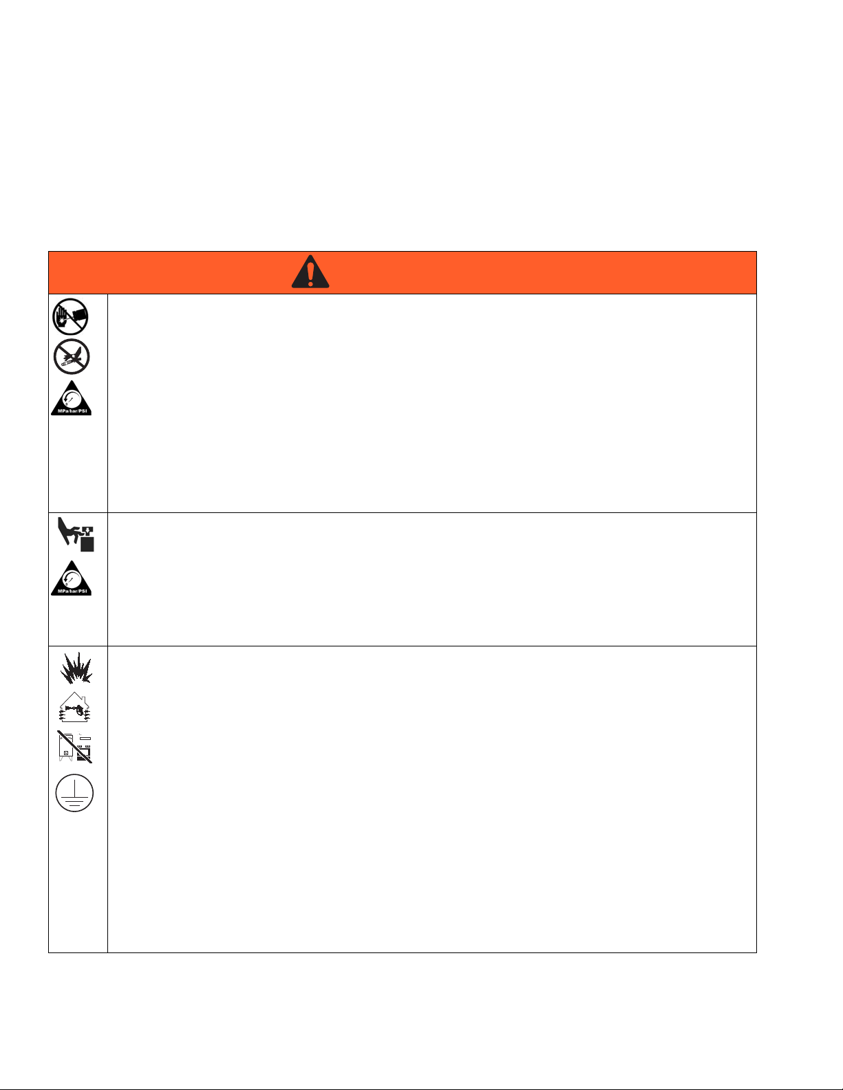
The following warnings are for the setup, use, grounding, maintenance, and repair of this equipment. The exclamation point symbol alerts you to a general warning and the hazard symbols refer to procedure-specific risks. When
these symbols appear in the body of this manual, refer back to these Warnings. Product-specific hazard symbols and
warnings not covered in this section may appear throughout the body of this manual where applicable.
SKIN INJECTION HAZARD
High-pressure fluid from dispensing device, hose leaks, or ruptured components will pierce skin. This may
look like just a cut, but it is a serious injury that can result in amputation. Get immediate surgical
treatment.
+
• Do not point dispensing device at anyone or at any part of the body.
• Do not put your hand over the fluid outlet.
• Do not stop or deflect leaks with your hand, body, glove, or rag.
• Follow the Pressure Relief Procedure when you stop dispensing and before cleaning, checking, or
servicing equipment.
• Tighten all fluid connections before operating the equipment.
• Check hoses and couplings daily. Replace worn or damaged parts immediately.
MOVING PARTS HAZARD
Moving parts can pinch, cut or amputate fingers and other body parts.
• Keep clear of moving parts.
• Do not operate equipment with protective guards or covers removed.
• Pressurized equipment can start without warning. Before checking, moving, or servicing equipment,
follow the Pressure Relief Procedure and disconnect all power sources.
FIRE AND EXPLOSION HAZARD
Flammable fumes, such as solvent and paint fumes, in work area can ignite or explode. To help prevent
fire and explosion:
• Use equipment only in well ventilated area.
• Eliminate all ignition sources; such as pilot lights, cigarettes, portable electric lamps, and plastic drop
cloths (potential static arc).
• Keep work area free of debris, including solvent, rags and gasoline.
• Do not plug or unplug power cords, or turn power or light switches on or off when flammable fumes are
present.
• Ground all equipment in the work area. See Grounding instructions.
• Use only grounded hoses.
• Hold gun firmly to side of grounded pail when triggering into pail.
• If there is static sparking or you feel a shock, stop operation immediately. Do not use equipment until
you identify and correct the problem.
• Keep a working fire extinguisher in the work area.
4 3A0735J
Page 5
Warnings
WARNINGWARNINGWARNING
WARNING
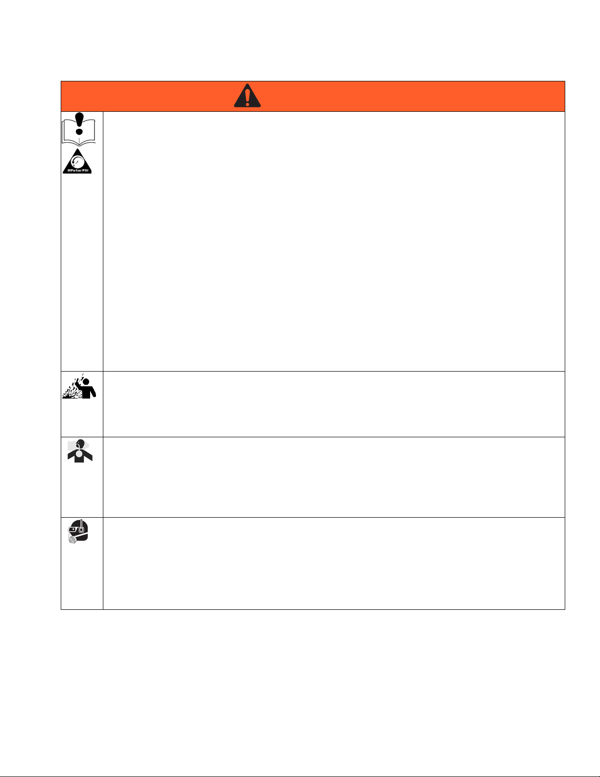
EQUIPMENT MISUSE HAZARD
Misuse can cause death or serious injury.
• Do not operate the unit when fatigued or under the influence of drugs or alcohol.
• Do not exceed the maximum working pressure or temperature rating of the lowest rated system
component. See Technical Data in all equipment manuals.
• Use fluids and solvents that are compatible with equipment wetted parts. See Technical Data in all
equipment manuals. Read fluid and solvent manufacturer’s warnings. For complete information about
your material, request MSDS from distributor or retailer.
• Do not leave the work area while equipment is energized or under pressure. Turn off all equipment and
follow the Pressure Relief Procedure when equipment is not in use.
• Check equipment daily. Repair or replace worn or damaged parts immediately with genuine
manufacturer’s replacement parts only.
• Do not alter or modify equipment.
• Use equipment only for its intended purpose. Call your distributor for information.
• Route hoses and cables away from traffic areas, sharp edges, moving parts, and hot surfaces.
• Do not kink or over bend hoses or use hoses to pull equipment.
• Keep children and animals away from work area.
• Comply with all applicable safety regulations.
SPLATTER HAZARD
Hot or toxic fluid can cause serious injury if splashed in the eyes or on skin. During blow off of platen,
splatter may occur.
• Use minimum air pressure when removing platen from drum.
TOXIC FLUID OR FUMES HAZARD
Toxic fluids or fumes can cause serious injury or death if splashed in the eyes or on skin, inhaled, or
swallowed.
• Read MSDSs to know the specific hazards of the fluids you are using.
• Store hazardous fluid in approved containers, and dispose of it according to applicable guidelines.
PERSONAL PROTECTIVE EQUIPMENT
You must wear appropriate protective equipment when operating, servicing, or when in the operating area
of the equipment to help protect you from serious injury, including eye injury, hearing loss, inhalation of
toxic fumes, and burns. This equipment includes but is not limited to:
• Protective eyewear, and hearing protection.
• Respirators, protective clothing, and gloves as recommended by the fluid and solvent manufacturer.
3A0735J 5
Page 6
Installation
Installation
Grounding
The equipment must be grounded. Grounding
reduces the risk of static and electric shock by
providing an escape wire for the electrical current
due to static build up or in the event of a short circuit.
Pump: Connect a ground wire (Graco PN 238909) to
the ground screw on the bottom cover of the air motor,
under the shroud. Connect the other end of the ground
wire to a true earth ground.
Air and fluid hoses: use only electrically conductive
hoses with a maximum of 500 ft. (150 m) combined
hose length to ensure grounding continuity. Check electrical resistance of hoses. If total resistance to ground
exceeds 25 megohms, replace hose immediately.
Air compressors: follow manufacturer’s recommendations.
Dispense valve: ground through connection to a properly grounded fluid hose and pump.
Material supply container: follow local code.
Mounting
To avoid injury from a falling pump, check the torque
on the lift ring (16) and nut (15) before using the lift
ring to lift the pump. Torque to 30-36 ft-lb
(41-49 N•m).
Mount the pump on a surface than can support the
weight of the pump and accessories, as well as the
stress caused during operation. Do not use air or fluid
lines to support the pump.
Setup
To avoid contaminating the fluid, pipe the exhaust air
to vent outside of the fluid product area, away from
people, animals, or food-handling areas.
NOTE: Reference numbers and letters in parentheses in
the text refer to the callouts in the figures and the parts
drawings.
Container(s) that receive material: follow local code.
Solvent pails used when flushing: follow local code.
Use only conductive metal pails, placed on a grounded
surface. Do not place the pail on a nonconductive surface, such as paper or cardboard, which interrupts
grounding continuity.
To maintain grounding continuity when flushing or
relieving pressure: hold metal part of the dispense
valve firmly to the side of a grounded metal pail, then
trigger the valve.
6 3A0735J
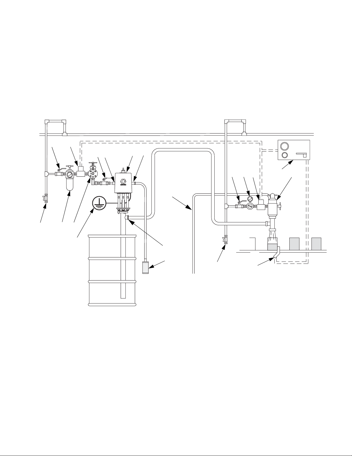
Accessories are available from Graco. Make certain all
accessories are sized and pressure-rated to meet your
system requirements.
F
IG. 1 is only a guide for selecting and installing system
components and accessories. Contact your Graco distributor for assistance in designing a system to suit your
particular needs.
Install a bleed-type master air valve (G) close to the
pump air inlet (D), to relieve air trapped between it and
the air motor.
Install an air filter/regulator (F) in the pump air line,
upstream from the bleed valve, to control air inlet pressure and to remove harmful dirt and contaminants from
your compressed air supply.
Page 7
Installation
B
CDG
FJ
GH
A
E
N
J
G M
K
L
P
H
Main Air Line
ti15638a
R
S
Install a pump runaway valve (S) in the pump air line to
shut off air to the air motor automatically if the pump
starts to run too fast.
Install another bleed-type master air valve (G) upstream
from all air line accessories and use it to isolate the
accessories during cleaning and repair.
On the air drop to the dispense valve (K), install an air
regulator (M) to control air pressure to the valve. Install a
bleed valve (G) to use as a shutoff when servicing the
dispense valve.
Connect air solenoid valves (H) to a timer control (L),
and set so the dispense valve (K) will dispense at proper
intervals.
FIG. 1. Typical installation
Key:
Pump Components (Included)
A Bung-Mounted Sanitary Pump
B Air Exhaust Muffler (may alternately be mounted remotely,
using exhaust hose)
C 3/4 npt Exhaust Air Outlet
D 1/2 npt Air Inlet
E 1-1/2 in. Tube Size Flanged Fluid Outlet
3A0735J 7
System Components/Accessories (sold separately)
F Air Line Filter/Regulator
G Bleed-Type Master Air Valve (required)
H Air Solenoid Valve
J Air Line Drain Pipe and Valve
K Dispensing Valve
L Timer Control
M Air Regulator
N Dispensing Valve Air Exhaust Hose
P Sensing Device
R Pump Ground Wire (required)
S Pump Runaway Valve
Page 8
Operation
Operation
NOTICE
Do not expose the air motor to temperatures higher
than 120°F (49°C) or the immersed fluid pump to temperatures higher than 160°F (71°C). Excessive temperatures may damage the pump packings and seals.
Pressure Relief Procedure
Trapped air can cause the pump to cycle
unexpectedly, which could result in serious injury from
injection, splashing, or moving parts. Relieve pressure
when you stop pumping and before cleaning,
checking, or servicing equipment.
1. Shut off the air supply to the pump.
2. Close the bleed-type master air valve (required in
system).
3. Open the fluid ball valve and/or dispensing valve to
relieve fluid pressure.
Adjusting the Pump Speed and Pressure
Set pressure regulator to 0 psi. Open the bleed-type
master air valve. Adjust the pump air regulator until the
pump is running smoothly.
Allow the pump to cycle slowly until all air is pushed out
of the lines (the fluid will flow in a steady stream from the
fluid outlet) and the pump is primed.
With the air supply turned on, the pump will start when
the dispensing valve is opened and stall against pressure when the valve is closed. In a circulating system,
the pump operates until the air supply is turned off.
NOTICE
Never allow the pump to run dry of fluid. A dry pump will
accelerate to a high speed, possibly damaging itself.
If the pump accelerates quickly, or is running too fast,
stop the pump immediately and check the fluid supply. If
the supply is empty and air has been pumped into the
lines, refill the container and prime the pump and lines
with fluid. Be sure to eliminate all air from the system.
Flush Before First Use
The sanitary pump was assembled using sanitary lubricant on moving parts and was tested in water. Flush the
pump thoroughly with an appropriate cleaning solution,
and disassemble and sanitize the parts before using the
pump. See Flushing Procedure, page 9. Check
national, state, and local codes for specific limitations.
Pump Shutdown
Follow the Pressure Relief Procedure, page 8. Always
stop the pump at the bottom of its stroke to prevent fluid
from drying on the displacement rod. (The air motor will
exhaust at the bottom and top of the stroke.)
8 3A0735J
Page 9

Maintenance
Maintenance
Flushing Procedure
NOTE:
• Flush before fluid can dry in the equipment, at the
end of the day, before storing, and before repairing
equipment.
• Flush at the lowest pressure possible. Check connectors for leaks and tighten as necessary.
• Flush with an appropriate cleaning solution.
1. Remove the pump from the fluid container. Operate
it at a slow rate to pump out as much fluid as possible.
2. Follow Pressure Relief Procedure, page 8.
3. Place siphon tube in grounded metal pail containing
an appropriate cleaning solution.
4. Set pump air regulator to lowest possible fluid pressure, and start pump.
2. Flush the system thoroughly with an appropriate
cleaning solution. See Flushing Procedure,
page 9.
3. Follow the Pressure Relief Procedure, page 8.
4. Remove the air and fluid hoses and fittings from the
pump.
5. Ram-Mounted Pumps: Loosen the hand screw
and lift the upper shroud straight up on the rod.
Other Pumps: Remove the upper shroud.
6. Clean thoroughly the surface between the upper
and lower shrouds.
7. Disassemble the fluid pump and accessories. See
Disassemble the Pump, page 11.
8. Wash all pump parts with an appropriate cleaning
solution at the cleaning product manufacturer’s recommended temperature and concentration.
9. Rinse all pump parts again with water and allow
them to dry.
10. Inspect all pump parts and reclean if needed.
5. Run the pump long enough to thoroughly clean the
pump and hoses.
6. Follow Pressure Relief Procedure, page 8.
Cleaning Procedure
NOTE: The following instructions are a basic procedure
for cleaning a sanitary pump.
• Be sure to follow your national and state sanitary
standard codes and local regulations.
• Use appropriate cleaning and disinfecting agents, at
intervals appropriate for product processed.
• Follow cleaning product manufacturer’s instructions.
NOTE: The pump must be disassembled to clean it
thoroughly.
1. Remove the pump from the fluid container. Operate
it at a slow rate to pump out as much fluid as possible.
NOTE: Any damaged rubber parts must be replaced as
they could harbor microorganisms that can contaminate
the fluid.
11. Immerse all pump parts in an appropriate sanitizer
before assembly. Take the pump parts out of the
sanitizer one-by-one as needed.
12. Lubricate the moving pump parts and o-rings, packings, and seals with appropriate waterproof sanitary
lubricant.
13. Circulate the sanitizing solution through the pump
and the system prior to use.
14. Ram-Mounted Pumps: Clean all ram surfaces.
Remove and clean the inflatable seal and ram plate.
See Manual 3A0591.
Tighten Connections
Before each use, check all hoses for wear or damage.
Replace as necessary. Check that all connections are
tight and leak-free.
3A0735J 9
Page 10

Troubleshooting
Troubleshooting
Problem Cause Solution
1. Follow Pressure Relief Procedure, page 8.
2. Check all possible remedies in the Troubleshooting
Chart before disassembling the pump.
Pump fails to operate. Restricted air line or inadequate air
supply.
Insufficient air pressure; closed or
clogged air valves, etc.
Exhausted fluid supply. Refill fluid supply.
Damaged air motor. Service.
Pump operates, but output low on
both strokes.
Pump operates, but output low on
down stroke.
Pump operates, but output low on up
stroke.
Erratic or accelerated operation. Exhausted fluid supply. Refill fluid supply.
Restricted air line or inadequate air
supply.
Insufficient air pressure; closed or
clogged air valves, etc.
Exhausted fluid supply. Refill fluid supply.
Obstructed fluid line, valves, dispens-
ing valve, etc.
Worn throat packing (103). Replace throat packing.
Damaged cylinder o-ring (123). Replace o-ring.
Held open or worn fluid inlet valve. Clear or service fluid inlet valve.
Damaged cylinder o-ring (123). Replace o-ring.
Held open or worn fluid piston or seal
(109, 110).
Held open or worn fluid inlet valve. Clear or service fluid inlet valve.
Held open or worn fluid piston or seal
(109, 110).
Clear air line or increase air supply.
Open or clean air valves, etc.
Clear air line or increase air supply.
Open or clean air valves, etc.
Clear. Relieve pressure and disconnect fluid line. Turn on air. If pump
starts, the fluid line is clogged.
Clear or service fluid piston or seal.
Clear or service fluid piston or seal.
10 3A0735J
Page 11

Service
ti15575a
ti15576a
ti15565a
ti15566a
101
123
105/106
113
102
119
120
122
121
115
118
Service
Disconnect the Pump
Moving parts can pinch, cut or amputate fingers and
other body parts. Keep your hands and fingers away
from the priming piston during operation and
whenever the pump is charged with air.
1. Remove the pump from the fluid container. Operate
it at a slow rate to pump out as much fluid as possible.
2. Follow the Pressure Relief Procedure, page 8.
3. Remove the air and fluid hoses from the pump.
Ram-mounted pumps: leave ram air connected for
now.
4. Hold the reducer fitting with
a wrench. Use a spanner
wrench to loosen the coupling nut.
5. Lower the coupling nut
enough to remove the coupling collars.
Disassemble the Pump
NOTE: Pump Repair Kits are available. Purchase the kit
separately. See the Parts list on page 19 to select the
correct kit for your pump. Kit parts are marked with an *.
1. With the pump on its side, tap the displacement rod
(105) with a rubber mallet to drive the priming piston
assembly out of the base (102).
2. Hold the valve plate guide
(119) with a wrench. Use
another wrench to remove
the priming piston nut (122).
3. Remove the priming piston
(121) and the valve plate
(120).
4. Remove the clamp (118) from the base (102). Then
remove the base (102). Tap with a rubber mallet to
loosen, if needed.
5. Remove the o-ring (123) and the spacer (113). Tap
the displacement rod again to drive the displacement rod/priming piston rod assembly (105/106) out
of the cylinder (101).
6. Hold the rod (106) with a wrench and remove the
priming piston guide (119).
6. Remove the clamps holding the pump base to the
ram or drum. Ram-mounted pumps: Use the ram
to lift the air motor. Disconnect air lines.
7. Remove the clamp holding the displacement pump
to the air motor. Carry the displacement pump to the
bench for service.
3A0735J 11
FIG. 2. Remove piston rod
Page 12

Service
116a
116b
116c
116d
117
115
ti15568a
ti15570a
ti15571a
108
*109
107
*110
106
ti15569a
103a
103b*
*103c
*103d
7. Hold the piston rod (106) with a wrench. Use
another wrench to loosen the intake valve housing
(115), then remove it. If the intake valve housing
(115) is stuck to the rod, tap with a plastic rod and
mallet.
8. Screw out the packing nut (117) and remove the
packing stack (116) from the intake valve housing
(115).
FIG. 3. Intake valve housing
9. Remove the valve
plate (112). Use
wrenches on the displacement rod flats
(105) and the piston
rod flats (106) to disconnect.
11. Stand cylinder upright. Remove the u-cup seal
assembly, which includes the base (103a), insert
(103b), o-ring (103d), and u-cup (103c).
FIG. 5. Remove u-cup seal assembly
12. Refer to the Cleaning Procedure on page 9. Clean
the parts and inspect them for wear or damage.
Replace them as necessary.
10. Remove the valve plate (108) and the piston (107).
Remove the bearings (110) from the piston. (Model
24G761 has two bearings; Model 24G762 has three
bearings.)
NOTE: On Displacement Pump Model 24G761, carefully remove the u-cup seal (109). Use a pick, not a
screwdriver, as the packing may deform.
FIG. 4. Remove piston and seals
12 3A0735J
Page 13

Service
116a
116b
116c
116d
117
115
ti15568a
123*
112
113
ti15798a
Reassemble the Pump
NOTE: Any damaged rubber parts must be replaced as
they could harbor microorganisms that can contaminate
the fluid.
NOTE: Lubricate the o-rings, throat packings, and piston
seals with appropriate waterproof sanitary lubricant
prior to installation.
1. Install the bearings (110*) and the u-cup seal (109*,
24G761 only) on the piston (107). The lips of the
piston u-cup must face up. Install the valve plate
(108) and piston assembly on the displacement rod
(105). Cutout on piston must face down.
2. Use wrenches on the displacement rod flats and the
piston rod flats to reconnect. Torque to 60-70 ft-lb
(81-95 N•m).
3. Install the packing stack (116*) into the intake valve
housing (115). Maintain the following order: shims
(116a), female gland (116b), five v-packings (116c)
with the lips facing up, and male gland (116d).
Loosely thread packing nut (117) into the valve
housing (115).
7. Turn the pump on its side. Use a rubber mallet to tap
the displacement rod so the piston rod extends well
out of the cylinder.
8. Install the valve plate (112) and the spacer (113)
into the bottom of the cylinder. Install the cylinder
o-ring (123*).
FIG. 7. Valve plate
9. Lubricate the piston rod and the inside of the packing nut (117) and intake valve housing (115). Slide
the assembly onto the piston rod, then use two
wrenches to tighten the valve housing.
FIG. 6. Intake valve housing
4. Install the u-cup (103c*) and insert (103b*) into the
u-cup seal assembly base (103a). Throat u-cup lips
must face down. Then install the o-ring (103d*).
5. Lubricate the displacement rod/piston rod assembly
and slide into the cylinder from the top.
6. Install the u-cup assembly (103) in the top of the cylinder (101). Reassembly may be difficult. Use
steady force until the assembly drops into place.
10. Stand the pump upright, placing the cylinder (101)
into the base (102). Reattach the clamp to hold the
base (102) to the cylinder (101). Replace the pin
(125).
11. Turn the pump on its side. Use a rubber mallet to tap
the displacement rod so the piston rod extends well
out of the cylinder.
12. Hold the displacement rod (105) with a wrench.
Screw on the guide (119) and use another wrench
to tighten.
13. Install the valve plate (120) and the priming piston
(121). Hand tighten the priming piston nut (122).
14. Hold the displacement rod (105) with a wrench. Use
another wrench to tighten the priming piston nut
(122).
3A0735J 13
Page 14

Service
Reconnect the Pump
1. Ram-mounted pumps: Set the displacement pump
in place, then attach the clamp. Align the air motor
and set it on top of the displacement pump. Attach
the clamp. Replace the pin.
2. Other pumps: Slide the assembled displacement
pump into position on the air motor pump adapter
and reattach the clamp.
3. Hold the motor shaft up with one hand. With your
other hand, put the coupling nut (5) on the rod.
4. Put the coupling collars (4) into the coupling nut so
large flanges point upward.
5. Gently let the motor shaft drop onto the rod. Use a
spanner wrench to tighten the coupling nut securely.
6. Connect the remaining air and fluid hoses and the
ground wire.
14 3A0735J
Page 15

Service
3A0735J 15
Page 16

Parts
1
2
3
4
5
6
7
8
10
10
9
12
13
14
15
16
18
19
20
Apply PTFE tape to threads.
1
Hand tighten only.
2
Apply sanitary lubricant.
3
20
ti16013a
21a
21b
22
23
Complete Pump Models 24F625
and 24F626
1
5
3
3
21b
3
2
21c
3
5
Apply medium-strength (blue) thread
locker.
4
4
Apply an appropriate medium-strength thread
locker on the lift ring (16) and nut (15) every
time it is installed to prevent it from coming
loose during operation. Torque to 30-36 ft-lb
(41-49 N•m). Do not over tighten.
5
Parts
16 3A0735J
Page 17

Complete Pump Models 24F625 and 24F626
Parts
Ref Part Description Qty
1 24G787 MOTOR, SaniForce; 7.5 in.; see
manual 3A1211
2 DISPLACEMENT PUMP 1
24G761 Model 24F625
24G762 Model 24F626
3 16A939 COUPLER 1
4 184130 COLLAR, coupling 2
5 626045 COUPLING 1
6 16C010 TIE ROD, 13.3 in. (338 mm)
between shoulders
7 102216 NUT, lock, 5/8-11, sst 3
8 16G380 SHROUD, upper; includes grom-
mets (Ref. 21)
9 16G382 SHROUD, lower; includes fasten-
ers (Ref. 10) and grommets
(Ref. 21)
Kits
Muffler Kit 16G390
Ref. Part Description Qty.
18 512914 MUFFLER, polyethylene 2
Exhaust Assembly Kit 16G389
Ref. Part Description Qty.
18 512914 MUFFLER, polyethylene 1
19 ----- HOSE, exhaust, 6 ft. 1
20 101818 CLAMP, hose 2
Ref Part Description Qty
10 118134 SCREW, cap, M8 x 1.25, sst; see
1
Kits
12 24G862 FITTING, air inlet, 1/2 npt,
Includes Ref. 23
13 16C946 FITTING, 3/4 npt 1
14 165053 O-RING, PTFE 1
15 16C306 NUT, hand 1
16 16C009 RING, lift 1
17▲ 280574 LABEL, warning, not shown 1
3
18 512914 MUFFLER; see Kits 1
19 ----- HOSE, exhaust; see 1
20 101818 CLAMP, hose; see Kits 2
1
21 ----- GROMMET; see Kits 6
22 16G084 FITTING, air inlet, 1/2 npt 1
1
23 166702 O-RING, air inlet, buna-n 1
▲ Replacement Danger and Warning labels, tags, and
cards are available at no cost.
Grommet Kit 16G385
Ref. Part Description Qty.
21a* ----- GROMMET, air motor piston
rod
21b ----- GROMMET, air fitting 2
21c ----- ROMMET, tie rod 3
* Order Kit 16G384 for qty. 3 of the piston rod grommet.
4
1
1
Lower Shroud Fastener Kit 16G432
Ref. Part Description Qty.
10 118134 SCREW, cap, M8 x 1.25, sst 4
3A0735J 17
Page 18

Parts
101
102
115
116*
117
103b*
103c*
103a
103d*
104
105
106
108
*109
107
*110
112
113
118
118
123*
121
120
119
122
114
1
108
107
110*
1
ti15562a
125
125
1
1
5
1
7
1
221
2
3
6
1
1
1 4
1
Apply appropriate waterproof, sanitary lubricant.
1
Model 24G761 has a u-cup (109) and two bearings (110).
Model 24G762 has three bearings (110) and no u-cup
(109).
2
Piston u-cup lips must face UP.
3
V-packing lips must face UP.
4
Torque to 60-70 ft-lb (81-95 N•m).
5
Cutout on piston must face DOWN.
6
Throat u-cup lips must face DOWN.
7
6
Displacement Pump Models 24G761 and 24G762
18 3A0735J
Page 19

Displacement Pump Models 24G761 and 24G762
Parts
Ref Part Description Qty
101 16G430 CYLINDER, pump 1
102 16G431 BASE, pump, includes Part 114 1
103a ----- BASE, u-cup; see Kits for
U-Cup Seal Assembly
103b* ----- INSERT; see Kits for U-Cup
Seal Assembly
103c* ----- U-CUP; see Kits for package of
5 with o-ring (part 103d)
103d* ----- O-RING; see Kits for package
of 5 with u-cup (part 103c)
104 16E465 ADAPTER, tie rod 1
105 16G436 ROD, displacement 1
106 16G437 ROD, priming piston 1
107 181892 PISTON, cylinder 1
108 167493 PLATE, piston valve 1
109* 108543 U-CUP, UHMWPE, Model
24G761 only
110* 181897 BEARING
Model 24G761
Model 24G762
112 16A846 PLATE, intake valve 1
Ref Part Description Qty
113 16A847 SPACER 1
114 167481 SEAT, valve 1
115 167482 HOUSING, intake valve seal 1
1
116* ----- STACK, gland/packing 1
117 167486 NUT, packing 1
1
118 16G386 CLAMP, assembly 2
119 167480 GUIDE, valve plate, pump 1
1
120 167479 PLATE, priming piston valve 1
121 172200 PISTON, priming 1
1
122 102533 NUT, plain hex 1
123* 16D164 O-RING, 152, nitrile 1
125 16F603 PIN, locking, 5/16 in. 2
* Parts included in Repair Kit 24G555 (Displacement
Pump Model 24G761) or Repair Kit 24G556 (Dis-
1
2
3
placement Pump Model 24G762).
Kits
U-Cup Seal Assembly Kit 24C623
Ref. Part Description Qty.
103a ----- BASE 1
103b ----- INSERT 1
103c ----- U-CUP SEAL 1
103d ----- O-RING 1
U-Cup Seal/O-Ring Kit 24G858
Ref. Part Description Qty.
103c ----- U-CUP SEAL 4
103d ----- O-RING 4
3A0735J 19
Page 20

Parts
20 3A0735J
Page 21

Dimensions
ti15718a
47.5 in
(121 cm)*
21.1 in.
(54 cm)*
16.1 in.
(41 cm)*
4.1 in.
(10.4 cm)
* Add 4.7 in. (12 cm) to allow for full extension of the priming piston rod.
Dimensions
3A0735J 21
Page 22

Performance Chart
Cycles per Minute
Fluid Flow gpm (lpm) tested in No. 10 weight oil
Fluid Outlet Pressure psi (MPa, bar)
Air Flow scfm (m
3
/min)
KEY
A
=
100 psi (0.7 MPa, 7 bar)
B
=
70 psi (0.5 MPa, 5 bar)
C
=
40 psi (0.3 MPa, 3 bar)
= fluid flow
= air consumption
0
A
B
C
A
B
C
1200
(8.3, 83)
1000
(7.0, 69)
600
(4.1, 41)
400
(2.8, 28)
2.0
(7.6)
6.0
(22.7)
4.0
(15.1)
120
(3.40)
100
(2.83)
60
(1.70)
20
(0.57)
80
(2.27)
40
(1.13)
0
10 16 30 49
0
800
(5.5, 55)
200
(1.4, 14)
1400
(9.7, 97)
23
36
43
8.0
(30.3)
140
(3.96)
56
Performance Chart
22 3A0735J
Page 23

Technical Data
Technical Data
Maximum Fluid Working Pressure . . . . . . . . . . . . . . . . . 1450 psi (10.1 MPa, 100.4 bar)
Maximum Air Inlet Pressure. . . . . . . . . . . . . . . . . . . . . . 100 psi (0.7 MPa, 6.9 bar)
Maximum Recommended Pump Speed . . . . . . . . . . . . 60 cycles/min, 8.5 gpm (32 liters/min) delivery
Air Consumption . . . . . . . . . . . . . . . . . . . . . . . . . . . . . . See Performance Chart, page 22
Pump Cycles per Gallon (3.8 Liters) . . . . . . . . . . . . . . . 7.1
Ratio . . . . . . . . . . . . . . . . . . . . . . . . . . . . . . . . . . . . . . . 12:1
Maximum Operating Temperature . . . . . . . . . . . . . . . . . 160°F (71°C)
Maximum Ambient Temperature (air motor) . . . . . . . . . 120°F (49°C)
Air Inlet. . . . . . . . . . . . . . . . . . . . . . . . . . . . . . . . . . . . . . 1/2 in. npt(f)
Air Exhaust . . . . . . . . . . . . . . . . . . . . . . . . . . . . . . . . . . 3/4 in. npt(m)
Fluid Inlet Type. . . . . . . . . . . . . . . . . . . . . . . . . . . . . . . . 4.1 in. (10.4 cm) tube with flange for 6 in. (15.2 cm)
Tri-Clamp
Fluid Outlet . . . . . . . . . . . . . . . . . . . . . . . . . . . . . . . . . .
Weight . . . . . . . . . . . . . . . . . . . . . . . . . . . . . . . . . . . . . . 122 lb (55.3 kg)
Wetted Parts . . . . . . . . . . . . . . . . . . . . . . . . . . . . . . . . . stainless steel (300 series or other corrosion-resistant
Sound data
Sound power* . . . . . . . . . . . . . . . . . . . . . . . . . . . . . .
Sound pressure** . . . . . . . . . . . . . . . . . . . . . . . . . . .
2 in. (5.1 cm) Tri-Clamp
grades), Acetal, Buna-N, PTFE, UHMWPE
77.2 dBA
70.5 dBA
®
®
* Sound power at 70 psi (0.48 MPa, 4.8 bar), 20 cpm. Sound power measured per ISO-9614-2.
** Sound pressure was tested 3.28 feet (1 m) from equipment.
3A0735J 23
Page 24

Graco Standard Warranty
Graco warrants all equipment referenced in this document which is manufactured by Graco and bearing its name to be free from defects in
material and workmanship on the date of sale to the original purchaser for use. With the exception of any special, extended, or limited warranty
published by Graco, Graco will, for a period of twelve months from the date of sale, repair or replace any part of the equipment determined by
Graco to be defective. This warranty applies only when the equipment is installed, operated and maintained in accordance with Graco’s written
recommendations.
This warranty does not cover, and Graco shall not be liable for general wear and tear, or any malfunction, damage or wear caused by faulty
installation, misapplication, abrasion, corrosion, inadequate or improper maintenance, negligence, accident, tampering, or substitution of
non-Graco component parts. Nor shall Graco be liable for malfunction, damage or wear caused by the incompatibility of Graco equipment with
structures, accessories, equipment or materials not supplied by Graco, or the improper design, manufacture, installation, operation or
maintenance of structures, accessories, equipment or materials not supplied by Graco.
This warranty is conditioned upon the prepaid return of the equipment claimed to be defective to an authorized Graco distributor for verification of
the claimed defect. If the claimed defect is verified, Graco will repair or replace free of charge any defective parts. The equipment will be returned
to the original purchaser transportation prepaid. If inspection of the equipment does not disclose any defect in material or workmanship, repairs will
be made at a reasonable charge, which charges may include the costs of parts, labor, and transportation.
THIS WARRANTY IS EXCLUSIVE, AND IS IN LIEU OF ANY OTHER WARRANTIES, EXPRESS OR IMPLIED, INCLUDING BUT NOT LIMITED
TO WARRANTY OF MERCHANTABILITY OR WARRANTY OF FITNESS FOR A PARTICULAR PURPOSE.
Graco’s sole obligation and buyer’s sole remedy for any breach of warranty shall be as set forth above. The buyer agrees that no other remedy
(including, but not limited to, incidental or consequential damages for lost profits, lost sales, injury to person or property, or any other incidental or
consequential loss) shall be available. Any action for breach of warranty must be brought within two (2) years of the date of sale.
GRACO MAKES NO WARRANTY, AND DISCLAIMS ALL IMPLIED WARRANTIES OF MERCHANTABILITY AND FITNESS FOR A
PARTICULAR PURPOSE, IN CONNECTION WITH ACCESSORIES, EQUIPMENT, MATERIALS OR COMPONENTS SOLD BUT NOT
MANUFACTURED BY GRACO. These items sold, but not manufactured by Graco (such as electric motors, switches, hose, etc.), are subject to
the warranty, if any, of their manufacturer. Graco will provide purchaser with reasonable assistance in making any claim for breach of these
warranties.
In no event will Graco be liable for indirect, incidental, special or consequential damages resulting from Graco supplying equipment hereunder, or
the furnishing, performance, or use of any products or other goods sold hereto, whether due to a breach of contract, breach of warranty, the
negligence of Graco, or otherwise.
FOR GRACO CANADA CUSTOMERS
The Parties acknowledge that they have required that the present document, as well as all documents, notices and legal proceedings entered into,
given or instituted pursuant hereto or relating directly or indirectly hereto, be drawn up in English. Les parties reconnaissent avoir convenu que la
rédaction du présente document sera en Anglais, ainsi que tous documents, avis et procédures judiciaires exécutés, donnés ou intentés, à la suite
de ou en rapport, directement ou indirectement, avec les procédures concernées.
Graco Information
For the latest information about Graco products, visit www.graco.com.
For patent information, see www.graco.com/patents.
TO PLACE AN ORDER, contact your Graco distributor or call to identify the nearest distributor.
Phone: 612-623-6921 or Toll Free: 1-800-328-0211 Fax: 612-378-3505
All written and visual data contained in this document reflects the latest product information available at the time of publication.
GRACO INC. AND SUBSIDIARIES • P.O. BOX 1441 • MINNEAPOLIS MN 55440-1441 • USA
Copyright 2010, Graco Inc. All Graco manufacturing locations are registered to ISO 9001.
Graco reserves the right to make changes at any time without notice.
Original instructions. This manual contains English. MM 3A0735
Graco Headquarters: Minneapolis
International Offices: Belgium, China, Japan, Korea
www.graco.com
Revision J, December 2014
 Loading...