

Page 1
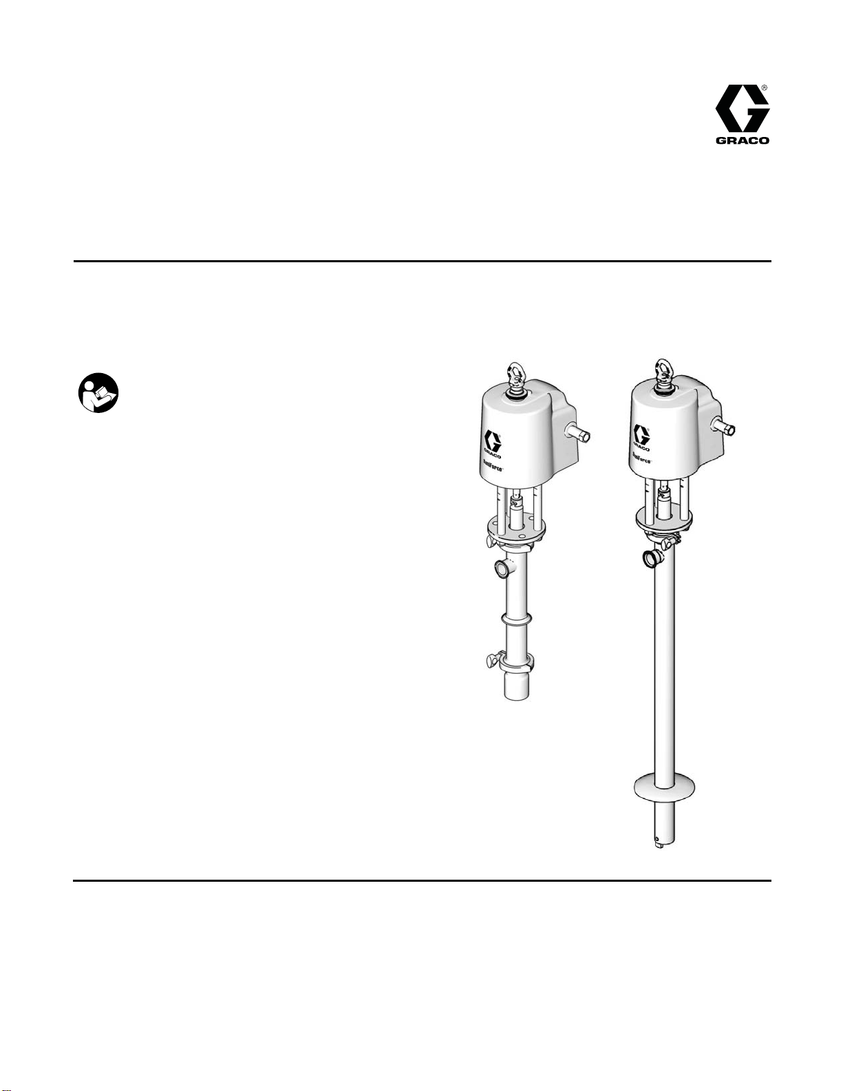
Instructions and Parts
SaniForce™ 6:1
Sanitary
3A0733H
Pumps
For use in sanitary applications to transfer medium to high viscosity fluids. For professional use
only.
Important Safety Instructions
Read all warnings and instructions in this manual.
Save these instructions.
Model 24E836
Model 24G740
EN
PROVEN QUALITY. LEADING TECHNOLOGY.
ti15637a
ti15721a
Page 2

Contents
Models............................................................... 3
Warnings ........................................................... 5
......................................................................... 5
Installation.......................................................... 7
Grounding ................................................... 7
Mounting ..................................................... 7
Setup .......................................................... 7
Operation........................................................... 9
Pressure Relief Procedure............................ 9
Flush Before First Use.................................. 9
Adjusting the Pump Speed and
Pressure ........................................ 9
Pump Shut Down ......................................... 9
Maintenance ...................................................... 10
Flushing Procedure ...................................... 10
Cleaning...................................................... 10
Tighten Threaded Connections..................... 10
Troubleshooting.................................................. 11
Priming P
iston Service ........................................ 12
Disconn
Disasse
ect the Pump ................................... 12
mble the Pump................................. 12
Reassemble After Cleaning .......................... 13
Double Ball Service ............................................ 14
Disconnect the Pump ................................... 14
Disassemble the Pump................................. 15
Reassemble After Cleaning .......................... 15
Parts.................................................................. 16
Kits.................................................................... 17
Priming Piston Displacement Pump Models
24G747 and 24G746 ............................. 18
Double bal
Double-Ball Displacement Pump Models
Notes ............................................................... 24
Product D
Performance chart .............................................. 26
Technical Data ...................................................27
Graco St
l Displacement Pump Models
24G748, 24
24G750 ................................................ 20
24G752 and 24G751 ............................. 22
imensions............................................ 25
andard Warranty.................................... 28
G749, 24G753, and
2
3A0733H
Page 3

Models
Models
Maximum Air In
let Pressure: 100 psi (0.7 MPa, 6.9 bar)
Maximum Fluid
Pump
Model
24E836
24E837
24E838
24E839
24E840
24F942
24G739 24G747
24G740 24G748
Displacement
Pump Model
24G746
24G751
24G752
24G753
24G749
24G750
Working Pressure: 650 psi (4.5 MPa, 44.8 bar)
Pump Type Pump Length De
Priming
Piston
Double Ball
Double Ball
Double Ball Drum Length PTFE
Double Ball Drum Length Buna-N, Nitrile, Nylon, and
Double Ball Bin Length Buna-N, Nitrile, Nylon, and
Priming
Piston
Double Ball Drum Length, with Flange Buna-N, Nitrile, Nylon, and
Stubby
Stubby
Stubby
Stubby, with Flange
scription
Packings
Buna-N, Nitrile, Nylon, and
Polychloroprene
PTFE
Buna-N, Polychloroprene, and
UHMWPE
Polychloroprene
Polychloroprene
Buna-N,
Polychl
Polychloroprene
Nitrile, Nylon, and
oroprene
3A0733H 3
Page 4
Models
4
3A0733H
Page 5
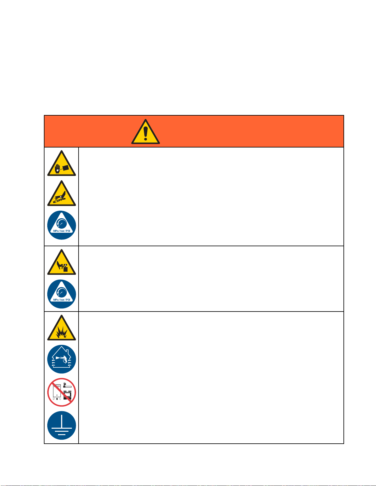
Warnings
Warnings
The following warnings are for the setup, use, grounding, maintenance and repair of this equipment. The
exclamation point symbol alerts you to a general warning and the hazard symbol refers to procedure-specific
risks. When these symbols appear in the body of this manual refer back to these Warnings. Product-specific
hazard symbols and warnings not covered in this section may appear throughout the body of this manual
where applicable.
WARNING
SKIN INJECTION HAZARD
High-pressure fluid from dispensing device, hose leaks, or ruptured components will pierce
skin. This many look like just a cut, but it is a serious injury that can result in amputation.
Get immediate surgical treatment.
• Do not point dispensing device at anyone or at any part of the body.
• Do not put your hand over the fluid outlet.
• Do not stop or deflect leaks with you hand, body, glove, or rag.
• Follow the Pressure Relief Procedure when you stop dispensing and before cleaning,
checking, or servicing equipment.
• Tighten all fluid connections before operating the equipment.
• Check hoses and couplings daily. Replace work or damaged parts immediately.
MOVING PARTS HAZARD
Moving parts can pinch, cut or amputate fingers and other body parts.
• Keep clear of moving parts.
• Do not operate equipment with protective guards or covers removed.
• Pressurized equipment can start without warning. Before checking, moving, or servicing
equipment, follow the Pressure Relief Procedure and disconnect all power sources.
FIRE AND EXPLOSION HAZARD
Flammable fumes, such as solvent and paint fumes, in work area can ignite or explode. To help
prevent fire and explosion:
• Use equipment only in well ventilated area.
• Eliminate all ignition sources; such as pilot lights, cigarettes, portable electric lamps, and
plastic drop cloths (potential static arc).
• Keep work area free of debris, including solvent, rags and gasoline.
• Do not plug or unplug power cords, or turn light switches on or off when flammable fumes
are present.
• Ground all equipment in the work area. See Grounding instructions.
• Use Only grounded hoses.
• Hold gun firmly to side of grounded pail when triggering into pail.
• If there is static sparking or you feel a shock, stop operation immediately. Do not use
equipment until you identify and correct the problem.
• Keep a working fire extinguisher in the work area.
3A0733H 5
Page 6
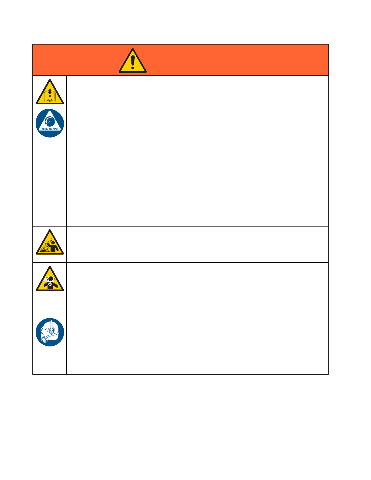
WARNING
EQUIPMENT MISUSE HAZARD
Misuse can cause death or serious injury.
• Do not operat
• Do not exceed the maximum working pressure or temperature rating of the lowest rated
system component. See Technical Data in all equipment manuals.
• Use fluids and solvents that are compatible with equipment wetted parts. See Technical Data
in all equipment manuals. Read fluid and solvent manufacturer’s warnings. For complete
information about your material, request MSDS from distributor or retailer.
• Do not leave
equipment
• Check equipment daily. Repair or replace worn or damaged parts immediately with genuine
manufacturer’s replacement parts only.
• Do not alter or modify equipment.
• Use equip
• Route hoses and cables away from traffic areas, sharp edges, moving parts, and hot surfaces.
• Do not kink or over bend hoses or use hoses to pull equipment.
•Keepchil
• Comply with all applicable safety regulations.
SPLATTER HAZARD
Hot or toxic fluid can cause serious injury if splashed in the eyes or on skin. During blow off of
platen, splatter may occur.
• Use minimum air pressure when removing platen from drum.
TOXIC FLUID OR FUMES
Toxic fluids or fumes can cause serious injury or death if splashed in the eyesoronskin,
inhaled, or swallowed.
e the unit when fatigued or under the influence of drugs or alcohol.
the work area while equipment is energized or under pressure. Turn off all
and follow the Pressure Relief Procedure when equipment is not in use.
ment only for its intended purpose. Call your distributor for information.
dren and animals away from work area.
• Read MSDSs to know the specific hazards of the fluids you are using.
• Store hazardous fluid in approved containers, and dispose of it according to applicable
guidelines.
ONAL PROTECTIVE EQUIPMENT
PERS
ust wear appropriate protective equipment when operating, servicing, or when in the
You m
rating area of the equipment to help protect you from serious injury, including eye injury,
ope
ring loss, inhalation of toxic fumes, and burns. This equipment includes but is not limited to:
hea
• Protective eyewear, and hearing protection.
pirators, protective clothing, and gloves as recommended by the fluid and solvent
•Res
ufacturer.
man
6 3A0733H
Page 7
Installation
Installation
Grounding
The equipment must be grounded. Grounding
reduces the risk of static and electric shock by
providing an escape wire for the electrical current
due to static build up or in the event of a short
circuit.
Pump: Connect a ground wire (Graco PN 238909)
to the ground screw on the bottom cover of the air
motor, under the shield. Connect the other end of the
ground wire to a true earth ground.
Air and fluid hoses: use only electrically conductive
hoses with a maximum of 500 ft. (150 m) combined
hose length to ensure grounding continuity. Check
electrical resistance of hoses. If total resistance
to ground exceeds 25 megohms, replace hose
immediately.
Air compressors: follow manufacturer’s
recommendations.
Dispense valve: ground through connection to a
properly grounded fluid hose and pump.
Material supply container: follow local code.
Container(s) that receive material: follow local code.
Solvent pails used when flushing: follow local
code. Use only conductive metal pails, placed on
a grounded surface. Do not place the pail on a
nonconductive surface, such as paper or cardboard,
which interrupts grounding continuity.
To maintain grounding continuity when flushing or
relieving pressure: hold metal part of the dispense
valve firmly to the side of a grounded metal pail, then
trigger the valve.
Mounting
Mount the pump
weight of the p
stress caused
fluid lines to s
To avoid serious injury, check the torque on the lift
ring (19) and nut (18) before using the lift ring to lift
the pump. Torque to 30–36 ft-lb (41–49 N•m).
on a surface than can support the
ump and accessories, as well as the
during operation. Do not use air or
upport the pump.
Setup
To avoid contaminating the fluid, pipe the exhaust
air to vent outside of the fluid product area, away
from people, animals, or food handling areas.
Note
Reference numbers and letters in
parentheses in the text refer to the callouts in
the figures and the parts drawings.
Accessories are available from Graco. Make certain
all accessories are sized and pressure rated to meet
your system requirements.
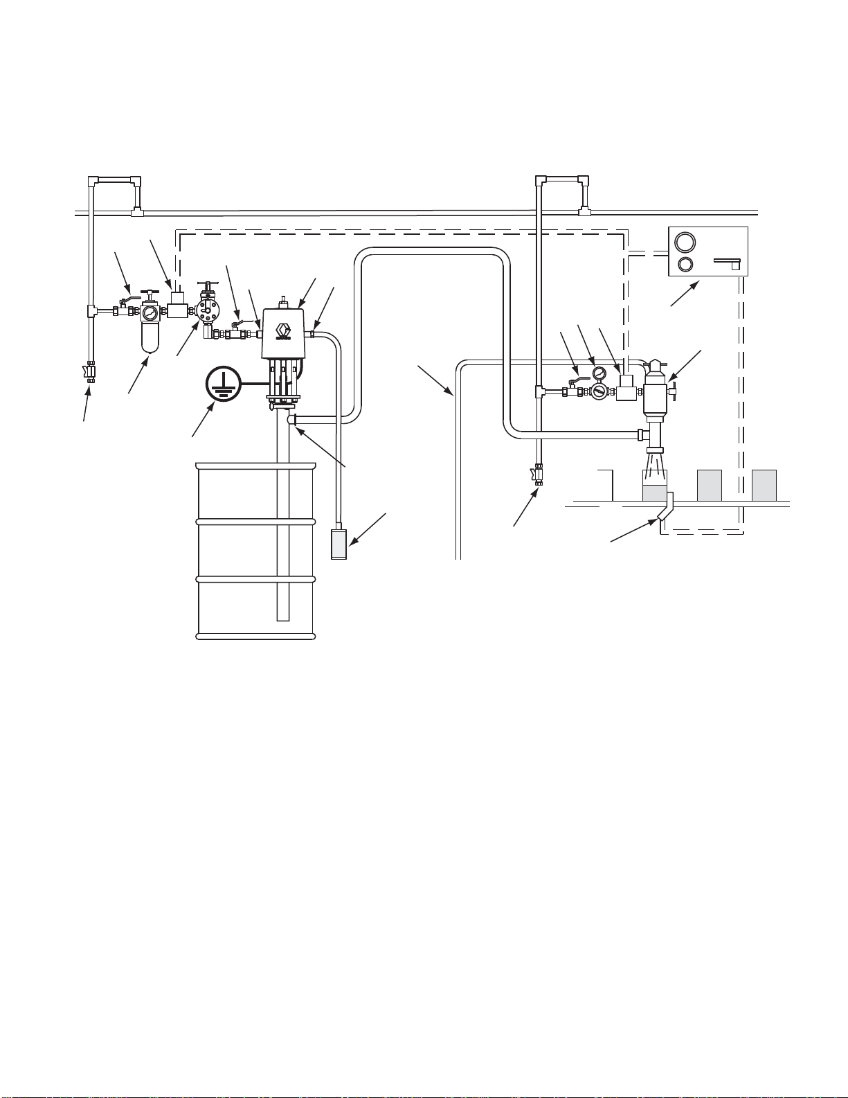
Fig 1 is only a guide for selecting and installing
system components and accessories. Contact your
Graco distributor for assistance in designing a system
to suit your particular needs.
Install a bleed-type master air valve (G) close to the
pump air inlet (D), to relieve air trapped between it
and the air motor.
Install an air filter/regulator (F) in the pump air
line,
upstream from the bleed valve,
air inlet pressure and to remove harmful dirt and
contaminants from your compressed air supply.
to control
3A0733H
Install a pump runaway valve (S) in the pump air line
to shut off air to the air motor automatically if the
pump starts to run too fast.
Install another bleed-type master air valve (G)
upstream from all air line accessories and use it to
isolate the accessories during cleaning and repair.
7
Page 8
Installation
On the air drop to the dispense valve (K), install an
air regulator (M) to control air pressure to the valve.
Install a bleed valve (G) to use as a shutoff when
servicing the dispense valve.
Main Air Line
H
G
G
D
S
F
J
R
A
C
E
Connect air solenoid valves (H) to a timer control
(L), and set so the dispense valve (K) will dispense
at proper intervals.
M
H
G
L
N
B
K
Figure
1 Typical Installation
Key
Pump C
A
B
C 3/4 npt Exhaust Air Outlet
D1/2
E
omponents (Included)
-Mounted Sanitary Pump
Bung
xhaust Muffler (may alternately be mounted
Air E
tely, using exhaust hose)
remo
npt Air Inlet
1-1/2 in. Tube Size Flanged Fluid Outlet
J
m Components/Accessories (sold separately)
Syste
F Air Line Filter/Regulator
GBlee
H
JAir
KDis
L
MAi
NDi
P
R
S
d-Type Master Air Valve (required)
Air Solenoid Valve
Line Drain Pipe and Valve
pensing Valve
Timer Control
r Regulator
spensing Valve Air Exhaust Hose
Sensing Device
Pump Ground Wire (required)
ump Runaway Valve
P
P
TI15638B
8 3A0733H
Page 9
Operation
Operation
NOTICE
Do not expose the air motor to temperatures
higher than 120°F (49°C) or the immersed fluid
pump to temperatures higher than 250°F (121°C).
Excessive temperatures may damage the pump
packings and seals
Pressure Relief Procedure
Trappedaircancausethepumptocycle
unexpectedly, which could result in serious injury
from injection, splashing or moving parts. Relieve
pressure when you stop pumping and before
cleaning, checking, or servicing equipment.
Flushing Procedure, page 10. Check national, state,
and local codes for specific limitations.
Adjusting the Pump Speed and
Pressure
Set pressure regulator to 0 psi. Open the bleed-type
master air valve. Adjust the pump air regulator until
the pump is running smoothly.
Allow the pump to cycle slowly until all air is pushed
out of the lines (the fluid will flow in a steady stream
from the fluid outlet) and the pump is primed.
With the air supply turned on, the pump will start
when the dispensing valve is opened and stall
against pressure when the valve is closed. In a
circulating system, the pump operates until the air
supply is turned off.
NOTICE
Never allow the pump to run dry of fluid. A dry
pump will accelerate to a high speed, possibly
damaging itself.
1. Shut off the air supply to the pump.
2. Close the bleed-type master air valve (required
in system).
3. Open the fluid ball valve and/or dispensing valve
to relieve fluid pressure.
Flush
The sanitary pump was assembled using sanitary
lubricant on moving parts and was tested in
water. Flush the pump thoroughly with an
appropriate cleaning solution or disassemble and
sanitize the parts before using the pump. See
Before First Use
If the pump accelerates quickly, or is running too
fast, stop the pump immediately and check the fluid
supply. If the supply is empty and air has been
pumped into the lines, refill the container and prime
the pump and lines with fluid. Be sure to eliminate all
air from the system.
Pump Shut Down
Follow the Pressure Relief Procedure, page 9 .
Always stop the pump at the bottom of its stroke to
prevent fluid from drying on the displacement rod.
(The air motor will exhaust at the bottom or top of
the stroke.)
3A0733H 9
Page 10

Maintenance
Maintenance
Flushing Procedure
Note:
•Flushbefor
end of the da
equipment
• Flush at the lowest pressure possible. Check
connectors for leaks and tighten as necessary.
• Flush with an appropriate cleaning solution.
1. Remove the pump from the fluid container.
Operate it to pump out as much fluid as possible.
2. Follow the Pressure Relief Procedure, page 9 .
3. Place siphon tube in grounded metal pail
containing an appropriate cleaning solution.
4. Set pump air regulator to lowest possible fluid
pressure, and start pump.
5. Run the pump long enough to thoroughly clean
thepumpandhoses.
6. Follow the .
Cleaning
e fluid can dry in the equipment, at the
y, before storing, and before repairing
.
3. Follow the Pressure Relief Procedure, page 9 .
4. Remove the air and fluid hoses and fittings from
the pump.
5. Ram-Mounted Pumps: Loosen the hand screw
and lift the upper shield straight up on the rod.
Other Pumps: Remove the upper shield.
6. Clean thoroughly the surface between the upper
and lower shields.
7. Disassemble the fluid pump and accessories.
See Priming Piston Service, page 12 or
Double Ball Service, page 14.
8. Wash all pump parts with an appropriate cleaning
solution at the cleaning product manufacturer’s
recommended temperature and concentration.
9. Rinse all pump parts again with water and allow
them to dry.
10. Inspect all pump parts and reclean if needed.
Note
Any damaged rubber parts must
be replaced as they could harbor
microorganisms that can contaminate
the fluid.
11. Immerse all pump parts in an appropriate
sanitizer before assembly. Take the pump parts
out of the sanitizer one-by-one as needed.
12. Lubricate the moving pump parts and o-rings,
packings, and seals with appropriate waterproof
sanitary lubricant.
• Be sur
• Use appropriate cleaning and disinfecting agents,
• Follow cleaning product manufacturer’s
Note
clea
1. Remove the pump from the fluid container.
2. Flush the system thoroughly with an
e to follow your national and state sanitary
ard codes and local regulations.
stand
at intervals appropriate for product processed.
instructions.
: The pump must be disassembled to thoroughly
nit.
Operate it to pump out as much fluid as possible.
appropriate cleaning solution. See
Flushing Procedure, page 10.
13. Circulate the sanitizing solution through the pump
and the system prior to use.
14. Ram-Mounted Pumps: Clean all ram surfaces.
Remove and clean the inflatable seal and ram
plate. See Manual 3A0591.
ten Threaded Connections
Tigh
Before each use, check all hoses for wear or damage.
Replace as necessary. Check that all connections
are tight and leak-free.
10 3A0733H
Page 11

Troubleshootin
Troubleshooting
1. Follow the Pressure Relief Procedure, page 9 .
2. Check all possible remedies in the Troubleshooting Chart before disassembling the pump.
g
Problem
Pump fails to operate.
Pump operates, but output low on
both strokes.
Pump operates, but output low on
down stroke.
Cause Solution
Restricted air line or inadequate air
supply.
Insufficient air pressure; closed or
clogged air valves, etc.
Exhausted fluid supply. Refill fluid supply.
Damaged air motor.
Restricted air line or inadequate air
supply.
Insufficient air pressure; closed or
clogged air valves, etc.
Exhausted fluid supply. Refill fluid supply.
Obstructed fluid line, valves,
dispensing valve, etc.
Worn throat packing (105).
Damaged cylinder o-ring (104).
Held open or worn fluid inlet valve. Clear or service fluid inlet valve.
Damaged cylinder o-ring (104).
Clear air line or increase air supply.
Open or clean air valves, etc.
Service.
Clear air line or increase air supply.
Open or clean air valves, etc.
Clear. Relieve pressure and
disconnect fluid line. Turn on air. If
pump starts, the fluid line is clogged.
Replace throat packing.
Replace o-ring.
Replace o-ring.
Pump operates, but output low on
up stroke.
Erratic or accelerated operation.
3A0733H
Heldopenorwornfluidpistonor
seal (120).
Exhausted fluid supply. Refill fluid supply.
Held open or worn fluid inlet valve. Clear or service fluid inlet valve.
Heldopenorwornfluidpistonor
seal (120).
Clear or service fluid piston or seal.
Clear or service fluid piston or seal.
11
Page 12

Priming Piston S
ervice
Priming Pisto
Disconnect th
ePump
n Service
1. Remove the pump from the fluid container.
Operate it to pump out as much fluid as possible.
2. Follow the Pressure Relief Procedure, page 9 .
3. Ram-mounted pumps: Remove the three clamps
(C) holding the pump to the ram plate. Raise ram
to lift pump.
122
102
117
ti15719a
Figure 3 Remove displacement pump.
Disassemble the Pump
Note: Pum
Purchase
with an *.
p Repair Kit 24G550 is available.
the kit separately. Kit parts are marked
C
123
C
C
C
ti16567a
Figure 2 Remove the clamps.
4. Remove the fluid hoses from the pump.
5. Release the upper clamp (123) holding the
displacement pump to the tie rod plate (122).
6. Slide the pump down from the air motor. Tilt the
pump and pull the displacement rod (117) out of
the coupler (C). Remove the gasket (102).
Note: Be careful not to scratch the displacement
rod.
1. Remove the retaining pin (116) from the
connecting rod (109). Slide off the priming piston
(108).
2. Release the lower clamp (123) to remove the
intake valve housing (107) from the pump
cylinder (101). Remove the gasket (102).
3. Remove the poppet (114), spring (113), and
valve stop (111) off the connecting rod (109).
4. Remove the bearing (112) from the center of the
valvestop(111).
5. Remove the packings (115) from the center of
the poppet (114).
123
111
113
107
115
108
101
109
112
114
102
gure 4 Remove priming piston.
Fi
116
ti15639a
6. Pu
2
1
sh the displacement rod (117) out through the
ttom of the cylinder (101).
bo
3A0733H
Page 13

Priming Piston S
ervice
7. Remove the retaining pin (118), o-ring (119), and
ball (110). Pull the connecting rod (109) from the
displacement rod (117). Remove the seal (120).
117
120
110
109
119
118
Figure 5 Disassemble piston valve.
8. Remove the packing housing (103) from the top
of the cylinder (101). Remove the bearing (106),
packing (105), and o-ring (104).
9. Clean and inspect all parts. Refer to
Cleaning, page 10. Replace the parts as
necessary.
ti15641a
106
104
Note: Lubricate the o-rings, throat packings, and
piston seals with waterproof appropriate sanitary
lubricant.
1. Install the v(106*) in the p
the packing mu
and the lip of
theo-ring(1
2. Install the s
at the top of t
the ball (11
the displac
connecting
Secure with
(119*).
3. Lubricate
the top of t
4. Lubricat
up throug
packing h
Make sure
cylinder
5. Lubrica
center o
block packing (105*) and bearing
acking housing (103). The lips of
st face down into the housing,
the bearing must face up. Install
04*) on the outside of the housing.
eal (120*) on the piston valve housing
he connecting rod (109). Place
0) on the seat of the housing. Install
ement rod (117) over the top of the
rod so the holes in both parts align.
the retaining pin (118) and o-ring
and place the packing housing (103) in
he cylinder.
e and slide the displacement rod (117)
h the cylinder so it protrudes from the
ousing (103). Model 24G746 only:
the drip shield (121) is in place on the
(101).
te and install the packings (115*) into the
f the poppet (114).
105
103
101
117
Figure 6 Remove packing housing.
Reassemble After Cleaning
: Any damaged parts must be replaced.
Note
ti15640a
6. Lubrica
center o
7. Slide t
poppet
8. Instal
9. Insta
10. Slide
l the gasket (102*) and the intake valve
housin
der (101) with the clamp (123).
cylin
ll the priming piston (108) and retaining pin
(116)
, attach the clamp (123) to hold the pump
Then
e motor base.
to th
te and install the bearing (112*) into the
f the valve stop (111).
he valve stop (111), spring (113*), and
(114) onto the connecting rod (109).
g (107). Secure the housing (107) to the
on the connecting rod (109).
the displacement rod (117) into the coupler.
3A0733H 13
Page 14

Double Ball Serv
ice
Double Ball Se
Disconnect th
1. Remove the pump from the fluid container.
Operate it to pump out as much fluid as possible.
2. Follow the Pressure Relief Procedure, page 9 .
3. Ram-mounted pumps: Remove the three clamps
holding the pump to the ram plate. Raise ram
to lift.
ePump
rvice
6. Slide the pump down from the air motor. Tilt the
pump and pull the displacement rod (117) out of
the coupler (C). Remove the gasket (102).
Note: Be caref
rod.
7. Carry the dis
service.
123
102
117
ul not to scratch the displacement
placement pump to the bench for
C
122
C
C
ti16555a
Figure 7 Remove the clamps.
4. Remove the fluid hoses from the pump.
5. Release the clamp (123) holding the
displacement pump to the tie rod plate (122).
C
re 8 Remove displacement pump.
Figu
Flange for
Ram Mounting
ti15720a
4
1
3A0733H
Page 15

Double Ball Serv
ice
Disassemble the Pump
Note: Pump Rep
the kit separa
displacement
displacement
1. Displacement Pump Models 24G748,
24G749, 24G750, and 24G753: Remove
the two o-rings/retaining clips (119) and
the retaining pin (127) from the inlet valve
housing (107). See the parts drawing for
Double ball Displacement Pump Models 24G748,
24G749, 24G753, and 24G750, page 20.
Displacement Pump Models 24G752 and
24G751: Remove the clamp (123) and gasket
(102), then remove the adapter (129). See the
parts drawing for Double-Ball Displacement
Pump Models 24G752 and 24G751, page 22.
2. Remove and disassemble the inlet valve
assembly. Clean and inspect the parts.
3. Push the displacement rod (117) out through the
bottom of the cylinder (101). Remove the piston
housing (124) by removing the retaining pin (118)
and the o-ring/retaining clip (119) and pulling the
piston from the displacement rod. Disassemble,
clean and inspect the parts.
4. Take the packing housing (103) off of the cylinder
(101) and remove the bearing (106), packing
(105), and o-ring (104).
5. Clean and inspect all parts. Refer to
Cleaning, page 10. Replace the parts as
necessary.
air Kits are available. Purchase
tely. See the Parts list for your
pump to select the correct kit for your
pump. Kit parts are marked with an *.
Reassemble Af
Note: Any damaged rubber parts must be replaced
as they could harbor microorganisms that can
contaminate the fluid.
Note: Lubric
piston seals
lubricant.
1. Displacement Pump Models 24G748, 24G749,
24G750, and 24G752: Lubricate and install the
piston seal (120*) on the piston housing (124).
Displacement Pump Models 24G751 and
24G753: Lubricate and install the piston u-cup
(128*) on the piston housing (124). The lips of
the u-cup must face up. Install the spacer (120*)
with its lip facing down.
2. Place the ball (110) on the seat of the piston
housing (124). Install the housing in the
displacement rod (117) so the holes in both parts
align. Secure with the retaining pin (118) and
one o-ring/retaining clip (119*).
3. Install the u-cup packing (105*) and throat
bearing (106*) in the throat packing housing
(103). The lips of the u-cup must face down into
the housing, and the lip of the bearing must face
up. Install the o-ring (104*) on the outside of the
housing.
4. Lubricate and install the throat packing housing
(103) in the top of the cylinder (101).
5. Lubricate and slide the displacement rod (117)
up through the cylinder (101) so it protrudes from
the top.
ate the o-rings, throat packings, and
with waterproof appropriate sanitary
ter Cleaning
6. Install the o-ring (104*) on the intake valve
housing (107). Place the ball (125) on the seat
of the housing (107), and install the ball stop pin
(126) in the top holes of the housing.
7. Displacement Pump Models 24G748, 24G749,
24G750, and 24G753: Lubricate and slide the
intake valve housing (107) up into the cylinder
(101) until the bottom holes of the housing align
with the holes in the cylinder. Secure using the
retaining pin (118) and two o-rings/retaining clips
(119*).
Displacement Pump Models 24G752 and
24G751: Lubricate and slide the intake valve
housing (107) up into the cylinder (101). Install
the gasket (102*), adapter (129), and clamp
(123).
3A0733H 15
Page 16

Parts
Parts
Complete Pump Models
24E836, 24E837, 24E838
24E839, 24E840, 24F942,
24G739, and 24G740
19
20
11
1
21b
5
14
5
3
13
12
6
3
21b
4
22
23
2
10
20
18
1
Apply PTFE tape to threads.
2
Hand tighten only.
3
Apply sanitary lubricant
to ease assembly.
4
Apply medium-strength (blue)
thread locker.
1
3
21a
8
3
7
21c
8
3
4
5
2
5
Apply an appropriate mediumstrength thread locker on the lift
ring (19) and nut (18) every time
it is installed to prevent it from
coming loose during operation.
Torque to 30-36 ft-lb (41-49 N•m).
Do not over tighten.
ti16015a
16 3A0733H
Page 17

Kits
Complete Pump
Models 24E836, 24E837, 24E838, 24E839, 24E840, 24F942,
24G739, and 24G740
Ref.
1
2
3 16A938
4 16A947
5
6
7
8 118134
10
Part
24G785 MOTOR, SaniForce; 3.5 in;
24G747
24G748
24G746
24G751
24G752
24G753
24G749
24G750
102216 NUT, lock, 5/8-11, sst 3
16G464 SHIELD, upper; includes
16G465 SHIELD, lower; includes
24G862 FITTING, air inlet, 1/2 npt,
Description Qty.
see manual 3A1211
DISPLACEMENT PUMP
Used on Pump Model
24G739; see page 18
Used on Pum
24G740; se
Used on Pump Model
24E836; see page 18
Used on Pu
24E837; s
Used on Pump Model
24E838; see page 22
Used on
24E839
Used on Pump Model
24E840; see page 20
Used o
24F94
COUPLER
TIE ROD, 7 in. (178 mm)
between shoulders
grommets (Ref. 21)
fasteners (Ref. 8) and
grommets (Ref. 21)
SCREW, cap; M8 x 1.25, sst
includes Ref. 23
Pump Model
; see page 20
nPumpModel
2; see page 20
p Model
epage20
mp Model
ee page 22
Ref.
1
1
1
3
1
1
11
12 165053
13
14
15
16
17
18
19
20
21
22
23 166702
▲ Replacement Danger and Warning labels, tags, and
cards are available at no cost.
‡
Used on Models 24E836, 24E837, 24E838, 24E839,
Part
16C946 FITTING, 3/4 npt
16C306
16C009 RING, lift
‡
280574 LABEL, warning, not shown 1
▲
102218
‡
‡
166130
680454
512914 MUFFLER;
‡
‡
‡
—
101818
—
16G084 FITTING, air inlet, 1/2 npt
Description Qty.
O-RING, PTFE
NUT, hand 1
CLAMP, toggle, fluid outlet;
not shown
GASKET, fluid outlet; not
shown
Buna-N,usedonpump
models 24E836, 24E838,
24E840, and 24F942
PTFE,usedonpumpmodels
24E837 and 24E839
see Kits
HOSE, exhaust;
CLAMP, hose;
GROMMET;
O-RING, air inlet, buna-n,
included with Ref. 10
see Kits
see Kits
see Kits
24E840, and 24F942 only. These parts are not used
with Models 24G739 and 24G740.
4
1
1
1
1
1
1
1
1
2
6
1
1
Kits
Muffler Kit 16G390
Ref.
18 512914 MUFFLER, polyethylene 2
Exhaust Assembly Kit 16G389
Ref.
18 512914 MUFFLER, polyethylene 1
19
20 101818
3A0733H
Part Description
Part Description
—
HOSE, exhaust, 6 ft.
CLAMP, hose
Qty.
Qty.
1
2
Grommet Kit 16G628
Ref.
21a*
21b
21c
* Order Kit 16H925 for qty. 3 of the piston rod grommet.
Part Description
—
—
—
GROMMET, air motor
piston rod
GROMMET, air fitting
GROMMET, tie rod
Qty.
1
2
3
Shield Fastener Kit 16G432
Ref.
8 118134
Part Description
SCREW, cap, M8 x 1.25,
sst
Qty.
4
17
Page 18

Priming Piston D
isplacement Pump Models 24G747 and 24G746
Priming Pisto
and 24G746
122
123
1
*102
3
*106
1
2
*105
1
103
1
*104
101
(24G747)
n Displacement Pump Models 24G747
1
117
1
119*
118
101
(24G746)
110
1
121
*113
120*
109
1
Apply appropriate waterproof,
sanitary lubricant.
Throat v-packing lips must
2
face DOWN.
Bearing lip must face up.
3
107
(24G747)
116
1
*115
111
112*
114
108
1
102*
123
(24G746)
ti16157a
1
107
18 3A0733H
Page 19

Priming Piston D
isplacement Pump Models 24G747 and 24G746
Priming Piston Displacement Pump Models 24G747 and 24G746
Ref. Part
101 902980
102*
103 180918
104*
105*
106*
107
108 195214
109
110 103462
111 195215
112*
166117
166119
180238
180919
16C193 Model 24G747
195213
16C195 ROD, connecting
604016
Description
CYLINDER, pum
GASKET, 2 1/2 i
buna-n
HOUSING, packing
O-RING, buna-n
V-PACKING, buna-n
BEARING, sleeve
HOUSING, inlet valve
Model 24G746
PISTON, priming
BALL, 3/4 in. (19 mm),
stainless steel
STOP, inlet valve
BEARING, priming piston
p
n. (64 mm),
113*
Qty.
1
114 604018
2
115*
1
116 604008 PIN, retain
1
117 902983
1
118 169845 PIN, retain
1
119*
1
120*
121 166129
122 16A945 PLATE, tie rod 1
1
123 620223
1
130 172687
1
1
*Partsi
1
501095
603778
167972
167971
SPRING, ball c
POPPET, inlet
PACKING, inl
neoprene
ROD, displacement
O-RING
SEAL, piston, neoprene
SHIELD, drip; Model 24G746
only
CLAMP, 2
TAG, Ins
ncluded in Repair Kit 24G550.
heck
valve
et valve,
ing, priming piston
er
1/2 in. (64 mm)
truction, not shown
1
1
2
1
1
1
1
1
1
2
1
3A0733H 19
Page 20

Double ball Disp
lacement Pump Models 24G748, 24G749, 24G753, and 24G750
Double ball Di
splacement Pump Models 24G748,
24G749, 24G753, and 24G750
122
123
*102
1
4
*106
1
2
*105
1
103
1
*104
101 (24G748)
101
(24G749,
24G750,
24G753)
117
1
Flange for
Ram Mounting
121
Piston
Assy
(24G748,
24G749,
24G750)
110
1
*120
1
119*
Piston
Assy
(24G753)
110
120*
128*
5
1
3
1
119*
124
118
1
Apply appropriate waterproof,
sanitary lubricant.
Throat v-packing/u-cup lips must
2
face DOWN.
3
Piston u-cup lips must face UP.
4
Bearing lip must face UP.
5
Spacer lips must face DOWN.
1
*119
126
118
125
104*
107
127
124
1
ti16158a
20 3A0733H
Page 21

Double ball Disp
lacement Pump Models 24G748, 24G749, 24G753, and 24G750
Double-Ball Displacement Pump
Models 24G748
, 24G749, and
24G750
Ref
101
102*
103 180918
104*
105*
106*
107 167970
110 103462
117
118 169845 PIN, re
119*
120*
121 1661
122 16A945 PLATE, tie rod 1
123 620223
124 169846
125 103869 BALL, bearing, 1 1/4
126 169626 PIN, ball stop; straight,
127 167968 PIN, retaining, intake
130 172687
Part Description
CYLINDER, pum
16G481 Model 24G748
207551
16G482 Model 24G75
166117
166119
180238
180919
207552
16F986
16797
16797
Models 24G74
GASKET, 2.5
mm), buna-n
HOUSING, packing
PACKING, o-ring;
buna-n
V-PACKING, buna-n
BEARING, sleeve
HOUSING, inlet valve
BALL, 3/4 in. (19 mm ),
stainless steel
ROD, displacement
Models 24G748, and
24G749
Model 24G750
taining, piston
ng
housi
2
O-RING
1
SEAL, piston,
neoprene
29
SHIELD, drip; Models
24G749 and 24G750
only
CLAMP, 2.5 in. (64
mm)
OUSING, piston
H
in. (32 mm), stainless
steel
headless
valve
TAG, instruction, not
shown
p
9
0
in. (65
Qty
1
1
1
2
1
1
1
1
1
1
3.
1
1
1
1
1
1
1
1
Double ball Displacement Pump
Model 24G753
Ref
101 207551
102*
103 180918
104*
105*
106*
107 167970
110 103462
117 207552
118 169845 PIN, ret
119*
120*
121 166129
122 16A945 PLATE,
123 620223
124 605837
125 103869 BALL, bearing, 1 1/4
126 1696
127 625916 PIN, retaining, intake
128*
130 172687
* Parts included in Repair Kit 24G547.
Part Description
CYLINDER, pum
502598
164846
605753
605752
551008
605756
605754
GASKET, 2.5 in
mm) dia.; PTF
HOUSING, packing
PACKING, o-ring;
PTFE
U-CUP, PTFE
BEARING, sleeve;
PTFE
HOUSING, inlet valve
BALL, 3/4 in. (19 mm ),
stainless steel
ROD, displacement
aining, piston
housing
RETAINING RING, sst
SPACER, PTFE
SHIELD, drip
tie rod
CLAMP, 2.5 in. (64
mm)
HOUSING, piston
in. (32 mm), stainless
steel
26
ball stop; straight,
PIN,
less
head
valve
U-CUP, piston, PTFE
TAG, instruction, not
shown
.(65
E
Qty
p
1
1
1
2
1
1
1
1
1
1
3.
1
1
1
1
1
1
1
1
1
1
* Parts included in Repair Kit 24G546 .
3A0733H
21
Page 22

Double-Ball Dis
placement Pump M odels 24G752 and 24G751
Double-Ball D
24G751
122
123
1
*102
4
*106
1
103
1
2
*105
*104
1
101
isplacement Pump Models 24G752 and
1
117
Piston
Assy
(24G752)
110
*120
1
118
Piston
Assy
(24G751)
110
120*
128*
124
5
1
3
1
121
1
Apply appropriate waterproof,
sanitary lubricant.
Throat u-cup lips must
2
face DOWN.
3
Piston u-cup lips must face UP.
4
Bearing lip must face UP.
5
Spacer lips must face DOWN.
118
126
119*
125
104*
107
102*
123
129
ti16160a
1
1
2
2
3A0733H
Page 23

Double-Ball Dis
placement Pump Models 24G752 and 24G751
Double-Ball Displacement Pump
Models 24G752
Ref
101 902980
102*
103 180918
104*
105*
106*
107 902979
110 103462
117 902981
118 169845 PIN, retaining, piston
119*
120 622142
121 166129
122 16A945PLATE, tie rod 1
123 620
4
12
25
1
126 169626 PIN, ball stop; straight
129 511192
130 172687
* Parts included in Repair Kit 24G548.
Part Description
CYLINDER, pu
166117
166119
178140
623059
167972
9846
16
03869BALL, bearing, 1.25 in.
1
GASKET, 2.5
mm), buna-n
HOUSING, pa
O-RING; bu
U-CUP, UH
BEARING,
HOUSING
BALL, 3
stainl
ROD, di
housing
O-RING
SEAL, piston, UHMWPE
SHIELD, drip
223
CLAMP, 2.5 in. (64 mm)
HOUSING, piston
32 mm), stainless steel
(
headless
ADAPTER, ferrule
TAG, instruction, not
shown
/4 in. (19 mm ),
ess steel
splacement
mp
in. (64
cking
na-n
MWPE
sleeve
,inletvalve
Qty
1
2
1
2
1
1
1
1
1
1
1
1
1
2
1
1
1
1
1
Double-Ball Displacement Pump
Model 24G751
Ref
101 902980
102*
103 180918
104*
105*
106*
107 902979
110 103462
117 902981
118 169845 PIN, retaining, piston
119*
120 605756
121 1661
122 16A
123 620223
124 605837
125 103869 BALL, bearing, 1.25 in.
126 169626 PIN, ball stop; straight
128*
129 511192
130 172687
Part Description
CYLINDER, pu
502598
166119
605753
623059
551008
5
605754
GASKET, 2.5
mm), PTFE
HOUSING, pa
O-RING; PT
U-CUP; PT
BEARING,
HOUSING
BALL, 3
stainl
ROD, di
housing
RETAINING RING, sst
SPACER, PTFE
29
SHIELD, drip
94
PLA
CL
HO
(32 mm), stainless steel
headless
U-CUP, piston, PTFE;
Model 24G751 only
ADAPTER, ferrule
TAG, instruction, not
shown
/4 in. (19 mm ),
ess steel
splacement
TE, tie rod
AMP, 2.5 in. (64 mm)
USING, piston
mp
in. (64
cking
FE
FE
sleeve
,inletvalve
Qty
1
2
1
2
1
1
1
1
1
1
1
1
1
1
2
1
1
1
1
1
* Parts included in Repair Kit 24G549.
3A0733H 23
Page 24

Notes
Notes
4
2
3A0733H
Page 25

Product Dimensions
Product Dimensi
ons
Stubby Length
A
B
C
ti15637a
D
Drum and Bin Length
A
B
C
ti15721a
D
cm)
in. (
l
Mode
24E836
24G739 35 (16)
24E837
24E838
24G740 38 (17)
24E839
24E840
24F942
ht
Weig
g)
lb (k
34 (15)
37 (17)
29 (13)
37 (17)
37 (17)
40 (18)
D
in. (
B
cm)
C
in. (cm)
Pump Style
Priming Piston Stubby 40.1 (102)* 20.6 (52)* 16.0 (41)* 2.5 (6.4)
Double ball, Stubby 39.2 (100) 19.7 (50) 15.1 (38) 2.0 (5.1)
Double Ball, Drum Length
Double ball, Bin Length
A
cm)
in. (
60.5 (154) 41.0 (104) 36.4 (92) 2.0 (5.1)
73.0 (185) 53.5 (136) 48.9 (124) 2.0 (5.1)
* Add 2.5 in. (6.3 cm) for priming piston models to allow for full extension of the priming piston rod.
3A0733H 25
Page 26

Performance cha
rt
Performance c
0
700
(4.8, 48)
600
(4.1, 41)
500
(3.4, 34)
400
(2.8, 28)
300
(2.1, 21)
A
B
C
hart
Cycles per Minute
15 30
45 60
A
C
B
35
(1.0)
30
(0.85)
25
(0.71)
20
(0.57)
15
(0.42)
/min)
3
200
(1.4, 14)
100
Fluid Outlet Pressure psi (MPa, bar)
(0.7, 7)
0
0
1.0
(3.8)
2.0
(7.6)
3.0
(11.4)
4.0
(15.1)
Fluid Flow gpm (lpm) tested in No. 10 weight oil
A = 100 psi (0.7 MPa, 7 bar)
B = 70 psi (0.5 MPa, 5 bar)
C = 40 psi (0.3 MPa, 3 bar)
= uid ow
= air consumption
10
(0.28)
5
(0.14)
Air Flow scfm (m
26 3A0733H
Page 27

Technical Data
Technical D ata
Maximum Fluid
Maximum Air Inlet Pressure
Maximum Recommended Pump Speed 60 cycles/min, 4 gpm (15 liters/min) delivery
Air Consumption
Pump Cycle
Ratio 6:1
Maximum Fluid Temperature
Maximum Ambient Temperature (Air
Motor)
Air Inle
Air Exhaust
Fluid Inlet Type
Fluid Outlet 1-1/2 in. (3.8 cm) Tri-clamp®
t
Working Pressure
s per Gallon (3.8 Liters)
24E837, 24E838
39 and 24E840
24E8
650 psi (4.5 MPa, 44.8 bar)
100 psi (0.7 M
Pa, 6.9 bar)
See Performance Chart
13.3
250°F (12
120°F (49°C)
1/2 npt (f)
3/4 npt
24E836
24G
24G740 1.44 in. (3.6 cm) Slotted with flange for 6 in. (15.2 cm) Clamp
2.3 in
2.5 in. (6.3 cm) Clamp
1.44 in. (3.6 cm) Slotted
739
2.3
1°C)
(m)
(5.8 cm) Priming Piston
in (5.8 cm) Priming Piston with flange for 6 in. (15.2 cm) Clamp
Weight
Wetted Parts
Sound data
Sound power*
Sound pressure**
* Sound power at 70 psi (0.48 MPa, 4.8 bar), 20 cpm. Sound power measured per ISO-9614-2.
** Sound pressure was tested 3.28 feet (1 m) from equipment.
ee Dimensions, page 25
S
316 Stainless Steel, Buna-N, Polychloroprene, Nitrile, Nylon,
UHMWPE. Certain models have PTFE packings.
78.5 dBA
71.6 dBA
3A0733H
27
Page 28

Graco Standard Warranty
Graco warrants all equipment referenced in this document which is manufactured by Graco and bearing its
name to be free from defects in material and workmanship on the date of sale to the original purchaser for
use. With the exception of any special, extended, or limited warranty published by Graco, Graco will, for a
period of twelve months from the date of sale, repair or replace any part of the equipment determined
by Graco to be defective. This warranty applies only when the equipment is installed, operated and
maintained in accordance with Graco’s written recommendations.
This warranty does not cover, and Graco shall not be liable for general wear and tear, or any malfunction,
damage or wear caused by faulty installation, misapplication, abra
maintenance, negligence, accident, tampering, or substitution of non-Graco component parts. Nor shall
Graco be liable for malfunction, damage or wear caused by the incompatibility of Graco equipment
with structures, accessories, equipment or materials not suppli
manufacture, installation, operation or maintenance of structures, accessories, equipment or materials
not supplied by Graco.
This warranty is conditioned upon the prepaid return of the equipment claimed to be defective to an
authorized Graco distributor for verification of the claimed defect. If the claimed defect is verified, Graco
will repair or replace free of charge any defective parts. The equipment will be returned to the original
purchaser transportation prepaid. If inspection of the equipment does not disclose any defect in material
or workmanship, repairs will be made at a reasonable charge, which charges may include the costs of
parts, labor, and transportation.
THIS WARRANTY IS EXCLUSIVE, AND IS IN LIEU OF ANY OTHER WARRANTIES, EXPRESS OR
IMPLIED, INCLUDING BUT NOT LIMITED TO WARRANTY OF MERCHANTABILITY OR WARRANTY
OF FITNESS FOR A PARTICULAR PURPOSE.
Graco’s sole obligation and buyer’s sole remedy for any breach of warranty shall be as set forth above.
The buyer agrees that no other remedy (including, but not limited to, incidental or consequential damages
for lost profits, lost sales, injury to person or property, or any other incidental or consequential loss) shall
be available. Any action for breach of warranty must be brought within two (2) years of the date of sale.
GRACO MAKES NO WARRANTY, AND DISCLAIMS ALL IMPLIED WARRANTIES OF
MERCHANTABILITY AND FITNESS FOR A PARTICULAR PURPOSE, IN CONNECTION WITH
ACCESSORIES, EQUIPMENT, MATERIALS OR COMPONENTS SOLD BUT NOT MANUFACTURED BY
GRACO. These items sold, but not manufactured by Graco (such as electric motors, switches, hose, etc.),
are subject to the warranty, if any, of their manufacturer. Graco will provide purchaser with reasonable
assistance in making any claim for breach of these warranties.
In no event will Graco be liable for indirect, incidental, special or consequential damages resulting from
Graco supplying equipment hereunder, or the furnishing, performance, or use of any products or other
goods sold hereto, whether due to a breach of contract, breach of warranty, the negligence of Graco, or
otherwise.
FOR GRACO CANADA CUSTOMERS
The Parties acknowledge that they have required that the present document, as well as all documents,
notices and legal proceedings entered into, given or instituted pursuant hereto or relating directly or
indirectly hereto, be drawn up in English. Les parties reconnaissent avoir convenu que la rédaction du
présente document sera en Anglais, ainsi que tous documents
donnés ou intentés, à la suite de ou en rapport, directement ou indirectement, avec les procédures
concernées.
sion, corrosion, inadequate or improper
ed by Graco, or the improper design,
, avis et procédures judiciaires exécutés,
Graco Information
For the latest information about Graco products, visit www.graco.com.
For patent information, see www.graco.com/patents.
To place an order, contact your Graco Distributor or call to identify the neare
Phone: 612-623-6921 or Toll Free: 1-800-328-0211 Fax: 612-378-3505
written and visual data contained in this document reflects the latest product information available at the time of publication.
All
Graco reserves the right to make changes at any time without notice.
Original Instructions. This manual contains English. MM 3A0733
International Offices: Belgium, China, Japan, Korea
GRACO INC. AND SUBSIDIARIES • P.O. BOX 1441 • MINNEAPOLIS MN 55440-1441 • USA
Copyright 2014, Graco Inc. All Graco manufacturing locations are registered to ISO 9001.
Graco Headquarters: Minneapolis
www.graco.com
Revision H, December 2014
st distributor.
 Loading...