

Page 1
Instructions
2
1
3
4
5
1
2
3
1
4
G3 Reservoir and O-Ring
Replacement Kit
Instructions for replacing G3 reservoir and o-rings. For professional use only.
Part No.:
571042, 571069, 571179 - 2 Liter
models
571182, 571183 - 4 Liter models
Important Safety Instructions
Read all warnings and instructions in this
manual and the G3 Pump Instruction manual
included with your unit. Save these instructions.
3A0534F
EN
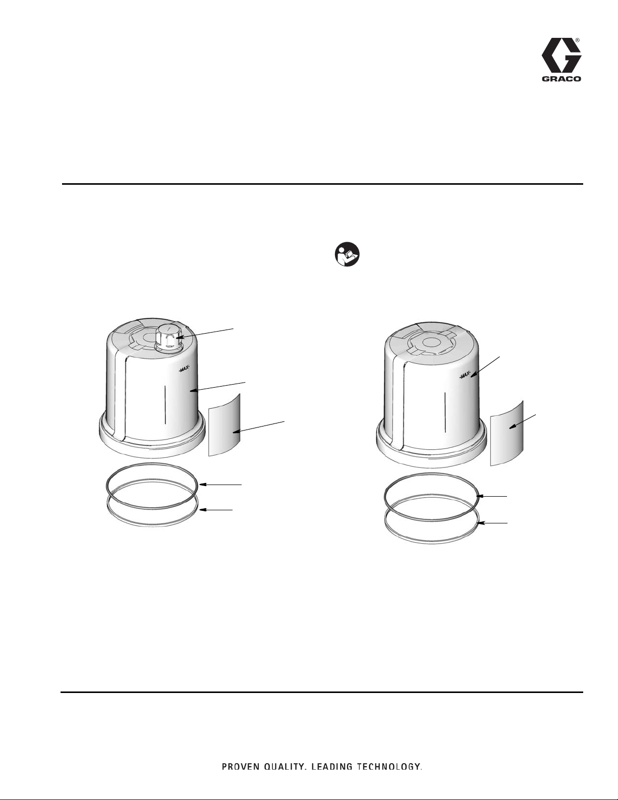
Kit Parts 571179, 571182
Ref. Description Qty
1 RESERVOIR 1
2 CAP, oil, fill 1
3 LABEL 1
4O-RING 1
5 O-RING, square 1
Kit Parts 571042, 571069, 571183
Ref. Description Qty
1O-RING 1
2 RESERVOIR 1
3 LABEL 1
4 O-RING, square 1
Page 2
Instructions
R
S
FP
FPS
Instructions
Pressure Relief
SKIN INJECTION HAZARD
High-pressure fluid from dispense device, hose leaks, or
ruptured components will pierce skin. This may look like
just a cut, but it is a serious injury that can result in amputation. Get immediate surgical treatment.
Follow Pressure Relief Procedure in this manual, when
you stop dispensing and before cleaning, checking, or
servicing equipment.
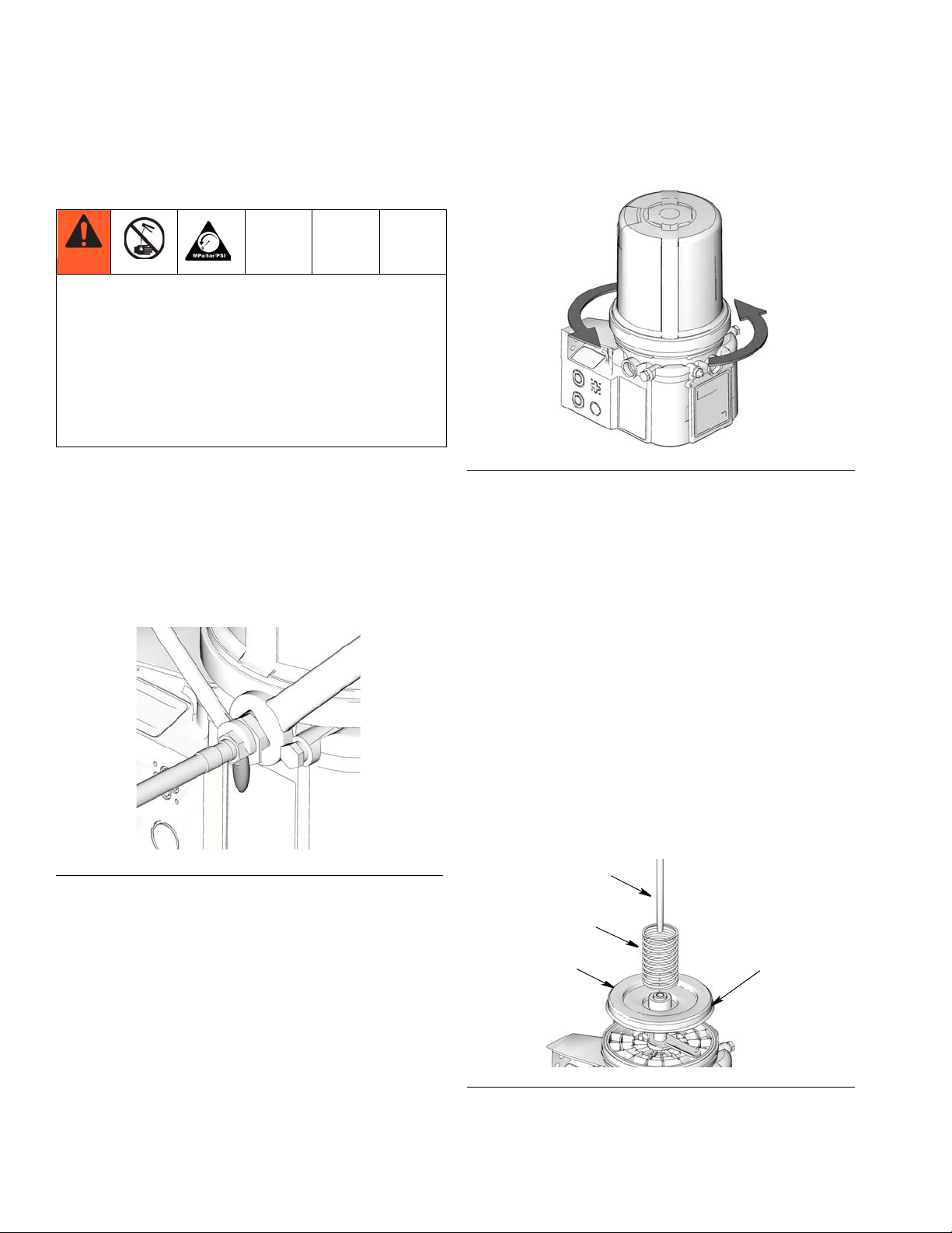
Relieve pressure in system by using two wrenches
working in opposite directions on pump element and
pump element fitting to only loosen fitting.
NOTE: When loosening pump element fitting, do NOT
loosen pump element. Loosening pump element will
change the output volume.
3. Use a strap wrench around reservoir to turn reservoir 1/4 turn counter-clockwise (F
FIG. 2
4. Remove reservoir from G3 base and discard reservoir according to local codes for proper disposal.
NOTE: If your unit includes a follower plate, remove any
parts noted in Step 1 of the Follower Plate Disassembly
section and keep those parts for reassembly.
IG. 2).
F
IG. 1
Disassembly
Reference numbers used in these instructions correspond to parts included in Kit and are provided on page
1. Parts identified with an alpha character are user provided or already installed components.
Reservoir Disassembly
1. Disconnect power source.
2. Relieve pressure using Pressure Relief Procedure
provided.
Follower Plate Disassembly
If your unit does not have a follower plate, continue
disassembly with O-Ring Disassembly instructions,
page 3.
1. Verify the following parts were removed with reservoir (F
IG. 3):
•Spring (S)
• Follower Pate (FP)
• Follower Plate Seal (FPS)
• Rod (R)
FIG. 3
2. Remove any parts still installed in the G3 base.
2 3A0534F
Page 3

Instructions
a
b
c
d
f
b
e
3. Be sure parts remaining in reservoir were removed
to reuse them for reassembly.
4. Examine follower plate seal referenced in Step 1 for
wear or damage. If it is damaged, it must be
replaced. Part No. 278139 is available from Graco.
Contact customer service to order this part or your
local Graco distributor.
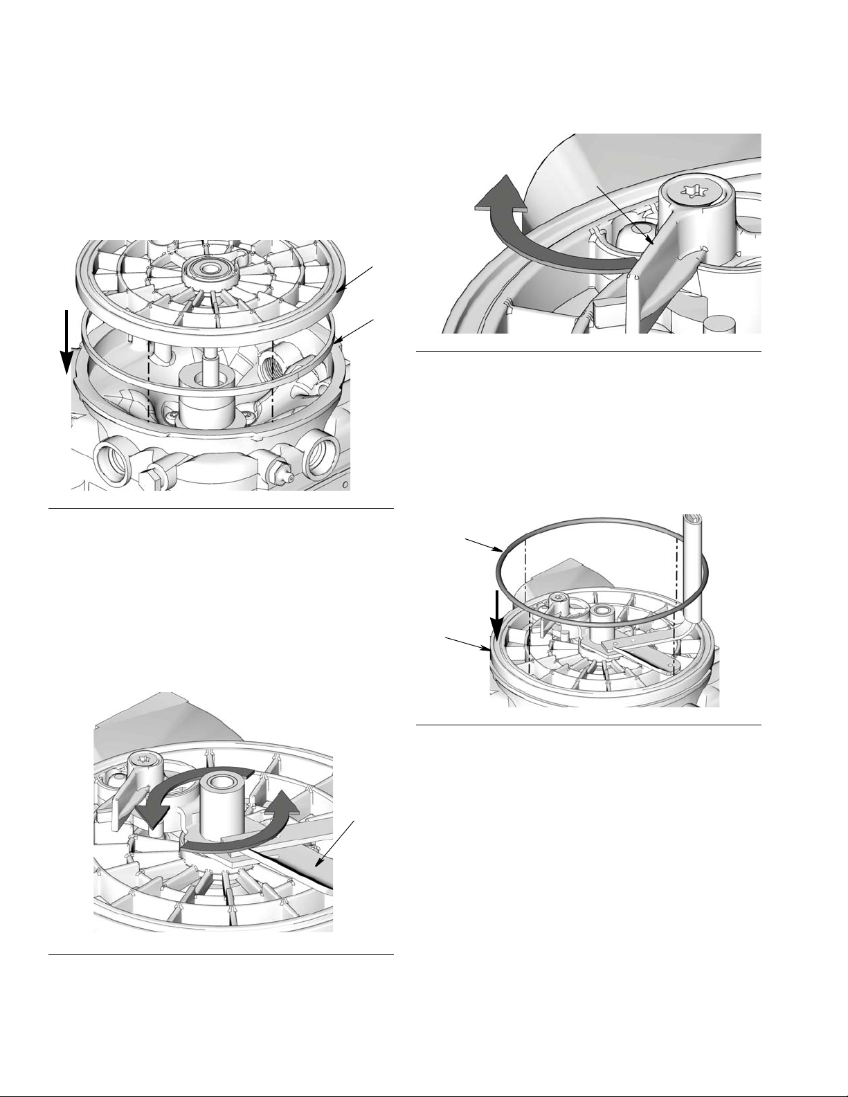
Upper O-Ring Disassembly
If o-ring (a) did not come out of the groove in ricer plate
(b) when reservoir was removed, remove and discard
o-ring according to local codes for proper disposal (F
4).
IG.
Lower O-Ring Disassembly Instructions
1. Perform all applicable previous disassembly instructions for reservoir, follower plate (if applicable) and
upper o-ring.
2. Turn paddle (c) clockwise to loosen and remove it
from G3 base (F
NOTE: For models that include a Low Level paddle
and/or follower plate only, be careful when removing
stirring paddle from G3 that bearing (f) does not fall
into the unit.
IG. 5).
FIG. 4
The lower o-ring is located beneath the ricer plate
(b). If replacing this o-ring, continue with Lower
O-Ring Disassembly instructions.
If lower o-ring is not replaced, begin Reassembly
FIG. 5
3. Remove ricer plate (b) from G3 base.
instructions starting on page 4.
FIG. 6
4. Remove o-ring (e) located under ricer plate (F
IG. 6).
3A0534F 3
Page 4
Instructions
b
1
c
d
b
1
Reassembly
Lower O-Ring Installation
1. Coat new o-ring (1) with grease (user supplied) and
install o-ring in bottom groove of ricer plate (b).
FIG. 9
4. Complete installation following instructions for Top
O-ring and Reservoir installation, page 4.
Top O-ring Installation
1. Coat new o-ring (1) with grease (user supplied).
FIG. 7
2. Replace ricer plate (b), aligning circular sections
with the round bosses in the base.
NOTE: It may be necessary to use a press to seat
the plate properly in the G3 base.
3. Reinstall paddle (c) by turning it counter-clockwise
till tight - hand tighten only (F
IG. 8).
2. Install o-ring in groove of ricer plate (b) (F
FIG. 10
IG. 10).
Follower Plate Installation
If your unit does not have a follower plate, continue
installation instructions with Top O-Ring Installation, page 5.
1. Verify low level paddle (d) is in full out position as
shown in F
IG. 9.
2. Install follower plate (FP) on stirring paddle (c). Be
FIG. 8
NOTE: If a low level paddle (d) is installed, to pre-
vent damage, hold low level paddle in its full out
position while installing stirring paddle (F
4 3A0534F
IG. 9).
sure the seal (FPS) is facing down (toward ricer
Page 5
Instructions
c
FP
S
R
FPS
f
2
g
h
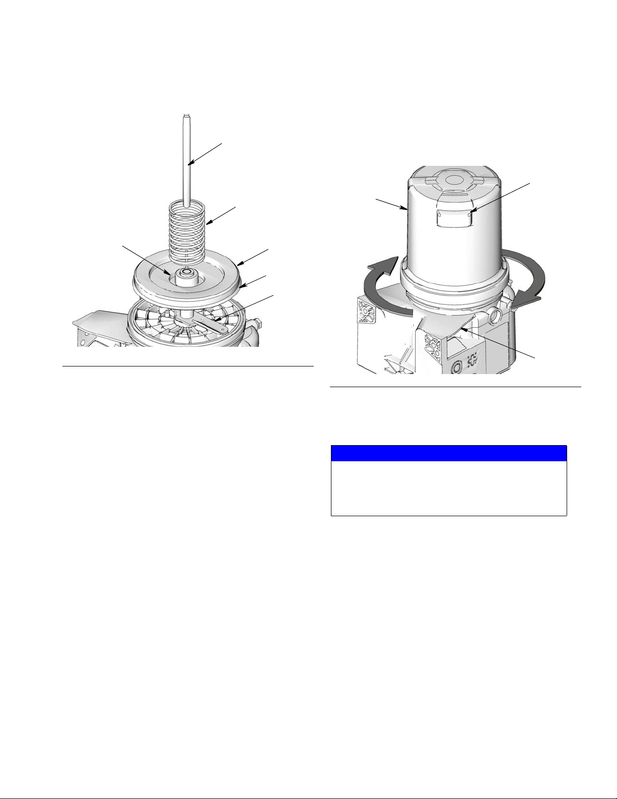
plate) as shown in FIG. 11.
FIG. 11
Reservoir Installation
1. Install new reservoir (2) with vent (g) facing toward
the rear left (h) of the G3 base. See F
rect orientation of these parts to ensure proper
installation.
IG. 12 for cor-
3. Install spring (S) into spring pocket (f).
4. Install Rod (R) into reservoir (2).
5. Slide rod (R) through center of spring (S) and follower plate (FP).
6. Seat spring in spring pocket in top of reservoir.
7. Compress spring to install reservoir. See Reservoir
Installation instructions.
FIG. 12
2. Position strap wrench over reservoir and use it to
turn reservoir 1/4 turn clockwise till reservoir will not
turn any farther (F
IG. 12).
NOTICE
Be careful when installing reservoir that o-ring is not
pinched. If the o-ring is not correctly installed,
grease could leak out of the bottom of the G3 reservoir.
3A0534F 5
Page 6

All written and visual data contained in this document reflects the latest product information available at the time of publication.
Graco reserves the right to make changes at any time without notice.
For patent information, see www.graco.com/patents
Original instructions. This manual contains English. MM 3A0534
Graco Headquarters: Minneapolis
International Offices: Belgium, China, Japan, Korea
GRACO INC. P.O. BOX 1441 MINNEAPOLIS, MN 55440-1441
Copyright 2010, Graco Inc. is registered to ISO 9001
www.graco.com
Revised April 2014
 Loading...