

Page 1
Instructions
G3 Pump Element
3A0533D
Replacement Kit
Instructions for adding/replacing a Pump Element used in G3 pump. For professional use
only.
Part No.: 571041
Important Safety Instructions
Read all warnings and instructions in this
manual and the G3 Pump instruction manual
included with your unit. Save these instructions.
2
ENG
4
2
3
4
1
1
Kit Parts 571041
Ref. Description Qty
1 PUMP, element 1
2 SPACER, stroke adjust 2
3 LABEL, safety (not shown) 1
4O-RING 1
Page 2
Instructions
Instructions
Pressure Relief
SKIN INJECTION HAZARD
High-pressure fluid from dispense device, hose leaks,
or ruptured components will pierce skin. This may look
like just a cut, but it is a serious injury that can result in
amputation. Get immediate surgical treatment.
Follow Pressure Relief Procedure in this manual,
when you stop dispensing and before cleaning, checking, or servicing equipment.
Relieve pressure in system by using two wrenches
working in opposite directions on pump element and
pump element fitting to only loosen fitting.
NOTE: When loosening pump element fitting, do NOT
loosen pump element. Loosening pump element will
change the output volume.
1. Disconnect power source.
2. Relieve pressure following Pressure Relief Procedure provided.
3. Disconnect anything installed to pump element such
as pressure relief valves, output union, or other fittings.
4. Use a wrench to loosen pump element (1) and completely remove pump element and spacers (2) from
G3 housing.
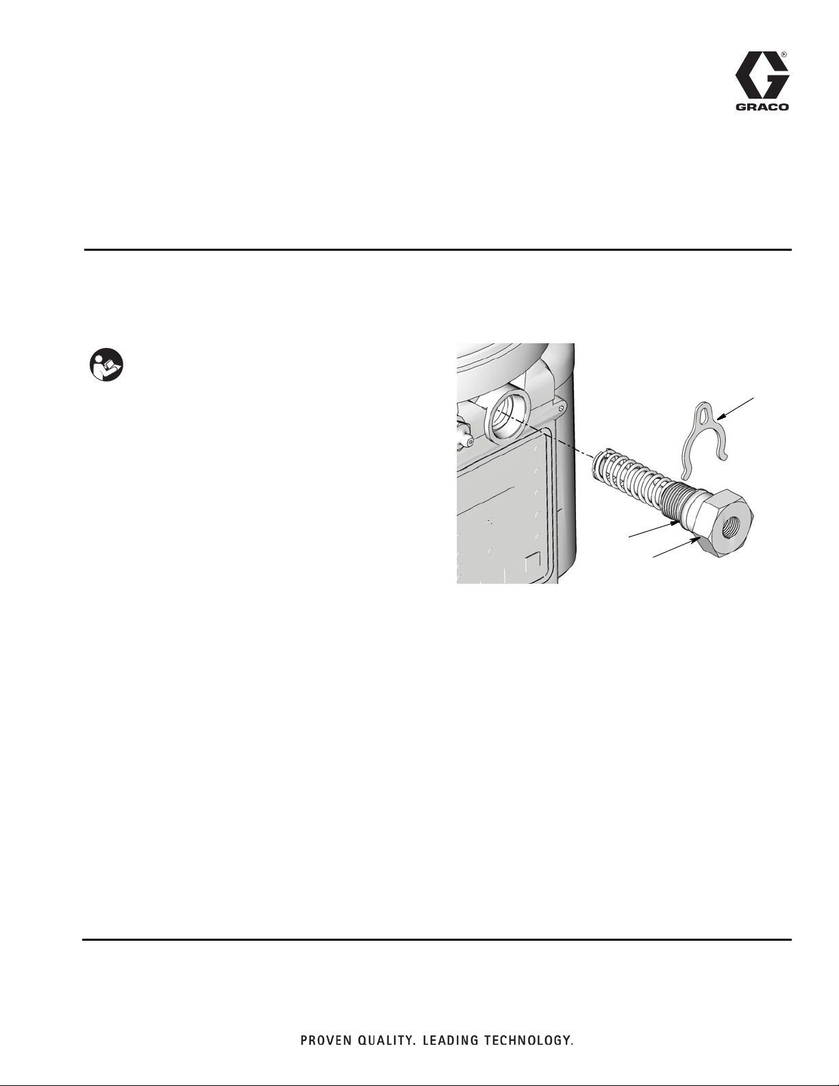
Make sure spring (a), retainer (b) and piston (c) are
removed with pump element (F
b
a
IG. 2).
2
1
4
FIG. 2
5. Discard these parts. They are not required for installation of the new pump element.
F
IG. 1
Disassembly
The following instructions are for removing a pump element currently installed in the G3 Pump.
Reference numbers used in these instructions correspond to parts included in Kit and are provided on page
1. Parts identified with an alpha character are user provided or already installed components.
2 3A0533D
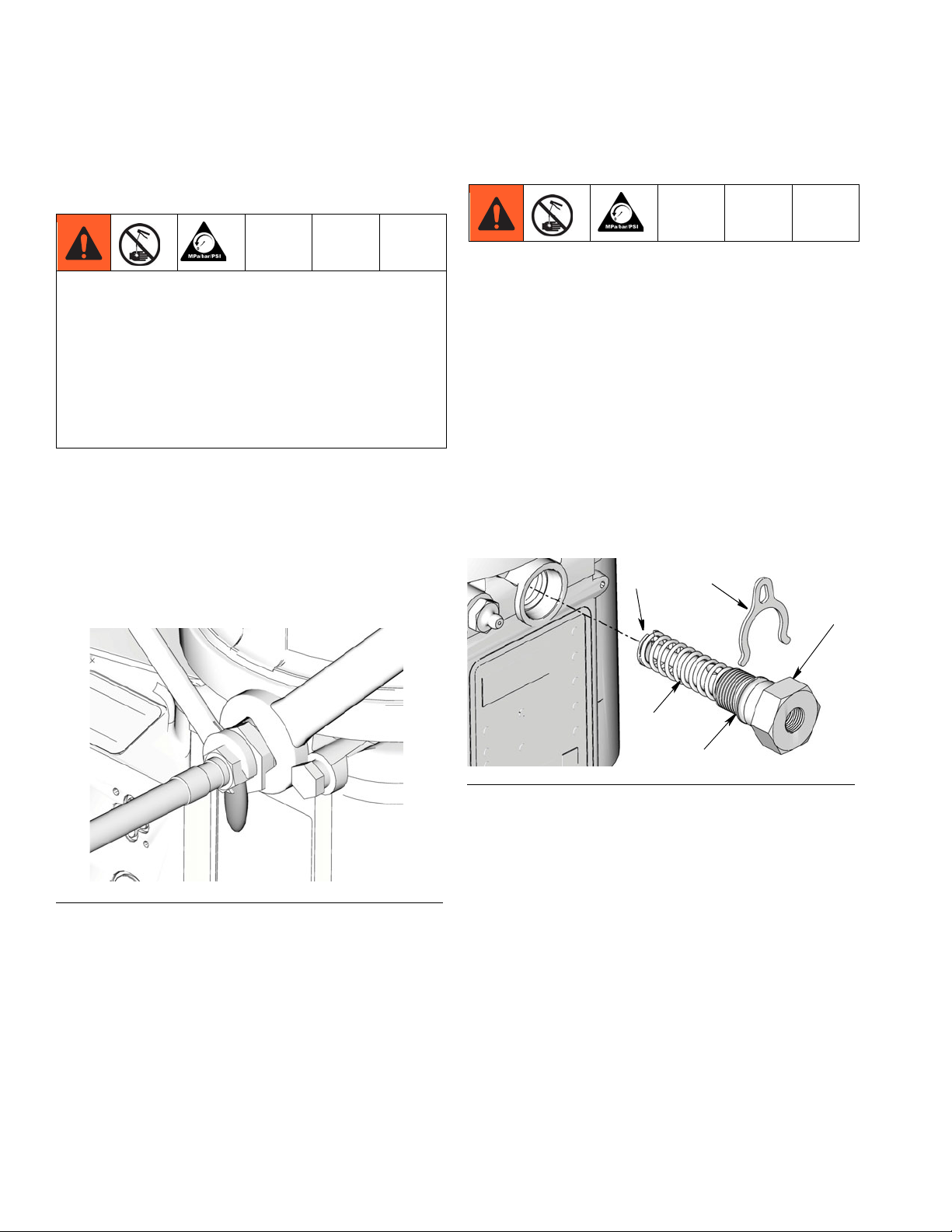
Installation
1. Examine new pump element (1) . Make sure spring
(a), retainer (b), o-ring (4) and piston are installed
(F
IG. 2).
2. Install stroke adjust spacers (2) (or no stroke adjust
spacers) as required for correct volume output.
• Discard old spacers you removed in Step 4.
Only use new, Graco supplied spacers included
in the kit to control output volume.
3. Slide pump element into G3 housing. Be careful not
to cross thread the pump element during installation.
Page 3

Instructions
4. Tighten pump element buy hand and then torque to
50 in. lbs (5.6 N•m) (F
F
IG. 3
IG. 3).
Adjusting Output Volume
NOTE:
• It may be necessary to repeat the outlet volume
setup procedure after the pump is operating to
re-adjust the volume of dispensed grease.
1. Use a wrench to turn pump element counter-clockwise to loosen.
2. If needed, remove or insert spacers to achieve
required pump output volume.
• Pump volume control is set using either no (0)
spacers, 1 or 2 spacers (F
IG. 4).
• Do not use more than 2 spacers on any pump
element.
Table 1: Output Volume
Output Volume / Minute
No. Spacers
cubic inches cubic cm
00.2474.0
10.182 3.0
20.1172.0
• The amount of dispensed volume can vary depending on external conditions such as lubricant temperature and back pressure from downstream
connections. Use the volume adjustments provided
in Table 1 as a starting point and adjust as necessary to ensure desired lubrication dispense.
F
IG. 4
3A0533D 3
Page 4

All written and visual data contained in this document reflects the latest product information available at the time of publication.
Graco reserves the right to make changes at any time without notice.
Original instructions. This manual contains English. MM 3A0533
Graco Headquarters: Minneapolis
International Offices: Belgium, China, Japan, Korea
GRACO INC. P.O. BOX 1441 MINNEAPOLIS, MN 55440-1441
Copyright 2010, Graco Inc. is registered to ISO 9001
www.graco.com
6/2010, Revised 1/2011
 Loading...