

Page 1

Instructions
5
1
1
2
3
5
4
6
G3 Pressure Relief with
Return to Reservoir
3A0525F
Installation Kit
Used to relieve unintended pressure rises in the system and return relieved contents back
to the reservoir. For professional use only.
Maximum Pressure: 3500 psi (241 bar, 24 MPa)
Part Nos.: 571028, 571071
Important Safety Instructions
Read all warnings and instructions in this
manual and the G3 Pump instruction manual
included with your unit. Save these instructions.
EN
Kit Parts
Qty
Ref. Description
1 WASHER, sealing 2 2
2 FITTING, banjo, 1/4 npt 1 1
3 BOLT, banjo, 1/4 npt 1 0
BOLT, banjo, 1/4 bspp 0 1
4 TUBE, nylon, round 1 1
5 FITTING, 90°, elbow 2 2
6 VALVE, pressure relief 1 1
See Pressure Relief Valves, page 2
571028 571071
Page 2

Instructions
a
ti15644
locking nut
ti14711
a
ti15468
Instructions
Pressure Relief Valves
The Pressure Relief Valve included in this kit can
only be used on the G3 Pump. It is not intended for
use with any other products.
The pressure relief valve uses a
pressure adjustment screw (a) to
set the pressure release point. It
is not intended as a way to
relieve pressure during normal operation but as a protec-
tive measure in the event there is
an unintended pressure increase
in the system.
NOTE:
• Do not use this pressure relief valve as a means
of relieving pressure in day-to-day, normal cycle
operation. Use the pressure relief procedure
described in the next section of this manual to
relieve pressure during normal cycle operation.
• Factory set to 3000 psi (207 bar, 20.7 MPa).
The pressure adjustment screw (a) will require periodic
adjustments. Whenever the valve is set/adjusted (after
the set point is found) it is important to ensure that the
valve is not bottomed out and there is at least 1/2 turn of
adjustment remaining. This is determined by turning the
screw (a) 1/2 turn and then back turning it out again.
NOTE: Turning adjustment screw (a) clockwise
increases pressure.
Relieve pressure in system by using two wrenches
working in opposite directions on pump element and
pump element fitting to only loosen fitting.
NOTE: When loosening pump element fitting, do NOT
loosen pump element. Loosening pump element will
change the output volume.
FIG. 1
Installation
Reference numbers used in these instructions correspond to parts included in Kit and are provided on page
1. Parts identified with an alpha character are user provided or already installed components.
1. Disconnect power source.
2. If unit has already been in service, relieve pressure,
page 2.
Pressure Relief Procedure
SKIN INJECTION HAZARD
High-pressure fluid from dispense device, hose leaks, or
ruptured components will pierce skin. This may look like
just a cut, but it is a serious injury that can result in amputation. Get immediate surgical treatment.
Follow Pressure Relief Procedure in this manual, when
you stop dispensing and before cleaning, checking, or
servicing equipment.
2 3A0525F
3. Use a wrench to loosen plug (a) from return location. Remove plug from port (F
FIG. 2
IG. 2).
Page 3

Instructions
b
5
ti15469
6
b
2
1
1
3
5
ti15470
3
d
ti15471
ti15499
4. Apply thread sealant (user supplied) to threads (b)
of one of the 90° tube elbow fittings (5).
5. Install 90° elbow fitting (5) in open port.
FIG. 3
6. Wrench tighten then torque to 50 in. lbs (5.6 N•m).
7. Apply thread sealant (user supplied) to threads (b)
of pressure relief valve (6) (F
IG. 4).
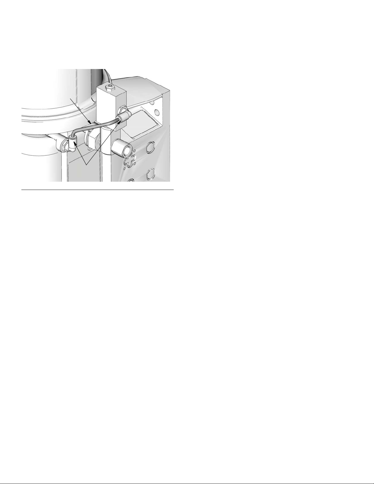
11. Install banjo bolt (3) into pump element (d) (F
IG. 5).
NOTE: Relieve valve orientation may vary depending on
your specific installation.
FIG. 5
12. Use two wrenches to tighten the banjo fitting (3).
Place one wrench on the pump element (d) and the
second wrench over the end of the banjo bolt (3).
ONLY tighten the banjo bolt (3) while holding the
pump element (d) securely in place. Torque banjo
bolt (3) to 35 ft. lbs (45.7 N•m). Take care to not
over-tighten (F
IG. 6).
FIG. 4
8. Install pressure relief valve (6) into banjo fitting (2).
Wrench tighten (F
9. Install one washer (1) over end banjo bolt (3). Then
install banjo fitting (2) onto banjo bolt (3). Install second washer (1) over end of banjo bolt. (F
10. Apply thread sealant (user supplied) to threads (b)
of second 90° tube elbow fitting (5). Install fitting in
pressure relief valve. Wrench tighten.
IG. 4).
IG. 6
F
IG. 4).
13. Cut supply tube (4) to desired length.
NOTE: Tube length must be long enough to prevent
tube from kinking.
3A0525F 3
Page 4
14. Install supply tube between the two elbow fittings (5)
4
5
ti15471
(F
IG. 7). Push in to seat.
FIG. 7
All written and visual data contained in this document reflects the latest product information available at the time of publication.
Graco reserves the right to make changes at any time without notice.
Original instructions. This manual contains English. MM 3A0525
Graco Headquarters: Minneapolis
International Offices: Belgium, China, Japan, Korea
GRACO INC. P.O. BOX 1441 MINNEAPOLIS, MN 55440-1441
Copyright 2010, Graco Inc. is registered to ISO 9001
www.graco.com
Revised November 2014
 Loading...