

Page 1
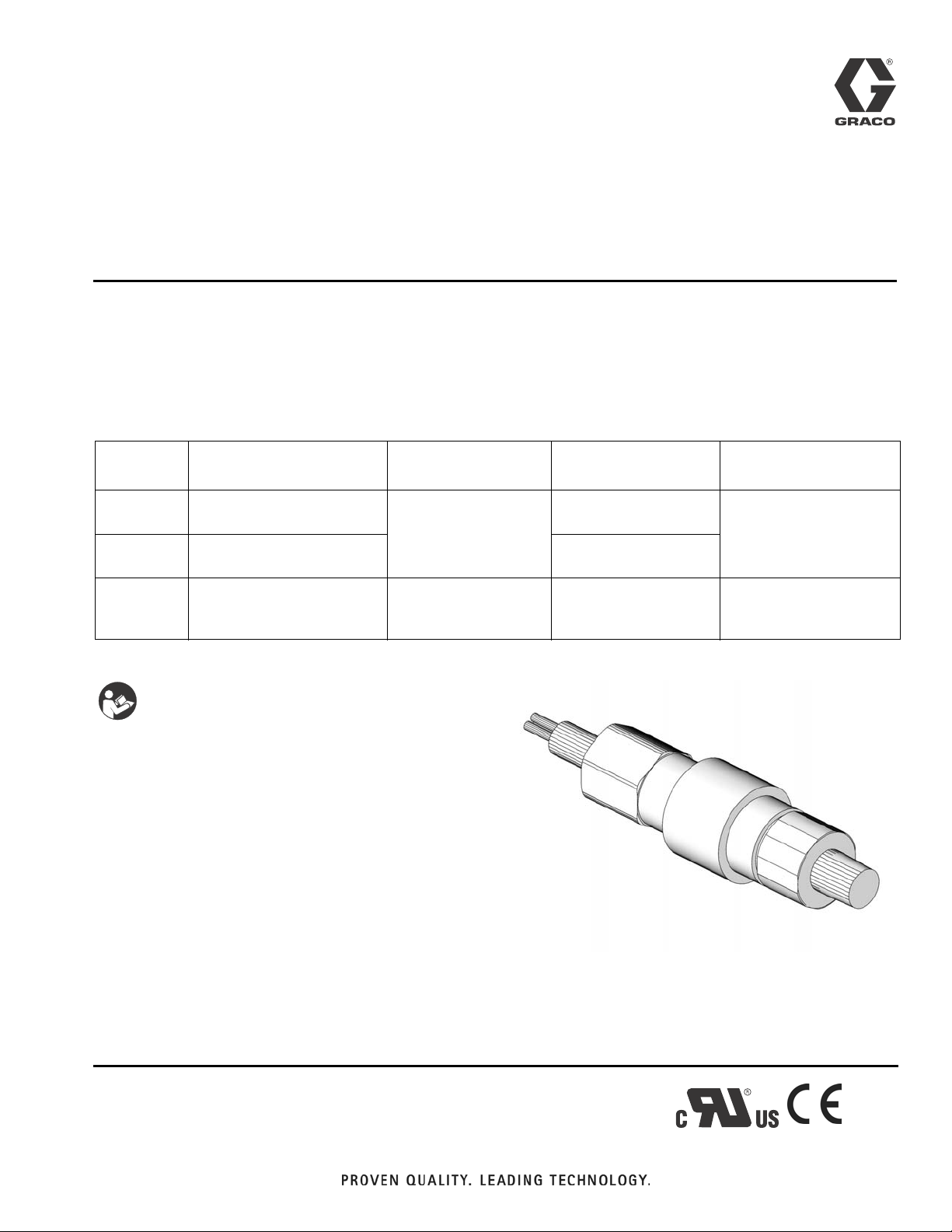
Instructions
3A0471B
Pressure Switch
Bulletin 15521
Moisture-resistant single control pressure switches used to detect pressure changes.
Not approved for use in European explosive atmospheres.
Models:
Model No. Description
557828 Stainless steel piston and
Buna-N o-ring sensor
557829 Stainless steel piston and
Buna-N o-ring sensor
557830 Buna-N, diaphragm sen-
sor
Important Safety Instructions
Read all warnings and instructions in this manual.
Save these instructions.
Pressure Range
Adjustment
400 - 4700 psi
(2.75 MPa, 27.57 bar
- 32.4 MPa, 324 bar)
10 - 150 psi
(0.07 MPa, 0.69 bar -
1.03 MPa, 10 bar)
Factory Pressure
Preset Max Pressure
750 psi rising
(5.17 Mpa, 51.7 bar)
1150 psi rising
(7.93 MPa, 79.28 bar)
50 psi rising
(0.34 MPa, 3.44 bar)
4700 psi
(32.4 MPa, 324 bar)
1500 psi
(10.3 MPa, 103.4 bar)
ENG
Tools Needed:
• 1-1/16 inch open end wrench
• flat blade screwdriver
Page 2
Warnings
Warnings
The following warnings are for the setup, use, grounding, maintenance, and repair of this equipment. The exclamation point symbol alerts you to a general warning and the hazard symbols refer to procedure-specific risks. When
these symbols appear in the body of this manual, refer back to these Warnings. Product-specific hazard symbols and
warnings not covered in this section may appear throughout the body of this manual where applicable.
WARNING
ELECTRIC SHOCK HAZARD
This equipment must be grounded. Improper grounding, setup, or usage of the system can cause electric
shock.
• Turn off and disconnect power at main switch before disconnecting any cables and before servicing
equipment.
• Connect only to grounded power source.
• All electrical wiring must be done by a qualified electrician and comply with all local codes and
regulations.
SKIN INJECTION HAZARD
High-pressure fluid from dispense device, hose leaks, or ruptured components will pierce skin. This may
look like just a cut, but it is a serious injury that can result in amputation. Get immediate surgical treat-
ment.
• Do not point dispense device at anyone or at any part of the body.
• Do not put your hand over the fluid outlet.
• Do not stop or deflect leaks with your hand, body, glove, or rag.
• Follow Pressure Relief Procedure in this manual, when you stop dispensing and before cleaning,
checking, or servicing equipment.
• Tighten all fluid connections before operating the equipment.
• Check hoses and couplings daily. Replace worn or damaged parts immediately.
Pressure Relief Procedure
Pressure Relief
Relieve pressure in system following procedure recom-
mended for your operating system or pump.
2 3A0471B
Page 3

Warnings
Installation
• A high or low limit switch is necessary for application where a runaway condition could result.
• The adjustable range must be selected so that
incorrect, inadvertent setting at any range point
cannot result.
NOTICE
• Electrical ratings must not be exceeded. Overload on a switch can cause switch to fail on the
first cycle.
• Never exceed pressure limits. Unit can be operated up to maximum pressure on a limited basis
(i.e., set-up, testing) but continuous operation
must be restricted to the designated adjustable
range. Excessive cycling at maximum pressure
limits could reduce sensor life.
4. Mount using pressure connection: always use a
wrench on pressure connection wrench flats.
5. Attach conduit connection, hold electrical connection steady with wrench on hex, then thread in conduit.
6. Test unit before use.
Adjustments
1. Disconnect power to switch.
2. Connect switch to a calibrated pressure source.
3. Slide adjustment cover (a) (open) toward cable. It
may be necessary to twist cover to overcome friction
(F
IG. 1).
1. Locate unit where shock, vibration and ambient temperature fluctuations are minimal. Do not mount in
ambient temperature areas exceeding 160°F
(71°C).
• Unit may be mounted in any position. However,
if installation location results in frequent exposure to liquid it is recommended that the unit be
mounted vertically with the pressure connection
down.
• If the unit is to be set after mounting, raise
adjustment cover, then thread in pressure connection until snug. Verify adjustment opening is
accessible.
2. Cut pressure switch cord to desired length.
3. Strip back insulation (see Table 1 for terminals and
corresponding color).
Table 1 - Terminal Colors
Terminals Color
a
c
FIG. 1
4. Connect power to terminals or leads.
5. With the cable (b) facing up, insert the blade of a flat
screwdriver into the adjustment slot (c) (F
• Turn the dial to the left to increase the setpoint.
• Turn the dial to the right to decrease the set-
point.
b
IG. 1).
N.O. Red
N.C. Black
Com White
3A0471B 3
Page 4

Warnings
6. After setting is complete, slide adjustment collar (a)
(closed), over adjustment chamber opening (F
IG. 2).
a
FIG. 2
7. Recheck set point and install switch according to
Installation instructions.
Technical Data and Dimensions
Ambient Temperature Range 0° to 160°F (-17° to 70°C
Maximum Media Temperature 200°F (93°C)
Termination Type 1/2 NPT
Electrical Ratings
@125 VAC & 250 VAC, 1/4 hp* 5A resistive / 5A inductive
(75% power factor)
@30 VDC* 5A resistive / 3 A inductive
@125VDC* 0.5A resistive / 0.25 inductive
*gold clad silver contacts for loads down to 5mA at 6VDC,
2mA at 12 VDC, 1mA at 24 VDC
1.25 in. (31.8 mm)
Factory Seal
3 Wire Cable
5 ft. long
4.19 in. (106.4 mm)
1/4 in. NPT (male)
4 3A0471B
Page 5

Notes
Notes
3A0471B 5
Page 6

Graco Standard Warranty
Graco warrants all equipment referenced in this document which is manufactured by Graco and bearing its name to be free from defects in
material and workmanship on the date of sale to the original purchaser for use. With the exception of any special, extended, or limited warranty
published by Graco, Graco will, for a period of twelve months from the date of sale, repair or replace any part of the equipment determined by
Graco to be defective. This warranty applies only when the equipment is installed, operated and maintained in accordance with Graco’s written
recommendations.
This warranty does not cover, and Graco shall not be liable for general wear and tear, or any malfunction, damage or wear caused by faulty
installation, misapplication, abrasion, corrosion, inadequate or improper maintenance, negligence, accident, tampering, or substitution of
non-Graco component parts. Nor shall Graco be liable for malfunction, damage or wear caused by the incompatibility of Graco equipment with
structures, accessories, equipment or materials not supplied by Graco, or the improper design, manufacture, installation, operation or
maintenance of structures, accessories, equipment or materials not supplied by Graco.
This warranty is conditioned upon the prepaid return of the equipment claimed to be defective to an authorized Graco distributor for verification of
the claimed defect. If the claimed defect is verified, Graco will repair or replace free of charge any defective parts. The equipment will be returned
to the original purchaser transportation prepaid. If inspection of the equipment does not disclose any defect in material or workmanship, repairs will
be made at a reasonable charge, which charges may include the costs of parts, labor, and transportation.
THIS WARRANTY IS EXCLUSIVE, AND IS IN LIEU OF ANY OTHER WARRANTIES, EXPRESS OR IMPLIED, INCLUDING BUT NOT LIMITED
TO WARRANTY OF MERCHANTABILITY OR WARRANTY OF FITNESS FOR A PARTICULAR PURPOSE.
Graco’s sole obligation and buyer’s sole remedy for any breach of warranty shall be as set forth above. The buyer agrees that no other remedy
(including, but not limited to, incidental or consequential damages for lost profits, lost sales, injury to person or property, or any other incidental or
consequential loss) shall be available. Any action for breach of warranty must be brought within two (2) years of the date of sale.
GRACO MAKES NO WARRANTY, AND DISCLAIMS ALL IMPLIED WARRANTIES OF MERCHANTABILITY AND FITNESS FOR A
PARTICULAR PURPOSE, IN CONNECTION WITH ACCESSORIES, EQUIPMENT, MATERIALS OR COMPONENTS SOLD BUT NOT
MANUFACTURED BY GRACO. These items sold, but not manufactured by Graco (such as electric motors, switches, hose, etc.), are subject to
the warranty, if any, of their manufacturer. Graco will provide purchaser with reasonable assistance in making any claim for breach of these
warranties.
In no event will Graco be liable for indirect, incidental, special or consequential damages resulting from Graco supplying equipment hereunder, or
the furnishing, performance, or use of any products or other goods sold hereto, whether due to a breach of contract, breach of warranty, the
negligence of Graco, or otherwise.
FOR GRACO CANADA CUSTOMERS
The Parties acknowledge that they have required that the present document, as well as all documents, notices and legal proceedings entered into,
given or instituted pursuant hereto or relating directly or indirectly hereto, be drawn up in English. Les parties reconnaissent avoir convenu que la
rédaction du présente document sera en Anglais, ainsi que tous documents, avis et procédures judiciaires exécutés, donnés ou intentés, à la suite
de ou en rapport, directement ou indirectement, avec les procédures concernées.
Graco Information
TO PLACE AN ORDER, contact your Graco distributor or call to identify the nearest distributor.
Phone: 612-623-6928 or Toll Free: 1-800-533-9655, Fax: 612-378-3590
All written and visual data contained in this document reflects the latest product information available at the time of publication.
Graco reserves the right to make changes at any time without notice.
Original Insructions. This manual contains English. MM 3A471
Graco Headquarters: Minneapolis
International Offices: Belgium, China, Japan, Korea
GRACO INC. P.O. BOX 1441 MINNEAPOLIS, MN 55440-1441
Copyright 2010, Graco Inc. is registered to ISO 9001
www.graco.com
4/2010, revised 8/2010
 Loading...