

Page 1
Repair
™
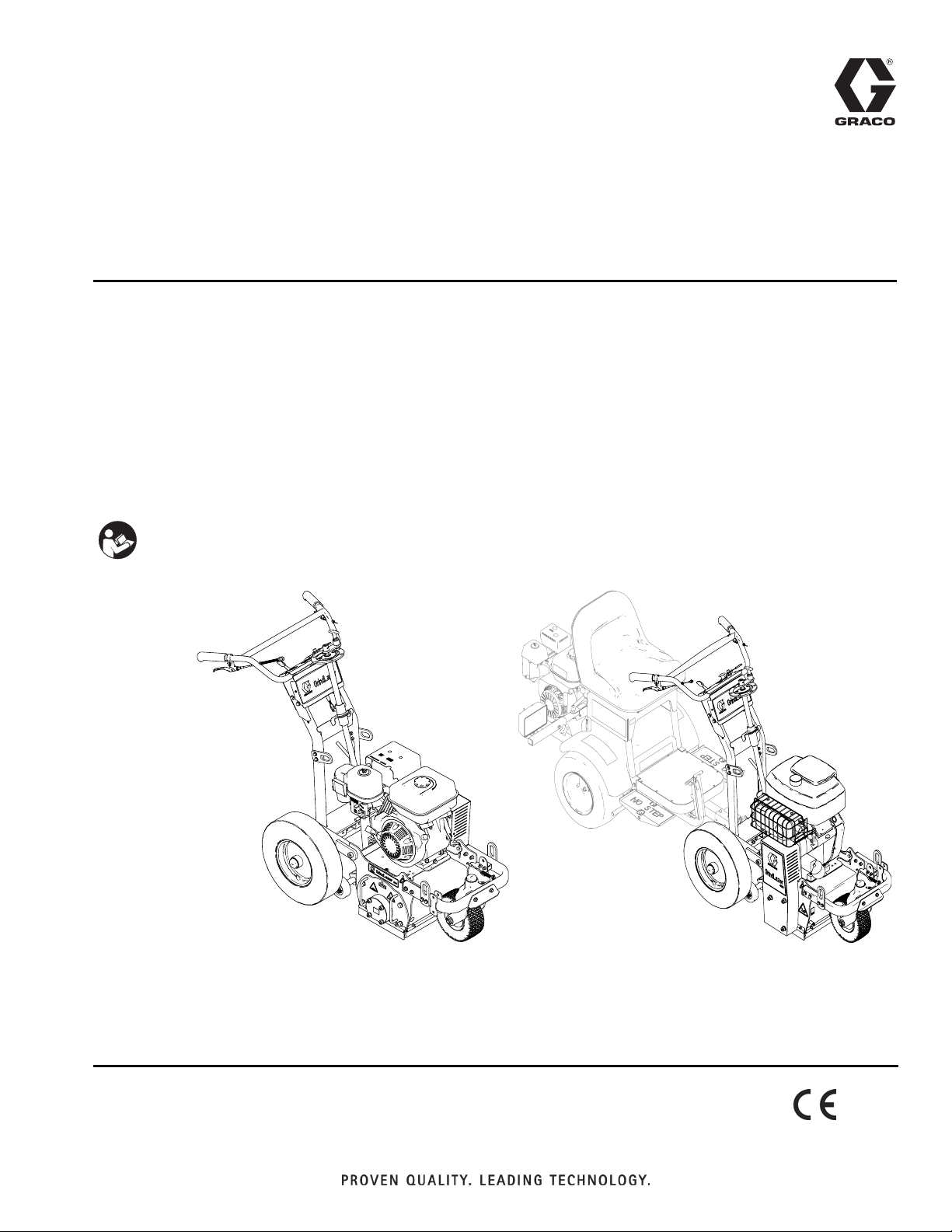
GrindLazer
Patents Pending
- Designed to grind flat, horizontal concrete or asphalt surfaces -
- For removal of materials from concrete and asphalt surfaces -
- Professional outdoor use only -
Model 571002 - Forward cut
GrindLazer 270 (270 cc / 9 hp)
Model 571003 - Forward cut
GrindLazer 390 (390 cc / 13 hp)
Model 571004 - Reverse up-cut (Must be used with LineDriver
GrindLazer 480 (480 cc / 16 hp)
IMPORTANT SAFETY INSTRUCTIONS
Read all warnings and instructions in this
manual. Save these instructions.
3A0102C
EN
™
)
Related Manuals:
Operation - 3A0101
Parts - 3A0103
ti14752b
GrindLazer 270 and 390
(Drums, cutters, and LineDriver
GrindLazer 480
™
sold separately)
ti14763a
Page 2

Table of Contents
Table of Contents
Warnings . . . . . . . . . . . . . . . . . . . . . . . . . . . . . . . . . 3
Component Identification . . . . . . . . . . . . . . . . . . . . 5
Drum Replacement . . . . . . . . . . . . . . . . . . . . . . . . . 6
Cutter Replacement . . . . . . . . . . . . . . . . . . . . . . . . . 7
Belt Replacement . . . . . . . . . . . . . . . . . . . . . . . . . . 9
Clutch Replacement . . . . . . . . . . . . . . . . . . . . . . . 11
Pulley Replacement . . . . . . . . . . . . . . . . . . . . . . . . 12
Brush Replacement . . . . . . . . . . . . . . . . . . . . . . . . 13
Drive Bearing Assembly Replacement . . . . . . . . 14
Door Bearing Assembly Removal . . . . . . . . . . . 14
Door Bearing Assembly Installation . . . . . . . . . 14
Drive Bearing Assembly Removal . . . . . . . . . . . 15
Drive Bearing Assembly Installation . . . . . . . . . 16
Sheave Installation . . . . . . . . . . . . . . . . . . . . . . 16
Cutter Stacking Recommendations . . . . . . . . . . . 17
6 in. (15 cm) Coarse Cut Flail Cutters
(Double Space) . . . . . . . . . . . . . . . . . . . . . . 17
8 in. (20 cm) Coarse Cut Flail Cutters
(Double Space) . . . . . . . . . . . . . . . . . . . . . . 18
10 in. (25 cm) Coarse Cut Flail Cutters
(Double Space) . . . . . . . . . . . . . . . . . . . . . . 19
6 in. (15 cm) General Cut Flail Cutters
(Single Space) . . . . . . . . . . . . . . . . . . . . . . . 20
8 in. (20 cm) General Cut Flail Cutters
(Single Space) . . . . . . . . . . . . . . . . . . . . . . . 21
10 in. (25 cm) General Cut Flail Cutters
(Single Space) . . . . . . . . . . . . . . . . . . . . . . . 22
6 in. (15 cm) Fine Cut Flail Cutters . . . . . . . . . . . 23
8 in. (20 cm) Fine Cut Flail Cutters . . . . . . . . . . . 24
10 in. (25 cm) Fine Cut Flail Cutters. . . . . . . . . . 25
6 in. (15 cm) Cut Carbide Millers . . . . . . . . . . . . 26
8 in. (20 cm) Cut Carbide Millers . . . . . . . . . . . . 27
10 in. (25 cm) Cut Carbide Millers . . . . . . . . . . . 28
Diamond Blades . . . . . . . . . . . . . . . . . . . . . . . . 29
Troubleshooting . . . . . . . . . . . . . . . . . . . . . . . . . . . 30
Technical Data . . . . . . . . . . . . . . . . . . . . . . . . . . . . 31
Graco Standard Warranty . . . . . . . . . . . . . . . . . . . 32
2 3A0102C
Page 3

Warnings
Warnings
The following warnings are for the setup, use, grounding, maintenance, and repair of this equipment. The
exclamation point symbol alerts you to a general warning and the hazard symbol refers to procedure-specific risk.
Refer back to these warnings. Additional, product-specific warnings may be found throughout the body of this manual
where applicable.
WARNING
DUST AND DEBRIS HAZARD
Use of this equipment to grind concrete and other paving materials can result in the release of potentially
harmful dust or chemicals from the materials.
• For use only by sophisticated users familiar with applicable governmental safety and industrial
hygiene regulations.
• Use equipment only in a well-ventilated area.
• Wear a properly fit-tested and government approved respirator suitable for the dust conditions.
EQUIPMENT MISUSE HAZARD
Misuse can cause death or serious injury.
• Do not operate the unit when fatigued or under the influence of drugs or alcohol.
• Do not leave the work area while equipment is energized. Turn off all equipment when equipment is
not in use.
• Check equipment daily. Repair or replace worn or damaged parts immediately with genuine manufacturer’s replacement parts only.
• Do not alter or modify equipment.
• Use equipment only for its intended purpose. Call your distributor for information.
• Keep children and animals away from work area.
• Comply with all applicable safety regulations.
• Maintain a safe operating distance from other people in the work area.
• Avoid any pipes, columns, openings, or any other objects protruding from work surface.
MOVING VEHICLE HAZARD
Careless and reckless behavior causes accidents. Falling from vehicle, running into people or object, or
being struck by other vehicles may result in serious injury or death.
• Do not step on forward/reverse pedals.
• Make turns slowly. Do not make turns greater than 45°.
• Loss of traction may occur going downhill. Do not operate on slopes greater than 15°.
• Do not carry passengers.
• Do not tow.
• Use with line striping equipment only.
• Use appropriate traffic control in all traffic areas. Refer to Manual on Uniform Traffic Control Devices
(MUTCD), U.S. Department of Transportation, Federal Highway Administration or local highway and
transportation regulations.
MOVING PARTS HAZARD
Moving parts can pinch or amputate fingers and other body parts.
• Keep clear of moving parts.
• Do not operate equipment with protective guards or covers removed.
• Before checking, moving, or servicing equipment, disable power supply.
BURN HAZARD
Equipment surfaces that are heated can become very hot during operation. To avoid severe burns, do
not touch hot equipment. Wait until equipment has cooled completely.
3A0102C 3
Page 4

Warnings
WARNING
FIRE AND EXPLOSION HAZARD
Flammable fumes, such as solvent and paint fumes, in work area can ignite or explode. To help prevent
fire and explosion:
• Use equipment only in well ventilated area.
• Do not fill fuel tank while engine is running or hot; shut off engine and let it cool. Fuel is flammable
and can ignite or explode if spilled on hot surface.
• Keep work area free of debris, including solvent, rags and gasoline.
• Keep a fire extinguisher in work area.
CARBON MONOXIDE HAZARD
Exhaust contains poisonous carbon monoxide, which is colorless and odorless. Breathing carbon
monoxide can cause death. Do not operate in an enclosed area.
PERSONAL PROTECTIVE EQUIPMENT
You must wear appropriate protective equipment when operating, servicing, or when in the operating
area of the equipment to help protect you from serious injury, including eye injury, inhalation of dust or
chemicals, burns, and hearing loss. This equipment includes but is not limited to:
• Protective eyewear
• Protective shoes
•Gloves
• Hearing protection
• Properly fit-tested and government approved respirator suitable for the dust conditions
4 3A0102C
Page 5
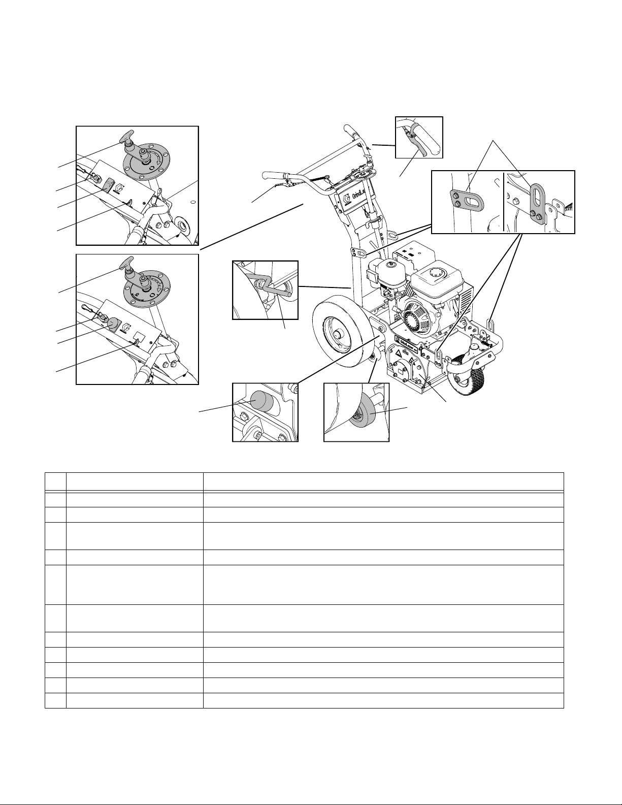
Component Identification
270 and 390 Models
D
C
B
A
D
E
Component Identification
N
F
C
B
A
480 Models
M
Component Description
A Engine Throttle Lever Adjusts engine speed.
B Engine Stop Switch Supplies power to Engine
C Emergency Shut-Off Clamps onto the operator and shuts engine off if cord is disconnected during
operation.
D Drum Adjustment Dial Raises and lowers cutting drum.
E Drum Engage Lever When lever is engaged, handle bars can be pushed down to raise the cutting
drum off of surface and locked into UP position. Once drum is locked in UP
position, GrindLazer can be moved around without drum touching surface.
F Front Wheel Lock Lever Front wheel is usually locked to guide GrindLazer in a straight line. When lever
is engaged, front wheel becomes unlocked and is allowed to turn freely.
G Rear Wheel Parking Brake Prevents rear wheel from moving.
H Drum Access Panel Removable plate that allows access to replace cutting drum.
K Depth Control Wheels Sets depth of drum cut
M Vacuum Port Port to attach vacuum to reduce dust and debris during operation.
N Lift Points Reinforced points used for lifting GrindLazer during transportation or repair.
G
ti14753b
K
H
3A0102C 5
Page 6
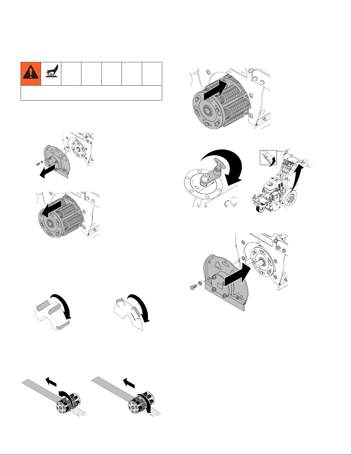
Drum Replacement
Drum Replacement
Avoid touching or handling drum after use until it has
completely cooled.
Removal
1. Slide replacement drum onto hex shaft.
1. Remove four bolts and Drum Access Panel (H).
ti14767b
2. Slide drum off of hex shaft.
ti14765a
Installation
NOTE: Carbide Flail Cutter drums do not require
specific orientation or direction. Carbide Millers and
Diamond Blades are directional. They should be stacked
so that the arrows on the Millers and Blades face the
same direction as the rotation of the drum.
ti14766a
2. Lower Drum Adjustment Dial (D) and pull Drum
Engage Lever (E) so drum rests on ground.
ti14756a
ti14755a
3. Replace Drum Access Panel (H) and tighten four
bolts to 27-30 ft-lb (37-41 N•m).
ti14764b
Carbide Miller
Diamond Blade
270 and 390 models are designed for “forward cut”
grinding (the drum rotates in the same direction that it
travels). 480 models are design for “reverse (up cut)”
grinding (the drum rotates in the opposite direction that
it travels).
ti15137a
Forward Cut (270/390 Models)
6 3A0102C
ti15138a
Reverse (up cut) 480 Models
Page 7
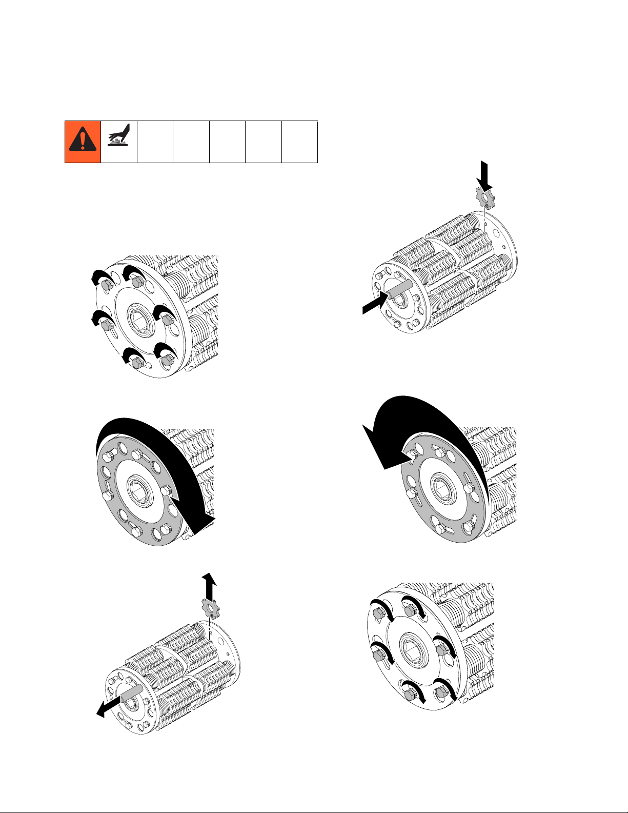
Cutter Replacement
Removal (Carbide Flail/Carbide Miller)
1. Remove drum (see Drum Replacement, page 6).
2. Loosen six bolts on each side of drum (do not
remove bolts).
Cutter Replacement
Installation (Carbide Flail/Carbide Miller)
1. Replace cutters and washers (see Cutter Stacking
Recommendations, pages 17 - 29).
ti15063a
ti15065a
3. Rotate plates on each side of drum so rods are
exposed.
ti15080a
4. Push rod out and remove cutters.
NOTE: Cutters must be centered on drum for best
performance.
2. Rotate plates on each side of drum to cover rods.
ti15079a
3. Tighten six bolts on each side of drum to 125-175
in-lb (14-20 N•m).
ti15082a
ti15075a
4. Install drum (see Drum Replacement, page 6).
3A0102C 7
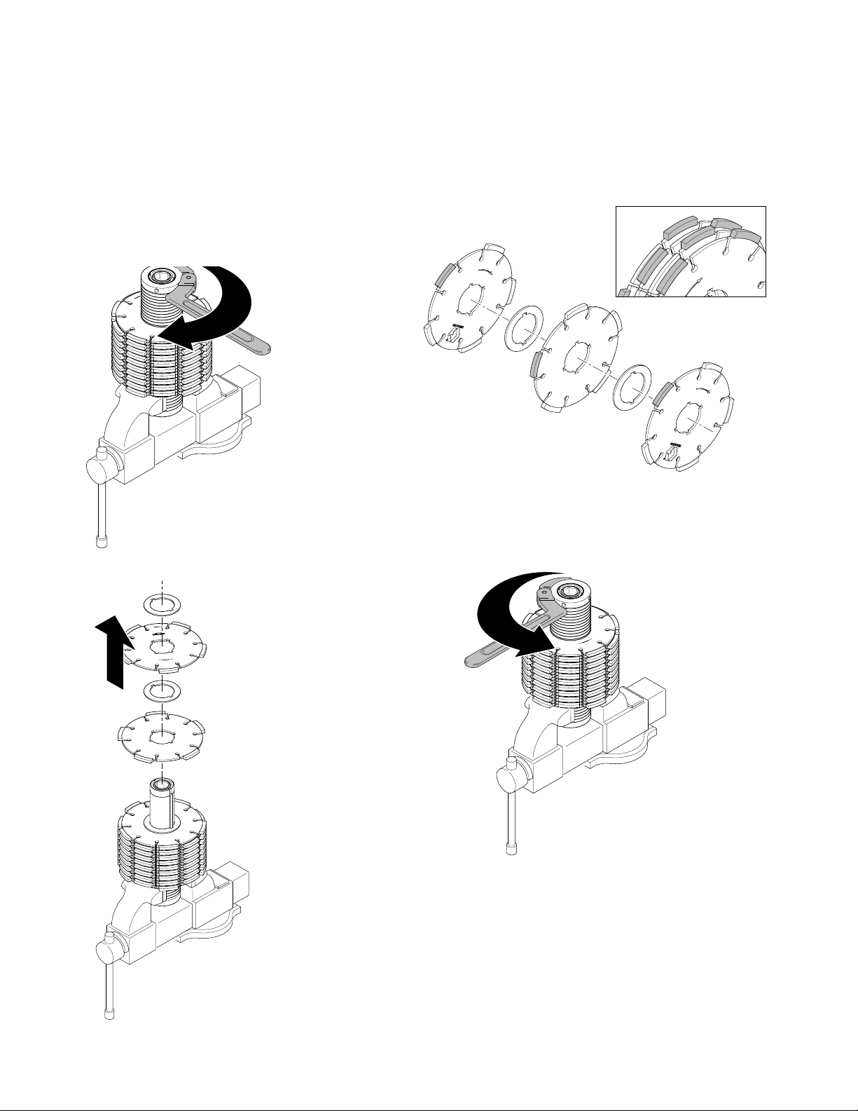
Page 8
Cutter Replacement
Removal (Diamond Blades)
1. Remove drum (see Drum Replacement, page 6).
2. Place drum in vise.
3. Use spanner wrench to loosen spanner nut
(turn clockwise) and remove.
NOTE: This nut has a left-hand thread.
ti15070a
Installation (Diamond Blades)
1. Replace all spacers and diamond blades in the
sequence and orientation shown below (blades
should be rotated in alternating segments when
stacking).
ti15055a
NOTE: Blades must be centered on drum for best
performance.
4. Remove all spacers and diamond blades.
ti15074a
2. Use spanner wrench to tighten spanner nut
(turn counter-clockwise).
ti15084a
3. Remove drum from vise and install drum (see Drum
Replacement, page 6).
8 3A0102C
Page 9
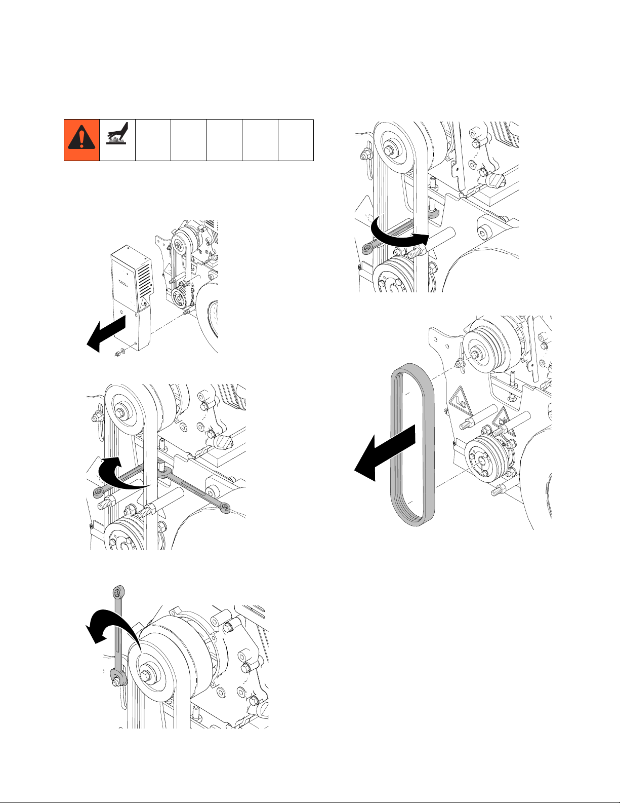
Belt Replacement
Removal
1. Remove three nuts and washers. Remove belt
shroud.
Belt Replacement
4. Tighten bottom bolt to lower pulley plate.
ti15069a
5. Remove used belt.
ti15064a
2. Loosen jam nut through two sides of belt.
ti15085a
3. Use two wrenches to loosen motor mount bolts on
each side of scarifier base.
ti15076a
ti15066a
3A0102C 9
Page 10
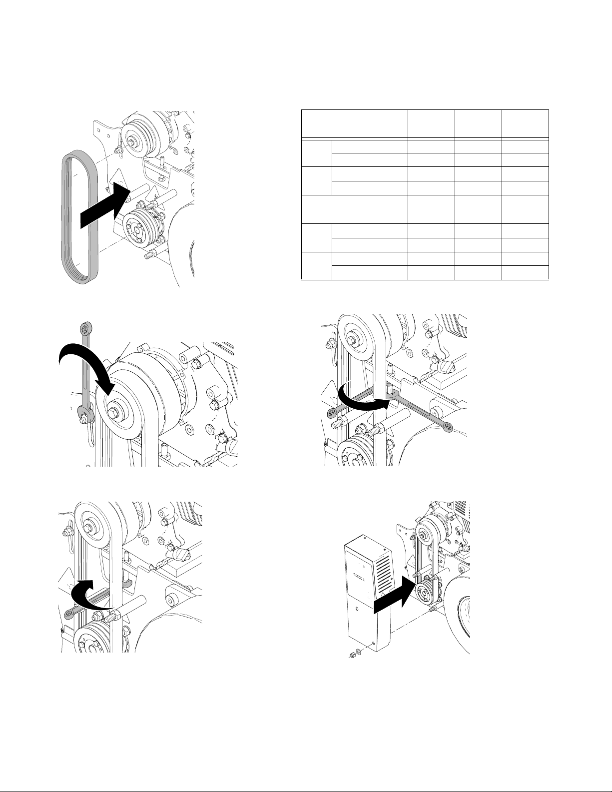
Belt Replacement
Installation
1. Install new belt.
ti15061a
2. Use two wrenches to tighten motor mount adjustment bolts on each side of scarifier base.
Belt Tension Recommendations:
Series A Models
(3VX375 Belt) 270 390 480
New
Belt
Used
Belt
New
Belt
Used
Belt
Tension (Lbf) 130 +/- 5 174 +/- 6 204 +/- 7
Frequency (Hz) 83 +/- 2 96 +/- 2 104 +/- 2
Tension (Lbf) 112 +/- 5 150 +/- 6 176 +/- 7
Frequency (Hz) 77 +/- 2 90 +/- 2 97 +/- 2
Series B Models
(3VX355 Belt) 270 390 480
Tension (Lbf) 145 +/- 5 193 +/- 7 194 +/- 7
Frequency (Hz) 91 +/- 2 105 +/- 2 105 +/- 2
Tension (Lbf) 125 +/- 5 167 +/- 7 167 +/- 7
Frequency (Hz) 85 +/- 2 98 +/- 2 98 +/- 2
4. Tighten jam nut through two sides of belt.
ti15083a
3. Tighten belt adjustment bolt according to recommended tension below.
ti15087a
ti15067a
5. Replace belt shroud and tighten three nuts and four
screws.
ti15058a
10 3A0102C
Page 11

Clutch Replacement
Removal
1. Remove belt guard and belt (see Belt Replacement, page 9).
2. Use impact wrench to remove clutch bolt.
Clutch Replacement
Installation
1. Install clutch.
ti15148a
2. Use impact wrench to tighten clutch bolt.
3. Remove used clutch.
ti15147a
ti15077a
ti15059a
3. Install belt and belt guard (see Belt Replacement,
page 9).
3A0102C 11
Page 12

Pulley Replacement
Pulley Replacement
Removal
1. Remove drum (see Drum Replacement, page 6).
2. Remove belt guard and belt (see Belt Replace-
ment, page 9).
3. Remove three belt pulley screws and washers.
Installation
6. Install pulley onto hex shaft.
ti15131a
7. Insert three pulley screws and washers.
ti15122a
4. Insert three screws into pulley removal holes.
Evenly tighten screws and slowly remove pulley.
ti15121a
5. Remove pulley.
ti15127a
8. Replace belt guard and belt (see Belt Replace-
ment, page 9).
9. Replace drum (see Drum Replacement, page 6).
ti15126a
12 3A0102C
Page 13

Brush Replacement
Removal
1. Remove two mounting bolts.
Brush Replacement
Installation
1. Install new brush.
ti15078b
2. Tighten two mounting bolts.
2. Remove used brush.
ti15072b
ti15068b
ti15078b
3A0102C 13
Page 14

Drive Bearing Assembly Replacement
Drive Bearing Assembly Replacement
2. Install dust cover onto bearing. Hand-tighten nuts
and lock washers to the door. NOTE: Do NOT fully
tighten bolts at this time.
3. Assemble door onto unit and slide door around until
Door Bearing Assembly Removal
1. Remove four nuts holding bearing assembly onto
door and remove door.
the bearing assembly settles into position for proper
alignment.
4. Tighten four nuts on bearing assembly to secure it
into place.
ti17815a
ti14767b
Door Bearing Assembly Installation
1. Insert new door bearing assembly through hole in
door. NOTE: Make sure shaft seal is on the inside of
the cage.
ti15071b
5. Tighten four bolts to hold door in place.
ti17821a
14 3A0102C
Page 15

Drive Bearing Assembly Replacement
Drive Bearing Assembly Removal
1. Remove door from unit and remove any cutting
drum on machine.
ti14767b
ti14765a
2. Remove belt guard and belt (see page 9).
3. Remove sheave.
c. Remove sheave.
ti15126a
d. Remove set screw from bushing.
a. Remove three bolts holding sheave onto
bushing.
ti15122a
b. Insert three bolts into adjacent holes and evenly
tighten to remove sheave from bushing.
ti17819a
e. Remove bushing from drive shaft. If bushing is
very tight, tap a flat-head screwdriver into slot
on bushing to open it up and slide off shaft.
ti17818a
ti15121a
NOTICE
Do NOT over torque an individual bolt or it will break.
3A0102C 15
Page 16

Drive Bearing Assembly Replacement
4. Remove all four nuts holding drive side bearing onto
cage.
ti15123b
5. Slide shaft assembly out of holes.
ti15125b
Drive Bearing Assembly
3. Make sure drive shaft key is assembled as shown
below.
ti17820a
Sheave Installation
1. Insert bushing onto drive shaft. Make sure key is in
place.
ti15146a
2. Apply thread sealant to set screw and install set
screw into bushing.
Installation
1. Insert new drive bearing assembly into cage.
ti15129b
NOTE: Be sure to use the shorter bolts for the drive
side bearing.
2. Tighten nuts and lock washers to hold bearing
assembly in place.
3. Apply thread sealant to bolt and place lock washer
and spacer onto bolt as shown. Thread it into the
end of the shaft and tighten. Make sure lock washer
is fully compressed.
ti17816a
4. Install sheave onto bushing and evenly tighten three
bolts and lock washers to pull the sheave onto the
building.
ti15127a
ti15128b
16 3A0102C
5. Replace belt and belt guard (see page 9).
Page 17

Cutter Stacking Recommendations
Cutter Stacking Recommendations
6 in. (15 cm) Coarse Cut Flail Cutters (Double Space) 276 Spacers / 60 Cutters
INSTRUCTIONS: Rotate sequence 180° and repeat for
remaining shafts.
15 (S)
1 (C)
2 (S)
1 (C)
2 (S)
1 (C)
2 (S)
1 (C)
1 (S)
1 (C)
1 (S)
1 (C)
1 (S)
3 (S)
1 (C)
2 (S)
1 (C)
2 (S)
1 (C)
2 (S)
1 (C)
13 (S)
1 (C)
2 (S)
1 (C)
2 (S)
1 (C)
2 (S)
1 (C)
3 (S)
1 (C)
1 (S)
1 (C)
2 (S)
1 (C)
1 (S)
1 (C)
2 (S)
1 (C)
1 (S)
13 (S)
ti15045a
(S) Spacer
(C) Carbide Cutter
15 (S)
ti15053a
3A0102C 17
Page 18

Cutter Stacking Recommendations
8 in. (20 cm) Coarse Cut Flail Cutters (Double Space) 234 Spacers / 84 Cutters
INSTRUCTIONS: Rotate sequence 180° and repeat for
remaining shafts.
8 (S)
1 (C)
2 (S)
1 (C)
2 (S)
1 (C)
2 (S)
1 (C)
2 (S)
1 (C)
2 (S)
1 (C)
1 (S)
1 (C)
1 (S)
1 (C)
1 (S)
3 (S)
1 (C)
2 (S)
1 (C)
2 (S)
1 (C)
2 (S)
1 (C)
2 (S)
1 (C)
2 (S)
1 (C)
5 (S)
5 (S)
1 (C)
2 (S)
1 (C)
2 (S)
1 (C)
2 (S)
1 (C)
2 (S)
1 (C)
2 (S)
1 (C)
3 (S)
1 (S)
1 (C)
1 (S)
1 (C)
1 (S)
1 (C)
2 (S)
1 (C)
2 (S)
1 (C)
2 (S)
1 (C)
2 (S)
1 (C)
2 (S)
14 (S)
ti15046a
ti15053a
(S) Spacer
(C) Carbide Cutter
18 3A0102C
Page 19

Cutter Stacking Recommendations
10 in. (25 cm) Coarse Cut Flail Cutters (Double Space) 210 Spacers / 102 Cutters
INSTRUCTIONS: Rotate sequence 180° and repeat for
remaining shafts.
1 (S)
1 (C)
2 (S)
1 (C)
2 (S)
1 (C)
2 (S)
1 (C)
2 (S)
1 (C)
2 (S)
1 (C)
2 (S)
1 (C)
2 (S)
1 (C)
1 (S)
1 (C)
1 (S)
1 (C)
1 (S)
2 (S)
1 (C)
2 (S)
1 (C)
2 (S)
1 (C)
2 (S)
1 (C)
2 (S)
1 (C)
2 (S)
1 (C)
2 (S)
1 (C)
3 (S)
3 (S)
1 (C)
2 (S)
1 (C)
2 (S)
1 (C)
2 (S)
1 (C)
2 (S)
1 (C)
2 (S)
1 (C)
2 (S)
1 (C)
2 (S)
1 (S)
1 (C)
1 (S)
1 (C)
1 (S)
1 (C)
2 (S)
1 (C)
2 (S)
1 (C)
2 (S)
1 (C)
2 (S)
1 (C)
2 (S)
1 (C)
2 (S)
1 (C)
2 (S)
1 (C)
2 (S)
ti15047a
ti15053a
(S) Spacer
(C) Carbide Cutter
3A0102C 19
Page 20

Cutter Stacking Recommendations
6 in. (15 cm) General Cut Flail Cutters (Single Space) 234 Spacers / 84 Cutters
INSTRUCTIONS: Rotate drum 180° and repeat for
remaining shafts.
14 (S)
1 (C)
1 (S)
1 (C)
1 (S)
1 (C)
1 (S)
1 (C)
1 (S)
1 (C)
1 (S)
1 (S)
3 (C)
1 (S)
1 (C)
1 (S)
1 (C)
1 (S)
1 (C)
1 (S)
1 (C)
1 (S)
1 (C)
1 (S)
1 (C)
12 (S)
1 (C)
1 (S)
1 (C)
1 (S)
1 (C)
1 (S)
1 (C)
1 (S)
1 (C)
1 (S)
1 (C)
1 (S)
3 (C)
1 (S)
2 (S)
1 (C)
1 (S)
1 (C)
1 (S)
1 (C)
1 (S)
1 (C)
1 (S)
1 (C)
12 (S)
ti15042a
(S) Spacer
(C) Carbide Cutter
14 (S)
ti15053a
20 3A0102C
Page 21

Cutter Stacking Recommendations
8 in. (20 cm) General Cut Flail Cutters (Single Space) 186 Spacers / 114 Cutters
INSTRUCTIONS: Rotate drum 180° and repeat for
remaining shafts.
7 (S)
1 (C)
1 (S)
1 (C)
1 (S)
1 (C)
1 (S)
1 (C)
1 (S)
1 (C)
1 (S)
1 (C)
1 (S)
1 (C)
1 (S)
1 (C)
1 (S)
3 (C)
1 (S)
2 (S)
1 (C)
1 (S)
1 (C)
1 (S)
1 (C)
1 (S)
1 (C)
1 (S)
1 (C)
1 (S)
1 (C)
1 (S)
1 (C)
1 (S)
1 (C)
6 (S)
1 (C)
1 (S)
1 (C)
1 (S)
1 (C)
1 (S)
1 (C)
1 (S)
1 (C)
1 (S)
1 (C)
1 (S)
1 (S)
1 (C)
2 (S)
3 (C)
1 (S)
1 (C)
1 (S)
1 (C)
1 (S)
1 (C)
1 (S)
1 (C)
1 (S)
1 (C)
1 (S)
1 (C)
1 (S)
1 (C)
1 (S)
1 (C)
6 (S)
ti15043a
(S) Spacer
(C) Carbide Cutter
7 (S)
ti15053a
3A0102C 21
Page 22

Cutter Stacking Recommendations
10 in. (25 cm) General Cut Flail Cutters (Single Space) 150 Spacers / 138 Cutters
INSTRUCTIONS: Rotate drum 180° and repeat for
remaining shafts.
1 (S)
1 (C)
1 (S)
1 (C)
1 (S)
1 (C)
1 (S)
1 (C)
1 (S)
1 (C)
1 (S)
1 (C)
1 (S)
1 (C)
1 (S)
1 (C)
1 (S)
1 (C)
1 (S)
1 (C)
2 (S)
ti15044a
1 (S)
3 (C)
1 (S)
1 (C)
1 (S)
1 (C)
1 (S)
1 (C)
1 (S)
1 (C)
1 (S)
1 (C)
1 (S)
1 (C)
1 (S)
1 (C)
1 (S)
1 (C)
1 (S)
1 (C)
1 (S)
1 (C)
2 (S)
ti15053a
(S) Spacer
(C) Carbide Cutter
22 3A0102C
Page 23

6 in. (15 cm) Fine Cut Flail Cutters 198 Spacers / 108 Cutters
INSTRUCTIONS: Rotate sequence 180° and repeat for
remaining shafts.
12 (S)
13 (C)
1 (C)
Cutter Stacking Recommendations
14 (S)
1 (C)
1 (S)
1 (C)
1 (S)
1 (C)
1 (S)
1 (C)
1 (S)
1 (C)
2 (S)
1 (S)
9 (C)
13 (S)
ti15048a
1 (S)
3 (C)
1 (S)
1 (C)
1 (S)
1 (C)
1 (S)
1 (C)
1 (S)
1 (C)
1 (S)
1 (C)
1 (S)
1 (C)
12 (S)
ti15053a
(S) Spacer
(C) Carbide Cutter
3A0102C 23
Page 24

Cutter Stacking Recommendations
8 in. (20 cm) Fine Cut Flail Cutters 138 Spacers / 144 Cutters
INSTRUCTIONS: Rotate sequence 180° and repeat for
remaining shafts.
7 (S)
16 (C)
1 (S)
6 (S)
1 (C)
1 (S)
1 (C)
1 (S)
1 (C)
1 (S)
1 (C)
1 (S)
1 (C)
1 (S)
1 (C)
1 (S)
1 (C)
1 (S)
1 (C)
2 (S)
1 (S)
13 (C)
6 (S)
ti15049a
1 (S)
3 (C)
1 (S)
1 (C)
1 (S)
1 (C)
1 (S)
1 (C)
1 (S)
1 (C)
1 (S)
1 (C)
1 (S)
1 (C)
1 (S)
1 (C)
1 (S)
1 (C)
7 (S)
ti15053a
(S) Spacer
(C) Carbide Cutter
24 3A0102C
Page 25

10 in. (25 cm) Fine Cut Flail Cutters 90 Spacers / 174 Cutters
INSTRUCTIONS: Rotate sequence 180° and repeat for
remaining shafts.
Cutter Stacking Recommendations
1 (S)
16 (C)
1 (S)
1 (S)
19 (C)
2 (S)
1 (S)
1 (C)
1 (S)
1 (C)
1 (S)
1 (C)
1 (S)
1 (C)
1 (S)
1 (C)
1 (S)
1 (C)
1 (S)
1 (C)
1 (S)
1 (C)
1 (S)
1 (C)
1 (S)
1 (C)
2 (S)
1 (S)
3 (C)
1 (S)
1 (C)
1 (S)
1 (C)
1 (S)
1 (C)
1 (S)
1 (C)
1 (S)
1 (C)
1 (S)
1 (C)
1 (S)
1 (C)
1 (S)
1 (C)
1 (S)
1 (C)
1 (S)
1 (C)
2 (S)
ti15050a
ti15053a
(S) Spacer
(C) Carbide Cutter
3A0102C 25
Page 26

Cutter Stacking Recommendations
6 in. (15 cm) Cut Carbide Millers 204 Spacers / 30 Cutters
INSTRUCTIONS: Rotate sequence 180° and repeat for
remaining shafts.
14 (S)
1 (M)
1 (S)
1 (M)
1 (S)
1 (M)
1 (S)
1 (S)
1 (M)
1 (S)
1 (M)
15 (S)
1 (M)
3 (S)
1 (M)
1 (S)
1 (M)
1 (S)
1 (M)
4 (S)
1 (M)
15 (S)
ti15096a
ti15056a
(S) Spacer
14 (S)
(M) Miller
26 3A0102C
Page 27

8 in. (20 cm) Cut Carbide Millers 132 Spacers / 42 Cutters
INSTRUCTIONS: Rotate sequence 180° and repeat for
remaining shafts.
Cutter Stacking Recommendations
7 (S)
1 (M)
1 (S)
1 (M)
1 (S)
1 (M)
1 (S)
1 (M)
1 (S)
1 (S)
1 (M)
1 (S)
1 (M)
1 (S)
1 (M)
8 (S)
1 (M)
1 (S)
1 (M)
1 (S)
1 (M)
1 (S)
1 (S)
1 (M)
1 (S)
1 (M)
1 (S)
1 (M)
1 (S)
1 (M)
8 (S)
ti15051a
ti15056a
(S) Spacer
7 (S)
(M) Miller
3A0102C 27
Page 28

Cutter Stacking Recommendations
10 in. (25 cm) Cut Carbide Millers 66 Spacers / 54 Cutters
INSTRUCTIONS: Rotate sequence 180° and repeat for
remaining shafts.
1 (S)
1 (M)
1 (S)
1 (M)
1 (S)
1 (M)
1 (S)
1 (M)
1 (S)
1 (M)
1 (S)
1 (S)
1 (M)
1 (S)
1 (M)
1 (S)
1 (M)
1 (S)
1 (M)
1 (S)
1 (S)
1 (M)
1 (S)
1 (M)
1 (S)
1 (M)
1 (S)
1 (M)
1 (S)
1 (S)
1 (M)
1 (S)
1 (M)
1 (S)
1 (M)
1 (S)
1 (M)
1 (S)
1 (M)
1 (S)
ti15052a
ti15056a
(S) Spacer
(M) Miller
28 3A0102C
Page 29

Diamond Blades
Cutter Stacking Recommendations
Groove
Width
Number
of Blades
Number of
Steel 1/8 in.
Spacers
Number of
Aluminum 1/4
in. Spacers
1 in. (2.5 cm) 4 5 36
2 in. (5 cm) 8 9 32
3 in. (7.5 cm) 12 13 28
4 in. (10 cm) 16 17 23
5 in. (12.5 cm) 19 21 21
6 in. (15 cm) 23 24 15
7 in. (17.5 cm) 27 28 11
8 in. (20 cm) 31 32 7
9 in. (23 cm) 35 36 3
10 in. (25 cm) 38 39 2
For best performance, use 1/4 in. spacers on each end of
shaft to center diamond blades on drum.
1/4 in. Spacers
1/4 in. Spacers
ti15135a
1/8 in. Spacers
1 (D)
NOTE: Be sure to rotate the blade 180 degrees
every time an additional blade is added to a stack.
1 (SE)
1 (D)
(SQ) Spacer-1/4 in.
1 (SE)
1 (D)
(SE) Spacer-1/8 in.
ti15055a
ti15054a
(D) Diamond Blade
3A0102C 29
Page 30

Troubleshooting
Troubleshooting
Problem Cause Solution
Engine will not start Engine switch is OFF. Turn engine switch ON.
Engine is out of gas. Refill gas tank (see engine manual.
Engine oil level is low. Try to start engine. Fill oil is necessary (see
engine manual).
Spark plug cable is disconnected or damaged.
Engine is cold. Use engine choke.
Fuel shutoff lever is in OFF position. Move shutoff lever to ON position.
Oil is seeping into combustion chamber. Remove spark plug. Pull starter 3 or 4 times.
480 Models Only: Emergency shut-off
switch is OFF.
480 Models: Not attached to LineDriver. Attach LineDriver to unit.
Engine operates, LineDriver will not
move forward or reverse
Engine operates, LineDriver moves
slowly in forward or reverse
Engine shuts off when operator exits
LineDriver
Engine continues to run when operator exits LineDriver and parking
brake is not set
Engine misses during turns and forward and reverse changes
Uneven cut Unbalanced tire pressure Check tire pressure to make sure both tires
Not cutting Cutters are worn or damaged Replace cutters.
Engine runs for short time and stops Fuel flow restriction See engine manual
Unit vibrates excessively Cutters not centered on drum. Reassemble drum with cutters centered on
Groove is not even when using diamond blades
Engine bogs down while
grinding
Not removing material while cutting Cutters are worn. Replace cutters.
Low hydraulic oil Fill with Mobil 1 (15W-50) synthetic oil
Wheel release is open Close; hand tighten.
Low hydraulic oil. Parking brake is set. Fill with Mobil (15W-050) synthetic oil.
Wheel release is open Close; hand tighten.
Safety switch Set parking brake
Safety switch Adjust and set parking brake. Replace safety
Engine oil low 1. Consult engine manual for proper oil.
Bearings are starting to wear out. Replace bearings.
Cutters are worn or damaged. Replace cutters.
Drum rod is not level with drum adjustment
wheels.
Depth of cut is too deep. Raise drum.
Unit is moving too fast. Slow down.
Connect spark plug cable or replace spark
plug.
Clean or replace spark plug. Start engine.
Keep sprayer upright to avoid oil seepage.
Turn emergency shut-off switch ON.
Release parking brake.
switch and/or any connecting wires.
2. Keep engine oil full to avoid nuisance
stalls caused by Oil Alert sensing low oil
levels.
are at 60 ft-lb.
drum.
Adjust drum adjustment wheels so wheels
and hex rod are level.
30 3A0102C
Page 31

Technical Data
GrindLazer 270
(Model 571002)
Dimensions
Unpackaged Packaged
Height in./cm: 46 (116.8) 50.5 (128.3)
Width in./cm: 28 (71.1) 37 (94.0)
Length in.cm: 62 (157.5) 73 (185.4)
Weight lb/kg: 300 (136) 400 (181)
Noise (dBa)
Sound Power per ISO 3744: 107.3
Sound Pressure measured at 3.1 feet (1m): 91.6
Vibration (m/sec
Without LineDriver: 7.9
With LineDriver: 8.3
Power Rating (HorsePower) per SAE J1349
8.0 @ 3600 rpm
GrindLazer 390
(Model 571003)
Height in./cm: 46 (116.8) 50.5 (128.3)
Width in./cm: 28 (71.1) 37 (94.0)
Length in.cm: 62 (157.5) 73 (185.4)
Weight lb/kg: 310 (141) 410 (186)
Sound Power per ISO 3744: 109.3
Sound Pressure measured at 3.1 feet (1m): 93.6
Vibration (m/sec
Without LineDriver: 7.5
With LineDriver: 5.9
Power Rating (HorsePower) per SAE J1349
11.0 @ 3600 rpm
GrindLazer 480
(Model 571004)
Height in./cm: 46 (116.8) 50.5 (128.3)
Width in./cm: 28 (71.1) 37 (94.0)
Length in.cm: 62 (157.5) 73 (185.4)
Weight lb/kg: 330 (150) 430 (195)
Sound Power per ISO 3744: 108.6
Sound Pressure measured at 3.1 feet (1m): 92.1
Vibration (m/sec
With LineDriver: 4.9
Power Rating (HorsePower) per SAE J1349
16.0 @ 3600 rpm
2
) per ISO 3744
Dimensions
Noise (dBa)
2
) per ISO 3744
Dimensions
Noise (dBa)
2
) per ISO 3744
Unpackaged Packaged
Unpackaged Packaged
Technical Data
3A0102C 31
Page 32

Graco Standard Warranty
Graco warrants all equipment referenced in this document which is manufactured by Graco and bearing its name to be free from defects in
material and workmanship on the date of sale to the original purchaser for use. With the exception of any special, extended, or limited warranty
published by Graco, Graco will, for a period of twelve months from the date of sale, repair or replace any part of the equipment determined by
Graco to be defective. This warranty applies only when the equipment is installed, operated and maintained in accordance with Graco’s written
recommendations.
This warranty does not cover, and Graco shall not be liable for general wear and tear, or any malfunction, damage or wear caused by faulty
installation, misapplication, abrasion, corrosion, inadequate or improper maintenance, negligence, accident, tampering, or substitution of
non-Graco component parts. Nor shall Graco be liable for malfunction, damage or wear caused by the incompatibility of Graco equipment with
structures, accessories, equipment or materials not supplied by Graco, or the improper design, manufacture, installation, operation or
maintenance of structures, accessories, equipment or materials not supplied by Graco.
This warranty is conditioned upon the prepaid return of the equipment claimed to be defective to an authorized Graco distributor for verification of
the claimed defect. If the claimed defect is verified, Graco will repair or replace free of charge any defective parts. The equipment will be returned
to the original purchaser transportation prepaid. If inspection of the equipment does not disclose any defect in material or workmanship, repairs will
be made at a reasonable charge, which charges may include the costs of parts, labor, and transportation.
THIS WARRANTY IS EXCLUSIVE, AND IS IN LIEU OF ANY OTHER WARRANTIES, EXPRESS OR IMPLIED, INCLUDING BUT NOT LIMITED
TO WARRANTY OF MERCHANTABILITY OR WARRANTY OF FITNESS FOR A PARTICULAR PURPOSE.
Graco’s sole obligation and buyer’s sole remedy for any breach of warranty shall be as set forth above. The buyer agrees that no other remedy
(including, but not limited to, incidental or consequential damages for lost profits, lost sales, injury to person or property, or any other incidental or
consequential loss) shall be available. Any action for breach of warranty must be brought within two (2) years of the date of sale.
GRACO MAKES NO WARRANTY, AND DISCLAIMS ALL IMPLIED WARRANTIES OF MERCHANTABILITY AND FITNESS FOR A
PARTICULAR PURPOSE, IN CONNECTION WITH ACCESSORIES, EQUIPMENT, MATERIALS OR COMPONENTS SOLD BUT NOT
MANUFACTURED BY GRACO. These items sold, but not manufactured by Graco (such as electric motors, switches, hose, etc.), are subject to
the warranty, if any, of their manufacturer. Graco will provide purchaser with reasonable assistance in making any claim for breach of these
warranties.
In no event will Graco be liable for indirect, incidental, special or consequential damages resulting from Graco supplying equipment hereunder, or
the furnishing, performance, or use of any products or other goods sold hereto, whether due to a breach of contract, breach of warranty, the
negligence of Graco, or otherwise.
FOR GRACO CANADA CUSTOMERS
The Parties acknowledge that they have required that the present document, as well as all documents, notices and legal proceedings entered into,
given or instituted pursuant hereto or relating directly or indirectly hereto, be drawn up in English. Les parties reconnaissent avoir convenu que la
rédaction du présente document sera en Anglais, ainsi que tous documents, avis et procédures judiciaires exécutés, donnés ou intentés, à la suite
de ou en rapport, directement ou indirectement, avec les procédures concernées.
All written and visual data contained in this document reflects the latest product information available at the time of publication.
Graco reserves the right to make changes at any time without notice.
Original instructions. This manual contains English. MM 3A0102
Graco Headquarters: Minneapolis
International Offices: Belgium, China, Japan, Korea
GRACO INC. AND SUBSIDIARIES • P.O. BOX 1441 • MINNEAPOLIS MN 55440-1441 • USA
Copyright 2011, Graco Inc. All Graco manufacturing locations are registered to ISO 9001.
www.graco.com
Revised 09/2011
 Loading...