

Page 1
Operation
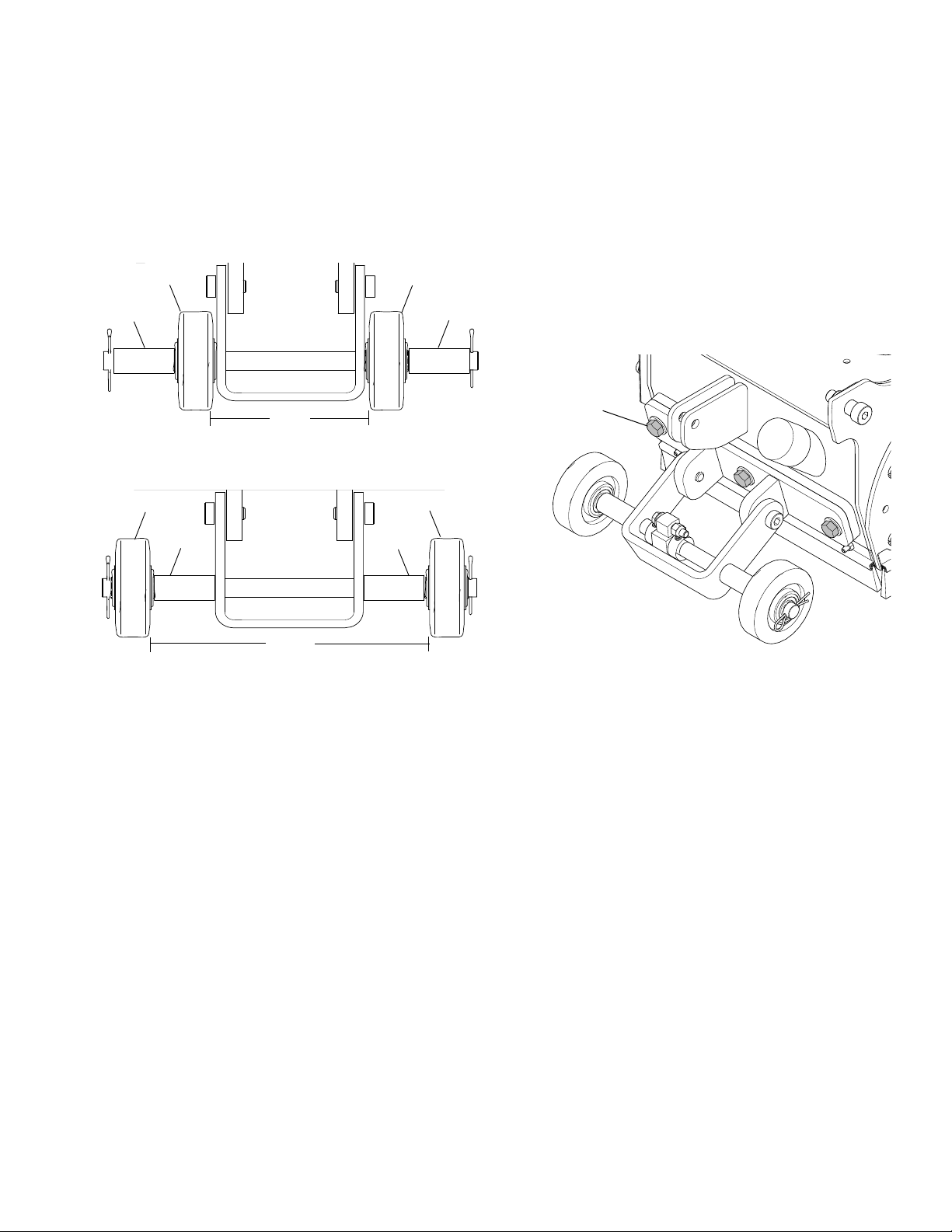
ti14752a
ti14763a
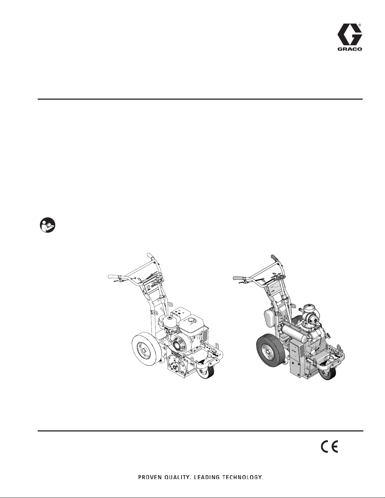
GrindLazer 270 and 390
GrindLazer 630
(Drums, cutters, and LineDriver
™
sold separately)
Related Manuals:
Repair - 3A0102
Parts - 3A0103
ti25371a
™
GrindLazer
Designed to grind flat, horizontal concrete or asphalt surfaces. For removal of materials
from concrete and asphalt surfaces. For professional outdoor use only
Model 571002 - Forward cut
GrindLazer 270 (270 cc / 9 hp)
Model 571003 - Forward cut
GrindLazer 390 (390 cc / 13 hp)
Model 571004 - Reverse up-cut (Must be used with LineDriver
GrindLazer 480 (480cc / 16 hp)
™
)
3A0101C
EN
Model 571260 - Reverse up-cut (Must be used with LineDriver
GrindLazer 630 (627 cc / 21 hp)
IMPORTANT SAFETY INSTRUCTIONS
Read all warnings and instructions in this
manual. Save these instructions.
™
)
Page 2

Warnings
Warnings
The following warnings are for the setup, use, grounding, maintenance, and repair of this equipment. The
exclamation point symbol alerts you to a general warning and the hazard symbol refers to procedure-specific risk.
Refer back to these warnings. Additional, product-specific warnings may be found throughout the body of this manual
where applicable.
WARNING
DUST AND DEBRIS HAZARD
Use of this equipment to grind concrete and other paving materials can result in the release of potentially
harmful dust or chemicals from the materials.
• For use only by sophisticated users familiar with applicable governmental safety and industrial
hygiene regulations.
• Use equipment only in a well-ventilated area.
• Wear a properly fit-tested and government approved respirator suitable for the dust conditions.
EQUIPMENT MISUSE HAZARD
Misuse can cause death or serious injury.
• Do not operate the unit when fatigued or under the influence of drugs or alcohol.
• Do not leave the work area while equipment is energized. Turn off all equipment when equipment is
not in use.
• Check equipment daily. Repair or replace worn or damaged parts immediately with genuine manufacturer’s replacement parts only.
• Do not alter or modify equipment.
• Use equipment only for its intended purpose. Call your distributor for information.
• Keep children and animals away from work area.
• Comply with all applicable safety regulations.
• Maintain a safe operating distance from other people in the work area.
• Avoid any pipes, columns, openings, or any other objects protruding from work surface.
MOVING VEHICLE HAZARD
Careless and reckless behavior causes accidents. Falling from vehicle, running into people or object, or
being struck by other vehicles may result in serious injury or death.
• Do not step on forward/reverse pedals.
• Make turns slowly. Do not make turns greater than 45°.
• Loss of traction may occur going downhill. Do not operate on slopes greater than 15°.
• Do not carry passengers.
• Do not tow.
• Use with line striping equipment only.
• Use appropriate traffic control in all traffic areas. Refer to Manual on Uniform Traffic Control Devices
(MUTCD), U.S. Department of Transportation, Federal Highway Administration or local highway and
transportation regulations.
MOVING PARTS HAZARD
Moving parts can pinch or amputate fingers and other body parts.
• Keep clear of moving parts.
• Do not operate equipment with protective guards or covers removed.
• Before checking, moving, or servicing equipment, disable power supply.
BURN HAZARD
Equipment surfaces that are heated can become very hot during operation. To avoid severe burns, do
not touch hot equipment. Wait until equipment has cooled completely.
2 3A0101C
Page 3
Warnings
WARNING
FIRE AND EXPLOSION HAZARD
Flammable fumes, such as solvent and paint fumes, in work area can ignite or explode. To help prevent
fire and explosion:
• Use equipment only in well ventilated area.
• Do not fill fuel tank while engine is running or hot; shut off engine and let it cool. Fuel is flammable
and can ignite or explode if spilled on hot surface.
• Keep work area free of debris, including solvent, rags and gasoline.
• Keep a fire extinguisher in work area.
CARBON MONOXIDE HAZARD
Exhaust contains poisonous carbon monoxide, which is colorless and odorless. Breathing carbon
monoxide can cause death. Do not operate in an enclosed area.
PERSONAL PROTECTIVE EQUIPMENT
You must wear appropriate protective equipment when operating, servicing, or when in the operating
area of the equipment to help protect you from serious injury, including eye injury, inhalation of dust or
chemicals, burns, and hearing loss. This equipment includes but is not limited to:
• Protective eye wear
• Protective shoes
• Gloves
• Hearing protection
• Properly fit-tested and government approved respirator suitable for the dust conditions
CALIFORNIA PROPOSITION 65
The engine exhaust from this product contains a chemical known to the State of California to cause
cancer, birth defects or other reproductive harm.
This product contains a chemical known to the State of California to cause cancer, birth defects or other
reproductive harm. Wash hands after handling.
3A0101C 3
Page 4
Component Identification
ti14753a
G
E
C
B
A
F
D
H
K
C
B
A
270 and 390 Models
480/630 Models
M
N
D
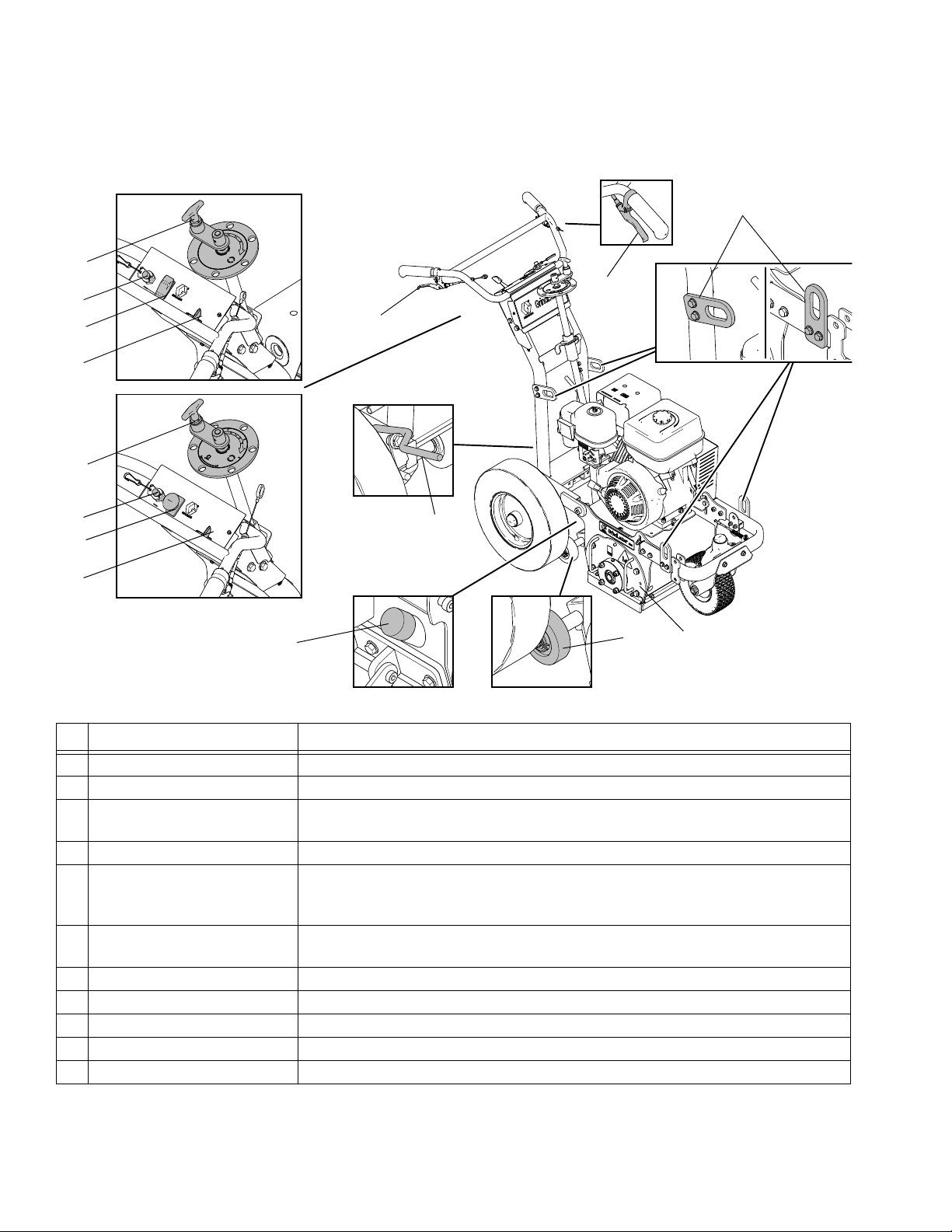
Component Identification
Component Description
A Engine Throttle Lever Adjusts engine speed.
B Engine Stop Switch Supplies power to Engine
C Emergency Shut-Off Clamps onto the operator and shuts engine off if cord is disconnected during
operation.
D Drum Adjustment Dial Sets depth of drum cut.
E Drum Engage Lever When lever is engaged, handle bars can be pushed down to raise the cutting
F Front Wheel Lock Lever Front wheel is usually locked to guide GrindLazer in a straight line. When lever
G Rear Wheel Parking Brake Prevents rear wheel from moving.
H Drum Access Panel Removable plate that allows access to replace cutting drum.
K Depth Control Wheels Levels cutting drum.
M Vacuum Port Port to attach vacuum to reduce dust and debris during operation.
N Lift Points Reinforced points used for lifting GrindLazer during transportaton or repair.
drum off of surface and locked into UP position. Once drum is locked in UP
position, GrindLazer can be moved around without drum touching surface.
is engaged, front wheel becomes unlocked and is allowed to turn freely.
4 3A0101C
Page 5

Operation
Operation
The GrindLazer is designed to plane flat, horizontal concrete or asphalt slabs.
GrindLazer 270 (270 cc) and GrindLazer 390 (390 cc)
models are designed to be operated by a single
operator positioned at the back of the unit, or in
conjunction with LineDriver. GrindLazer 480 (480 cc)
and GrindLazer 630 (627 cc) can ONLY be operated
with LineDriver.
Maintain a safe operating distance from other people in
the work area. Avoid any pipes, columns, openings, or
any other objects protruding from work surface.
Start-Up
Before starting engine, perform the following:
• Read and understand engine manual
• Make sure all guards are in place and secure
• Make sure all mechanical fasteners are secure
• Inspect for damage to engine and other exterior
surfaces
• Use correct cutters for each job. Make sure drum is
balanced and the correct number, size and type of
cutter wheels are being used. Make sure drum shaft
is locked and secured.
• Inspect work area to locate any pipes, columns,
deck inserts, or other objects protruding from work
surface. Avoid these objects during operation.
3A0101C 5
Page 6
Operation
Carbide Miller
Diamond Blade
ti15142a
ti15141a
Forward Cut (270/390 Models)
Reverse (up cut) 480/630
ti15138a
ti15137a
ti14766a
ti14764a
ti14756a
ti14755a
ti15256a
ti15257a
ti14767a
ti14765a
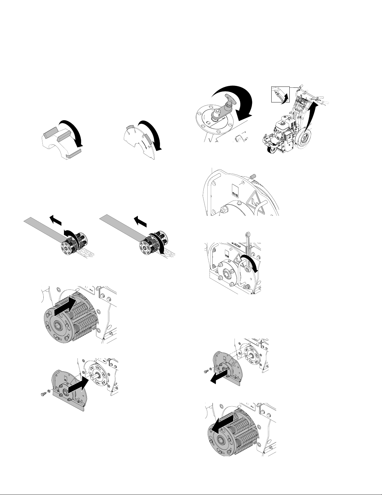
Drum Installation/Replacement
Installation
NOTE: Carbide Flail Cutter drums do not require
specific orientation or direction. Carbide Millers and
Diamond Blades are directional. They should be
stacked so that the arrows on the Millers and Blades
face the same direction as the rotation of the drum.
270 and 390 models are designed for “forward cut”
grinding (the drum rotates in the same direction that it
travels). 480 and 630 models are design for “reverse (up
cut)” grinding (the drum rotates in the opposite direction
that it travels).
3. Lower Drum Adjustment Dial (D) and pull Drum
Engage Lever (E) so drum rests on ground.
Door pin and hole should line up.
4. Tighten four bolts on Drum Access Panel (H).
1. Slide replacement Drum onto hex shaft.
2. Replace Drum Access Panel (H).
5. Turn Drum Adjustment Dial (D) to maximum height.
Removal
1. Remove four bolts and Drum Access Panel (H).
2. Slide drum off of hex shaft.
6 3A0101C
Page 7

Starting the Engine
ti14754a
ti15089a
ti14758a
ti15088a
ti5248a
480 Models270/390 Models
ti15091a
ti5249a
480 Models
270/390 Models
630 Models
ti3315a
ti14872a
270 & 390 Models
480/630 Models
ti5263a
TIA
480 Models270/390 Models
630 Models
ti6483a
3. Engage Rear Wheel Brake (G) to prevent GrindLazer from moving.
4. 480/630 Models Only: Attach LineDriver to
GrindLazer.
Operation
7. Start Engine:
a. Move fuel valve to open.
b. Move choke to closed.
c. Set Engine Power Switch (B) to ON.
5. Push down on handle bars until drum is locked into
UP position.
6. 480/630 Models Only: Make sure Engine Stop
Switch (C) is in UP position.
d. Pull starter cord.
e. After engine starts, move choke to open.
f. Set throttle to desired setting.
3A0101C 7
Page 8

Operation
ti14762a
ti14757a
ti6483a
ti14755a
ti14756a
Cutting Material
1. Start Engine, see page 7.
2. Connect Emergency Shut-Off Cord (C) to operator.
3. Disengage Rear Wheel Brake (G).
5. Push down on handle bars, pull engagement lever,
and lower drum into DOWN position.
6. Rotate Drum Adjustment Dial (D) until drum comes
into contact with surface and desired depth is
reached.
4. Slide Engine Throttle Lever (A) to desired setting.
NOTE: Drum clutch will not engage when engine is
running at idle. 480/630 Models: LineDriver must
be attached to GrindLazer.
NOTE: Several test cuts may be needed to dial-in
desired cutting depth.
NOTE: On harder surfaces, it may be best to make
several passes in increments of 1/32 in. to 1/8 in.
8 3A0101C
Page 9
Operation
S
S
K
K
ti15095a
5 in.
S
S
K
K
ti15094a
10 in.
T
ti15229a
Depth Control Wheels
Using Depth Control Wheels as a 5 in. or
10 in. Wide Cutting Guide
To make a 5 in. cut, install two spacers (S) on outside
of Depth Control Wheels (K).
To make a 10 in. cut, install two spacers (S) on inside
of Depth Control Wheels (K).
How to Level the Drum
To properly level the drum, GrindLazer must be resting
on a flat level surface.
1. Make sure drum is properly installed (see Drum
Replacement, page 6).
2. Push down on handle bars, pull engagement lever,
and lower drum into DOWN position.
3. Loosen (but do not remove) three bolts (T) on Depth
Control Wheel plate.
4. Adjust plate until guide wheels lay flat on surface.
5. Tighten three bolts (T) on plate.
3A0101C 9
Page 10

Operation
ti14758a
ti6482a
ti15176a
270 & 390 Models
480/630 Models
ti15177a
Stop Cutting Material
1. Push down on handle bars until drum is locked into
UP position.
3. Turn Engine Power Switch (B) OFF.
Clean Up
Clean the entire exterior of the machine after it has
cooled at the end of each work day. Check for worn or
damaged parts and perform any required Maintenance,
page 12.
2. Slide Engine Throttle Lever (A) to low setting.
10 3A0101C
Page 11

Cutting Drum Assemblies
S
S
Avoid touching or handling drum after use until it has
completely cooled.
Different drum configurations can be used for different
applications. There are three different types of drum
assemblies compatible with the GrindLazer: carbide
flails, carbide millers, and diamond blades.
Carbide Flail Cutter/Assembly
Gradually adjust depth down to remove marking line
(minimal amount of paved surface should be removed).
Carbide Miller Cutter/Assembly
Best results for deep cuts are achieved by making several thin passes. A single pass should be no deeper
than 1/32 in. or damage to rods and cutters could occur.
Cutting Drum Assemblies
NOTE: Each increment on Drum Adjustment Dial (D) is
0.010 in. (0.25 mm) depth change of cutting drum.
Diamond Blade Assembly
(480/630 Models Only)
Watch Depth Control Wheels (K) during operation; if
wheels are spinning, proper depth is being achieved.
NOTICE
Diamond Blades are designed to be cooled by airflow around the blades. Lift blade out of cut every
10 to 15 seconds, then run at full speed for several
seconds to prevent excessive heat build-up which
could damage the blades.
Cutter and Drum Assemblies
• The engine should not labor. Run engine at full
speed and adjust forward speed to fit the work being
performed. Harder concrete surfaces will have to be
cut at a slower pace than asphalt or other softer surfaces.
Handle Bar Adjustment
To adjust handle bar: remove four screws (S), slide
handle bar to desired height, and replace screws and
tighten.
3A0101C 11
Page 12

Maintenance
ti14760a
Maintenance
Avoid touching engine and drum after use until they
have completely cooled.
The following steps should be performed to maintain
proper operation and sustain the life of the GrindLazer.
BEFORE OPERATION:
• Visually inspect the entire unit for damage or loose
connections
• Insert grease into the grease fittings on the drum
mount and center hinge
• Check engine oil (see engine manual)
• Check drum bushings and cutters
• Check drum for uneven wear
• Check for proper tire pressure
DAILY:
• Insert and clean air filter element
• Clean dust and debris from exterior of unit (do NOT
use pressure washer or other high pressure cleaning equipment)
• Check engine oil level and fill as necessary
• Check and fill gas tank
• Remove air filter cover and clean element. Replace
element if necessary. Replacement elements can
be purchased from your local engine dealer.
AFTER THE FIRST 20 HOURS OF OPERATION:
• Drain engine oil and refill with clean oil. See engine
manual for correct viscosity.
EVERY 40-50 HOURS OF OPERATION:
• Change engine oil (see engine manual)
• Grease wheel bearings
AS REQUIRED:
• Check drive belt and tension and tighten or replace
as needed
For additional information about engine maintenance, see Honda (270 and 390 models) or Briggs
and Stratton (480 models) engine manual.
Caster Wheel Maintenance
EVERY MONTH:
• Grease wheel bearing
• Check pin for wear. If pin is worn out there will be
play in caster wheel. Reverse or replace pin as
needed.
• Check caster wheel alignment as necessary. To
align: loosen set screw, align wheel, and tighten
screw.
Front Swivel Tire Alignment
1. Loosen cap screw.
2. Rotate front wheel fork left or right, as necessary, to
straighten alignment.
3. Tighten cap screw. Push GrindLazer and let it roll
with hands off of GrindLazer.
NOTE: If GrindLazer rolls right or left, repeat steps 1
and 3 until GrindLazer rolls straight.
12 3A0101C
Page 13

Technical Data
GrindLazer 270 (Model 571002)
Dimensions
Unpackaged Packaged
Height in./cm: 46 (116.8) 50.5 (128.3)
Width in./cm: 28 (71.1) 37 (94.0)
Length in.cm: 62 (157.5) 73 (185.4)
Weight lb/kg: 300 (136) 400 (181)
Noise (dBa)
Sound Power per ISO 3744: 107.3
Sound Pressure measured at
3.1 feet (1m):
Vibration (m/sec
Without LineDriver: 7.9
With LineDriver: 8.3
Power Rating (HorsePower) per SAE J1349
8.0 @ 3600 rpm
Maximum storage time
Maximum lifetime
Power efficiency factor
2
) per ISO 3744
5 years
10 years
200 ground meters per liter fuel
GrindLazer 390 (Model 571003)
Dimensions
Unpackaged Packaged
Height in./cm: 46 (116.8) 50.5 (128.3)
Width in./cm: 28 (71.1) 37 (94.0)
Length in.cm: 62 (157.5) 73 (185.4)
Weight lb/kg: 310 (141) 410 (186)
Noise (dBa)
Sound Power per ISO 3744: 109.3
Sound Pressure measured at
3.1 feet (1m):
Vibration (m/sec
Without LineDriver: 7.5
With LineDriver: 5.9
Power Rating (HorsePower) per SAE J1349
11.0 @ 3600 rpm
2
) per ISO 3744
GrindLazer 480 (Model 571004)
Dimensions
Unpackaged Packaged
Height in./cm: 46 (116.8) 50.5 (128.3)
Width in./cm: 28 (71.1) 37 (94.0)
Length in.cm: 62 (157.5) 73 (185.4)
Weight lb/kg: 330 (150) 430 (195)
Noise (dBa)
Sound Power per ISO 3744: 108.6
Sound Pressure measured at
3.1 feet (1m):
Vibration (m/sec
With LineDriver: 4.9
Power Rating (HorsePower) per SAE J1349
16.0 @ 3600 rpm
2
) per ISO 3744
91.6
93.6
92.1
Technical Data
3A0101C 13
Page 14

Technical Data
GrindLazer 630 (Model 571260)
Dimensions
Unpackaged Packaged
Height in./cm: 46 (116.8) 50.5 (128.3)
Width in./cm: 28 (71.1) 37 (94.0)
Length in.cm: 62 (157.5) 73 (185.4)
Weight lb/kg: 338 (153) 438 (199)
Noise (dBa)
Sound Power per ISO 3744: 108.6
Sound Pressure measured at
3.1 feet (1m):
Vibration (m/sec
With LineDriver: 4.9
Power Rating (HorsePower) per SAE J1349
21.0 @ 3600 rpm
2
) per ISO 3744
92.1
14 3A0101C
Page 15

Notes
Notes
3A0101C 15
Page 16

Graco Standard Warranty
Graco warrants all equipment referenced in this document which is manufactured by Graco and bearing its name to be free from defects in
material and workmanship on the date of sale to the original purchaser for use. With the exception of any special, extended, or limited warranty
published by Graco, Graco will, for a period of twelve months from the date of sale, repair or replace any part of the equipment determined by
Graco to be defective. This warranty applies only when the equipment is installed, operated and maintained in accordance with Graco’s written
recommendations.
This warranty does not cover, and Graco shall not be liable for general wear and tear, or any malfunction, damage or wear caused by faulty
installation, misapplication, abrasion, corrosion, inadequate or improper maintenance, negligence, accident, tampering, or substitution of
non-Graco component parts. Nor shall Graco be liable for malfunction, damage or wear caused by the incompatibility of Graco equipment with
structures, accessories, equipment or materials not supplied by Graco, or the improper design, manufacture, installation, operation or
maintenance of structures, accessories, equipment or materials not supplied by Graco.
This warranty is conditioned upon the prepaid return of the equipment claimed to be defective to an authorized Graco distributor for verification of
the claimed defect. If the claimed defect is verified, Graco will repair or replace free of charge any defective parts. The equipment will be returned
to the original purchaser transportation prepaid. If inspection of the equipment does not disclose any defect in material or workmanship, repairs
will be made at a reasonable charge, which charges may include the costs of parts, labor, and transportation.
THIS WARRANTY IS EXCLUSIVE, AND IS IN LIEU OF ANY OTHER WARRANTIES, EXPRESS OR IMPLIED, INCLUDING BUT NOT
LIMITED TO WARRANTY OF MERCHANTABILITY OR WARRANTY OF FITNESS FOR A PARTICULAR PURPOSE.
Graco’s sole obligation and buyer’s sole remedy for any breach of warranty shall be as set forth above. The buyer agrees that no other remedy
(including, but not limited to, incidental or consequential damages for lost profits, lost sales, injury to person or property, or any other incidental or
consequential loss) shall be available. Any action for breach of warranty must be brought within two (2) years of the date of sale.
GRACO MAKES NO WARRANTY, AND DISCLAIMS ALL IMPLIED WARRANTIES OF MERCHANTABILITY AND FITNESS FOR A
PARTICULAR PURPOSE, IN CONNECTION WITH ACCESSORIES, EQUIPMENT, MATERIALS OR COMPONENTS SOLD BUT NOT
MANUFACTURED BY GRACO. These items sold, but not manufactured by Graco (such as electric motors, switches, hose, etc.), are subject to
the warranty, if any, of their manufacturer. Graco will provide purchaser with reasonable assistance in making any claim for breach of these
warranties.
In no event will Graco be liable for indirect, incidental, special or consequential damages resulting from Graco supplying equipment hereunder, or
the furnishing, performance, or use of any products or other goods sold hereto, whether due to a breach of contract, breach of warranty, the
negligence of Graco, or otherwise.
FOR GRACO CANADA CUSTOMERS
The Parties acknowledge that they have required that the present document, as well as all documents, notices and legal proceedings entered into,
given or instituted pursuant hereto or relating directly or indirectly hereto, be drawn up in English. Les parties reconnaissent avoir convenu que la
rédaction du présente document sera en Anglais, ainsi que tous documents, avis et procédures judiciaires exécutés, donnés ou intentés, à la suite
de ou en rapport, directement ou indirectement, avec les procédures concernées.
Graco Information
For the latest information about Graco products, visit www.graco.com.
For patent information, see www.graco.com/patents.
TO PLACE AN ORDER, contact your Graco distributor or call 1-800-690-2894 to identify the nearest distributor.
All written and visual data contained in this document reflects the latest product information available at the time of publication.
GRACO INC. AND SUBSIDIARIES P.O. BOX 1441 MINNEAPOLIS, MN 55440-1441 USA
Copyright 2009, Graco Inc. All Graco manufacturing locations are is registered to ISO 9001
Graco reserves the right to make changes at any time without notice.
Original instructions. This manual contains English. MM 3A0101
Graco Headquarters: Minneapolis
International Offices: Belgium, China, Japan, Korea
www.graco.com
Revised C, December 2014
 Loading...