

Page 1
Instructions-Parts
Z-Series
Chemical Pumps
For pumping plural component materials. For professional use only.
Not for use in explosive atmospheres.
3500 psi (24 MPa, 241 bar) Maximum Working Pressure
Important Safety Instructions
Read all warnings and instructions in this manual
and all supplied manuals. Save all instructions.
3A0019J
EN
See page 2 for model information.
r_257891_3a0019_1h
Page 2

Models
Contents
Models . . . . . . . . . . . . . . . . . . . . . . . . . . . . . . . . . . . 2
Warnings . . . . . . . . . . . . . . . . . . . . . . . . . . . . . . . . . 3
Isocyanate Conditions . . . . . . . . . . . . . . . . . . . . . . 5
Material Self-ignition . . . . . . . . . . . . . . . . . . . . . . . 5
Moisture Sensitivity of Isocyanates . . . . . . . . . . . . 5
Keep Components A and B Separate . . . . . . . . . . 5
Foam Resins with 245 fa Blowing Agents . . . . . . . 5
Changing Materials . . . . . . . . . . . . . . . . . . . . . . . . . 5
Component Identification . . . . . . . . . . . . . . . . . . . . 6
Pressure Relief Procedure . . . . . . . . . . . . . . . . . . . 7
Flushing . . . . . . . . . . . . . . . . . . . . . . . . . . . . . . . . . . 7
Models
Model Pump Size
*L005S1 5cc
L010S1 10cc
L015S1 15cc
L020S1 20cc
Repair . . . . . . . . . . . . . . . . . . . . . . . . . . . . . . . . . . . . 8
Inlet Housing Disassembly . . . . . . . . . . . . . . . . . 8
Inlet Housing Assembly . . . . . . . . . . . . . . . . . . . . 8
Pump Disassembly . . . . . . . . . . . . . . . . . . . . . . . 9
Pump Assembly . . . . . . . . . . . . . . . . . . . . . . . . . 11
Parts . . . . . . . . . . . . . . . . . . . . . . . . . . . . . . . . . . . . 14
Dimensions . . . . . . . . . . . . . . . . . . . . . . . . . . . . . . . 23
Outlet Housing Mounting Hole Layout . . . . . . . . . 24
Technical Data . . . . . . . . . . . . . . . . . . . . . . . . . . . . 25
Graco Standard Warranty . . . . . . . . . . . . . . . . . . . 26
Graco Information . . . . . . . . . . . . . . . . . . . . . . . . . 26
L025S1 25cc
L030S1 30cc
L040S1 40cc
L050S1 50cc
L060S1 60cc
L065S1 65cc
L075S1 75cc
L080S1 80cc
L086S1 86cc
L100S1 100cc
L120S1 120cc
L160S1 160cc
* Due to a small seal cross-section, use unfilled
catalysts to achieve the best seal life results.
2 3A0019J
Page 3
Warnings
Warnings
The following warnings are for the setup, use, grounding, maintenance, and repair of this equipment. The exclamation point symbol alerts you to a general warning and the hazard symbol refers to procedure-specific risk. Refer back
to these warnings. Additional, product-specific warnings may be found throughout the body of this manual where
applicable.
WARNING
FIRE AND EXPLOSION HAZARD
Flammable fumes, such as solvent and paint fumes, in work area can ignite or explode. To help prevent
fire and explosion:
• Use equipment only in well ventilated area.
• Eliminate all ignition sources; such as pilot lights, cigarettes, portable electric lamps, and plastic drop
cloths (potential static arc).
• Keep work area free of debris, including solvent, rags and gasoline.
• Do not plug or unplug power cords, or turn power or light switches on or off when flammable fumes
are present.
• Ground all equipment in the work area.
• Use only grounded hoses.
• Hold gun firmly to side of grounded pail when triggering into pail.
• If there is static sparking or you feel a shock, stop operation immediately. Do not use equipment
until you identify and correct the problem.
• Keep a working fire extinguisher in the work area.
SKIN INJECTION HAZARD
High-pressure fluid from gun, hose leaks, or ruptured components will pierce skin. This may look like just
a cut, but it is a serious injury that can result in amputation. Get immediate surgical treatment.
• Do not point gun at anyone or at any part of the body.
• Do not put your hand over the spray tip.
• Do not stop or deflect leaks with your hand, body, glove, or rag.
• Do not spray without tip guard and trigger guard installed.
• Engage trigger lock when not spraying.
• Follow Pressure Relief Procedure in this manual, when you stop spraying and before cleaning,
checking, or servicing equipment.
EQUIPMENT MISUSE HAZARD
Misuse can cause death or serious injury.
• Do not operate the unit when fatigued or under the influence of drugs or alcohol.
• Do not exceed the maximum working pressure or temperature rating of the lowest rated system
component. See Technical Data in all equipment manuals.
• Do not leave the work area while equipment is energized or under pressure. Turn off all equipment
and follow the Pressure Relief Procedure in this manual when equipment is not in use.
• Check equipment daily. Repair or replace worn or damaged parts immediately with genuine manufacturer’s replacement parts only.
• Do not alter or modify equipment.
• Use equipment only for its intended purpose. Call your distributor for information.
• Route hoses and cables away from traffic areas, sharp edges, moving parts, and hot surfaces.
• Do not kink or over bend hoses or use hoses to pull equipment.
• Keep children and animals away from work area.
• Comply with all applicable safety regulations.
3A0019J 3
Page 4

Warnings
WARNING
MOVING PARTS HAZARD
Moving parts can pinch or amputate fingers and other body parts.
• Keep clear of moving parts.
• Do not operate equipment with protective guards or covers removed.
• Pressurized equipment can start without warning. Before checking, moving, or servicing equipment,
follow the Pressure Relief Procedure in this manual. Disconnect power or air supply.
TOXIC FLUID OR FUMES HAZARD
Toxic fluids or fumes can cause serious injury or death if splashed in the eyes or on skin, inhaled, or swallowed.
• Read MSDS’s to know the specific hazards of the fluids you are using.
• Store hazardous fluid in approved containers, and dispose of it according to applicable guidelines.
• Always wear impervious gloves when spraying or cleaning equipment.
• If this equipment is used with isocyanate material, see additional information on isocyanates in Isocyanate Conditions Section of this manual.
BURN HAZARD
Equipment surfaces and fluid that’s heated can become very hot during operation. To avoid severe burns:
• Do not touch hot fluid or equipment.
• Wait until equipment/fluid has cooled completely.
PERSONAL PROTECTIVE EQUIPMENT
You must wear appropriate protective equipment when operating, servicing, or when in the operating
area of the equipment to help protect you from serious injury, including eye injury, inhalation of toxic
fumes, burns, and hearing loss. This equipment includes but is not limited to:
• Protective eyewear
• Clothing and respirator as recommended by the fluid and solvent manufacturer
•Gloves
• Hearing protection
4 3A0019J
Page 5

Isocyanate Conditions
Isocyanate Conditions
Spraying materials containing isocyanates creates
potentially harmful mists, vapors, and atomized particulates.
Read material manufacturer’s warnings and material
MSDS to know specific hazards and precautions
related to isocyanates.
Prevent inhalation of isocyanate mists, vapors, and
atomized particulates by providing sufficient ventilation in the work area. If sufficient ventilation is not
available, a supplied-air respirator is required for
everyone in the work area.
To prevent contact with isocyanates, appropriate personal protective equipment, including chemically
impermeable gloves, boots, aprons, and goggles, is
also required for everyone in the work area.
Material Self-ignition
To prevent exposing ISO to moisture:
• Always use a sealed container with a desiccant
dryer in the vent, or a nitrogen atmosphere. Never
store ISO in an open container.
• Keep the ISO lube pump reservoir (if installed) filled
with Graco Throat Seal Liquid (TSL
The lubricant creates a barrier between the ISO and
the atmosphere.
• Use moisture-proof hoses specifically designed for
ISO, such as those supplied with your system.
• Never use reclaimed solvents, which may contain
moisture. Always keep solvent containers closed
when not in use.
• Never use solvent on one side if it has been contaminated from the other side.
• Always lubricate threaded parts with ISO pump oil
or grease when reassembling.
™
), Part 206995.
Keep Components A and B Separate
Some materials may become self-igniting if applied
too thickly. Read material manufacturer’s warnings
and material MSDS.
Moisture Sensitivity of Isocyanates
Isocyanates (ISO) are catalysts used in two component
foam and polyurea coatings. ISO will react with moisture
(such as humidity) to form small, hard, abrasive crystals,
which become suspended in the fluid. Eventually a film
will form on the surface and the ISO will begin to gel,
increasing in viscosity. If used, this partially cured ISO
will reduce performance and the life of all wetted parts.
NOTE: The amount of film formation and rate of
crystallization varies depending on the blend of ISO,
the humidity, and the temperature.
NOTICE
To prevent cross-contamination of the equipment’s
wetted parts, never interchange component A (isocyanate) and component B (resin) parts.
Foam Resins with 245 fa Blowing Agents
Some foam blowing agents will froth at temperatures
above 90°F (33°C) when not under pressure, especially
if agitated. To reduce frothing, minimize preheating in a
circulation system.
Changing Materials
• When changing materials, flush the equipment multiple times to ensure it is thoroughly clean.
• Always clean the fluid inlet strainers after flushing.
• Check with your material manufacturer for chemical
compatibility.
• Most materials use ISO on the A side, but some use
ISO on the B side.
• Epoxies often have amines on the B (hardener)
side. Polyureas often have amines on the B (resin)
side.
3A0019J 5
Page 6
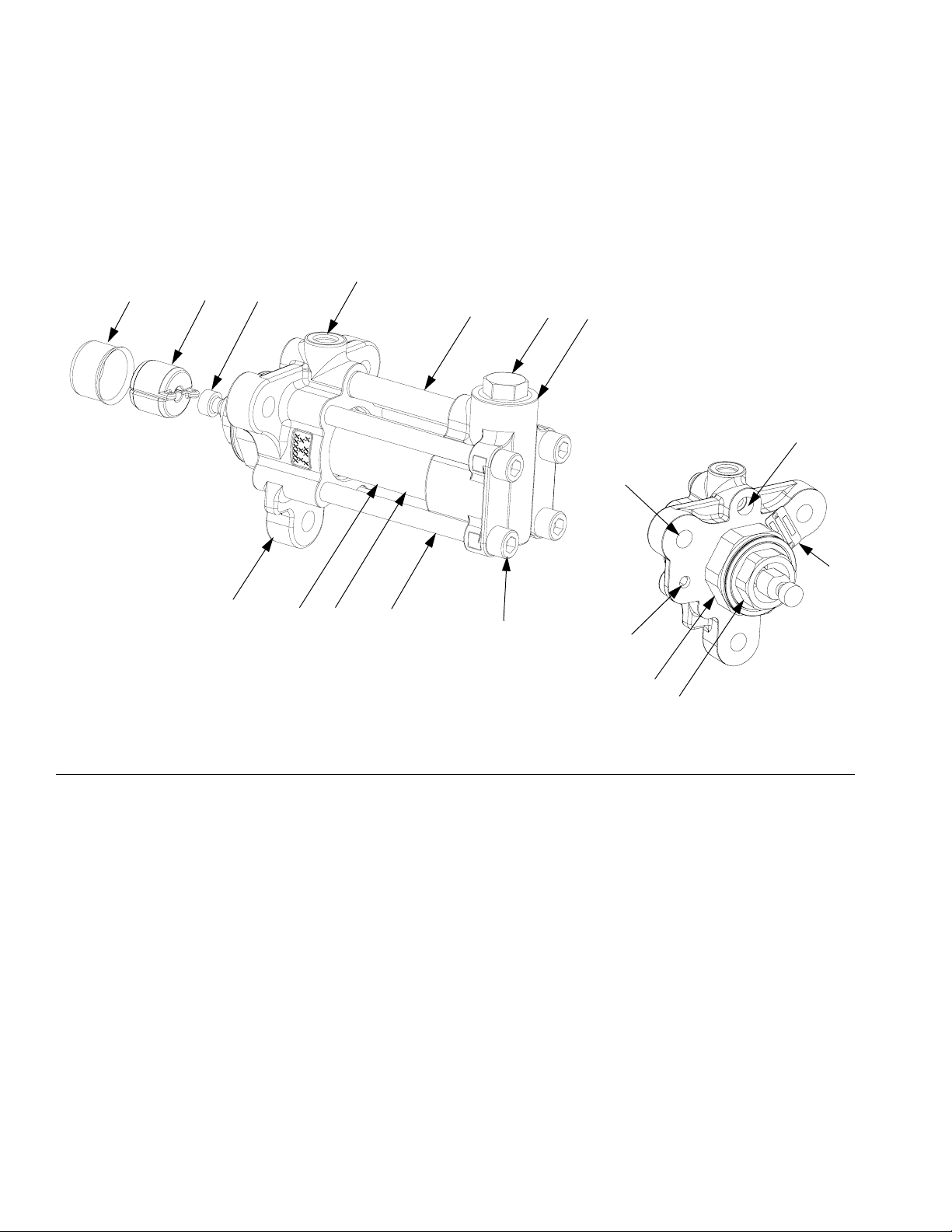
Component Identification
Component Identification
40cc pump shown
K
TU
S
F
HJ
Outlet Housing (D)
N
M
D
A
FIG. 1: Component Identification
Key:
A Displacement Rod (inside main cylinder)
B Throat Retainer
C Throat Cartridge
D Outlet Housing
E Main Cylinder
F Crossover Tube
GTie Bolt
H Inlet Housing
JInlet Cap
K Fluid Outlet
L Fluid Inlet (bottom of inlet housing)
M Pump Mounting Holes
N Pressure Transducer Port
P Linear Transducer Mounting Hole
R Identification Tag
S Rod Adapter (not on all models)
T Pump Coupler
U Coupler Cover
r_257891_3a0019_2h
R
E
G
L
P
C
r_257891_3a0019_3h
B
6 3A0019J
Page 7

Pressure Relief Procedure
Pressure Relief
Procedure
Trapped air can cause the pump to cycle unexpectedly, which could result in serious injury from splashing or moving parts.
1. Select Park on Pump Control Switch if available, or
turn off.
2. Turn off feed pumps.
3. Trigger gun to relieve pressure.
4. Close gun inlet valves.
5. Close fluid supply inlet valves.
6. Open all fluid drain valves in the system, having a
waste container ready to catch drainage. Leave
drain valve(s) open until you are ready to spray
again.
Flushing
Flush equipment only in a well-ventilated area. Do not
spray flammable fluids. Do not turn on heaters while
flushing with flammable solvents.
• Flush with a fluid that is compatible with the fluid
being dispensed and the equipment wetted parts.
• Flush out old fluid with new fluid, or flush out old
fluid with a compatible solvent before introducing
new fluid.
• Use lowest possible pressure when flushing.
7. If you suspect the spray tip or hose is clogged or
that pressure has not been fully relieved after following the steps above, VERY SLOWLY loosen tip
guard retaining nut or hose end coupling to relieve
pressure gradually, then loosen completely. Clear
hose or tip obstruction.
3A0019J 7
Page 8
Repair
Repair
Required Tools
• Large vise
• Set of adjustable wrenches
• O-ring pick
• 1/2 in. bit socket
• Rubber mallet
• Torque wrench
• 2 in. and 3 in. sockets
• Anti-seize lubricant
• Removable strength thread locker
Inlet Housing Disassembly
1. Relieve pressure and flush system. See Pressure
Relief Procedure and Flushing, page 7.
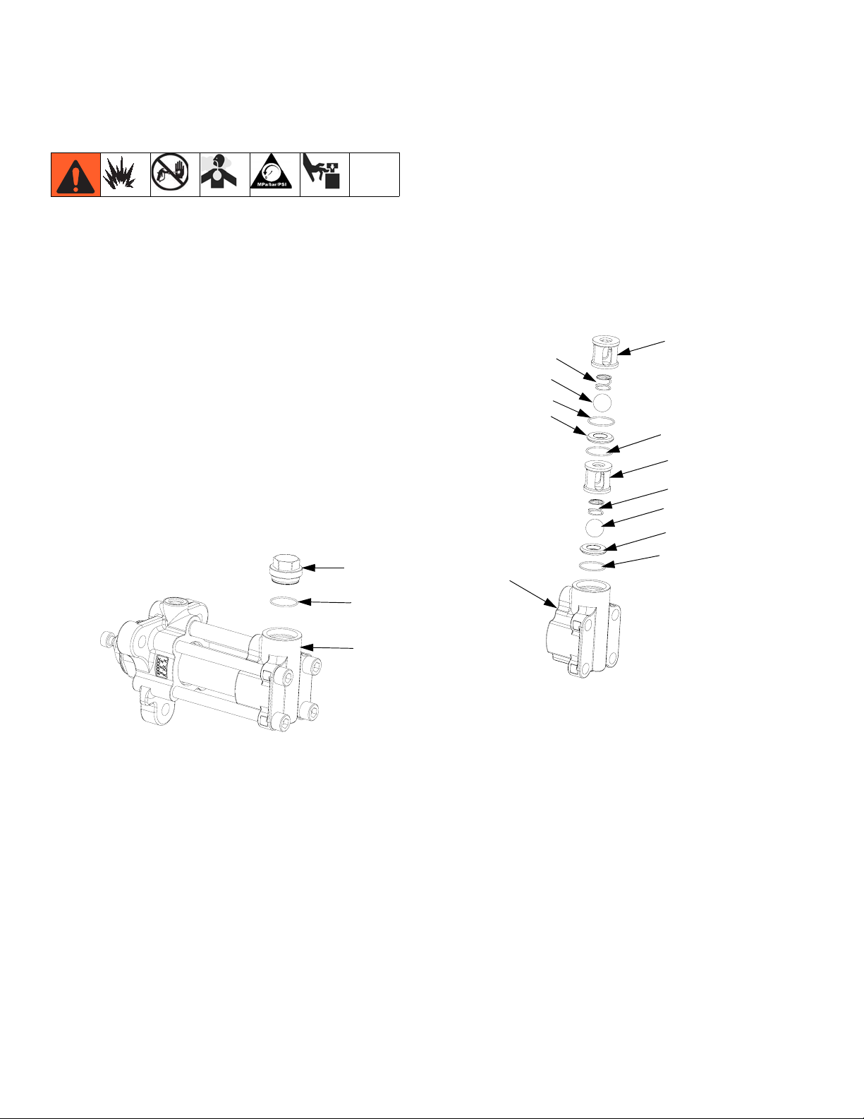
2. Remove inlet hose and drain inlet housing (7).
13
a. Remove upper ball cage (12), spring (11), ball
(10), o-ring (8) and seat (9).
b. Press lower ball (10) off seat (9) from fluid inlet
and drain the inlet housing (7).
c. Remove o-ring (8), lower ball cage (12), spring
(11), ball (10), seat (9), and o-ring (8).
11
10
8
9
6
12
8
12
11
10
9
8
8
6
r_257891_3a0019_4h
3. Remove inlet cap (13) from inlet housing (6), and
remove o-ring (8).
r_257891_3a0019_5h
d. Clean all parts in a compatible solvent. Lay
them in order for easier reassembly. Inspect
each ball and seat for nicks or scratches;
replace as required.
Inlet Housing Assembly
1. Install inlet housing components in inlet housing (6).
2. Install o-ring (8) on inlet cap (13) and apply
anti-seize lubricant to inlet cap (13) threads. Fully
tighten inlet cap (13) with a wrench.
8 3A0019J
Page 9

Repair
Pump Disassembly
1. Relieve pressure and flush system. See Pressure
Relief Procedure and Flushing, page 7.
2. Remove inlet hose and drain inlet housing (7).
3. Horizontally clamp pump on outlet housing (7) in
vise, use 1/2 in. hex bit socket to loosen all four tie
bolts (5) from inlet housing (6).
clamp here
21
4. For 40cc and 50cc pumps only: Use wrench to
remove rod adapter (21).
5. Remove pump assembly from vise and lay on a flat
surface with towels or in catch pan.
clamp here
6
5
7
r_257891_3a0019_6h
7. Remove inlet housing (6) from main cylinder (3).
Remove crossover tube (4) and o-rings (2).
2
4
6
2
21
15
3
r_257891_3a0019_7h
8. Pull main cylinder (3) and displacement rod (15)
away from outlet housing (7).
NOTICE
Be careful not to scratch the displacement rod (15);
place it on a smooth working surface. Damage to the
displacement rod will shorten pump life.
9. Remove displacement rod (15) from cylinder (3).
3
6. Fully unthread and remove tie bolts (5).
5
6
r_257891_3a0019_30h
15
r_257891_3a0019_8h
10. Remove two o-rings (1) from main cylinder (3).
1
1
3
r_257891_3a0019_9h
11. Place outlet housing (7) in vise so throat cartridge
(18) is facing up.
3A0019J 9
Page 10

Repair
12. Remove throat retainer (19).
16 or 25
19
17 or 26
7
18
20
r_257891_3a0019_10h
13. Use screwdriver and carefully press bearing (16 or
25) and u-cup (17 or 26) out of outlet housing (7).
NOTICE
To prevent damage to seals, carefully press seals
with a screwdriver.
14. If o-ring (20) is leaking, remove throat cartridge (18)
and o-ring (20).
15. Clamp flats on seal end of displacement rod (15) in
vise. Remove piston retainer (14), bearing (16), and
u-cup (17).
For 5cc, 10cc, and 15cc pumps
17
16
14
15
For 20cc-50cc pumps
17
16
14
15
For 60cc-160cc pumps
17
16
14
15
16. Thoroughly clean all metal parts in a compatible solvent.
10 3A0019J
Page 11

Repair
Pump Assembly
NOTICE
To prevent cross-contamination of the equipment’s
wetted parts, never interchange component A (isocyanate) and component B (resin) parts.
NOTICE
To prevent damage to seals always use piston
assembly tool (PT) and rod installation tool (RT) from
repair kit when assembling the piston seals and displacement rod.
NOTE: Piston assembly tool is NOT needed for
10cc-15cc pump sizes.
1. Install piston seal installation tool (PT) from pump
repair kit on displacement rod (15). Hand tighten.
2. Apply grease to seal and bearing surface of displacement rod (15).
3. Install u-cup (17) and bearing (16). Ensure u-cup
springs face displacement rod. Remove piston seal
installation tool (PT).
4. For 20cc-50cc pumps: Apply one stripe of removable strength thread locker to displacement rod (15)
male threads and install piston retainer (14).
NOTICE
Specification sheets and Graco testing indicate that
anaerobic sealant requires three days to fully cure.
Failure to allow three days for full cure may result in
parts coming loose during operation. If faster cure
time is needed, Rapid Sealant Cure Kit is available,
24N985.
17
16
15
PT
14
5. For 5cc, 10cc, 15cc, and 60cc-160cc pumps: Apply
one stripe of removable strength thread locker to
piston retainer (14) threads and assemble.
NOTICE
Specification sheets and Graco testing indicate that
anaerobic sealant requires three days to fully cure.
Failure to allow three days for full cure may result in
parts coming loose during operation. If faster cure
time is needed, Rapid Sealant Cure Kit is available,
24N985.
5cc, 10cc, and 15cc pumps
17
16
14
15
60cc-160cc pumps
16
14
15
PT
17
NOTICE
To prevent displacement rod damage, do not clamp
directly onto displacement rod surface.
6. Clamp flats on seal end of displacement rod (15) in
vise. See Torque Specification table for piston
retainer (14) torque according to pump size.
Pump Size Torque
5cc 38 in-lbs (3.2 ft-lbs) (4.3 N•m)
10cc 5.5 ft-lbs (7.4 N•m)
15cc 5.5 ft-lbs (7.4 N•m)
20cc 30 ft-lbs (40.6 N•m)
25cc 30 ft-lbs (40.6 N•m)
30cc 30 ft-lbs (40.6 N•m)
40cc 50 ft-lbs (67.5 N•m)
50cc 50 ft-lbs (67.5 N•m)
60cc 80 ft-lbs (108 N•m)
65cc 80 ft-lbs (108 N•m)
75cc 80 ft-lbs (108 N•m)
80cc 80 ft-lbs (108 N•m)
86cc 80 ft-lbs (108 N•m)
100cc 160 ft-lbs (216 N•m)
120cc 160 ft-lbs (216 N•m)
160cc 160 ft-lbs (216 N•m)
3A0019J 11
Page 12

Repair
7. If the throat cartridge (18) was removed, install
o-ring (20) on throat cartridge (18) and lubricate
with grease. Apply anti-seize lubricant to throat cartridge (18) threads and install in outlet housing (7).
Fully tighten throat cartridge (18) with a wrench.
8. Apply grease to u-cup (17 or 26) and set in throat
cartridge (18); ensure u-cup springs face throat cartridge. Set bearing (16 or 25) on top of u-cup (17 or
26).
19
15
16 or 25
17 or 26
7
RT
18
20
r_257891_3a0019_10h
2
4
2
1
1
3
r_257891_3a0019_15h
16. Install main cylinder (3) and crossover tube (4) in
outlet housing (7) with a rubber mallet.
4
3
7
9. Apply anti-seize lubricant to throat retainer (19)
threads and place on throat cartridge (18) above
bearing (16 or 25).
NOTE: Do not thread retainer(19) into throat cartridge (18).
10. Install rod installation tool (RT) on displacement rod
(15). Insert the displacement rod (15) through the
throat retainer (19), bearing (16 or 25), and u-cup
(17 or 26).
NOTE: The displacement rod (15) guides the bearing
(16 or 25) and u-cup (17 or 26) into the throat cartridge bore (18).
11. By hand, thread throat retainer (19) into throat cartridge (18) to gradually press bearing (16 or 25) and
u-cup (17 or 26) into bore.
12. When fully engaged, torque throat retainer (19) to
50 ft-lbs (67.5 N•m).
13. Remove displacement rod (15).
14. Clamp throat cartridge (18) in vise with outlet housing (7) facing up.
r_257891_3a0019_16h
17. Lubricate piston u-cup seal (17), and bearing (16)
with grease.
18. For 60cc-160cc pumps: Apply grease to coupler end
of displacement rod (15) before installing the rod
installation tool (RT).
NOTE: The grease will hold the rod installation tool
(RT) in place while assembling the displacement rod
into the cylinder.
19. Install rod installation tool (RT) on displacement rod
(15).
15. Install o-rings (1) on main cylinder (3) and o-rings
(2) on crossover tube (4). Lubricate o-rings (1, 2)
with grease.
12 3A0019J
Page 13

Repair
20. Install displacement rod (15) in main cylinder (3)
and throat cartridge (18). Gently tap displacement
rod with a rubber mallet until piston is flush or below
the surface of the main cylinder.
16
17
15
18
RT
r_257891_3a0019_17h
23. Lubricate tie bolt (5) threads and install. Tighten tie
bolts evenly in a star pattern until they are flush with
the inlet housing (6).
24. Tighten tie bolts (5) evenly in a star pattern to the
outlet housing (7). Ensure the inlet housing is evenly
seated onto the main cylinder (3) and crossover
tube (4). Torque tie bolts (5) evenly to 50-200 ft-lbs
(60-270 N•m), all to the same torque value.
3
25. For 10cc-50cc pumps only: Clean rod adapter (21)
threads with a wire brush and apply removable
strength thread locker to displacement rod (15)
threads. Install rod adapter (21) on displacement
rod (15). See Torque Specification table for rod
adapter (21) torque according to pump size.
Pump Size Torque
5cc 38 in-lbs (3.2 ft-lbs) (4.3 N•m)
10cc 8.5 ft-lbs (11.5 N•m)
15cc 8.5 ft-lbs (11.5 N•m)
20cc 30 ft-lbs (40.6 N•m)
25cc 30 ft-lbs (40.6 N•m)
30cc 30 ft-lbs (40.6 N•m)
40cc 45 ft-lbs (60.75 N•m)
50cc 45 ft-lbs (60.75 N•m)
21. Remove rod installation tool (RT).
22. Gently place inlet housing (6) on main cylinder (3)
and crossover tube (4).
NOTICE
To prevent damage to o-rings, do not press inlet
housing down on main cylinder and crossover tube.
6
5
4
3
15
21
r_257891_3a0019_19h
3A0019J 13
Page 14

Parts
Parts
5cc, 10cc, and 15cc Pumps
35
34
21
4
19
3
9
33
26
25
10
8
18
6
9
13
96
8
12
20
11
10
8
9
2
4
2
2
8
12
11
10
9
2
8
1
3
7
1
15
17
12
11
1. Lubricate seals, o-rings, lead-in’s and moving parts with
grease.
2
Apply one stripe of removable strength anaerobic sealant on
threads.
NOTICE
Specification sheets and Graco testing indicate that anaerobic sealant requires three days to fully cure. Failure to
allow three days for full cure may result in parts coming
loose during operation.
If faster cure time is needed,
Rapid Sealant Cure Kit is available, 24N985.
3
Torque to 50-ft-lbs (67.5 N•m).
4
Assemble and torque after displacement rod (15) is assembled
through throat retainer (19). See table on page 13 for torque
specification.
12
16
14
7
6
r_257886_3a0019_1d
5
5
5
Torque evenly to 50-200 ft-lbs (60-270 N•m), all to the same
torque value.
6
Fully tighten with a wrench.
7
See table on page 11 for torque specification.
8
Must be pressed straight into housing.
9
Apply anti-seize lubricant to threads.
10
Ensure u-cup (26) springs face throat cartridge (18).
11
Ensure u-cup (17) springs face displacement rod (15).
12
Fully assemble seal (17) and bearing (16) onto displacement
rod (15) before tightening piston retainer (14).
14 3A0019J
Page 15

20cc, 25cc, 30cc, 40cc, and 50cc Pumps
35
34
19
3
9
33
25
26
Parts
6
9
10
8
13
96
18
20
4
21
25
11
10
8
8
12
9
2
4
2
2
2
8
12
11
10
9
8
1
7
3
1
15
17
12
11
16
12
14
7
6
5
5
r_257891_3a0019_20h
1. Lubricate seals, o-rings, lead-in’s and moving parts with
grease.
2
Apply one stripe of removable strength anaerobic sealant on
threads.
NOTICE
Specification sheets and Graco testing indicate that anaerobic sealant requires three days to fully cure. Failure to
allow three days for full cure may result in parts coming
loose during operation.
If faster cure time is needed,
Rapid Sealant Cure Kit is available, 24N985.
3
Torque to 50-ft-lbs (67.5 N•m).
4
Assemble and torque after displacement rod (15) is assembled
through throat retainer (19). See table on page 13 for torque
specification.
5
Torque evenly to 50-200 ft-lbs (60-270 N•m), all to the same
torque value.
6
Fully tighten with a wrench.
7
See table on page 11 for torque specification.
8
Must be pressed straight into housing.
9
Apply anti-seize lubricant to threads.
10
Ensure u-cup (26) springs face throat cartridge (18).
11
Ensure u-cup (17) springs face displacement rod (15).
12
Fully assemble seal (17) and bearing (16) onto displacement
rod (15) before tightening piston retainer (14).
3A0019J 15
Page 16

Parts
60cc, 65cc, 75cc, 80cc, 86cc, 100cc, 120cc, and 160cc Pumps
35
34
19
3
9
17
16
10
8
18
96
20
6
9
13
8
11
12
10
8
9
2
4
2
8
12
11
10
9
8
1
7
3
1
15
17
12
11
12
16
2
1. Lubricate seals, o-rings, lead-in’s and moving parts with
grease.
2
Apply one stripe of removable strength anaerobic sealant on
threads.
NOTICE
Specification sheets and Graco testing indicate that anaerobic sealant requires three days to fully cure. Failure to
allow three days for full cure may result in parts coming
loose during operation.
If faster cure time is needed,
Rapid Sealant Cure Kit is available, 24N985.
3
Torque to 50-ft-lbs (67.5 N•m).
5
Torque evenly to 50-200 ft-lbs (60-270 N•m), all to the same
torque value.
14
7
6
Fully tighten with a wrench.
7
See table on page 11 for torque specification.
8
Must be pressed straight into housing.
9
Apply anti-seize lubricant to threads.
10
Ensure u-cup (17) springs face throat cartridge (18).
11
Ensure u-cup (17) springs face displacement rod (15).
12
Fully assemble seal (17) and bearing (16) onto displacement
rod (15) before tightening piston retainer (14).
6
5
5
r_257893_3a0019_21h
16 3A0019J
Page 17

Parts
Pump Parts
Ref. Part Description Qty.
1✓✿✠◆❄ O-RING, cylinder 2
2✓✿✠◆❄ O-RING, crossover tube 2
3✿ CYLINDER, pump 1
4✠ TUBE, crossover, pump 1
5 258790 BOLT, tie 4
6 258792 HOUSING, inlet 1
7 258791 HOUSING, outlet 1
8◆† O-RING, inlet 4
258775 KIT, package of 4 -
258776 KIT, package of 16 9† SEAT, carbide 2
10† BALL, sst 2
11 258784 SPRING, ball check 2
12 258785 HOUSING, ball cage 2
13 258787 CAP, inlet valve 1
14*❄ RETAINER, piston 1
15❄ ROD, displacement 1
16◆❄ BEARING, piston 1(2)
17◆❄ SEAL, piston 1(2)
18★ CARTRIDGE, throat 1
19✖ RETAINER, throat 1
20★❄ 117286 O-RING, throat cartridge 1
21❄ 258786 ADAPTER, rod; 40cc and
50cc
258966 ADAPTER, rod; 10cc and
15cc
258967 ADAPTER, rod; 20cc-30cc 1
25◆❄ BEARING, throat 1
26◆❄ SEAL, throat 1
28 PLATE, identification 1
29 SCREW, drive 2
33‡ SPACER, throat; 10cc-30cc
only
34❖ 247167 COUPLER, pump;
10cc-80cc
244819 COUPLER, pump;
100cc-160cc
35 197340 COVER, coupler 1
✓ Refer to Table 1: Cylinder O-ring Kits for kit number.
✿ Refer to Table 2: Cylinder Kits for kit number.
✠ Refer to Table 3: Crossover Tube Kits for kit number.
★ Refer to Table 4: Throat Cartridge Kits for kit number.
✖ Refer to Table 5: Throat Retainer Kits for kit number.
* Refer to Table 6: Piston Retainer Kits for kit number.
◆ Refer to Table 7: Seal Kits for kit number.
❄ Refer to Table 8: Displacement Rod Kits for kit num-
ber.
‡ Refer to Table 9: Throat Spacer Kits for kit number.
† Included in Kit 258783.
❖ Clip coupler cable before installing on to proportioner
pumpline.
1
1
1
1
1
3A0019J 17
Page 18

Parts
Table 1: Cylinder O-ring Kits
Pump Size Cylinder O-ring Kit
5cc
10cc
15cc
20cc
25cc
30cc
40cc
50cc
60cc
65cc
75cc
80cc
86cc
100cc
120cc
160cc
258774
258773
Table 2: Cylinder Kits
Pump Size Cylinder Kit
Table 3: Crossover Tube Kits
Pump Size Bar Stock Inlet* Cast inlet*
5cc
10cc
15cc
20cc
25cc
30cc
40cc
50cc
60cc
65cc
75cc
80cc
86cc
100cc
160cc
*See figure below for inlet types
Bar Stock Inlet Cast Inlet
258789 24E557
258788 24E556120cc
5cc 262557
10cc 258925
15cc 258931
20cc 258937
25cc 258943
30cc 258949
40cc 258795
50cc 258801
60cc 258807
65cc 24H998
75cc 24N821
80cc 258813
86cc 24H999
100cc 258819
120cc 258825
160cc 258831
18 3A0019J
Page 19

Parts
Table 4: Throat Cartridge Kits
Pump Size Throat Cartridge Kit
5cc 262558
10cc 258928
15cc 258934
20cc 258940
25cc 258946
30cc 258952
40cc 258798
50cc 258804
60cc 258810
65cc 24J007
75cc 24N819
80cc 258816
86cc 24J008
100cc 258822
120cc 258828
160cc 258834
Table 6: Piston Retainer Kits
Pump Size Piston Retainer Kit
5cc 262560
10cc 258926
15cc 258932
20cc 258938
25cc 258944
30cc 258950
40cc 258796
50cc 258802
60cc 258808
65cc 24J012
75cc 24N822
80cc 258814
86cc 24J013
100cc 258820
120cc 258826
160cc 258832
Table 5: Throat Retainer Kits
Pump Size Throat Retainer Kit
5cc 262559
10cc 258927
15cc 258933
20cc 258939
25cc 258945
30cc 258951
40cc 258797
50cc 258803
60cc 258809
65cc 24J010
75cc 24N818
80cc 258815
86cc 24J011
100cc 258821
120cc 258827
160cc 258833
3A0019J 19
Page 20

Parts
Seal Kits
5cc-30cc Throat Seals
40cc-160cc Throat Seals
Piston Seals
33
25
26
25
26
17
16
Table 7: Seal Kits
Reference Number and Quantity Included in Kit
Pump Size Seal Kit 1 2 8 16 17 25 26
5cc
10cc
15cc
20cc
25cc
30cc
40cc
50cc
60cc
65cc
75cc
80cc
86cc
262561 2241111
258923 2241111
258929 2241111
258935 2241111
258941 2241111
258947 2241111
258793 2241111
258799 2241111
258805 22422
24J00222422
24N82022422
258811 22422
24J00322422
100cc
120cc
160cc
20 3A0019J
258817 22422
258823 22422
258829 22422
Page 21

Displacement Rod Kits
16
17
15
60cc Displacement Rod Shown
16
17
14
Parts
40cc Displacement Rod Shown
16
33
25
26
25
26
15
10cc Displacement Rod Shown
16
14
17
17
14
3A0019J 21
Page 22

Parts
Table 8: Displacement Rod Kits
Reference Number and Quantity Included in Kit
Pump Size
5cc
10cc
15cc
20cc
25cc
30cc
40cc
50cc
60cc
65cc
75cc
80cc
86cc
100cc
Displacement
Rod Kit
262562 2 2 1 1 1 1 1 1 1 1
258924 2 2 1 1 1 1 1 1 1 1
258930 2 2 1 1 1 1 1 1 1 1
258936 2 2 1 1 1 1 1 1 1 1
258942 2 2 1 1 1 1 1 1 1 1
258948 2 2 1 1 1 1 1 1 1 1
258794 2 2 1 1 1 1 1 1 1 1
258800 2 2 1 1 1 1 1 1 1 1
258806 2 2 1 1 2 2 1
24J004 2211221
24N823 2211221
258812 2 2 1 1 2 2 1
24J005 2211221
258818 2 2 1 1 2 2 1
1 2 14 15 16 17 20 21 25 26
120cc
160cc
258824 2 2 1 1 2 2 1
258830 2 2 1 1 2 2 1
Table 9: Throat Spacer Kits
Pump Size Throat Spacer Kit
5cc
10cc
15cc
20cc
25cc
30cc
16E364
16D188
16D189
16D190
16D191
16D192
22 3A0019J
Page 23

Dimensions
All pump sizes have the same dimensions.
C
Dimensions
A
A
(Length)
in. (mm)
13.36 (339.34) 3/4-14 3/4-16
B
(Inlet)
in. npt (f)
C
(Outlet)
SAE (f)
r_257891_3a0019_22h
B
3A0019J 23
Page 24

Outlet Housing Mounting Hole Layout
Outlet Housing Mounting Hole Layout
All pumps have the same outlet housing mounting hole layout.
5.9 in (150 mm)
r_257891_3a0019_23h
24 3A0019J
Page 25

Technical Data
Technical Data
Maximum working pressure . . . . . . . . . . . . . . . . . . . . . . . 3500 psi (24MPa, 241 bar)
Maximum operating temperature . . . . . . . . . . . . . . . . . . . 180° F (82° C)
Maximum cycle rate . . . . . . . . . . . . . . . . . . . . . . . . . . . . . 65 cycles per minute
Minimum feed pressure at inlet . . . . . . . . . . . . . . . . . . . . 50 psi (0.35 MPa, 3.5 bar)
Weight . . . . . . . . . . . . . . . . . . . . . . . . . . . . . . . . . . . . . . . 30 lbs (13.6 kg)
Wetted parts . . . . . . . . . . . . . . . . . . . . . . . . . . . . . . . . . . . SST, tungsten carbide, acetal, PTFE, UHMWPE
3A0019J 25
Page 26

Graco Standard Warranty
Graco warrants all equipment referenced in this document which is manufactured by Graco and bearing its name to be free from defects in
material and workmanship on the date of sale to the original purchaser for use. With the exception of any special, extended, or limited warranty
published by Graco, Graco will, for a period of twelve months from the date of sale, repair or replace any part of the equipment determined by
Graco to be defective. This warranty applies only when the equipment is installed, operated and maintained in accordance with Graco’s written
recommendations.
This warranty does not cover, and Graco shall not be liable for general wear and tear, or any malfunction, damage or wear caused by faulty
installation, misapplication, abrasion, corrosion, inadequate or improper maintenance, negligence, accident, tampering, or substitution of
non-Graco component parts. Nor shall Graco be liable for malfunction, damage or wear caused by the incompatibility of Graco equipment with
structures, accessories, equipment or materials not supplied by Graco, or the improper design, manufacture, installation, operation or
maintenance of structures, accessories, equipment or materials not supplied by Graco.
This warranty is conditioned upon the prepaid return of the equipment claimed to be defective to an authorized Graco distributor for verification of
the claimed defect. If the claimed defect is verified, Graco will repair or replace free of charge any defective parts. The equipment will be returned
to the original purchaser transportation prepaid. If inspection of the equipment does not disclose any defect in material or workmanship, repairs will
be made at a reasonable charge, which charges may include the costs of parts, labor, and transportation.
THIS WARRANTY IS EXCLUSIVE, AND IS IN LIEU OF ANY OTHER WARRANTIES, EXPRESS OR IMPLIED, INCLUDING BUT NOT LIMITED
TO WARRANTY OF MERCHANTABILITY OR WARRANTY OF FITNESS FOR A PARTICULAR PURPOSE.
Graco’s sole obligation and buyer’s sole remedy for any breach of warranty shall be as set forth above. The buyer agrees that no other remedy
(including, but not limited to, incidental or consequential damages for lost profits, lost sales, injury to person or property, or any other incidental or
consequential loss) shall be available. Any action for breach of warranty must be brought within two (2) years of the date of sale.
GRACO MAKES NO WARRANTY, AND DISCLAIMS ALL IMPLIED WARRANTIES OF MERCHANTABILITY AND FITNESS FOR A
PARTICULAR PURPOSE, IN CONNECTION WITH ACCESSORIES, EQUIPMENT, MATERIALS OR COMPONENTS SOLD BUT NOT
MANUFACTURED BY GRACO. These items sold, but not manufactured by Graco (such as electric motors, switches, hose, etc.), are subject to
the warranty, if any, of their manufacturer. Graco will provide purchaser with reasonable assistance in making any claim for breach of these
warranties.
In no event will Graco be liable for indirect, incidental, special or consequential damages resulting from Graco supplying equipment hereunder, or
the furnishing, performance, or use of any products or other goods sold hereto, whether due to a breach of contract, breach of warranty, the
negligence of Graco, or otherwise.
FOR GRACO CANADA CUSTOMERS
The Parties acknowledge that they have required that the present document, as well as all documents, notices and legal proceedings entered into,
given or instituted pursuant hereto or relating directly or indirectly hereto, be drawn up in English. Les parties reconnaissent avoir convenu que la
rédaction du présente document sera en Anglais, ainsi que tous documents, avis et procédures judiciaires exécutés, donnés ou intentés, à la suite
de ou en rapport, directement ou indirectement, avec les procédures concernées.
Graco Information
For the latest information about Graco products, visit www.graco.com.
TO PLACE AN ORDER, contact your Graco distributor or call to identify the nearest distributor.
Toll Free: 1-800-746-1334 Fax: 330-966-3006
All written and visual data contained in this document reflects the latest product information available at the time of publication.
GRACO INC. AND SUBSIDIARIES • P.O. BOX 1441 • MINNEAPOLIS MN 55440-1441 • USA
Copyright 2009, Graco Inc. All Graco manufacturing locations are registered to ISO 9001.
Graco reserves the right to make changes at any time without notice.
For patent information, see www.graco.com/patents.
Original instructions. This manual contains English. MM 3A0019
Graco Headquarters: Minneapolis
International Offices: Belgium, China, Japan, Korea
www.graco.com
Revised July 2012
 Loading...