

Page 1
INSTRUCTIONS-PARTS LIST
LineLazert III 3900 and 5900
Airless Paint Stripers
3300 psi (228 bar, 22.8 MPa) Maximum Working Pressure
309414J
LineLazer III 3900
Model Series Description
233688 A Striper with one Gun
233689 A Striper with Second Gun Kit
233664 A International Striper with one Gun
233694 A International Striper with 2nd Gun Kit
LineLazer III 5900
Model Series Description
233690 A Striper with one Gun
233691 A Striper with Second Gun Kit
233627 A International Striper with one Gun
233695 A International Striper with 2nd Gun Kit
Important Safety Instructions
Read all warnings and instructions in this manual.
Save these instructions.
ENG
233688
ti1935a
Related Manuals
Operator 309413...........................
Displacement Pump 309277.................
Spray Gun 309093.........................
Spray Tip *.................................
PC Board 309459..........................
Drain Valve Kit 308961......................
Clutch Replacement Kit 309890..............
* for spray tip selection, see page 4
Table of Contents
Warnings and Cautions 2.........................
Spray Tip Selection Table 3........................
Maintenance 4...................................
Troubleshooting 5................................
Repair
Bearing Housing & Connecting Rod 8.............
Drive Housing 9................................
Engine 10.....................................
Pressure Control 13............................
GRACO INC. P.O. BOX 1441 MINNEAPOLIS, MN 55440--1441
ECOPYRIGHT 2002, GRACO INC.
Graco Inc. is registered to I.S. EN ISO 9001
Displacement Pump 15.........................
Pinion and Drive Housing Assemblies 16..........
Parts
LineLazer III 3900/5900 18......................
Pressure Control 24............................
Dimensions 29...................................
Technical Data 29................................
Graco Phone Number 29..........................
Graco Warranty 30...............................
Page 2
Warnings and Cautions
Warning Symbol
WARNING
This symbol alerts you to the possibility of serious
injury or death if you do not follow the instructions.
WARNING
Fire and explosion hazard: Solvent and paint fumes can ignite
or explode.
To help prevent a fire and explosion:
DUse only in an extremely well ventilated area.
DEliminate all ignition sources; such as pilot lights, cigarettes and
plastic drop cloths (static arc hazard). Do not plug or unplug
power cords or turn lights on or off in spray area.
DGround Sprayer, object being sprayed, paint and solvent pails.
DHold gun firmly to side of grounded pail when triggering into pail.
DUse only conductive airless paint hose.
DDo not use 1,1,1-trichloroethane, methylene chloride, other
halogenated hydrocarbon solvents or fluids containing such
solvents in pressurized aluminum equipment. Such use could
result in a chemical reaction, with the possibility of explosion.
DDo not fill fuel tank while engine is running or hot.
DDo not flush with gasoline.
Caution Symbol
CAUTION
This symbol alerts you to the possibility of damage to
or destruction of equipment if you do not follow the
instructions.
Fluid injection and high pressure hazard: High pressure spray
or leaks can inject fluid into the body.
To help prevent injection, always:
DEngage trigger safety latch when not spraying.
DKeep clear of nozzle and leaks.
DNever spray without a tip guard.
DDo PRESSURE RELIEF if you stop spraying or begin servicing
spraye r.
DDo not use components rated less than sprayer Maximum
Working Pressure.
DNever allow children to use this unit.
If high pressure fluid pierces your skin, the injury might look
like “just a cut”. But it is a serious wound! Get immediate surgical
treatment.
3094142
Page 3

Spray Tip Selection Table
LineLazer Tip Selection Guide. Sprayer is supplied with tip LL5319. For additional applications, use the tip selec-
tion table as follows:
Note: the last three digits (LL5319
For example: the line width for tip LL5319 is 4 in. as shown in the table below. The tip orifice for tip LL5319
LineLazer Tip Selection Table
Tip Size
221203* 2 inches Sport court -- light film build
LL5213* 2 inches Sport court -- heavy film build
LL5215* 4 inches Alkyd paints only -- light film build
LL5217 4 inches Alkyd paints only -- medium film build
LL5219 4 inches Alkyd paints only -- heavy film build
LL5315 4 inches Most traffic paints -- light film build
LL5317 4 inches Most traffic paints -- medium film build
LL5319 4 inches Most traffic paints -- medium film build
LL5321 4 inches Most traffic paints -- heavy film build
LL5323 4 inches Most traffic paints -- heavy film build
LL5327† 4 inches Most traffic paints -- heavy film build
LL5417# 4 -- 8 inches All paints and high solids traffic paints -- light film build
LL5419# 4 -- 8 inches All paints and high solids traffic paints -- medium film build
LL5421# 4 -- 8 inches All paints and high solids traffic paints -- heavy film build
LL5621 8 -- 12 inches All traffic paints -- light film build
LL5623 8 -- 12 inches All traffic paints -- medium film build
LL5625 8 -- 12 inches All traffic paints -- medium film build
LL5627 8 -- 12 inches All traffic paints -- heavy film build
Line Width Used For
) of the tip part number identifies the line width and tip orifice (opening).
is .019 in.
* May require 100 mesh filter to minimize tip plugging.
† Best for use with LineDriver.
# Best for cold weather applications.
How to Maximize Line Quality and Reduce Tip Wear. Observe the following suggestions to increase line quality
and minimize sprayer tip wear.
1. Select a larger tip orifice and run the sprayer at a reduced operating pressure.
2. Running larger tip sizes (example: use tip LL5321 @ 2000 psi instead of LL5317 @ 3300 psi) will significantly
increase tip life and reduce tip plugging. It will also produce a more uniform film build across the line.
309414 3
Page 4
WARNING
Maintenance
DAILY: Check pressure drain valve for proper opera-
tion.
INJECTION HAZARD
The system pressure must be manually
relieved to prevent the system from
starting or spraying accidentally. Fluid
under high pressure can be injected through the
skin and cause serious injury. To reduce the risk of
an injury from injection, splashing fluid, or moving
parts, follow the Pressure Relief Procedure
whenever you:
D areinstructedtorelievethepressure,
D stop spraying,
D check or service any of the system equipment,
D or install or clean the spray tip.
Pressure Relief Procedure
1. Lock gun trigger safety.
2. Turn engine ON/OFF switch to OFF.
3. Move pump switch to OFF and turn pressure
control knob fully counterclockwise.
4. Unlock trigger safety. Hold metal part of gun firmly
to side of grounded metal pail, and trigger gun to
relieve pressure.
DAILY: Check and fill the gas tank.
AFTER THE FIRST 20 HOURS OF OPERA TION:
Drain engine oil and refill with clean oil. Reference
Honda Engines Owner’s Manual for correct oil viscosity.
WEEKLY: Remove air filter cover and clean element.
Replace element, if necessary. If operating in an
unusually dusty environment: check filter daily and
replace, if necessary.
Repack connecting rod (22) top needle bearing after
every pump change.
Replacement elements can be purchased from your
local HONDA dealer.
WEEKLY: Check level of TSL in displacement pump
packing nut. Fill nut, if necessary. Keep TSL in nut to
help prevent fluid buildup on piston rod and premature
wear of packings.
AFTER EACH 100 HOURS OF OPERATION:
Change engine oil. Reference Honda Engines Owner’s
Manual for correct oil viscosity.
5. Lock gun trigger safety.
6. Open pressure drain valve. Leave valve open until
ready to spray again.
If you suspect that the spray tip or hose is completely
clogged, or that pressure has not been fully relieved
after following the steps above, VERY SLOW LY
loosen tip guard retaining nut or hose end coupling to
relieve pressure gradually, then loosen completely.
Now clear tip or hose.
CAUTION
For detailed engine maintenance and specifications,
refer to separate Honda Engines Owner’s Manual,
supplied.
DAILY: Check engine oil level and fill as necessary.
DAILY: Check hose for wear and damage.
DAILY: Check gun safety for proper operation.
SPARK PLUG : Use only BPR6ES (NGK) or
W20EPR--U (NIPPONDENSO) plug. Gap plug to
0.028 to 0.031 in. (0.7 to 0.8 mm). Use spark plug
wrench when installing and removing plug.
Caster Wheel
(See letter call-outs in Parts drawing on page 22)
1. Once each year, tighten nut (164m) until spring
washer bottoms out. Then back off the nut 1/2 to
3/4 turn.
2. Once each year, tighten nut (62) until it begins to
compress spring washer. Then tighten the nut an
additional 1/4 turn.
3. Once each month, grease the wheel bearing (F).
4. Check pin (164e) for wear. If pin is worn out, there
will be play in the caster wheel. Reverse or replace the pin as needed.
5. Check caster wheel alignment as necessary.
To align: loosen bolt (164t), align wheel and tighten
bolt (164t).
3094144
Page 5
Troubleshooting
Relieve pressure; page 4.
PROBLEM CAUSE SOLUTION
E=XX is displayed Fault condition exists Determine fault correction from table, page 14.
Engine won’t start Engine switch is OFF Turn engine switch ON
Engine is out of gas Refill gas tank. Honda Engines Owner’s Manual.
Engine operates, but displacement pump does not
operate
Engine oil level is low Try to start engine. Replenish oil, if necessary.
Spark plug cable is disconnected or damaged Connect spark plug cable or replace spark
Cold engine Use choke
Fuel shutoff lever is OFF Move lever to ON position
Oil is seeping into combustion chamber Remove spark plug. Pull starter 3 to 4 times.
Error code displayed? Reference pressure control repair. Page 13.
Pump switch is OFF TurnpumpswitchON.
Pressure setting is too low Turn pressure adjusting knob clockwise to
Fluid filter (318) is dirty Clean filter. Page 24.
Tip or tip filter is clogged Clean tip or tip filter. Manual 309091.
Displacement pump piston rod is stuck due to
dried paint
Connecting rod is worn or damaged Replace connecting rod. Page 8.
Honda Engines Owner’s Manual.
plug
Clean or replace spark plug. Start engine.
Keep sprayer upright to avoid oil seepage.
increase pressure.
Repair pump. Manual 309277.
Drive housing is worn or damaged Replace drive housing. Page 9.
Electrical power is not energizing clutch field Check wiring connections. Page 10.
Reference pressure control repair. Page 13.
Reference wiring diagram. Page 28.
With pump switch ON and pressure turned to
MAXIMUM, use a test light to check for power
between clutch test points on control board.
Remove 7--pin connector from control board
and measure resistance across clutch coil. At
70_ F, the resistance must be between 1.2
±0.2Ω (LineLazer III 3900); 1.7 ±0.2Ω (Line-
Lazer III 5900); if not, replace pinion housing.
Have pressure control checked by authorized
Graco dealer.
Clutch is worn, damaged, or incorrectly
positioned
Pinion assembly is worn or damaged Repair or replace pinion assembly. Manual
Replace clutch. Manual 309890.
309890.
309414 5
Page 6

Troubleshooting
load
PROBLEM CAUSE SOLUTION
Pump output is low
Strainer (31) is clogged Clean strainer. Sprayer 233716 strainer is for
Piston ball (206) is not seating Service piston ball. Manual 309277.
Piston packings are worn or damaged Replace packings. Manual 309277.
O-ring (227) in pump is worn or damaged Replace o-ring. Manual 309277.
Intake valve ball is not seating properly Clean intake valve. Manual 309277.
Intake valve ball is packed with material Clean intake valve. Manual 309277. Do not
Engine speed is too low Increase throttle setting. Manual 309413.
Clutch is worn or damaged Replace clutch. Manual 309890.
Pressure setting is too low Increase pressure. Manual 309413.
Fluid filter (318), tip filter or tip is clogged or
dirty
Large pressure drop in hose with heavy
materials
use in paint only.
leave 233716 sprayer under pressure for more
than 5 minutes when spraying texture and not
actively spraying.
Clean filter. Manual 309413 or 309093.
Use larger diameter hose and/or reduce overall
length of hose. Use of more than 100 ft of 1/4
in. hose significantly reduces performance of
sprayer. Use 3/8 in. hose for optimum performance (50 ft minimum).
Excessive paint leakage into
throat packing nut
Fluid is spitting from gun
Pump is difficult to prime
Throat packing nut is loose Remove throat packing nut spacer. Tighten
throat packing nut just enough to stop leakage.
Throat packings are worn or damaged Replace packings. Manual 309277.
Displacement rod is worn or damaged Replace rod. Manual 309277.
Air in pump or hose Check and tighten all fluid connections.
Reprime pump. Manual 309413.
Tip is partially clogged Clear tip. Manual 309093.
Fluid supply is low or empty Refill fluid supply. Prime pump. Manual
309413. Check fluid supply often to prevent
running pump dry.
Air in pump or hose Check and tighten all fluid connections.
Reduce engine speed and cycle pump as
slowly as possible during priming.
Intake valve is leaking Clean intake valve. Be sure ball seat is not
nicked or worn and that ball seats well. Reassemble valve.
Pump packings are worn Replace pump packings. Manual 309277.
Paint is too thick Thin the paint according to the supplier’s
recommendations
Engine speed is too high Decrease throttle setting before priming pump.
Manual 309413.
Clutch squeaks each time
clutch engages
High engine speed at no
Clutch surfaces are not matched to each other
when new and may cause noise
Misadjusted throttle setting Reset throttle to 3700 engine rpm at no load
Worn engine governor Replace or service engine governor
Clutch surfaces need to wear into each other.
Noise will dissipate after a day of run time.
3094146
Page 7

Troubleshooting
PROBLEM CAUSE SOLUTION
Gallon counter not working Broken or disconnected wire Check wires and connections. Replace
broken wires.
Bad sensor Replace sensor
Missing magnet Replace magnet. Locate in correct spot.
Sprayer operates, but display does not Bad connection between control board
and display
Display damaged Replace display
Distance counter not operating properly Trigger sensor not set correctly See “Spray icon does not show on dis-
Bad wiring connections Check connector, and reconnect
Distance sensor not spaced correctly
from gear
Distance and gear not aligned Remove tire, and press in or pull out
Gear teeth missing or damaged. Replace distance gear/wheel
Wire cracked or broken Replace sensor
Mils not calculating Distance sensor See “Distance counter not operating
Trigger sensor See “Spray icon does not show on dis-
Gallon counter See “Gallon counter not working”
Bad or damaged control board Replace control board
Fluid spray starts after spray icon is
shown on display
Fluid spray starts before spray icon is
shown on display
Spray icon does not show on display
when fluid is sprayed
Interrupter (213) is improperly positioned Turn screw (215) counterclockwise until
Interrupter (213) is improperly positioned Turn screw (215) clockwise until spray
Loose connector Check that 5-pin connector and reed
Interrupter (213) is improperly positioned Turn screw (215) counterclockwise until
Reed switch assembly (207) is damaged Replace reed switch assembly (207)
Remove display and reconnect
play when fluid is sprayed”
Adjust space between sensor and gear
to .050 -- /+ .020”
gear to align sensor and gear.
properly”
play when fluid is sprayed”
spray icon synchronizes with fluid spray
icon is synchronized with fluid spray
switch are properly connected
spray icon synchronizes with fluid spray
Magnet on assembly (207) is missing Replace reed switch assembly (207)
A connector on wiring harness (58) or on
reed switch (207) is damaged
Cut or s liced wire Replace wiring harness (58)
Control board is damaged Replace control board
Display is damaged Replace display
Spray icon is always shown on display Interrupter (213) is improperly positioned
Reed switch assembly (207) is damaged Replace reed switch assembly (207)
Disconnect reed switch and 5-pin connector from back of control board.
Check continuity between pin 1 on 2-pin
connector and pin 1 on 5-pin connector.
Check continuity between pin 2 on 2-pin
connector and pin 4 on 5-pin connector.
If there is no continuity in either case,
replace wiring harness (58).
If there is continuity in both cases replace reed switch assembly (207).
Turn screw (215) clockwise until spray icon
is synchronized with fluid spray
309414 7
Page 8
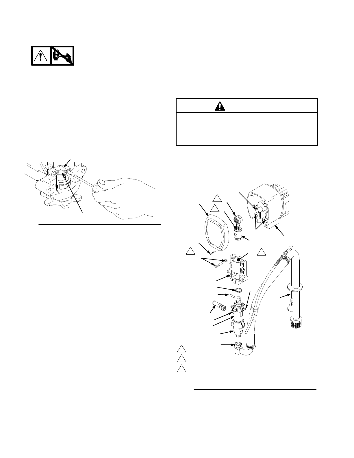
Bearing Housing and Connecting Rod
Removal
1.
Relieve pressure; page 4.
2. Fig. 2. Remove screws (27) and front cover (92).
3. Unscrew suction tube (12) from pump, hold
wrench on pump intake valve (A) to keep pump
from loosening.
4. Disconnect pump outlet hose (61) from displace-
ment pump outlet nipple (6).
5. Fig. 1. Use screwdriver to push up retaining spring
(95) at top of pump. Push out pin (96).
96
Fig. 1
95
7675B
6. Fig. 2. Loosen retaining nut (97). Unscrew and
remove displacement pump (119).
7. Remove four screws (26) and lockwashers (25)
from bearing housing (94).
3. Clean mating surfaces of bearing and drive housings.
4. Align connecting rod with crank (B) and carefully
align locating pins (F) in drive housing (101) with
holes in bearing housing (94). Push bearing housing onto drive housing or tap into place with plastic
mallet.
CAUTION
DO NOT use bearing housing screws (26) to align
or seat bearing housing with drive housing. Align
these parts with locating pins (F), to avoid premature bearing wear.
5. Install screws (26) and lockwashers (25) on bearing housing. Torque evenly to not e 3 value in Fig. 2.
6. Refer to Displacement Pump, Installation, page 15.
B
2
92
27
3
25, 26
E
D
2
F
101
83
1
C
8. Pull connecting rod (83) and lightly tap lower rear
of bearing housing (94) with plastic mallet to
loosen from drive housing (101). Pull bearing
housing and connecting rod assembly (83) off
drive housing.
9. Inspect crank (B) for excessive wear and replace
parts as needed.
Installation
1. Evenly lubricate inside of bronze bearing (C) in
bearing housing (94) with high-quality motor oil.
Liberally pack top roller bearing (E), lower bearing
(D) inside connecting rod assembly (83) with
bearing grease.
2. Assemble connecting rod (83) and bearing housing
(94).
3094148
94
95
97
96
12g
61
6
119
A
1
Oil
2
Pack with bearing grease 1 14819
3
LineLazer III 3900: Torque to 200 in-lb (22.6 N¡m)
12
ti1965a
LineLazer III 5900: Torque to 25 ft-lb (34 N¡m)
Fig. 2
Model 233701 shown
Page 9
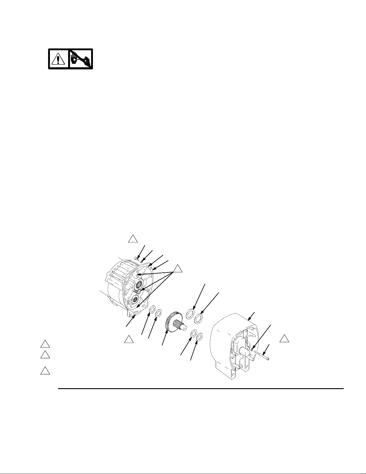
Drive Housing
Removal
1.
Relieve pressure; page 4.
2. Fig. 3. Remove bearing housing. Do 1. through 8.
of Bearing Housing and Connecting Rod procedure on page 8.
3. Fig. 3. Disconnect gallon counter sensor at (A).
Cut tie wrap holding gallon counting sensor
wire to clutch wire.
4. Fig. 3. Remove two screws (145) and lockwashers
(122).
5. Remove four screws (102) and lockwashers (122)
from pinion housing (183).
6. Lightly tap around drive housing (101) to loosen
drive housing. Pull drive housing straight off pinion
housing. Be prepared to support gear cluster (99),
which may also come out.
Installation
1. Liberally apply bearing grease (supplied with
replacement gear cluster) to gear cluster (99) and
to areas called out by note 3. Use full 0.62 pint
(0.29 liter) of grease for LineLazer III 3900 and
0.68 pint (0.32 liter) of grease for LineLazer III
5900.
2. Place bronze colored washer (101g) on shaft
protruding from large shaft of drive housing (101).
Place silver colored washer (101h) on pinion
housing. Align gears and push new drive housing
straight onto pinion housing and locating pins (B).
3. Install four screws (102) and lockwashers (122)
from pinion housing (183).
4. Install two screws (145) and lockwashers (122).
5. Fig. 2. Connect gallon counter sensor at (A).
Secure gallon counting sensor wire to clutch
wire with a tie wrap.
6. Fig. 3. Install bearing housing. Do 1. through 6. of
Bearing Housing and Connecting Rod procedure on page 8.
B
1
LineLazer III 3900 only
2
Torque to 125 in-lb -- LineLazer III 3900
Torque to 200 in-lb -- LineLazer III 5900
3
Apply remaining grease to these areas
Fig. 3
2
102
122
B
183
3
101h
101g
101
250
2
98
1
98
145
99
100
98
TI0178A
309414 9
Page 10
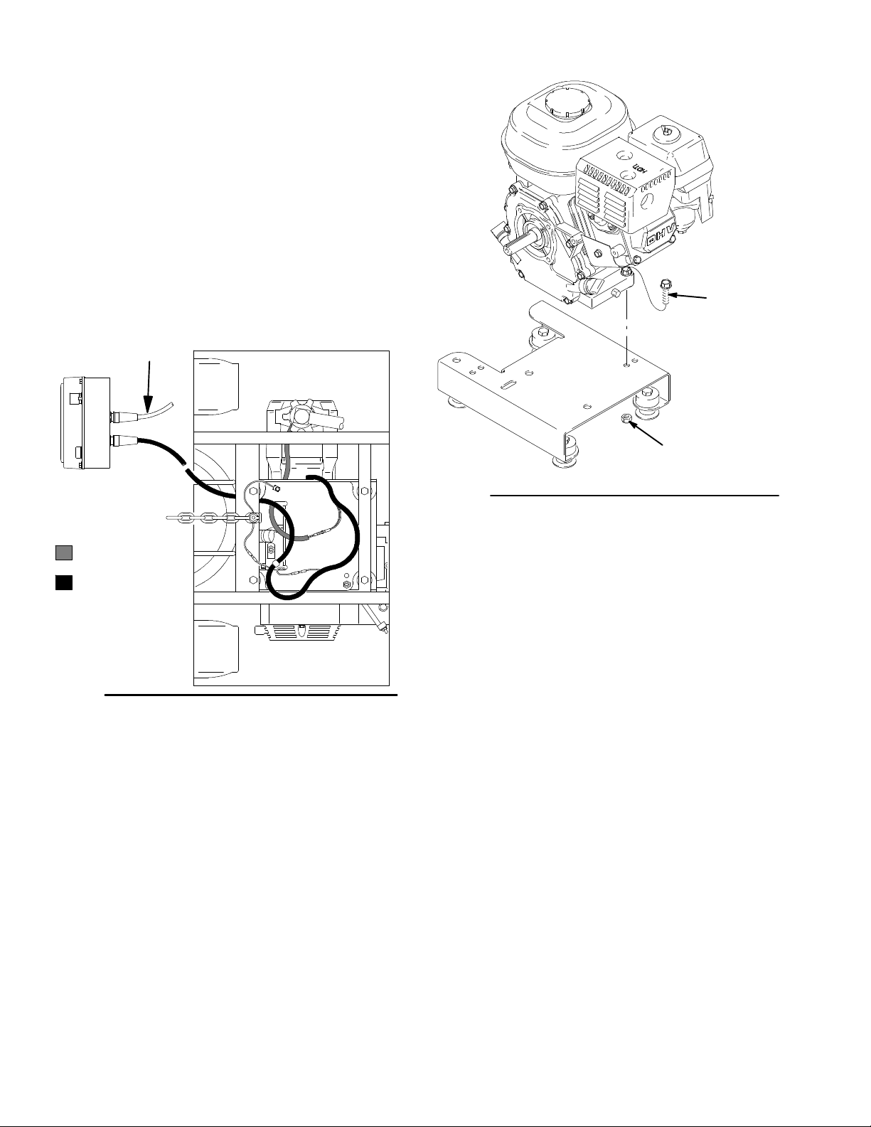
Engine
Removal
1. Remove Pinion Assembly/Rotor/Field/Pinion/
Clutch, Clamp and Clutch Housing,asin-
structed in Manual 309890.
2. Fig. 4. Disconnect all necessary wiring.
3. Fig. 5. Remove two locknuts (72) and screws
(131) from base of engine.
4. Lift engine carefully and place on work bench.
NOTE: All service to the engine must be performed by
an authorized HONDA dealer.
to Trigger/Distance sensor
Pressure Control
Gallon Counter Cable
Clutch Field Cable
ti1956a
Fig. 4
Bottom View
131
72
Fig. 5
Installation
1. Lift engine carefully and place on cart.
2. Fig. 5. Install two screws (131) in base of engine
and secure with locknuts (72). Torque to 200 in-lb
(22.6 NSm).
3. Fig. 4. Connect all necessary wiring.
4. Install Pinion Assembly/Rotor/Field/Pinion/
Clutch, Clamp and Clutch Housing,as
instructed in Manual 309890.
8827A
30941410
Page 11

On/Off Switch
Removal
1.
2. Fig. 6. Remove four screws (93) and
display/cover (139).
3. Pull display connector wings (A) open on PC board
and pull display connector out.
4. Disconnect ON/OFF switch connector (B) from PC
board.
5. Press in on two retaining tabs on each side of
ON/OFF switch (24) and remove switch.
169
Relieve pressure; page 4.
139
93
214
Installation
1. Install new ON/OFF switch (24) so tabs of switch
snap into place on inside of pressure control
housing.
2. Connect ON/OFF switch connector (B) to PC
board.
3. Push display connector into PC board close display connector wings (A) on PC board.
4. Install display/cover (139) with four screws (93).
F
108
Z
Y
Fig. 6
214
109
A
24
B
Back View (42)
E
D
ti1945a
309414 11
Page 12

Trigger Sensor Adjustment
Refer to Troubleshooting for trigger sensor adjustment, and Manual 309413.
Distance Sensor Adjustment
Gear Alignment
1.
2. Fig. 7. Remove dust cap (74) from wheel.
Remove nut (62).
3. Remove wheel (82) from LineLazer.
4. Align gear (57) with sensor.
a. Pull gear out from wheel with gear puller.
b. Push gear in toward wheel with mallet.
Relieve pressure; page 4.
5. Install wheel (82) on LineLazer.
6. Install nut (62) until tight, then back off 1/4 turn.
Install dust cap (74) on wheel.
Sensor Height Adjustment
1. Remove wheel (82) from LineLazer.
2. Remove sensor assembly (58).
3. Adjust sensor assembly height with two 17 mm
nuts of sensor so bottom surface of sensor is
0.638 +/--0.020 from bottom surface of shield.
Torque to 8 +/-- 2 in-lb.
Fig. 7
Distance
Sensor
Frame
.638 in.
Tire
Inside of tire
Axle
Gear
ti1955a
30941412
Page 13

Pressure Control
Control Board
Removal
1.
2. Fig. 6. Remove four screws (93) and
display/cover (139). Pull display connector wings
open on PC board and pull display connector out.
3. Fig. 14. Disconnect at control board (109):
D Lead (D) from potentiometer.
D Lead (E) from transducer.
D Remove ON/OFF switch (24) connector (A).
4. Fig. 6. Remove six screws (214) from control board
(109) and green ground wire.
5. Remove two connectors (Y) at backside of pressure control. Remove jam nuts (Z) and control
board (109).
Relieve pressure; page 4.
Pressure Control Transducer
Removal
1.
2. Fig. 6. Remove four screws (93) and
display/cover (139).
3. Disconnect lead (E) from control board (109).
4. Remove two screws (201) that connect control
housing (108) to filter housing (200e). From inside
of control box, pull transducer connector through
control housing (108).
Relieve pressure; page 4.
Installation
When installing replacement control board, follow
instructions with control board to set model type.
1. Fig. 6. Install control board (109) and jam nuts (Z).
Install two connectors (Y) at backside of pressure
control.
2. Install green ground wire and control board (109)
with six screws (214).
3. Fig. 14. Connect to control board (109):
D Connect ON/OFF switch (24) connector (A).
D Lead (E) to transducer.
D Lead (D) to potentiometer.
4. Fig. 6. Push display connector into PC board close
display connector wings on PC board. Install
display/cover (139) with four screws (93).
5. Remove pressure control transducer (200p) and
o-ring (200r) from filter housing (200e).
Installation
1. Fig. 6. Install o-ring (200r) and pressure control
transducer (200p) in filter housing (200e). Torque
to 30--36 ft-lb.
2. Install transducer cable through control box. Install
filter housing and spacer to control box with two
screws (201).
3. Connect lead (E) to motor control board (109).
4. Install display/cover (139) with four screws (93).
Pressure Adjust Potentiometer
Removal
1.
2. Fig. 6. Remove four screws (93) and
display/cover (139).
3. Disconnect lead (D) from control board (109).
4. Loosen set screws on potentiometer knob (19) and
remove knob, shaft nut, lockwasher and pressure
adjust potentiometer (81).
5. Remove seal (148) from potentiometer (81).
Relieve pressure; page 4.
Installation
1. Install seal (148) on potentiometer (81).
2. Fig. 6. Install pressure adjust potentiometer (81),
shaft nut, lockwasher and potentiometer knob (19).
a. Turn potentiometer shaft (81) clockwise to
internal stop. Assemble potentiometer knob
(19) to strike pin on plate (23).
b. After adjustment of step a., tighten both set
screws in knob 1/4 to 3/8 turn after contact
with shaft.
3. Connect lead (D) to control board (109).
4. Install display/cover (139) with four screws (93).
309414 13
Page 14

Control Board Diagnostics
Digital Display Messages
Relieve pressure before repair; page 4. No display does not mean that sprayer is not pressurized.
DISPLAY SPRAYER
OPERATION
No Display Sprayer may be pressurized. Loss of power or display
not connected
Sprayer may be pressurized. Pressure less than
200 psi (14 bar, 1.4 MPa)
psi
bar
MPa
Sprayer is pressurized. Power is applied. (Pressure varies with tip size and
pressure control setting.)
Sprayer stops. Engine is running. Exceeded pressure limit Remove any filter clogs or
Sprayer stops. Engine is running. Pressure transducer faulty,
Sprayer stops. Engine is running. High clutch current 1. Check clutch 7--pin bulk-
Normal operation Spray
bad connection or broken
wire.
INDICATION ACTION
Check power source. Relieve
pressure before repair or disassembly. Verify display is
connected.
Increase pressure as needed
flow obstructions. Make sure
gun trigger is locked open if
using AutoClean valve.
Check transducer connections
and wire. Replace transducer
or control board, if necessary.
head connector. Clean
contacts.
2. Measure 1.2 ±0.2Ω (LineLazer III 3900); 1.7 ±0.2Ω
(LineLazer III 5900)
across clutch f ield at 70_F
3. Replace clutch field assembly
Sprayer stops. Engine is running.
Display alternates E=06.
High clutch temperature 1. If clutch is new, let spray-
After a fault, follow these steps t o restart sprayer:
1. Correct fault condition
2. Turn sprayer OFF
3. Turn sprayer ON
30941414
er cool down and then restart
2. Inspect clutch. Replace
clutch if there is excessive
wear.
3. Remove pump pin, separate pinion housing from
clutch housing. Rotate
rotor clockwise to check
for excessive drag.
Page 15
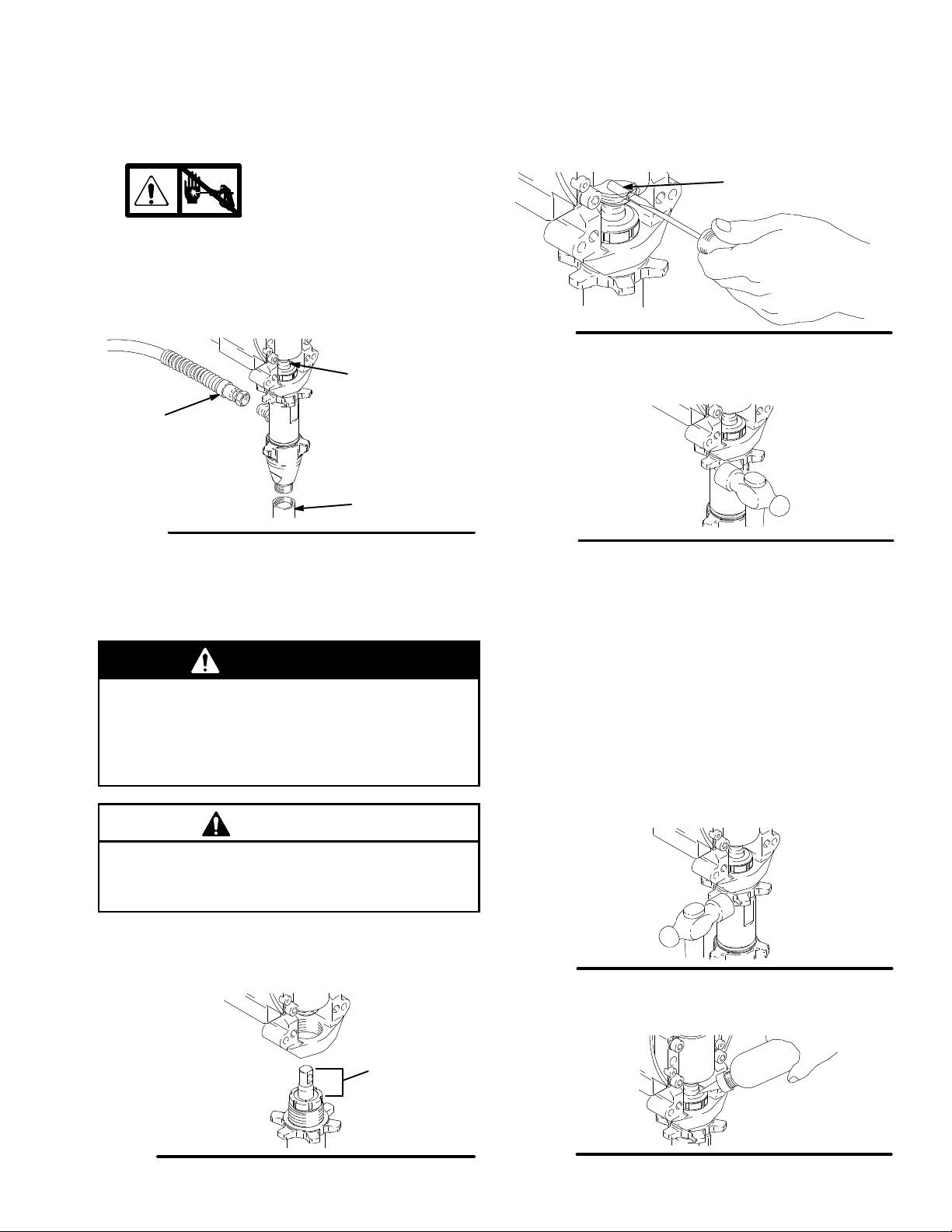
Removal
Displacement Pump
1. Flush pump.
2.
3. Fig. 8. Cycle pump with piston rod (222) in its
lowest position.
4. Fig. 8. Remove suction tube (12) and hose (61).
61
Fig. 8
Relieve pressure; page 4.
222
12
7672C
Repair
See manual 309277 for pump repair instructions.
5. Fig. 9. Use screwdriver: push retaining spring up
and push out pin (96).
96
Fig. 9
6. Fig. 10. Loosen locknut by hitting firmly with a
20 oz (maximum) hammer. Unscrew pump.
Fig. 10
7673B
7675B
Installation
WARNING
If pin works loose, parts could break off due to
force of pumping action. Parts could project
through the air and result in serious injury or property damage. Make sure pin and retaining spring
are properly installed.
CAUTION
If the pump locknut loosens during operation, the
threads of the bearing housing will be damaged.
Make sure locknut is properly tightened.
1. Fig. 11. Pull piston rod out 1.5 in. Screw in pump
until holes in bearing cross link and piston rod
align.
2. Fig. 9. Push pin (96) into hole. And push retaining
spring into groove all the way around connecting
rod.
Fig. 12. Screw jam nut down onto pump until nut
stops. Screw pump up into bearing housing until it is
stopped by jam nut. Back off pump and jam nut to
align pump outlet to back. Tighten jam nut by hand,
thentap1/8to1/4turnwitha20oz(maximum)ham-
mer to approximately 75 5ft--lb(102N¡m).
Fig. 12
Fig. 13. Fill packing nut with Graco TSL until fluid flows
onto the top of seal.
7673B
Fig. 11
1.5 in.
7676B
Fig. 13
7677B
309414 15
Page 16

Parts -- Pinion and Drive Housing Assemblies
Ref No. 183 and 101
Ref No. 183: Pinion Housing Assembly 245715 for
LineLazer III 3900; Pinion Housing Assembly
245834 for LineLazer 5900
Ref
No. Part No. Description Qty
183 PINION HOUSING 1
183a KIT, repair, coil
245419 LineLazer III 3900 1
245420 LineLazer III 5900 1
183b 105489 PIN 2
183d* PINION SHAFT
241110 LineLazer III 3900 1
241114 LineLazer III 5900 1
183e* RETAINING RING, large
113094 LineLazer III 3900 1
112770 LineLazer III 5900 1
*Must be ordered separately.
183e
183d
183b
102 (Ref)
122 (Ref)
Ref No. 101: Drive Housing Assembly 245442 for
LineLazer III 3900; Drive Housing Assembly 245443
for LineLazer III 5900
Ref
No. Part No. Description Qty
101 DRIVE HOUSING 1
101g WASHER
107089 LineLazer III 3900 1
194173 LineLazer III 5900 1
101h WASHER
116191 LineLazer III 3900 1
116192 LineLazer III 5900 1
28 116806 SWITCH, reed 1
173 116838 PIN, spring 2
147 116618 MAGNET 1
183a
101h
101g
98 (Ref)
98 (Ref)
2
1
99 (Ref)
100 (Ref)
1
Only used on LineLazer III 3900, Models 233688 and 233664
2
Pinion housing assembly (183) includes clutch field and connector
101
250 (Ref)
147
145 (Ref)
173
28
TI0177B
30941416
Page 17

Parts Page 26
Parts Page 24
Parts -- LineLazer III
Parts Page 20
Parts Page 18
Parts Page 22
Parts Page 24
Sheet 1 of 6
ti1954a
309414 17
Page 18

Parts -- LineLazer III
Models 233688 and 233690
46
51
6
13
7
42
161
166
70
134
162
222
52
80
140
172
202
9
74
62
82
15
162
188
64
58
54
57
72
75
72
70
137
69
130
68
129
67
68
177
131
194
18
66
167
Sheet 2 of 6
ti1938a
30941418
Page 19

Parts -- LineLazer III
Ref.
No. Part No. Description Qty.
6 196176 ADAPTER, nipple 2
7 114271 STRAP, retaining 1
9 114808 CAP, vinyl 1
13 245798 HOSE, 1/4 in. X 7 ft 2
15 178342 CLIP, spring 6
18 186620 LABEL, symbol, ground 1
42 245224 HANDLE, linelazer 1
46 114659 GRIP, handle 2
51 245225 HOSE, 3/8 in. X 50 ft 1
52 241005 COVER, pail 1
54 198612 BRACKET, sensor, distance 1
57 245734 KIT, repair, wheel, LineLazer 1
includes 82
58 245597 SENSOR, distance,
includes 54, 64,162, 188 1
62 112405 NUT, lock 3
64 108868 CLAMP, wire 3
66 240999 CONDUCTOR, ground 1
67 114653 SCREW, cap, flange hd 1
68 100731 WASHER 4
69 186812 CHAIN, ground 3.5 hp 1
70 111194 SCREW, cap flang hd 6
Ref.
No. Part No. Description Qty.
72 101566 NUT, lock 12
74 114648 CAP, dust 2
75 186821 LABEL, warning 2
80 114690 STRAP 2
82 111020 WHEEL, pneumatic 1
129 110838 NUT, lock 5
130 111040 NUT, lock, insert, nylock, 5/16 5
131 110837 SCREW, flange, hex 7
134 237686 CLAMP, grounding assy 1
137 193405 AXLE 1
140 115077 PAIL, plastic 1
161 194310 LEVER, actuator 1
162 112798 SCREW, thread forming, hex hd 2
166 241445 CABLE 1
167 245246 FRAME, linestriper 1
172 198931 BEARING 1
177 198930 ROD, brake 1
188 116287 WASHER, sst, external, starwasher 1
194 198891 BRACKET, mounting, 1
202 195134 SPACER, ball, guide 1
222 113961 SCREW, cap, hex hd 1
309414 19
Page 20

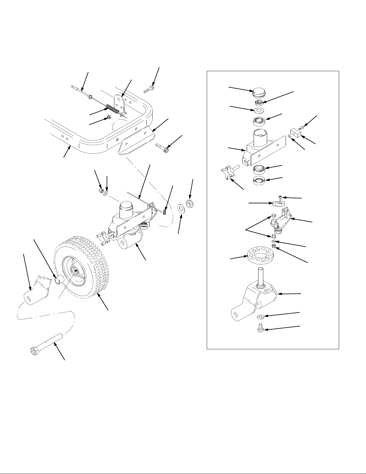
Parts -- LineLazer III
2
6
2
3
7
Models 233688 and 233690
101
117
28
143
145
94
97
141
27
92
26
173
83
25
95
96
61
6
119
183
99
100
250
12 (see Detail E)
122
147
98
102
150
132
86
122
87
122
84
85
65
89
88
129
9190
146
102
122
132
66
7
12
12g
12m
12n
12a
12d
12h
12b
12k
12j
30941420
12d
12c
Detail E (12)
12e
12f
Sheet 3 of 6
38
40
126
65
64
1
130
24
ti1942a
Page 21

Parts -- LineLazer III
Ref.
No. Part No. Description Qty.
6 196176 ADAPTER, nipple 2
12 245730 HOSE, suction and drain
(includes 12a--12n) 1
12a 170957 TUBE, suction 1
12b 185381 HOSE 1
12c 110194 SWIVEL, 180_ 1
12d 101818 CLAMP, hose 1
12e 193711 GASKET, pail 1
12f 181072 STRAINER 1
12g 245731 TUBE, drain (includes diffuser) 1
12h DIFFUSER 1
12j 245798 HOSE, coupled, 1/4 in. x 7 ft 1
12k 114958 STRAP, tie 2
12m 196180 BUSHING 1
12nY 195119 LABEL, warning 1
25 106115 WASHER, lock spring (hi-collar) 4
26 SCREW, cap, socket hd
107210 (3900) 4
114666 (5900) 4
27 SCREW, self tap, fil hd 4
114418 (3900) 4
114818 (5900) 4
28 116806 SWITCH, reed 1
37 106212 SCREW, cap, hex hd 4
38 193677 PLATE, mounting 1
40 113802 SCREW, hex hd, flanged 1
61 245797 HOSE, 3/8 in. X 3 ft 1
63 195515 DAMPENER, motor mount 4
64 108868 CLAMP, wire 3
65 110963 SCREW, cap, flng hd 2
66 240999 CONDUCTOR, ground 1
72 101566 NUT, lock 12
83 ROD, connecting
241008 (3900) 1
241012 (5900) 1
84 WASHER, lock, spring
104008 (3900) 4
100214 (5900) 4
85 SCREW, cap, sch
109031 (3900) 4
108842 (5900) 4
86 183401 KEY, parallel 1
87 193680 COLLAR, shaft 1
88 HUB, armature (see 229) 1
89 HOUSING, clutch
193540 (3900) 1
193531 (5900) 1
90 ROTOR, clutch (see 229) 1
91 101682 SCREW, cap, sch 4
92 COVER, housing
179899 (3900) 1
241308 (5900) 1
94 240523 HOUSING, bearing (3900) 1
241015 HOUSING, bearing (5900) 1
95 SPRING, retaining
Ref.
No. Part No. Description Qty.
176817 (3900) 1
183169 (5900) 1
96 PIN, str, hdls
176818 (3900) 1
183210 (5900) 1
97 192723 NUT, retaining (3900) 1
193031 NUT, retaining (5900) 1
98 WASHER, thrust
114672 WASHER, thrust (3900) 3
114672 WASHER, thrust (5900) 2
99 241439 GEAR, combination (3900) 1
241440 GEAR, combination (5900) 1
100 114699 WASHER, thrust 1
101 HOUSING, drive, includes 28, 147, 173
245442 (3900) 1
245443 (5900) 1
(includes 28, 117, 143, 147, 173)
102 100644 SCREW, cap, sch 9
117Y 290228 LABEL, caution 1
119 PUMP, displacement
244197 (3900) 1
244224 (5900) 1
Manual 309277
120 195516 SPACER 4
122 105510 WASHER, lock, spring (hi--collar) 19
127 108851 WASHER, plain 4
129 110838 NUT, lock 5
130 111040 NUT, lock, insert, nylock, 5/16 5
132 108803 SCREW, hex, socket head 6
141 LABEL, front
198605 (3900) 1
198883 (5900) 1
143Y 194125 LABEL, danger, English 1
145 SCREW, cap, soc. hd
107218 (3900) 2
114686 (5900) 2
250 WASHER
105510 (3900) 2
104008 (5900) 2
146 ENGINE, gasoline
108879 (3900) 1
114530 (5900) 1
147 116618 MAGNET 1
150 ARMATURE, clutch, 4 in.(see 229) 1
173 116838 PIN, spring 2
183 HOUSING, pinion
245715 (3900) 1
245834 (5900) 1
229 KIT, clutch
241109 (3900) 1
241113 (5900) 1
includes 88, 90, 91, 122, 132, 150
Y Replacement Danger and Warning labels, tags, and cards
are available at no cost.
309414 21
Page 22
Models 233688 and 233690
Parts -- LineLazer III
144
Ref. 164
Ref. 167
Ref. 166
41
130
72
68
76
Ref. 166
164 (see Detail D)
131
152
158
157
116
62
164n
164k
164a
164u
164d
164g
164f
164j
164j
164h
164m
164w
164v
164x
164e
164c
164p
164r
164b
F
156
Detail D (164)
154
164s
164t
ti1940a
Sheet 4 of 6
30941422
Page 23

Parts -- LineLazer III
Ref.
No. Part No. Description Qty.
41 114682 SPRING, compression 1
62 112405 NUT, lock 3
68 100731 WASHER 4
72 101566 NUT, lock 12
76 193665 BRACKET, cable 1
116 114982 SCREW, cap, flng hd 2
131 110837 SCREW, flange, hex 7
144 193658 SPACER, seal 2
152 240991 BRACKET, caster, front 1
154 113471 SCREW, cap, hex hd 1
156 114549 WHEEL, pneumatic 1
157 112825 SPRING, belleville 1
158 114802 STOP, wire 1
164 241105 CASTER, swivel 1
164a 240940 KIT, repair, bracket, hub 1
includes 164j (2), 164h
164b 240942 SHAFT, fork 1
164c 193528 ARM, detent 1
Ref.
No. Part No. Description Qty.
164d 193662 PIN, locking, tapered 1
164e 110754 SCREW, cap, soc hd 1
164f 181818 KNOB, pronged 1
164g 114548 BEARING, bronze 1
164h 113484 SEAL, grease 1
164j 113485 BEARING, cup/cone 2
164k 112825 SPRING, Belleville 1
164m 112405 NUT, lock 1
164n 114648 CAP, dust 1
164p 107194 WASHER, plain 1
164r 108000 NUT, lock 1
164s 113962 WASHER, hardened 1
164t 114681 SCREW, cap, hex hd 1
164u 198606 DISK, adjuster 1
164v 193661 JAW 1
164w 108483 SCREW, shoulder, soc hd 1
164x 112776 WASHER, plain 1
309414 23
Page 24

Ref. 182
79
Parts -- LineLazer III
Models 233688 and 233690
17
5
78
16
Ref. 13
115,118
39
Ref. 167
11
2
32
77
3
30c
133
182
124
30 (See Detail B)
4
113
30a
30d
30e
30m
Detail B (30)
30n
30k
30f
30g
30j
30p
30n
30b
30h
Ref. 46
191
205
204
215
35
30941424
181
190
Ref. 204
178
212
181
35
Ref. 182
213
180
182
ti1939a
Ref. 42
To Display Sensor
207
Sheet 5 of 6
Page 25

Parts -- LineLazer III
Ref.
No. Part No. Description Qty.
2 100021 SCREW, cap hex hd 2
3 100016 WASHER, lock 2
4 243284 GUN, flex, basic 1
Manual 309093
5 240780 BRACKET, arm, gun 2
11 100101 SCREW, cap, hex hd 1
16 224052 BRACKET, support gun 1
17 108471 KNOB, pronged 2
30 241001 HOLDER, gun 1
30a 188452 HOLDER, gun 1
30b 186747 LEVER, actuator 1
30c 181818 KNOB, pronged 1
30d 181795 JAW, clamped 1
30e 108483 SCREW, shoulder, sch 1
30f 100846 FITTING, lubrication 1
30g 107445 SCREW, cap 1
30h 108535 BEARING, sleeve 1
30j 101345 NUT, hex, jam 1
30k 110755 WASHER, plain 1
30m 100015 NUT, hex MSCR 1
30n 111016 BEARING, flange 2
30p 111045 SCREW, shoulder 1
32 100133 WASHER, lock 1
Ref.
No. Part No. Description Qty.
35 111017 BEARING, flange 2
39 186699 BLOCK, mounting, cable 1
77 181734 ARM, support 1
78 114029 CLAMP, swivel, adjustable 1
79 188135 GUIDE, cable 1
113 243161 GUARD, RAC 5 1
115 286517 TIP, spray, RAC--5 1
118 LL5319 TIP, spray, RAC 5, striping 1
124 101345 NUT, hex, jam 1
133 111230 SCREW, mach, flhd 1
178 198896 BLOCK, mounting (mach) 1
180 116941 SCREW, shoulder, socket head 1
181 198895 PLATE, lever, pivot 2
182 245732 KIT, cable 1
190 116973 SCREW, #10 taptite phil 1
191 116969 NUT, lock 1
204 245733 TRIGGER, 1
includes 205, 212, 213, 215
205 15A644 LABEL, trigger 1
207 245713 BRACKET, sensor and magnet 1
212 117269 SPRING 1
213 117268 BRACKET, interrupter 1
215 112381 SCREW, mach, pan hd 1
309414 25
Page 26

Parts -- LineLazer III
93
189
195
149
225
174
139
1
169
8
24
220
19
114
23
214
169
184
148
81
109
108
198
186
201
200 (See Detail A)
199
176
49
Ref.12j
Back View (42)
Models 233688 and 233690
48
47
48
61
Ref. 51
185
200a
200b
216
200c
10
20
196
Ref. 42
Ref. 58
Ref. 183
200n
Detail A (200)
200p
ti1941a
200k
200m
200j
200d
200r
200e
200f
200g
200h
30941426
Page 27

Parts -- LineLazer III
Ref.
No. Part No. Description Qty.
1 114955 CONTROL, throttle 1
8 114954 SWITCH, rocker 1
10 109466 NUT, lock, hex 2
19 116167 KNOB, potentiometer 1
20 112380 SCREW, mach, pan hd 2
23 198553 PANEL, control 1
24 116752 SWITCH, rocker 1
47 196179 FITTING, elbow, street 1
48 196178 ADAPTER, nipple 2
49 196177 ADAPTER, nipple 1
61 245797 HOSE, 3/8 in. X 3 ft 1
81 241443 POTENTIOMETER 1
93 116252 SCREW, #8 taptite phil 4
108 198602 BOX, control 1
109 245512 BOARD, control, linelazer 1
114 196670 LABEL, crtl box cover 1
139 245791 KIT, display, 1
includes 93, 114, 149, 174
148 198650 SPACER, shaft 1
149 198648 LABEL, LCD 1
169 114393 SCREW, mach, pan hd 4
174 198649 LABEL, LCD instructional 1
176 196181 FITTING, nipple 1
184 116876 WASHER, flat 2
185 245441 PLUG, packless 1
186 198999 LABEL, instruction 1
189 100035 SCREW, mach, pnh 3
195 198942 PLATE, side 1
Ref.
No. Part No. Description Qty.
196Y 15A245 LABEL, warning 1
198Y 189246 LABEL, warning 1
199 198684 SPACER, base 1
200 245515 FILTER, assembly 1
200a 196675 BOWL, FILTER 1
200b 104361 O-RING 1
200c 244067 FILTER, fluid 1
200d 196786 TUBE, diffuser 1
200e 245796 HOUSING, filter, 3/8 npt 1
200f 193710 SEAL, valve 1
200g 193709 SEAT, valve 1
200h 114797 GASKET 1
200j 245103* VALVE 1
200k 114708 SPRING, compression 1
200m 194102 HANDLE, valve 1
200n 114688 NUT, cap, hex hd 1
200p 243222 TRANSDUCER 1
includes 200p
200r 111457 SEAL 1
201 117232 SCREW, cap, hex hd 3
214 114331 SCREW, mach, pnh, sems 6
216 15A621 LABEL, identification 1
220 198975 WIRE, ground 1
225 15A670 CONDUCTOR, electrical 1
* Drain valve replacement kit 245103 includes 200f, g, h, k,
m, n
Y Replacement Danger and Warning labels, tags, and cards
are available at no cost.
309414 27
Page 28

Pressure Control Wiring Diagram
Display Board
125
Drive
Housing
101
To Engine
146
Pinion
Housing
183
Control Board
109
Clutch Test Points
View A View B
ON/OFF Switch
24
Transducer
200p
Potentiometer
81
Fig. 14
View A
Engine
Power
Gallon
Counting
Sensor
Trigger Sensor
Clutch
Coil
Thermistor
View B
Distance Sensor
ti1943a
30941428
Page 29

Accessories
DANGER LABELS
An English language DANGER label is on your
sprayer. If you have painters who do not read English, order one of the following labels to apply to
your sprayer. The drawing shows the best placement of these labels for good visibility.
Order the labels from your Graco distributor.
French 194931
Spanish 194932
German 194933
Greek 194934
Korean 194935
English 194125
Apply other
language here
Technical Data
03497A
Honda GX120 Engine
Power Rating @ 3600 rpm
ANSI 4.0 Horsepower.......................
DIN 6270B/DIN 6271
NA 2.1 Kw -- 2.8 Ps......................
NB 2.6 Kw -- 3.6 Ps......................
Honda GX160 Engine
Power Rating @ 3600 rpm
ANSI 5.5 Horsepower.......................
DIN 6270B/DIN 6271
NA 2.9 Kw -- 4.0 Ps......................
NB 3.6 Kw -- 4.9 Ps......................
Maximum working pressure 3300 psi...............
(228 bar, 22.8 MPa)
Noise Level
Sound power 105 dBa.........................
per ISO 3744
Sound pressure 96 dBa........................
measured at 3.1 feet (1 m)
Maximum delivery
LineLazer III 3900 1.15 gpm (4.4 liter/min).......
LineLazer III 5900 1.5 gpm (5.7 liter/min).........
Maximum tip size
LineLazer III 3900 1 gun with 0. 034 in. tip.......
LineLazer III 5900 1 gun with 0. 041 in. tip.......
Inlet paint strainer 16 mesh (1190 micron)...........
Outlet paint filter 60 mesh (250 micron).............
Pump inlet size 3/4 in. npt (m)......................
Fluid outlet size 1/4 npsm from fluid filter............
Wetted parts nickel--plated carbon steel,............
PTFE, Nylon, polyurethane, UHMW polyethylene,
Viton
r,Delrinr, leather, tungsten carbide, stainless
steel, chrome plating
NOTE: Delrinr and Vitonr are trademarks of the DuPont
Company.
Dimensions
LineLazer III 3900
2 guns with 0.024 in. tip
2 guns with 0.028 in. tip
stainless steel screen, reusable
stainless steel screen, reusable
Model 233688, 233664 Striper
Weight (dry, without packaging) 212 lb (96 kg).......
Height 40 in. (101.6 cm)..........................
Length 65 in. (165.1 cm)..........................
Width 32 in. (81.3 cm)............................
Model 233690, 233627 Striper
Weight (dry, without packaging) 232 lb (105 kg)......
Height 40 in. (101.6 cm)..........................
Length 65 in. (165.1 cm)..........................
Width 32 in. (81.3 cm)............................
Model 233689, 233694 Striper with 2nd Gun Kit
Weight (dry, without packaging) 222 lb (101 kg)......
Height 40 in. (101.6 cm)..........................
Length 65 in. (165.1 cm)..........................
Width 32 in. (81.3 cm)............................
LineLazer III 5900
Model 233691, 233695 Striper with 2nd Gun Kit
Weight (dry, without packaging) 242 lb (110 kg)......
Height 40 in. (101.6 cm)..........................
Length 65 in. (165.1 cm)..........................
Width 32 in. (81.3 cm)............................
309414 29
Page 30

Graco Standard Warranty
Graco warrants all equipment manufactured byGraco andbearing its nameto be free from defects in material andworkmanship onthe
date of sale by an authorized Gracodistributorto the original purchaser foruse. With theexception ofany special, extended, orlimited
warranty published by Graco, Graco will, for a period of twelve months from the date of sale, repair or replace any part of the equipment
determined by Graco to be defective. This warranty applies only when the equipment is installed, operated and maintained in accordance with Graco’s written recommendations.
This warranty does not cover, and Graco shall not be liable for general wear and tear, or any malfunction, damage orwear caused by
faultyinstallation, misapplication,abrasion, corrosion,inadequate or improper maintenance,negligence, accident,tampering, or substitution of non--Graco component parts. Nor shall Graco be liable for malfunction, damage or wear caused by the incompatibility of
Graco equipment with structures, accessories, equipment or materials not supplied by Graco, or the improper design, manufacture,
installation, operation or maintenance of s tructures, accessories, equipment or materials not supplied by Graco.
This warranty is conditioned upon the prepaid return of the equipment claimed to be defective to an authorized Graco distributor for
verification of the c laimed defect. If the claimed defect is verified, Graco will repair or replace free of charge any defective parts. The
equipmentwill be returnedto theoriginal purchaser transportation prepaid. Ifinspection of the equipment does not disclose any defect
in material or workmanship, repairs will be made at a reasonable charge, which charges may include the costs of parts, labor, and
transportation.
THIS WARRANTY IS EXCLUSIVE, AND IS IN LIEU OF ANY OTHER WARRANTIES, EXPRESS OR IMPLIED, INCLUDING BUT
NOT LIMITED TO WARRANTY OF MERCHANTABILITY OR WARRANTY OF FITNESS FOR A PARTICULAR PURPOSE.
Graco’ssole obligation and buyer’ssole remedyfor any breach ofwarranty shall be as set forthabove. The buyer agrees thatno other
remedy (including, but not limited to, incidental or consequentialdamages for lost profits, lost sales, injury toperson or property, orany
other incidental or consequential loss) shall be available. Any action for breach of warrantymust be brought withintwo (2) years of the
date of sale.
Graco makes no warranty, and disclaims all implied warranties of merchantability and fitness for a particular purpose in connection
with accessories, equipment, materials or components sold but not manufactured by Graco. These items sold,but not manufactured
by Graco (such as electric motors, switches, hose, etc.), are subject to the warranty, if any, of their manufacturer. Graco will provide
purchaser with reasonable assistance in making any claim for breach of these warranties.
In no event will Graco be liable for indirect, incidental, special or consequential damages resulting from Graco supplying equipment
hereunder, or the furnishing, performance, or use of any products or other goods sold hereto, whether due to a breach of contract,
breach of warranty, the negligence of Graco, or otherwise.
FOR GRACO CANADA CUST
The parties acknowledge that they have required that the present document, as well as all documents, notices and legal proceedings
entered into, given orinstituted pursuant hereto or relating directly orindirectly hereto, be drawnup in English. Les parties reconnaissent avoirconvenu que la rédaction du présente document sera en Anglais, ainsi que tous documents, avis et procédures judiciaires
exécutés, donnés ou intentés à la suite de ou en rapport, directement ou indirectement, avec les procedures concernées.
OMERS
ADDITIONAL WARRANTY COVERAGE
Graco does provide extended warranty and wear warranty for products described in the “Graco Contractor Equipment Warranty
Program”.
Graco Phone Number
TO PLACE AN ORDER, contact your Graco distributor, or call this number to identify the distributor closest to you:
1--800--690--2894 Toll Free
All written and visual data contained in this document reflects the latest product information available at the time of publication.
Graco reserves the right to make changes at any time without notice.
Original Instructions. This manual contains English. MM 309414
GRACO INC. P.O. BOX 1441 MINNEAPOLIS, MN 55440--1441
International Offices: Belgium, China, Japan, Korea
Copyright 2002, Graco Inc. is registered to ISO 9001
Graco Headquarters: Minneapolis
www.graco.com
Revised 04/2011
30941430
 Loading...