

Page 1
Instructions
ti14387
ti14386
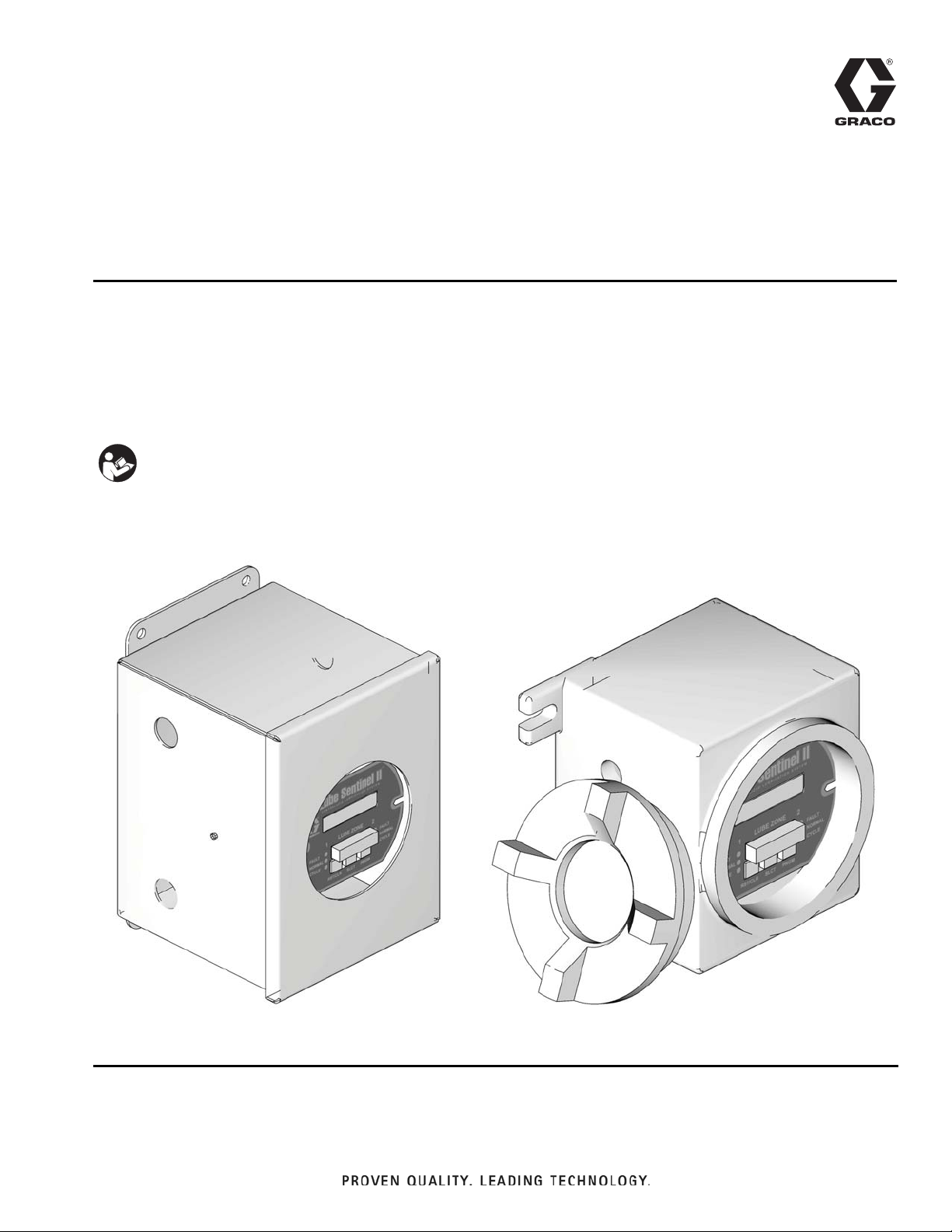
Model: 562870
Model: 562871
Lube Sentinel II
Monitor
- Monitors and computes lube cycle lubrication rates -
Part No.: 562870 JIC Enclosure - Not for use in explosive atmospheres!
Part No.: 562871 - Includes Explosion Proof Enclosure
Important Safety Instructions
Read all warnings and instructions in this manual.
Save these instructions.
See Technical Data, page 26 for model information, including power requirements.
313903C
EN
Bulletin: 44701, 555840
Page 2
Warnings
Warnings
The following warnings are for the setup, use, grounding, maintenance, and repair of this equipment. The exclamation point symbol alerts you to a general warning and the hazard symbol refers to procedure-specific risk. Refer back
to these warnings. Additional, product-specific warnings may be found throughout the body of this manual where
applicable.
WARNING
ELECTRIC SHOCK HAZARD
This equipment must be grounded. Improper grounding, setup, or usage of the system can cause electric
shock.
• Turn off and disconnect power at main switch before disconnecting any cables and before servicing
equipment.
• Connect only to grounded power source.
• All electrical wiring must be done by a qualified electrician and comply with all local codes and
regulations.
EQUIPMENT MISUSE HAZARD
Misuse can cause death or serious injury.
• Do not operate the unit when fatigued or under the influence of drugs or alcohol.
• Do not exceed the maximum working pressure or temperature rating of the lowest rated system component. See Technical Data in all equipment manuals.
• Do not leave the work area while equipment is energized or under pressure. Turn off all equipment
and follow the Pressure Relief Procedure in this manual when equipment is not in use.
• Check equipment daily. Repair or replace worn or damaged parts immediately with genuine manufacturer’s replacement parts only.
• Do not alter or modify equipment.
• Use equipment only for its intended purpose. Call your distributor for information.
• Route hoses and cables away from traffic areas, sharp edges, moving parts, and hot surfaces.
• Do not kink or over bend hoses or use hoses to pull equipment.
• Keep children and animals away from work area.
• Comply with all applicable safety regulations.
2 313903C
Page 3
Installation
AUTOMATIC SYSTEM ACTIVATION HAZARD
Unexpected activation of the system could result in serious injury, including skin injection and amputation.
This device has an automatic timer that activates the
pump lubrication system when power is connected or
when exiting the programming function. Before you
install or remove the Lube Sentinel II Monitor from the
system, disconnect and isolate all power supplies and
relieve all pressure.
Grounding
Installation
Electrical Connections
Electrical interference from improperly installed equipment may cause erratic behavior of the device.
When installing the Sentinel II, use 18 - 24 gauge
machine tool wire (MTW). 18 gauge wire is recommended for the input power.
It is also recommended that wiring be run in its own conduit to minimize electrical interference. If the installation
is in an area of high electrical noise/interference, or in
trays with other control wiring, a shielded cable pair is
recommended.
The equipment must be grounded. Grounding reduces
the risk of static and electric shock by providing an
escape wire for the electrical current due to static
build-up or in the event of a short circuit.
Ground connections should not be connected to conduits or other electrical boxes. The ground wire should
be connected to a grounding rod or a grounded bus bar
that is tied to a grounding rod in the earth.
Shielded cable should be used on applications where
engines or heavy-duty motors are in close proximity to
the monitor, wiring or sensors. If shield cable is used,
the shield should stay intact as close to the termination
screws as possible. (Do not remove shielding from cable
if it is in a shared tray).
The shield should be connected to the designated
ground at both the sensor and the monitor.
313903C 3
Page 4
Installation
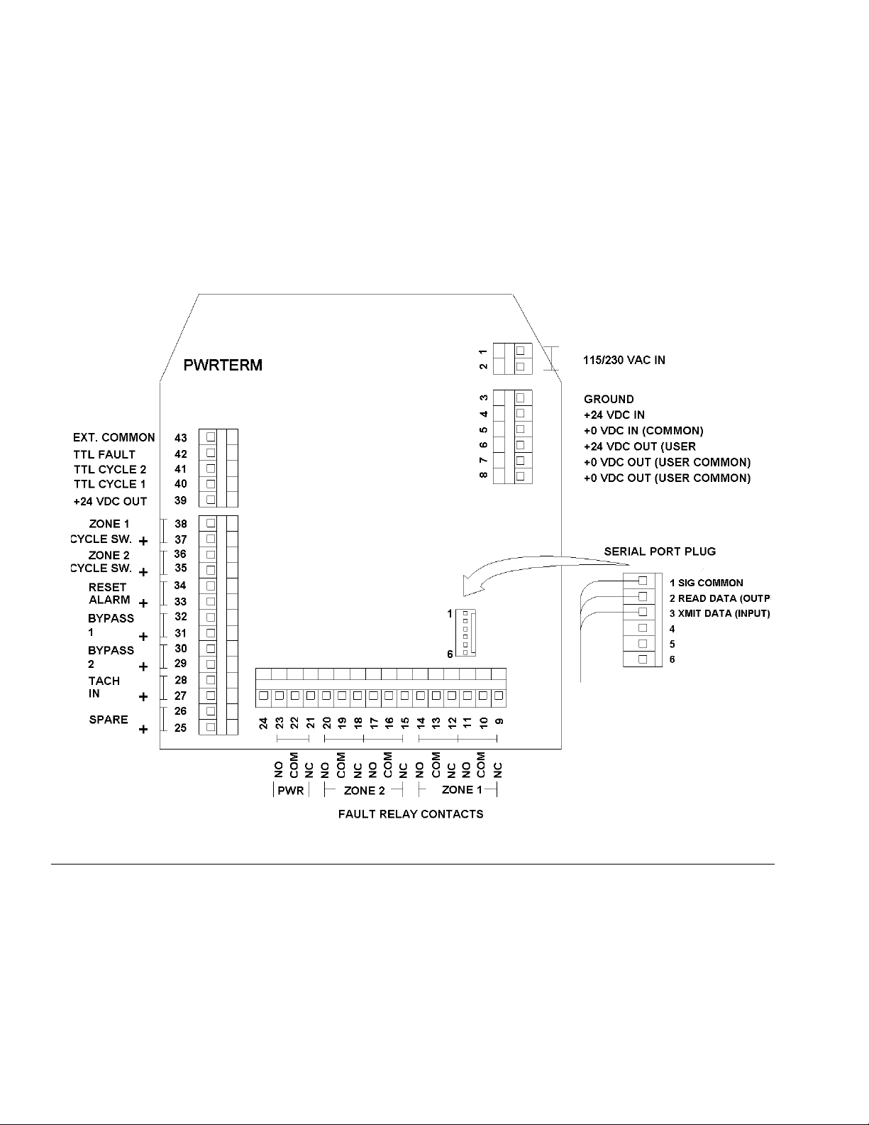
Circuit Board Connections
(FIG. 1 - FIG. 7 show the circuit board and power connections necessary to install the Lube Sentinel II Monitor in your
lubrication system.)
All electrical connections are made to terminals along both sides and the bottom of the main circuit board, except for
serial communications. Serial communication connections are made via a special plug-in header block.
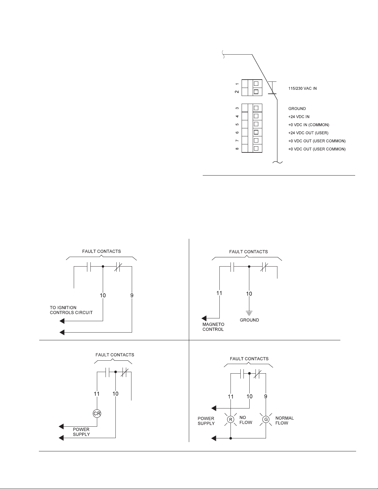
External Connection Terminals
FIG. 1
4 313903C
Page 5
Terminal Strip -
Ignition Shutdown*
Magneto Grounding
External Flow/No Flow Lights
Energize External Load (relay coil, etc.)
*NOTE: Do not
connect to high
voltage.
Connect to
controls only.
Right Side Power Connections
Terminals Power Connection
115/230 VAC power input terminals
1 & 2
(polarity insensitive)
3 Earth Ground
4 +24 VDC Input
5 0 VDC Input
6 +24 VDC Out (for sensor use)
7 0 VDC Out (for sensor use)
8 0 VDC Out (for sensor use)
F
Terminal Strip Bottom - Fault Relay Connections
Terminals 9 - 14, Zone 1 Fault Relay:
Installation
IG. 2
The zone fault relay is a double-pole, double-throw (DPDT), Form-C relay. Relay contacts are wired directly to the terminal strip. Pole “A” uses terminals 9 (N.C.), 10 (com) and 11 (N.O.). Pole “B” uses terminal 12 (N.C.), 13 (com) and
14 (N.O.). Power is not supplied to these contacts. Contacts are rated 0.5 ampere at 125VAC and 1.0 ampere at
30VDC. The relays may be programmed to either energize or deenergize during a fault. (See F
IG. 3.)
FIG. 3: Examples of Wiring for Zone 1 Faults
313903C 5
Page 6
Installation
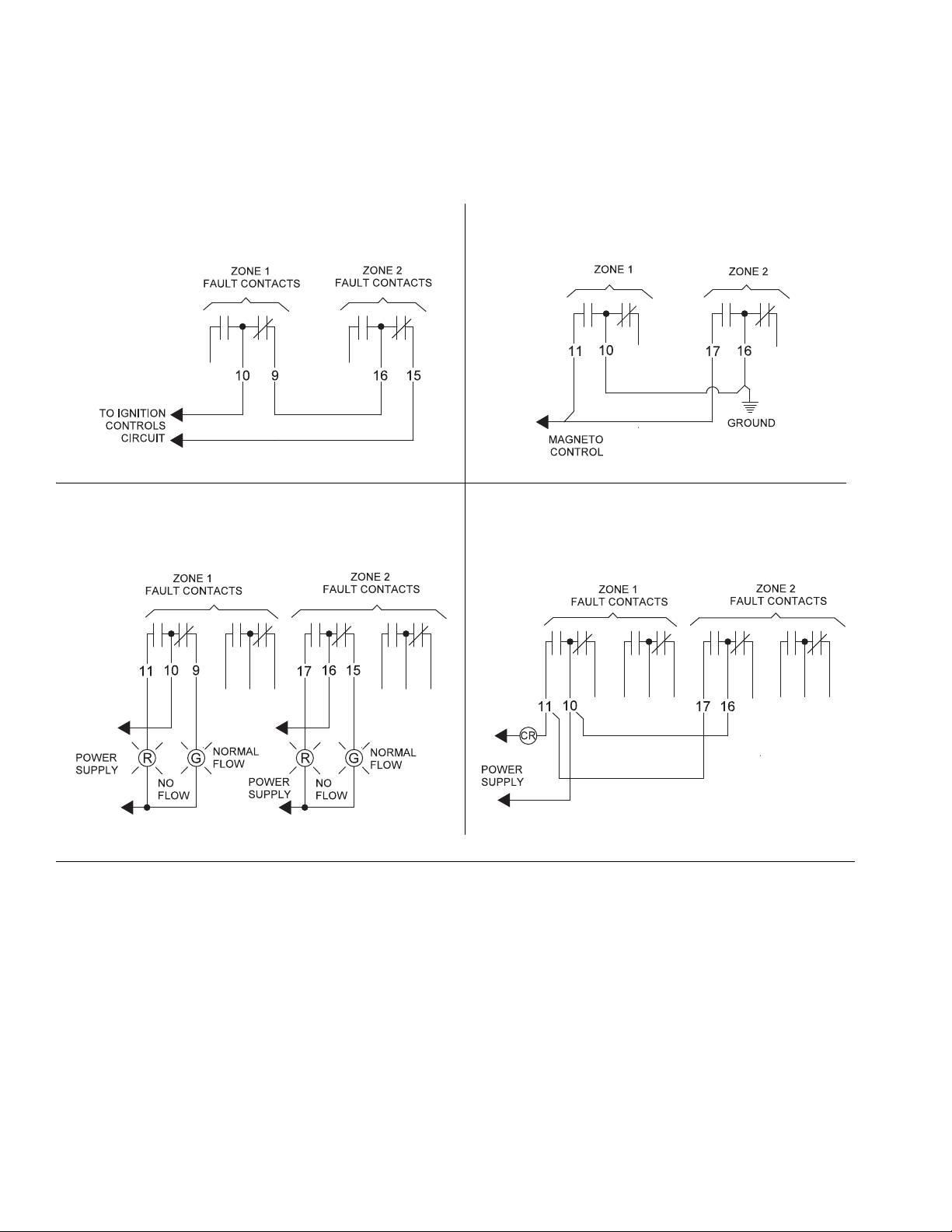
Ignition Shutdown Magneto Grounding
External Flow/No Flow Lights Energize External Load (relay coil, etc.)
Terminals 15 - 20, Zone 2 Fault Relay:
Relay data for Zone 2 is the same as for Zone 1. Pole “A” (for Zone 2) uses terminals 15 (nc), 16 (com) and 17 (no).
Pole “B” (for Zone 2) uses terminals 18 (nc), 19 (com) and 20 (no). (See F
IG. 4.)
F
IG. 4: Wiring Examples when Zone 1 and Zone 2 are used.
6 313903C
Page 7
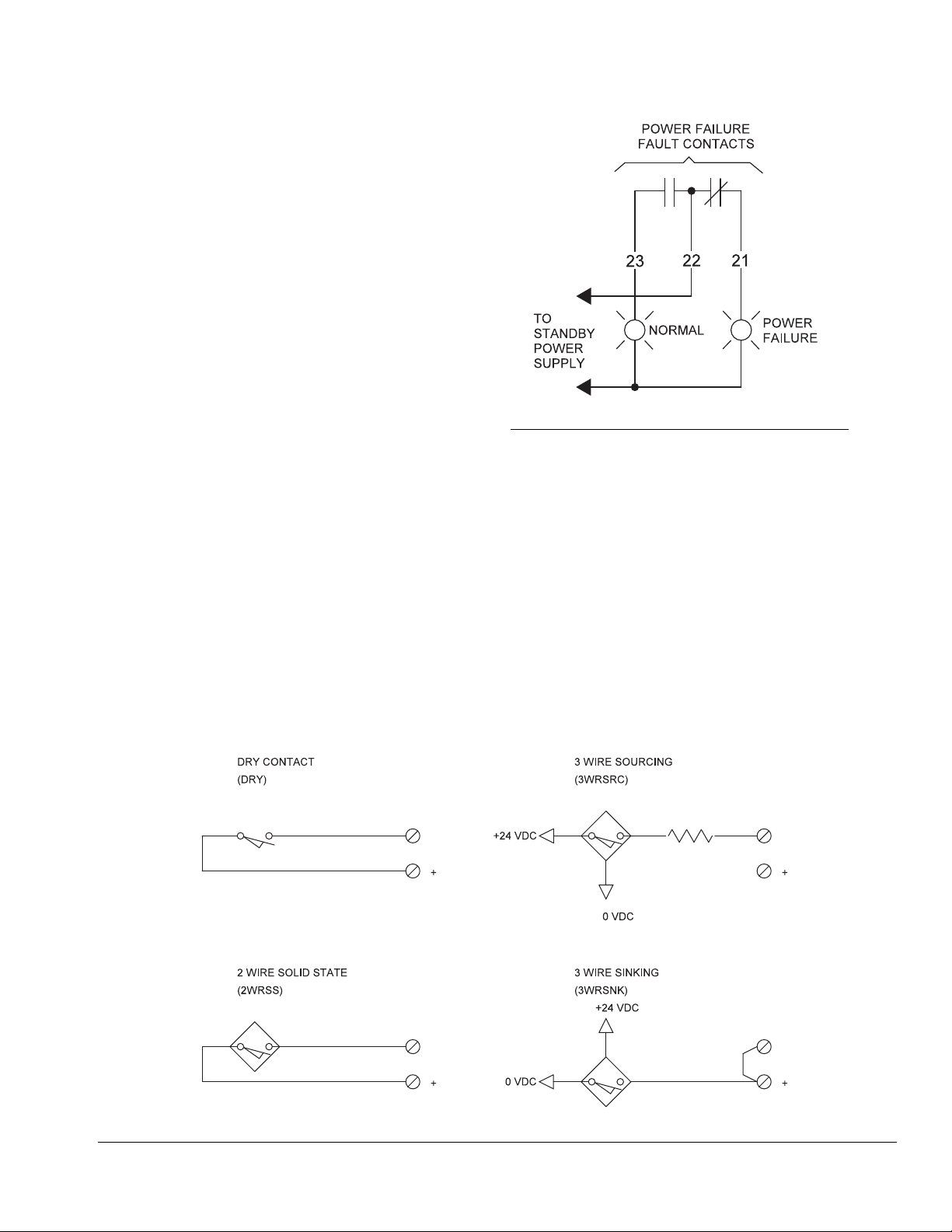
Terminals 21 - 23, Power Failure Relay:
The power-fail relay is a single-pole, single-throw
(SPST) relay rated for 0.5 ampere at 125 VAC or 1.0
ampere at 30 VDC. Terminals are to Form “C” contacts:
21 (nc), 22 (com) and 23 (no). This relay will be energized as long as power supply voltage is active (F
IG. 5).
Terminal Strip Left Side Bottom - Sensor Inputs
Terminals Sensor Inputs
Installation
FIG. 5: Power Failure Relay Connections
+25 & -26 For Factory Use
+27 & -28 Tachometer Input
+29 & -30 Bypass Zone 2
+31 & -32 Bypass Zone 1
+33 & -34 Reset Alarm
+35 & -36 Cycle Switch Zone 2
+37 & -38 Cycle Switch Zone 1
F
IG. 6: Typical Input Devices
313903C 7
Page 8
Installation
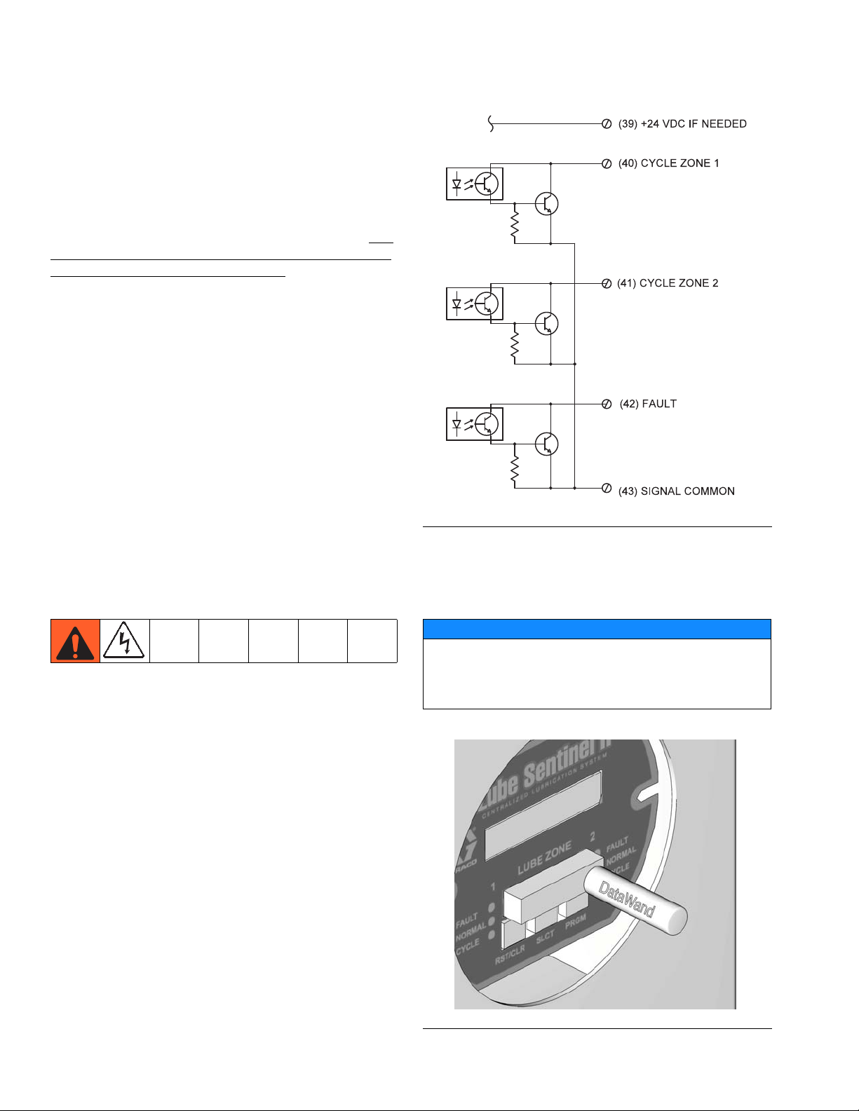
Terminal Strip Left Side TOP Open Collector Outputs
These outputs are open collector, floating TTL outputs.
There are no protection devices on these drivers. If the
transistor output is connected directly to +24 volts with
no load, these devices may be damaged. These drivers
are optically isolated from the local power supply and
their commons are floating. To utilize these drivers, Terminal 43 must be connected to the common of the voltage supply for the device being driven (such as a PLC
input power supply, input common).
Terminals Sensor Inputs
39 +24 VDC Out
40 Sensor Echo Zone 1
41 Sensor Echo Zone 2
42 System Fault
43 Floating Drive Common
Safety Set (optional)
The Safety Set is a plug-in option that allows the operator to manually activate the function buttons from outside the enclosure.
1. Disconnect all power to the monitor.
2. Verify that the module is properly aligned and all
pins are in their proper sockets.
3. Place the magnetic Datawand over the Safety Set
target above the desired button to activate the function buttons (F
The Datawand activates the sensor through the window and keeps it activated until the Datawand is
removed.
IG. 8).
F
IG. 7
NOTICE
Use caution when handling and storing the Datawand. It
emits a strong magnetic field. Bringing the Datawand
near magnetic media found on credit cards, floppy diskettes, or audio tape could destroy stored information!
F
IG. 8
8 313903C
Page 9
Installation
Serial Communication
Remote communication (up to 100 feet) can be
achieved using an RS-232-type port.
Information can be read from, or written to the Sentinel II
by a personal computer (or other intelligent device). This
communication is a master/slave protocol with the Sentinel II as the slave and the PC as the master.
NOTE: With the exception of a sign-on message when
powered up, the slave will not send any data or information unless requested by the master.
• Data is sent across the serial port as ASCII characters with leading zeros suppressed.
• A BYTE can be up to 3 characters.
• An INTERGER can be up to 5 characters.
• Each command and each response is terminated
with a carriage return (CR) (ASCII - Hexadecimal
0D or Decimal 13)
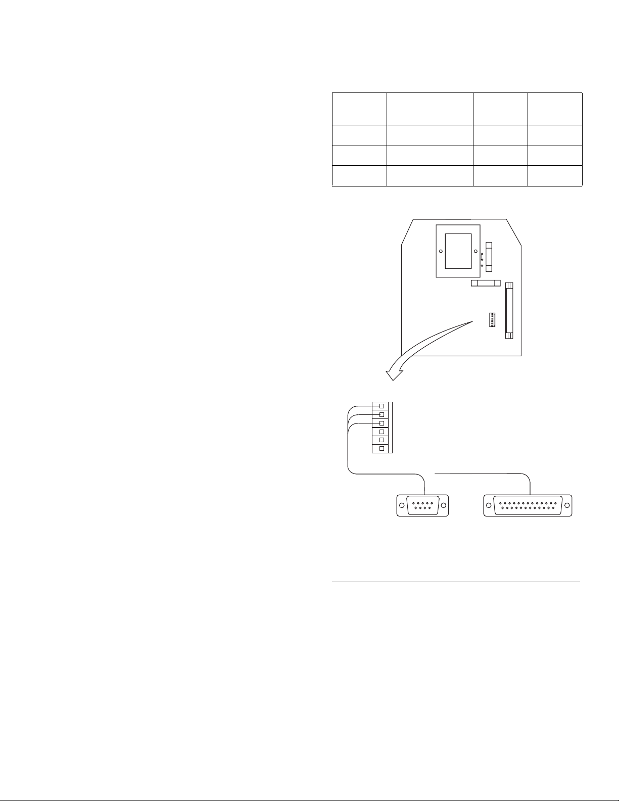
Table 1: Serial Pin Data
Pin # Description
1
2
3
Signal Ground 5 7
Read Data 2 3
Send Data 3 2
DB-9F
1
SERIAL
6
PC
J1
PC
DB-25F
• If the data is not presented in the correct format, the
command is not executed. Note that a “read” should
be made after doing a “write” to verify the proper
action has taken place.
NOTE: Changes made through the serial link are active
but not permanent until the “save to E
2
” command (WC)
is issued. If the WC command is not issued, turning the
power off and on restores the originally saved operating
parameters. See page 26 for recommended, user supplied, communication port connectors.
Serial Communication Wiring
• The Serial Communications are wired through a
6-point header on 0.1 inch centers (F
• Only three pins (1 - 3) are used (See Table 1).
• The other end of this cable may be connected to a
personal computer.
✓ Pin 1 (nearest to the transformer) is the signal
ground.
IG. 9).
F
IG. 9
SERIAL PORT PLUG
1 SIG COMMON
2 READ DATA (OUTPUT)
3 XMIT DATA (INPUT
4
5
6
2 RCV DATA (INPUT)
3 XMIT DATA (INPUT)
5 SIGNAL GROUND
TO PC SERIAL PORT
2 XMIT DATA (OUTPUT)
3 RCV DATA (INPUT)
7 SIGNAL GROUND
✓ Pin 2 is an output that connects to received data
at PC.
✓ Pin 3 is an input that connects to transmit data
of the PC.
313903C 9
Page 10

Component Identification
A
B
C
D
D
EE
F
F
G
Component Identification
F
IG. 10
Control Buttons
Operation and programming are controlled through the
use of three buttons located on the front display panel.
A RST/CLR button: In programming mode, used to reset or
clear a function
B SLCT button: In programming mode, toggles through field
options.
C PRGM button: In programming mode, used to enter
programing field.
Zone LEDs
There are three LED’s per zone for quick visual status
reporting.
D RED LED: Lites any time a zone is in fault.
E GREEN LED: Lites if a zone has its alarm active and
system is normal.
NOTE: Absence of either red or green lit LED’s indicates
that associated zone alarms are disabled.
F YELLOW LED: Echoes the cycle switch sensor status and
is lit when the switch is closed.
LCD Display - G
Displays information in one of three ways. Any of these
can be selected by pressing the SLCT button (B). The
LCD displays letter codes to identify the chosen display.
• “I” (Instantaneous): Displays the lube displacement
(over a 24 hour period) based on the time interval
between the last two cycles of the divider valve.
This time and the amount of lube delivered by one
cycle of the divider valve are factored together to
determine the 24-hour displacement.
• “A” (Average): Displays the lube displacement (over
a 24 hour period) based on the amount of time
required to complete ten cycles of the divider valve.
• “T” (Total): Displays the total amount of lubricant
that has been displaced.
The value is determined by multiplication of the
divider valve delivery by the number of times the
valve has cycled. This number is automatically
stored in memory upon completion of every ten minutes operation.
10 313903C
Page 11

General Feature Information
General Feature Information
Tachometer
Displays actual engine/compressor shaft speed (RPM).
A flashing asterisk indicates the tachometer is enabled.
A second LCD line displays the normal target operating
speed.
An ON/OFF indication displays to indicate when alarm
monitoring is active.
It is possible to override the active alarms when the
tachometer is enabled and drive mechanism is operating a minimal speed, by pressing the RST/CLR button
until the machine accelerates to 50% of it’s normal operating speed. At that point, the alarm override ceases,
allowing proportional alarmed startup of the equipment.
Enabled alarms stay active through all ranges of input
rpm until they are manually reset after the machine has
decelerated from 50% of its normal operating speed.
NOTE: When the alarm override is active, a letter “T”
and the word “OFF” will be displayed on the LCD.
When the RST/CLR button is pushed to reset Sentinel
II, the display resets back to 0 (zero). However, if the display is in the totalized mode (identified by the letter “T”)
pressing RST/CLR resets the totals back to the last
stored value. Care should be taken when resetting a
fault to ensure that the display is not in the totalized
mode. Resetting the fault will also reset the total accumulated usage.
Fault Relay
There are three fault relays. One is used as a Power
Monitor and two are used as Zone Fault relays.
The Power Monitor Relay is a single-pole, double-throw
relay with Form C contacts. It energizes approximately 5
seconds after power is applied and stays energized as
long as power is available to the monitor. When power is
removed from the system, the relay deenergizes immediately.
Zone Fault Relays are enabled during programming.
Each Zone Fault Relay is a double-pole, double-throw
relay with two Form C contacts that change state when
their associated zone goes into fault. The Zone Fault
Relay may be programmed to either pick or drop when a
fault is detected, allowing for fail-safe operating if
desired.
A system fault TTL output is also available to annunciate
faults. It is linked with programming for relay energization settings.
Resetting Faults
Faults may be reset in several ways:
• Manually reset at the monitor by pressing the
RST/CLR button.
• Using the “Safety Set” target (see Safety Set,
page 8).
• Electrically by closing the remote reset contacts.
Zone Enable/Disable
Zones are enabled during programming. A zone may be
disabled initially by programming the zone “OFF” or by
temporarily placing an enabled zone in “BYPASS” mode
(Terminals 29, 30, 31 and 32).
Closing the contacts for “ZONE BYPASS” disables a
zone from any fault time-outs. The zone display shows
the word “BYPASS” to indicate this condition.
When the bypass has been removed, active monitoring
of the zone continues. If the alarm is enabled, the alarm
time-out will restart.
313903C 11
• Serial Port commands (see Serial Communication, page 9).
Page 12

Programming the Lube Sentinel II Monitor
Cycle Switches and Other Sensor Inputs
All sensor inputs should be dry contact type. Refer to
F
IG. 6, page 7. and Technical Data, page 26.
Cycle switch TTL outputs are provided for each zone to
echo the status of the sensor input from the divider valve
or other device. The output conducts current when the
sensor contacts are open. When the sensor contacts
close, the output shuts off.
NOTE: These outputs should not be used for cycle rates
faster than one pulse per second. Output pulses may be
missed if higher cycle rates are used.
These outputs are not short-circuit protected (100mAmax). Improper connection could result in damage to
these outputs. (See Circuit Board Connections, beginning on page 4.)
Programming the Lube Sentinel II Monitor
Operation of the Lube Sentinel II is controlled through
three buttons located on the front display panel.
Buttons are labeled:
• RST/CLR - reset and/or clear
• SLCT - select
• PGRM - program
After the Lube Sentinel is programmed, it is ready for
normal operation in the monitor mode. In this mode the
Lube Sentinel II monitors the lubricant delivery and provides associated data on the LCD display.
Programming Overview
NOTE: The following Programming Overview instructions are provided as a quick guide, only. Detailed,
Step-By-Step Programming instructions are provided on
page 14.
Entering Data
There are four main selections within the programming
field:
• Configuration? Zone 1: Sets Zone 1 parameters
• Configuration? Zone 2: Sets Zone 2 parameters
• Serial Port: Sets parameters for serial communica-
tions to PC
• Global Settings: Specifies how the monitor reacts
to faults and how relays are energized or deenergized
12 313903C
Page 13

Programming the Lube Sentinel II Monitor
RST/CLR SLCT
PRGM
Press PRGM button to
enter programming field.
Press SLCT button to toggle between four fields.
CONFIGURATION?
CONFIGURATION? SERIAL PORT
GLOBAL SETTINGS
1
2
- ENABLE ZONE
- UNITS OF MEASURE
- PORT TOTAL
- FAULT SETUP
- FLOW ALARM ON
- LOW FLOW SET
- HIGH FLOW SET
- ENABLE TACH
- SET # PULSES/REV
- SET NORMAL RPM
- ENABLE ZONE
- UNITS OF MEASURE
- PORT TOTAL
- FAULT SETUP
- FLOW ALARM ON
- LOW FLOW SET
- HIGH FLOW SET
- ENABLE TACH
- SET # PULSES/REV
- SET NORMAL RPM
- BAUD RATE
- WORD LENGTH
- STOP BITS
- PARITY
- FAULTS TO SKIP
(Nuisance Faults)
- INVERT RELAYS
RST/CLR
SLCT
PRGM
3
Options
Press PRGM button to scroll
through field options.
RST/CLR
SLCT
PRGM
RST/CLR
SLCT
PRGM
Press SLCT button to toggle through choices for
selected options.
4
(Fault Relay Logic)
Fields
F
IG. 11
For the following instructions, refer to FIG. 11.
1. Press PRGM button once to enter programming
field.
2. Press SLCT button to move from CONFIGURA-
TION?ZONE1, to CONFIGURATION?ZONE2, to
SERIAL PORT, and to GLOBAL SETTINGS.
3. When the desired field is selected, pressing the
PRGM button scrolls through the options within that
field.
4. Pressing the SLCT button toggles through the
choices available for the selected option.
Saving Program Changes
1. When the display shows CONFIGURATION?ZONE1, CONFIGURATION?ZONE2,
SERIAL PORT, or GLOBAL SETTINGS, press the
RST/CLR button to place the Sentinel II in the monitor mode.
2. A prompt will ask if any changes should be saved.
The default is NO. To save the changes, press the
SLCT button to change to YES.
3. Then press the PRGM button.
NOTE: Pressing any other button when NO is showing
will erase any changes indicated and leave all settings
as they were before entering the programming function.
313903C 13
Page 14

Step-By-Step Programming Instructions
Step-By-Step Programming Instructions
The following instructions are listed in order of appearance. To bypass a selection, press the SLCT button until
the desired selection displays.
Configuration?Zone1
1. Press PRGM button to enter the programming
mode.
CONFIGURATION?ZONE1 displays.
2. With CONFIGURATION?ZONE1 displayed, press
the PRGM button again to enter the options for
Zone 1.
• Enable Zone: The first option will be to enable
the zone.
a. Press SLCT button to toggle between YES
and NO. If the zone is not to be enabled, no
further options will be asked for. A disabled
zone appears as dashes across the screen
and will not generate any faults. (F
b. Press PGRM again to advance to the next
programming option.
IG. 12).
• Port Total: The total quantity of lubricant vol-
ume provided to lubrication points.
This input is necessary for calibrating the Sentinel II for the lubricant volume required for one
cycle of the divider valve assembly.
To determine this number:
a. Locate the divider valve assembly that has
the lube system cycle switch mounted on it.
b. Add the output volume numbers stamped in
the upper right corner of each of the assembly’s valve sections (F
a 10T or 10S section. etc.).
IG. 13) (i.e., the 10 from
FIG. 13
F
IG. 12
• Units of Measure: Choose one - ounce, pints,
gallons, liters, milliliters or counts.
a. Press the SLCT button to toggle between the
displayable units.
b. When choice displays on screen, push
PGRM button to advance to the next programming option.
NOTE: Each zone can read out in different units.
14 313903C
c. Double the sum quantity.
d. Subtract any individual output value(s) con-
nected to an output line that is not feeding a
lubrication point or another secondary feeder
assembly (i.e., a line returning oil to the reservoir, or any other destination that is not a
rotating/moving lubrication point).
This number is the Port Total.
Page 15

Step-By-Step Programming Instructions
e. Press and hold the SLCT button to increase
the value until the Port Total from step d,
(page 14) displays. (9999 is the maximum
amount allowed in this field.)
Use the RST/CLR button to decrease the
value.
f. Release the button when the Port Total is
shown on the display.
NOTE: Changing the Port Total on the display, changes
the displayed alarm rate. Always reset the alarm rate
after altering the Port Total.
g. Press the PGRM button to advance to the
next programming option.
• Fault Setup: Choose one - INTERLOCKED,
INDEPENDENT or DISABLED
a. Press SLCT button to toggle between
choices.
✓ INERLOCKED: ties the two zones into a
first alarm indication only.
✓ INDEPENDENT: each zone is allowed to
register a fault when its rate limit has been
exceeded. This allows the Sentinel II to be
used to monitor two separate systems.
✓ DISABLED: no fault will be generated from
that zone.
NOTE: Changing the status of one alarm zone will automatically change the status of the other zone.
• Low Flow Set: Appears if LOW FLOW or HI
and LOW FLOW is selected. (If HIGH FLOW
only was selected, skip to the HIGH FLOW SET
section.)
The alarm is based on the minimum usage rate
(Low Flow) per 24 hours. Should the usage drop
below that value, the zone will go into fault and
display the letter “L” in the zone status line for
F
IG. 14
that zone (F
IG. 14).
a. Press and hold the SLCT button to increase
the value and set the Low Flow rate. (9999 is
the maximum amount allowed in this field.)
Use the RST/CLR button to decrease the
value.
b. Release the button when the Low Flow rate is
shown on the display.
b. When choice displays, press the PGRM but-
ton to advance to the next programming
option.
• Flow Alarm On: Choose one - LOW FLOW,
NOTE: If the HI and LOW FLOW is selected, the amount
entered, cannot exceed 85% of the HIGH FLOW value.
c. Press the PGRM button to advance to the
next programming option.
HIGH FLOW or HI and LOW FLOW alarms.
a. Press the SLCT button to toggle between
choices.
b. When choice displays, press the PGRM but-
ton to advance to the next programming
option.
313903C 15
Page 16

Step-By-Step Programming Instructions
• High Flow Set: Appears if HIGH FLOW or HI
and LOW FLOW is selected. (If LOW FLOW
only was selected, skip to the ENABLE TACH
section.)
The alarm is based on the maximum usage rate
(High Flow) per 24 hours. Should the usage
exceed that value, the zone will go into fault and
display the letter “H” in the zone status line for
F
IG. 15
that zone (F
IG. 15).
a. Press the SLCT button to toggle between
choices.
If the tachometer is not to be enabled, select
NO. No further options will be asked for the
zone.
Enabling the tachometer (selecting YES) will
add a + (plus) sign to the display screen to
indicate that alarm times are being adjusted
(F
IG. 16).
NOTE: The + (plus) sign also appears if
Faults Skip, option 2 or 3, is chosen, page 18.
Tachometer parameters selected are programmed common to both zones.
Settings made for Zone 1 are automatically
entered for Zone 2.
a. Press and hold the SLCT button to increase
the value and set the High Flow rate. (9999 is
the maximum amount allowed in this field.)
Use the RST/CLR button to decrease the
value.
b. Release the button when the Low Flow rate is
shown on the display.
NOTE: If the HI and LOW FLOW is selected, the amount
entered, cannot drop below 15% of the LOW FLOW
value.
c. Press the PGRM button to advance to the
next programming option.
• Enable Tach: Choose one - YES or NO.
FIG. 16
b. Press the PGRM button to advance to the
next programming option.
• Set # Pulses/Rev: Program the number of
pulses the sensor will see in one revolution of
the pump drive mechanism. The tachometer
input is based on this number.
a. Press and hold the SLCT button to increase
the pulse count. (20 pulses per shaft revolution maximum.)
Use the RST/CLR button to decrease the
value.
16 313903C
Page 17

Step-By-Step Programming Instructions
b. Release the button when the pulse count is
shown on the display.
c. Press the PGRM button to advance to the
next programming option.
• Set Normal RPM: Programs the normal speed
at which the pump drive mechanism is expected
to operate.
a. Press and hold the SLCT button to increase
the RPM to a specified maximum. (See Table
2. Maximum RPM Pulses/Rev, page 17 for
limits.)
Use the RST/CLR button to decrease the
RPM’s. (The minimum selectable speed is 50
rpm.)
b. Release the button when the pulse count is
shown on the display.
Table 2. Maximum RPM for Pulses/Rev.
A drive is expected to operate at 100
rpm. The LOW FLOW rate for Zone 1 is
set to 30 pints per day. If the drive is
reduced to 75 rpm (or 75%), the LOW
FLOW fault point is adjusted down to
22.5 pints per day (also 75%). Note that
the minimum and maximum adjusted
values are +/- 50% (45 pints at 150 rpm
and 15 pints at 50 rpm).
c. Press the PGRM button. Since there are no
additional options, the display returns to the
start of the CONFIGURATION?ZONE1 selection.
3. Push the SLCT button to toggle to CONFIGURATION?ZONE2.
NOTE: Pressing RST/CLR at this time exits the programming mode and asks if the changes made should
be permanent. Use the SLCT button to choose the
desired response and press the PRGM button to exit the
programming field and return back to the monitor mode.
Pulse/Rev RPM Max Pulses/Rev RPM Max
1 5000 11 454
2 2500 12 416
3 1666 13 384
4 1250 14 357
5 1000 15 333
6 833 16 312
7 714 17 294
8 625 18 277
9 555 19 263
10 500 20 250
NOTE: The Sentinel II program allows the
machine and lubricator pump speed to vary
without causing a high or low lube fault. As the
actual measured rpm varies from the target normal rpm, the fault rate will also vary by the same
deviation percentage. The maximum deviation
from the target fault setpoints is +/- 50%.
EXAMPLE:
Configuration?Zone2
The method of configuring Zone 2 is the same as Zone
1. If you 2 does not need to be configured, press the
SLCT button to toggle to Serial Port.
Serial Port
NOTE: If a Serial Port is not being used, press the SLCT
button to toggle to Global Settings.
To configure the Serial Port settings:
1. Press PRGM button to enter the options for the
Serial Port.
• Baud Rate: Choose one rate - 1200, 2400,
4800 and 9600.
a. Press the SLCT button to toggle between
choices.
b. When choice displays, press the PGRM but-
ton to advance to the next programming
option.
• Word Length: Permanently set to 8 bits.
Press the PGRM button to advance to the next
programming option.
313903C 17
Page 18

Step-By-Step Programming Instructions
• Stop Bits: Choose one: 1 or 2 bits.
a. Press the SLCT button to toggle between
choices.
b. When choice displays, press the PGRM but-
ton to advance to the next programming
option.
• Parity: Choose one: ODD, EVEN and SELECT.
a. Press the SLCT button to toggle between
choices.
b. When choice displays, press the PGRM but-
ton to advance to the next programming
option. Since there are no additional options,
the display returns to the start of the Serial
Port selection.
2. Push the SLCT button to toggle to the Global Set-
tings.
Global Settings
1. Press PRGM button to enter the options for Global
Settings.
• Invert Relays (fault relay logic): Allows selection
of whether the zone fault relays and the TTL
output will energize or deenergize when a fault
is registered.
Choose either YES or NO:
a. Press the SLCT button to toggle between
choices.
✓ NO: The fault relay contacts will be deenergized during normal system operation and
energize upon a fault.
✓ YES: The fault relay contacts will be energized during normal system operation and
deenergize upon a fault.
b. When choice displays, press the PGRM but-
ton to advance to the next programming
option. Since there are no additional options,
the display returns to the start of the Global
Settings selection.
2. Push the SLCT button returns to the CONFIGURA-
TION?ZONE1 option.
• Faults to Skip (nuisance faults): Allows Senti-
nel II to ignore nuisance faults. It will delay logging a fault until one, two or three consecutive
faults are received.
Choose either 1, 2 or 3:
a. Press the SLCT button to toggle between
choices.
✓ 1: The normal operation setting uses 1.
Faults on the first occurrence of a time out.
✓ 2 or 3: If 2 or 3 is selected a + (plus) sign
will display in the monitor window to indicate
that alarm times are being dynamically
adjusted.
NOTE: The + (plus) sign also appears if the
Tachometer option is chosen, page 16.
b. When choice displays, press the PGRM but-
ton to advance to the next programming
option.
AUTOMATIC SYSTEM ACTIVATION HAZARD
Unexpected activation of the system could result in serious injury, including skin injection and amputation.
This device has an automatic timer that activates the
pump lubrication system when power is connected or
when exiting the programming function. Before you
install or remove the Lube Sentinel II Monitor from the
system, disconnect and isolate all power supplies and
relieve all pressure.
Exit/Save Changes
1. Press RST/CLR button at any time moves to the exit
routine.
2. You will be prompted to Save Changes. The default
response is NO.
3. If all modifications to the Sentinel II are satisfactory
and ready to be permanent, press the SLCT button
to change the response to YES.
18 313903C
Page 19

4. Press the PGRM button.
When the Sentinel II returns to the monitor mode
and updated with the new, saved changes.
NOTE:
• Pressing any other button, or leaving the response
set to NO, erases and does NOT save changes.
Sentinel II returns to the original setup configuration.
• Once the changes have been saved, pressing
RST/CLR button will not undo the new setup configuration.
Step-By-Step Programming Instructions
313903C 19
Page 20

Definitions
Definitions
Data Definition
R1z
Read settings of Zone 1 or 2. The z is set to either 1 or 2. The returned message is a data
structure arranged in the following order:
a. BYTE - 0 or 1 indicates whether the zone is enabled
b. BYTE - Unit of measurement on the display
0 = Ounces
1 = Pints
2 = Gallons
3 = Liters
4 = Millimeters
5 = Counts
c. BYTE - Interlock of alarms
0 = Alarm Disabled
1 = Alarm Zones Interlocked (First Alarm)
2 = Alarms Independent
d. BYTE - Alarm Generation
0 = Low Flow Alarm Only
1 = High Flow Alarm Only
2 = Both Low and High Flow Alarms
e. BYTE - 0 or 1 indicates whether the Tachometer is enabled.
f. INTEGER - Block Total
g. INTEGER - Low Flow Limit for Alarm
h. INTEGER - High Flow Limit for Alarm
i. INTEGER - Tachometer Setting for Normal RPM
j. BYTE - Tach Pulses per RPM
Read the current status of Zone 1 or 2. The z is set to either 1 or 2. The returned message
is a data structure arranged in the following order:
a. BYTE - Cycle Position. Indicates if the input is opened or closed (0 or 1).
R2z
R3 INTEGER - Read Current RPM.
R4 BYTE - Read the number of faults skipped before signaling a fault (value = 1, 2 or 3).
BYTE - Read if relay output is inverted.
R5
b. INTEGER - Cycle Timer. Running time in 0.1 seconds since start of cycle.
c. INTEGER - Last Cycle Time. Time of the last cycle.
d. INTEGER - Cycle Count. Number of cycles since last reset.
e. BYTE - Fault Status (N/F) for Normal or Fault.
0 = Normal
1 = Inverted
20 313903C
Page 21

Set Zone Enable/Disable.
Definitions
W1zx
W2zx
W3zx
a. BYTE z = 1 or 2 for the zone being addressed.
b. BYTE x = 0 or 1 to disable or enable the zone.
Set zone unit of measure.
a. BYTE z = 1 or 2 for the zone being addressed.
b. BYTE x = selects units to display.
0 = Ounce
1 = Pints
2 = Gallons
3 = Liters
4 = Millimeters
5 = Counts
Set Zone Interlock.
a. BYTE z = 1 or 2 for the zone being addressed.
b. BYTE x = Interlock of alarms.
0 = Alarm Disabled
1 = Alarm Zones Interlocked (First Alarm)
2 = Alarms Independent
Set high/low alarm limits.
a. BYTE z = 1 or 2 for the zone being addressed.
W4zx
W5zx
W6zxxxx
W7zxxxx
W8zxxxx
W9xxxx
b. BYTE x = Alarm generation.
0 = Low Flow Alarm Only.
1 = High Flow Alarm Only.
2 = Both Low and High Flow Alarms.
BYTE - Turns the Tachometer On or Off.
0 = Disabled
1 = Enabled
Set the port total.
a. BYTE z = 1 or 2 for the zone being addressed.
b. INTEGER xxxx = 5 to 9999 (thousandths of a cu-in.).
Set Low Flow Alarm.
a. BYTE z = 1 or 2 for the zone being addressed.
b. INTEGER xxxx = 5 to 65535 per sentinel specifications. Low Flow Alarm should
be at least 10% less than the High Flow Alarm.
Set High Flow Alarm.
a. BYTE z = 1 or 2 for the zone being addressed.
b. INTEGER xxxx = 5 to 65535 per sentinel specifications. High Flow Alarm
should be at least 10% greater than the Low Flow Alarm.
Set normal tachometer speed.
INTEGER xxxx = 50 to 5001
313903C 21
Page 22

Definitions
WAxx
Set tachometer pulses per revolution.
INTEGER xx = 1 - 32
WB Reset Faults.
WC Save Data to EEPROM. Programming changes become permanent.
WDx Set the fault count to alarm on, where x = 1, 2, or 3.
Set the polarity of the fault relays.
WEx
0 = No. Relays not inverted, normally deenergized, energize on a fault.
1 = Yes. Relays are inverted, normally energized, deenergize on a fault.
22 313903C
Page 23

Dimensions
0.5 in.
(12.7 mm)
0.62 in.
(15.9 mm)
6.25 in. (158.7 mm)
5.00 in. (127.0 mm)
4.00 in. (101.6 mm)
8.75 in.
(222.2
mm)
8.25 in.
(209.5 mm)
0.25 in.
(6.3 mm)
0.312 in. (7.9 mm)
Diameter
9.50 in.
(241.3 mm)
JIC Model: 562870
Dimensions
FIG. 17
313903C 23
Page 24

Dimensions
5.37 in. (136.5 mm)
0.87 in. (22.2 mm)
Diameter conduit
connection
(2 each side)
ti14405
Model: 562870
FIG. 18
24 313903C
Page 25

Model: 562871
6.875 in. (174.6 mm)
8.5 in. (215.9 mm)
7.75 in.
(196.9 mm)
6.00 in.
(152.4 mm)
0.875 in.
(22.2 mm)
0.813 in.
(20.6 mm)
6.5 in. (165.1 mm)
1/2 N.P.T. conduit connection, 2 each side
ti14406
Dimensions
FIG. 19
FIG. 20
313903C 25
Page 26

Technical Data
Technical Data
Input Power Requirements 115VAC - 100 ma; 230VAC - 50 ma
24 - 30VDC - 200 ma
Fuses: FU-1 and FU-2 Use Medium Lag Fuses Only. Do
NOT use Fast Acting Fuses.
Proximity Switch Pulse Inputs 24VDC - 12 ma each
Tach Sensor Pulse Input 24VDC - 12 ma
Zone Bypass and Alarm Inputs 24VDC - 12 ma each
Relay Outputs Contact Ratings
Rated Load 0.5Amp at 125VAC
Maximum Carry Current 2Amp
Maximum Operating Voltage 250VAC
Maximum Switching Capacity 62.5 VA, 60W
Minimum Permissible Load
Relay Coil Current Consumption 70ma @ 115VAC
Communications Port Connector* TTL Outputs (non-fused) 24VDC max 100ma max.
Maximum Pulse Rate 300 per minute @ 50% duty
Maximum Cycle Time 10.9 minutes
Ambient Temperature Range† - 4°F to +158°F (- 20°C to +70°C)
Net Weight
Model: 562870 8.4 lbs (3.8 kg)
Model: 562871 18.3 lbs (8.3 kg)
1/4 in. x 1 in.: 0.5 AMP, 250VAC
5 mm x 20 mm: 0.5 AMP, 250VAC (buss# GMA-500 or
equivalent)
1Amp at 30VDC
220VDC
10
µA 10mVDC
40ma @ 230VAC
150ma @ 24VDC
*User Supplied Component: Graco recommends
• Waldom-Molex Housing #22-01-3067 (or alternate part: AMP Housing #770602-6)
• Waldom-Molex Pins #08-50-01114 (or alternate part: AMP PINS #770666-1
† Do not mount in direct sunlight. Prolonged exposure will damage LCD.
26 313903C
Page 27

Notes
Notes
313903C 27
Page 28

Graco Standard Warranty
Graco warrants all equipment referenced in this document which is manufactured by Graco and bearing its name to be free from defects in
material and workmanship on the date of sale to the original purchaser for use. With the exception of any special, extended, or limited warranty
published by Graco, Graco will, for a period of twelve months from the date of sale, repair or replace any part of the equipment determined by
Graco to be defective. This warranty applies only when the equipment is installed, operated and maintained in accordance with Graco’s written
recommendations.
This warranty does not cover, and Graco shall not be liable for general wear and tear, or any malfunction, damage or wear caused by faulty
installation, misapplication, abrasion, corrosion, inadequate or improper maintenance, negligence, accident, tampering, or substitution of
non-Graco component parts. Nor shall Graco be liable for malfunction, damage or wear caused by the incompatibility of Graco equipment with
structures, accessories, equipment or materials not supplied by Graco, or the improper design, manufacture, installation, operation or
maintenance of structures, accessories, equipment or materials not supplied by Graco.
This warranty is conditioned upon the prepaid return of the equipment claimed to be defective to an authorized Graco distributor for verification of
the claimed defect. If the claimed defect is verified, Graco will repair or replace free of charge any defective parts. The equipment will be returned
to the original purchaser transportation prepaid. If inspection of the equipment does not disclose any defect in material or workmanship, repairs will
be made at a reasonable charge, which charges may include the costs of parts, labor, and transportation.
THIS WARRANTY IS EXCLUSIVE, AND IS IN LIEU OF ANY OTHER WARRANTIES, EXPRESS OR IMPLIED, INCLUDING BUT NOT LIMITED
TO WARRANTY OF MERCHANTABILITY OR WARRANTY OF FITNESS FOR A PARTICULAR PURPOSE.
Graco’s sole obligation and buyer’s sole remedy for any breach of warranty shall be as set forth above. The buyer agrees that no other remedy
(including, but not limited to, incidental or consequential damages for lost profits, lost sales, injury to person or property, or any other incidental or
consequential loss) shall be available. Any action for breach of warranty must be brought within two (2) years of the date of sale.
GRACO MAKES NO WARRANTY, AND DISCLAIMS ALL IMPLIED WARRANTIES OF MERCHANTABILITY AND FITNESS FOR A
PARTICULAR PURPOSE, IN CONNECTION WITH ACCESSORIES, EQUIPMENT, MATERIALS OR COMPONENTS SOLD BUT NOT
MANUFACTURED BY GRACO. These items sold, but not manufactured by Graco (such as electric motors, switches, hose, etc.), are subject to
the warranty, if any, of their manufacturer. Graco will provide purchaser with reasonable assistance in making any claim for breach of these
warranties.
In no event will Graco be liable for indirect, incidental, special or consequential damages resulting from Graco supplying equipment hereunder, or
the furnishing, performance, or use of any products or other goods sold hereto, whether due to a breach of contract, breach of warranty, the
negligence of Graco, or otherwise.
FOR GRACO CANADA CUSTOMERS
The Parties acknowledge that they have required that the present document, as well as all documents, notices and legal proceedings entered into,
given or instituted pursuant hereto or relating directly or indirectly hereto, be drawn up in English. Les parties reconnaissent avoir convenu que la
rédaction du présente document sera en Anglais, ainsi que tous documents, avis et procédures judiciaires exécutés, donnés ou intentés, à la suite
de ou en rapport, directement ou indirectement, avec les procédures concernées.
Graco Information
For the latest information about Graco products, visit www.graco.com.
TO PLACE AN ORDER, contact your Graco distributor or call to identify the nearest distributor.
Phone: 612-623-6928 or Toll Free: 1-800-533-9655, Fax: 612-378-3590
All written and visual data contained in this document reflects the latest product information available at the time of publication.
Graco reserves the right to make changes at any time without notice.
For patent information, see www.graco.com/patents.
This manual contains English. MM 313903
Graco Headquarters: Minneapolis
International Offices: Belgium, China, Japan, Korea
GRACO INC. P.O. BOX 1441 MINNEAPOLIS, MN 55440-1441
Copyright 2009, Graco Inc. is registered to ISO 9001
www.graco.com
Revised November 2013
 Loading...