

Page 1
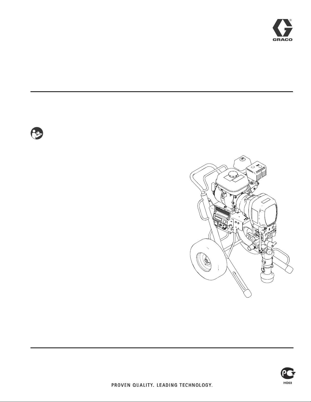
Repair
HTX 2030
313889B
-For Portable Airless and Air-Assisted Spraying of Water-Based Architectural Coatings with Base Coat Pump-
-For Airless Spraying Architectural Coatings and Paints with Top Coat Pump-
IMPORTANT SAFETY INSTRUCTIONS
Read all warnings and instructions in this manual. Save these instructions.
Model Number: 257369
Maximum Working Pressure:
Base Coat Pump: 1000 psi (69 bar, 6.9 MPa)
Top Coat Pump: 3300 psi (228 bar, 22.8 MPa)
Related Manuals
313888 - Operation (English)
313891 - Operation (French)
313893 - Operation (Spanish)
313892 - Repair (French)
313894 - Repair (Spanish)
313890 - Parts
313895 - HTX 2030 Flex Head and Pole Spray Applicator (English)
313896 - HTX 2030 Flex Head and Pole Spray Applicator (French)
313897 - HTX 2030 Flex Head and Pole Spray Applicator (Spanish)
310894 - Displacement Pump (Top Coat)
308491 - Texture Airless Spray Gun
313537 - HTX 2030 Applicator (English)
313603 - HTX 2030 Applicator (Chinese)
313908 - HTX 2030 Applicator (French)
313911 - HTX 2030 Applicator (Spanish)
ti13632a
Page 2

Contents
Contents
Contents . . . . . . . . . . . . . . . . . . . . . . . . . . . . . . . . . . 2
Warning . . . . . . . . . . . . . . . . . . . . . . . . . . . . . . . . . . 3
Component Identification - Sprayer . . . . . . . . . . . 5
Component Identification - Base Coat Applicator 6
Troubleshooting . . . . . . . . . . . . . . . . . . . . . . . . . . . . 7
Pressure Relief Procedure . . . . . . . . . . . . . . . . . . . 9
Repair . . . . . . . . . . . . . . . . . . . . . . . . . . . . . . . . . . . 10
Bearing Housing and Connecting Rod . . . . . . . 10
Drive Housing . . . . . . . . . . . . . . . . . . . . . . . . . . 12
Pinion Assembly / Clutch Armature / Clamp . . . 13
Clutch Housing . . . . . . . . . . . . . . . . . . . . . . . . . 17
Engine . . . . . . . . . . . . . . . . . . . . . . . . . . . . . . . . 17
Pressure Control . . . . . . . . . . . . . . . . . . . . . . . . 18
Displacement Pump . . . . . . . . . . . . . . . . . . . . . 22
Wiring Diagram . . . . . . . . . . . . . . . . . . . . . . . . . . . 24
Technical Data . . . . . . . . . . . . . . . . . . . . . . . . . . . . 25
Notes . . . . . . . . . . . . . . . . . . . . . . . . . . . . . . . . . . . . 26
Graco Standard Warranty . . . . . . . . . . . . . . . . . . . 28
2 313889B
Page 3
Warning
Warning
The following warnings are for the setup, use, grounding, maintenance, and repair of this equipment. The
exclamation point symbol alerts you to a general warning and the hazard symbol refers to procedure-specific risk. Refer back to these warnings. Additional, product-specific warnings may be found throughout the
body of this manual where applicable.
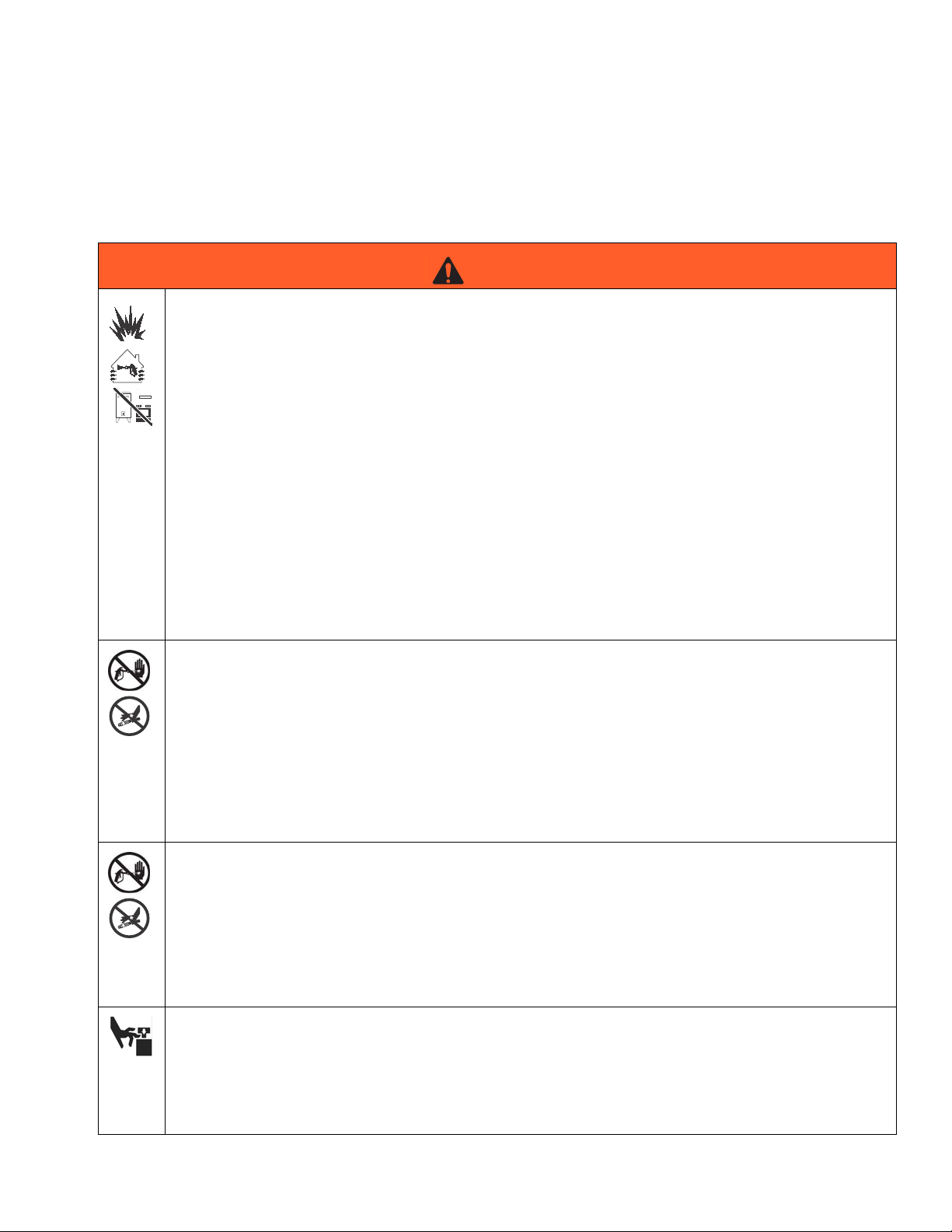
WARNING
FIRE AND EXPLOSION HAZARD
Flammable fumes, such as solvent and paint fumes, in work area can ignite or explode. To help prevent
fire and explosion:
• Use equipment only in well ventilated area.
• Do not fill fuel tank while engine is running or hot; shut off engine and let it cool. Fuel is flammable
and can ignite or explode if spilled on hot surface.
• When flammable liquid is sprayed or used for flushing or cleaning, keep sprayer at least 20 feet (6 m)
away from explosive vapors.
• Eliminate all ignition sources; such as pilot lights, cigarettes, portable electric lamps, and plastic drop
cloths (potential static arc).
• Keep work area free of debris, including solvent, rags and gasoline.
• Do not plug or unplug power cords, or turn power or light switches on or off when flammable fumes
are present.
• Ground equipment and conductive objects in work area. See Grounding instructions.
• Use only grounded hoses.
• Hold gun firmly to side of grounded pail when triggering into pail.
• If there is static sparking or you feel a shock, stop operation immediately. Do not use equipment
until you identify and correct the problem.
SKIN INJECTION HAZARD (SPRAY GUN)
High-pressure fluid from gun, hose leaks, or ruptured components will pierce skin. This may look like just
a cut, but it is a serious injury that can result in amputation. Get immediate surgical treatment.
• Do not point gun at anyone or at any part of the body.
• Do not put your hand over the spray tip.
• Do not stop or deflect leaks with your hand, body, glove, or rag.
• Do not spray without tip guard and trigger guard installed.
• Engage trigger lock when not spraying.
• Follow Pressure Relief Procedure in this manual, when you stop spraying and before cleaning,
checking, or servicing equipment.
SKIN INJECTION HAZARD (APPLICATOR)
High-pressure fluid from gun, hose leaks, or ruptured components will pierce skin. This may look like just
a cut, but it is a serious injury that can result in amputation. Get immediate surgical treatment.
• Do not point gun at anyone or at any part of the body.
• Do not put your hand over the spray tip.
• Do not stop or deflect leaks with your hand, body, glove, or rag.
• Follow Pressure Relief Procedure in this manual, when you stop spraying and before cleaning,
checking, or servicing equipment.
MOVING PARTS HAZARD
Moving parts can pinch or amputate fingers and other body parts.
• Keep clear of moving parts.
• Do not operate equipment with protective guards or covers removed.
• Pressurized equipment can start without warning. Before checking, moving, or servicing equipment,
follow the Pressure Relief Procedure in this manual. Disconnect power or air supply.
313889B 3
Page 4
Warning
WARNING
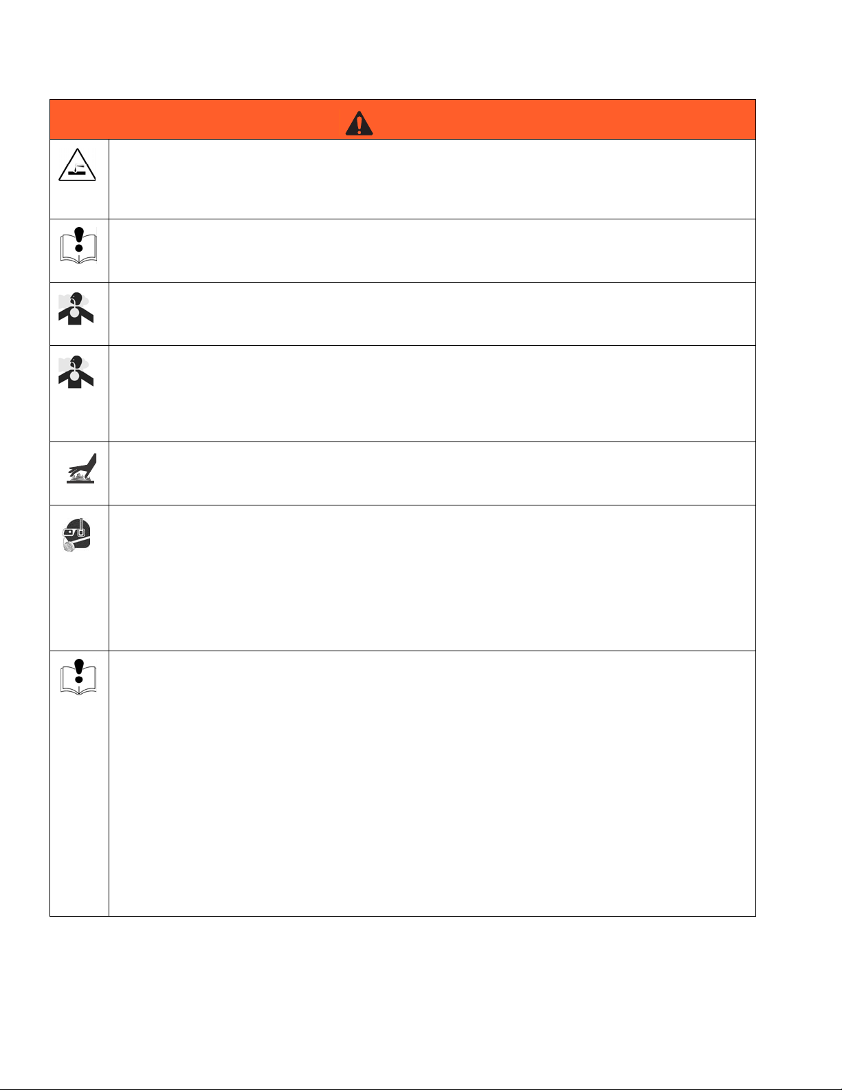
PRESSURIZED ALUMINUM PARTS HAZARD
Do not use 1,1,1-trichloroethane, methylene chloride, other halogenated hydrocarbon solvents or fluids
containing such solvents in pressurized aluminum equipment. Such use can cause serious chemical
reaction and equipment rupture, and result in death, serious injury, and property damage.
SUCTION HAZARD
Never place hands near the pump fluid inlet when pump is operating or pressurized. Powerful suction
could cause serious injury.
CARBON MONOXIDE HAZARD
Exhaust contains poisonous carbon monoxide, which is colorless and odorless. Breathing carbon monoxide can cause death. Do not operate in an enclosed area.
TOXIC FLUID OR FUMES HAZARD
Toxic fluids or fumes can cause serious injury or death if splashed in the eyes or on skin, inhaled, or
swallowed.
• Read MSDS’s to know the specific hazards of the fluids you are using.
• Store hazardous fluid in approved containers, and dispose of it according to applicable guidelines.
BURN HAZARD
Equipment surfaces and fluid that’s heated can become very hot during operation. To avoid severe
burns, do not touch hot fluid or equipment. Wait until equipment/fluid has cooled completely.
PERSONAL PROTECTIVE EQUIPMENT
You must wear appropriate protective equipment when operating, servicing, or when in the operating
area of the equipment to help protect you from serious injury, including eye injury, inhalation of toxic
fumes, burns, and hearing loss. This equipment includes but is not limited to:
• Protective eyewear
• Clothing and respirator as recommended by the fluid and solvent manufacturer
•Gloves
• Hearing protection
EQUIPMENT MISUSE HAZARD
Misuse can cause death or serious injury.
• Do not operate the unit when fatigued or under the influence of drugs or alcohol.
• Do not exceed the maximum working pressure or temperature rating of the lowest rated system
component. See Technical Data in all equipment manuals.
• Do not leave the work area while equipment is energized or under pressure. Turn off all equipment
and follow the Pressure Relief Procedure in this manual when equipment is not in use.
• Check equipment daily. Repair or replace worn or damaged parts immediately with genuine manufacturer’s replacement parts only.
• Do not alter or modify equipment.
• Use equipment only for its intended purpose. Call your distributor for information.
• Route hoses and cables away from traffic areas, sharp edges, moving parts, and hot surfaces.
• Do not kink or over bend hoses or use hoses to pull equipment.
• Keep children and animals away from work area.
• Comply with all applicable safety regulations.
4 313889B
Page 5
Component Identification - Sprayer
1
2
3
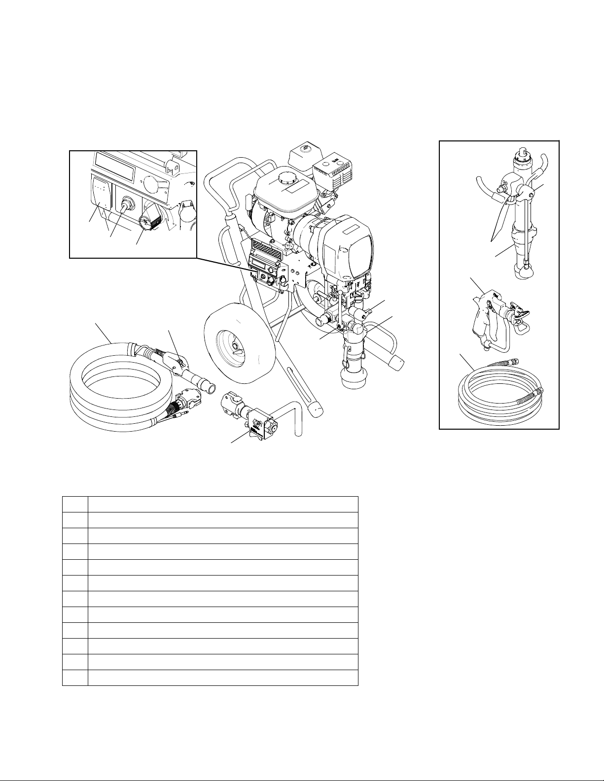
Component Identification - Sprayer
Top Coat Kit
8
9
10
8
4
1 ON/OFF Switch
2 Prime Switch (used with Base Coat Pump)
3 Pump Control
4 Heavy Texture Material Hose (used with Base Coat Pump)
5 Applicator Switch (used with Base Coat Pump--on Hose 5)
6 Applicator (Base Coat)
7 Pump (Base Coat)
8 Over Pressure Relief Valve
9 Pump (Top Coat)
10 Spray Gun (Top Coat)
11 Paint/Texture Material Hose (used with Top Coat Pump)
12 Prime/Drain Valve
5
12
6
7
11
ti14415a
313889B 5
Page 6
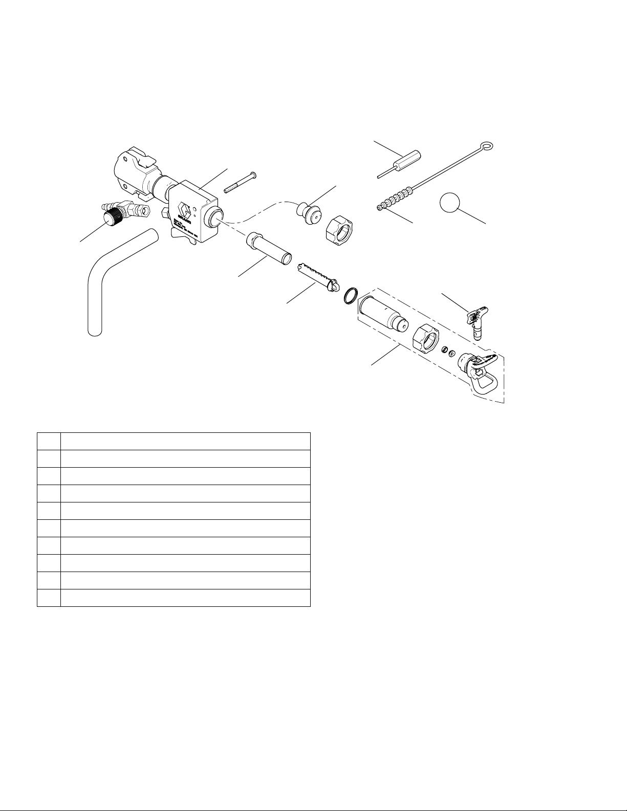
Component Identification - Base Coat Applicator
Component Identification - Base Coat Applicator
8
1
7
2
3
1 Applicator
2 Air Hose Adapter and Air Adjustment Valve
3 Airless Filter or Air Passage Plug
4 Filter Support
5 Airless Spray Assembly
6 Airless Spray Tip
9
6
4
5
10
ti14357a
7 Air nozzle, 4 mm, 6mm, 8mm, 10mm
8 Air Nozzle Cleaner
9 Cleaning Brush
10 Cleaning Ball
6 313889B
Page 7

Troubleshooting
Troubleshooting
Problem Cause Solution
E=XX is displayed Fault condition exists Determine fault correction from Digital Display Mes-
sages table, see manual 313888.
Engine will not start Engine switch is OFF Turn engine switch ON
Engine is out of gasoline Refill gas tank. Honda Engines Owner's Manual.
Engine oil level is low Try to start engine. Replenish oil, if necessary.
Honda Engines Owner's Manual.
Spark plug is disconnected or damaged Connect spark plug cable or replace spark plug
Cold engine Use choke
Fuel shutoff lever is OFF Move lever to ON position
Oil is seeping into combustion chamber Remove spark plug. Pull starter 3 to 4 times. Clean
or replace spark plug. Start engine. Keep sprayer
upright to avoid oil seepage
Engine operates, but displacement pump does not operate
Error code displayed Reference Pressure Control repair, page 18.
Applicator switch is OFF
(Base Coat Only)
Pump setting is OFF Turn pressure adjusting knob clockwise to increase
Tip or tip filter is clogged Clean tip or tip filter, see manual 313537/313603.
Displacement pump piston rod is stuck
due to dried paint or texture
Connecting rod is worn or damaged Replace connecting rod. Page 10.
Drive housing is worn or damaged Replace drive housing. Page 12.
Electrical power is not energizing clutch
field
Clutch is worn, damaged, or incorrectly
positioned
Pinion assembly is worn or damaged Repair or replace pinion assembly. Page 13.
Base Coat Pump: Applicator switch on
material hose and/or Prime Switch on
Pressure Control are damaged.
Top Coat Pum p: Pump is not correctly
aligned to pump sensor or sensor is
damaged.
Turn applicator switch ON
pressure.
Repair pump, see manual 310894 or page 22.
Check wiring connections. Page 24.
Reference Digital Display Messages, manual
313888.
Reference Wiring Diagram. Page 24.
With applicator switch ON and pressure turned to
MAXIMUM, use a test light to check for power
between clutch test points on control board.
Remove clutch wires from control board and mea-
sure resistance across clutch coil. At 70° F (21° C),
the resistance must be between 1.2 +0.2Ω; if not,
replace pinion housing.
Have pressure control checked by authorized Graco
dealer
Adjust or replace clutch. Page 17.
See page 22.
Rotate pump to align transducer port toward back of
sprayer. Replace damaged pump sensor.
313889B 7
Page 8

Troubleshooting
Problem Cause Solution
Pump output is low
(Base Coat Pump see pages
22.
Top Coat Pump see manual
310894)
Excessive paint leakage into
throat packing nut
Fluid is spitting from gun Air in pump or hose Check and tighten all fluid connections. Reprime
Pump is difficult to prime Air in pump or inlet tube Check and tighten all fluid connections.
Strainer (82) is clogged Clean strainer.
Piston ball is not seating Service piston ball.
Piston packings are worn or damaged Replace packings.
O-ring in pump is worn or damaged Replace o-ring.
Intake valve ball is not seating properly Clean intake valve.
Intake valve is packed with material Clean intake valve.
Engine speed is too low Increase throttle setting.
Clutch is worn or damaged Adjust or replace clutch. Page 17.
Pressure setting is too low Increase pressure.
Tip filter or tip is clogged or dirty Clean filter.
Large pressure drop in hose with heavy
materials
Throat packing nut is loose Remove throat packing nut spacer. Tighten throat
Throat packings are worn or damaged Replace packings.
Displacement rod is worn or damaged Replace rod.
Tip is partially clogged Clear tip.
Fluid supply is low or empty Refill fluid supply. Prime pump. Check fluid supply
Use larger diameter hose and/or reduce overall
length of hose.
packing nut just enough to stop leakage.
pump.
often to prevent running pump dry.
Reduce engine speed and cycle pump as slowly as
possible during priming.
Intake valve is leaking or contaminated Clean intake valve. Be sure ball seat is not nicked or
worn and that ball seats well. Reassemble valve.
Pump packings are worn Replace pump packings.
Paint is too thick Thin the paint according to the supplier's recommen-
dations
Engine speed is too high Decrease throttle setting before priming pump.
Prime/Drain valve is plugged Material hardened in valve Operate drain valve at least once per hour when
spraying.
Flush valve more thoroughly when cleaning sprayer.
Aggregate packed up in valve Valve is opened too slowly and/or aggregate is too
large.
Over pressure relief valve
actuates
Clutch squeaks each time clutch
engages
High engine speed at no load Misadjusted throttle setting Reset throttle to 3300 engine rpm at no load.
No display, sprayer operates Display damaged or has bad connec-
Clutch is worn out or damaged. Pressure transducer or control board are
damaged.
Valve is damaged or worn. Clean out debris and replace valve.
Clutch surfaces are not matched to
each other when new and may cause
noise
Worn engine governor Replace or service engine governor
tion
Check and replace worn or damaged component.
Clutch surfaces need to wear into each other. Noise
will dissipate after a day of run time.
Check connections. Replace display.
8 313889B
Page 9
Pressure Relief Procedure
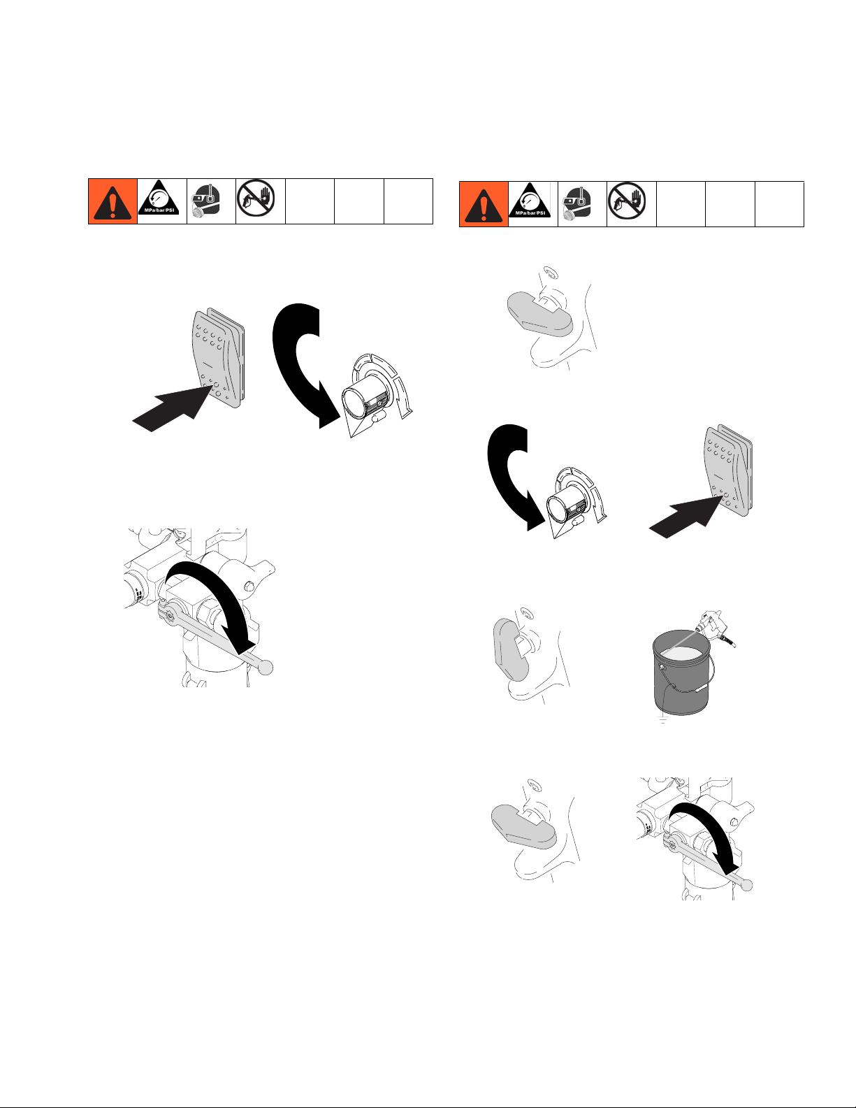
Pressure Relief Procedure
Applicator (Base Coat Pump)
1. Turn engine OFF.
2. Turn on/off switch OFF and turn pressure control
knob fully counterclockwise.
ti6208b
ti13050a
3. Turn prime/drain valve down to DRAIN position.
Fluid from drain valve can splash in eyes or skin and
cause serious injury. Keep hands clear of pressure
relief valve and always wear safety glasses.
Spray Gun (Top Coat Pump)
1. Lock gun trigger safety and turn engine OFF.
ti13131a
2. Turn on/off switch to OFF and turn pressure control
knob fully counterclockwise.
ti13050a
ti10796b
3. Unlock trigger safety. Hold metal part of gun firmly
to side of grounded metal pail and trigger gun to
relieve pressure.
ti14632a
NOTE: If you suspect spray tip nozzle or hose is completely clogged or that pressure has not been fully
relieved after following the previous steps, cover the
connection at end of hose with a heavy rag and very
slowly loosen connection.
ti13130a
ti13128a
4. Lock gun trigger safety. Open pressure prime/drain
valve. Leave valve open until ready to spray again.
ti13131a
ti14632a
NOTE: If you suspect that the spray tip nozzle or hose is
completely clogged, or that pressure has not been fully
relieved after following the previous steps, VERY
SLOWLY loosen the tip guard retaining nut or hose end
coupling to relieve pressure gradually, then loosen completely. Then clear tip nozzle or hose.
313889B 9
Page 10

Repair
Repair
Bearing Housing and Connecting Rod
Removal
Relieve Pressure, page 9.
1. Remove Pump, page 22.
Remove four screws (45) and front cover (44).
45
ti13706a
44
2. Remove four screws (64) and washers (63) from
ProConnect bearing housing (40).
63
64
3. Pull connecting rod (43) and lightly tap lower rear of
bearing housing with plastic mallet to loosen from
drive housing (33). Pull bearing housing and connecting rod assembly off drive housing.
33
B
43
ti13713a
4. Inspect crank (B) and connecting rod (43) for excessive wear and replace parts as needed.
40
10 313889B
ti13707a
Page 11

Installation
Repair
1. Evenly lubricate inside of bronze bearing (C) in
bearing housing (40) with high-quality motor oil. Liberally pack top roller bearing (E), lower bearing (D)
inside connecting rod (43) with bearing grease.
E
D
C
43
40
ti13714a
2. Assemble connecting rod (43) to bearing housing
(40). Rotate connecting rod to lowest position.
3. Clean mating surfaces of bearing and drive housings.
33
B
43
4. Align connecting rod with crank (B) and carefully
align locating pins (F) in drive housing (33) with
holes in bearing housing (40). Push bearing housing
onto drive housing or tap into place with plastic mallet.
NOTICE
Do not use bearing housing screws (41) to align or seat
bearing housing with drive housing. Align these parts
with locating pins to avoid premature bearing wear.
5. Install screws (41) and washers (42) in bearing
housing. Torque evenly to 40 ft-lb (54 N•m).
6. Install Pump, page 22.
F
ti13715a
313889B 11
Page 12

Repair
Drive Housing
Removal
Relieve Pressure, page 9.
1. Remove Bearing Housing, page 10.
NOTICE
Thrust washers may stick to grease inside of drive
housing. Do not lose or misplace.
2. Remove six screws (38).
3. Lightly tap around drive housing (33) to loosen drive
housing. Pull drive housing straight off pinion housing. Be prepared to support combination gear (32)
which may also come out.
29
33
38
32
ti13712a
Installation
2. Ensure thrust washers (30, 31) are on combination
gear (32) and washers (33a, 33b) are on crankshaft
of drive housing (33).
30
30
31
32
ti6252a
3. Clean mating surfaces of pinion and drive housing.
4. Align gears and push new drive housing straight
onto pinion housing (29) and locating pins (B).
33a
33b
29
ti13840a
5. Install six screws (38). Torque evenly to 200 ± 10
in-lb (22.6 ± 1.1 N•m).
1. Apply all grease supplied with replacement gear
cluster to gear teeth and mating surfaces.
38
ti13712a
6. Install housing (40) and (43), see page 10.
7. Install Pump, page 22.
NOTICE
DO NOT use drive housing screws to align or seat
drive housing with pinion housing. Align these parts
with locating pins to avoid premature bearing wear.
12 313889B
Page 13

Pinion Assembly / Clutch Armature / Clamp
Repair
Pinion Assembly / Clutch Armature
Removal
If pinion assembly (29) is not removed from clutch housing (19), perform steps 1 through 3. Otherwise, start at
step 4.
Pinion Assembly
1. Remove drive housing, page 12.
ti13712a
2. Disconnect clutch cable connectors from inside of
pressure control:
c. Remove strain reliefs (70b).
ti13710a
3. Remove four screws (36), washers (37), and pinion
assembly (29).
36
37
19
ti13711a
4. Place pinion assembly (29) on bench with rotor side
up.
24
E
28
ti13356a
a. Remove two screws (71) and swing down cover
(70a).
71
70a
ti13709a
b. Disconnect engine leads from board to engine.
ti13703a
29
ti5481a
5. Remove four screws (28) and lock washers (24).
Install two screws in threaded holes (E) in rotor.
Alternately tighten screws until rotor comes off.
ti13215a
6. Remove retaining ring (29b).
29b
29a
ti5482a
7. Turn pinion assembly over and tap pinion shaft
(29a) out with plastic mallet.
313889B 13
Page 14

Repair
Clutch Armature
8. Use an impact wrench or wedge something
between clutch armature (25) and clutch housing to
hold engine shaft during removal.
25
24
23
ti5483a
9. Remove four screws (23) and lock washers (24).
10. Remove armature (25).
Installation
Clutch Armature
1. Lay two stacks of two dimes (or 1.4mm coins) on a
smooth bench surface.
26
Clamp Removal
Gasoline can spill and cause a fire or explosion if engine
is tipped on its side.
1. Remove Engine, page 17, and drain gasoline from
tank according to Honda manual.
2. Tip engine on side so gas tank is down and air
cleaner is up.
ti13250a
3. Use 3/16 in. hex key wrench to loosen two screws
(23) on clamp (22).
22
ti6321a
2. Lay armature (25) on two stacks of coins.
3. Press center of hub (26) down to bench surface.
25
ti6199b
4. Push screwdriver into slot in clamp (22) and remove
clamp.
14 313889B
Page 15

Clamp Installation
Repair
1. Install engine shaft key (18).
18
2. Tap clamp (22) onto engine shaft (A). Maintain
dimension of 2.612 ± .010 in. (66.34 ± .25mm).
Chamfer must face engine.
2.612 in.
(66.34 mm)
ti13216a
6. Check o-ring (29d) and replace if missing or damaged.
29d
ti13213a
7. Tap pinion shaft (29a) in with plastic mallet.
29a
ti13210a
8. Install retaining ring (29b) with beveled side facing
up.
3. Check dimension: Place rigid, straight steel bar (B)
across face of clutch housing (19). Use accurate
measuring device to measure distance between bar
and face of clamp. Adjust clamp as necessary.
Torque two screws (23) to 125 ± 10 in-lb (14 ± 1.1
N•m).
4. Install armature (25) on engine drive shaft.
25
24
23
ti5483a
5. Install four screws (23) and lock washers (24).
Torque to 125 ± 10 in-lb (14 ± 1.1 N•m).
29b
ti13212a
313889B 15
Page 16

Repair
9. Place pinion assembly on bench with rotor side up.
10. Apply thread sealant to screws. Install four screws
(28) and lock washers (24). Alternately torque
screws to 125 ± 10 in-lb (14 ± 1.1 N•m) until rotor is
secure. Use threaded holes to hold rotor.
28
24
ti5481a
11. Install pinion assembly (29) with four screws (36)
and washers (37).
12. Connect clutch cable connectors to inside of pressure control.
ti13356a
ti13217a
16 313889B
Page 17

Clutch Housing
Repair
Removal
1. Remove four screws (20) and lock washers (21)
which hold clutch housing (19) to engine.
19
21
20
ti5486a
D
35
2. Remove screw (35) from under mounting plate (D).
3. Pull off clutch housing (19).
Installation
1. Push on clutch housing (19).
2. Install four capscrews (20) and lock washers (21)
and secure clutch housing (19) to engine. Torque to
200 in-lb (22.6 N•m).
19
21
20
2. Disconnect all necessary wiring.
ti13703a
3. Remove two locknuts (17) and screws (16) from
base of engine.
16
ti13716a
17
4. Lift engine carefully and place on work bench.
Installation
1. Lift engine carefully and place on sprayer cart.
2. Install two screws (16) in base of engine and secure
with locknuts (17). Torque to 26 ft-lb (22.6 N•m).
ti5486a
16
D
35
ti13716a
3. Install screw (35) from beneath mounting plate (D).
Torque to 26 ft-lb (35.2 N•m).
17
3. Connect all necessary wiring.
Engine
Removal
NOTE: All service to the engine must be
performed by an authorized Honda dealer.
1. Remove Pinion Assembly/Clutch Arma-
ture/Clamp and Clutch Housing.
313889B 17
4. Install Pinion Assembly/Clutch Armature/Clamp
and Clutch Housing.
ti13703a
Page 18

Repair
Pressure Control
Pump On/Off Switch
Removal
1. Remove two screws (71) and swing down cover
(70a).
71
71
70a
ti13709a
2. Disconnect pump ON/OFF switch (70j) connector
from control board.
Installation
1. Install new ON/OFF switch (70j) so tabs of switch
snap into place on inside of cover. Align new
ON/OFF switch with electrical tabs at bottom.
70j
2. Connect pump ON/OFF switch connector to control
board.
ti13248a
70j
ti13245a
3. Press in on two retaining tabs on each side of pump
ON/OFF switch (70j) and remove switch from cover.
70j
ti13248a
70j
ti13245a
3. Swing cover (70a) up and secure with two screws
(71).
71
71
70a
ti13709a
18 313889B
Page 19

Control Board
Repair
Removal
1. Remove two screws (71) and swing cover (70a)
down.
71
71
70a
ti13709a
2. Squeeze strain relief bushings (70b) with pliers and
remove.
70b
Installation
1. Install control board (70c) with four screws (70d).
70c
70d
ti13719a
2. Connect engine wires to control board (70c).
3. Connect all leads at control board (70c).
See Wiring Diagram, page 24.
4. Install new strain relief bushings (70b).
70b
ti13710a
3. Disconnect all leads at control board (70c).
See Wiring Diagram, page 24.
4. Remove four screws (70d) and control board (70c).
70c
70d
ti13719a
ti13710a
5. Swing cover (70a) up and secure with two screws
(71).
70a
71
ti13717a
313889B 19
Page 20

Repair
Pressure Control Transducer
Removal
1. Remove two screws (71) and swing cover (70a)
down.
71
71
70a
ti13709a
2. Disconnect transducer lead (158) from control board
(70c).
70c
Installation
1. Install o-ring (158b) and pressure control transducer
(158) in manifold (72). Tighten securely.
158b
158
ti13800a
2. Place end of transducer in slot of mount (183) and
secure with cover (184) and screws (182). Route
transducer cable through control box and secure
with strain relief (70b).
70b
ti13801a
3. Connect transducer lead (158) to control board
(70c).
158
ti13253a
3. Remove strain relief (70b) and pull transducer cable
from the control box. Remove screws (182) and
cover (184) to detach transducer from cart frame.
70b
ti13801a
4. Remove pressure control transducer (158) and
o-ring (158b) from manifold.
158b
158
ti13800a
70c
ti13253a
158
4. Swing cover (70a) up and secure with two screws
(71).
70a
ti13717a
71
20 313889B
Page 21

Pump Control
Repair
Removal
1. Remove two screws (71) and swing cover (70a)
down.
71
71
70a
ti13709a
2. Disconnect pump control (70p) lead from control
board (70c).
Installation
1. Install shaft spacer (70n) on pump control (70p).
2. Install pump control, shaft nut, lock washer, and
pump control knob (70k).
70p
70n
70k
a. Turn pump control shaft clockwise to internal
stop. Assemble pump control knob to strike pin
on cover (70a).
70k
ti14417a
ti13251a
70p
3. Loosen set screws on pump control knob (70k) and
remove knob, shaft nut, lock washer and pump control (70p).
70k
ti13207a
4. Remove shaft spacer (70n) from pump control.
70n
ti14417a
ti13338a
b. After adjustment of step a, tighten both set
screws in knob 1/4 to 3/8 turn after contact with
shaft.
3. Connect pump control lead to control board (70c).
ti13251a
70p
4. Swing cover (70a) up and secure with two screws
(71).
70a
ti13717a
71
313889B 21
Page 22

Repair
Displacement Pump
Removal
1. Flush pump, page 22.
2. Stop pump with piston rod in its lowest position.
3. Perform Pressure Relief procedure, page 9.
4. Top Coat Pump: Separate drain hose from sprayer.
ti11420a
5. Disconnect transducer from pump manifold.
c. Place u-bolt on pump door outer edge.
d. If pump door is stuck, do steps e, f, and 8. Oth-
erwise, go to step 9.
e. Twist latch u-bolt back from pump door outer
edge.
ti6374a
f. Place u-bolt on pump door protrusion.
ti6375a
8. Ratchet pump door forward.
ti13704a
6. Raise latch lock and push latch open.
ti6369b
9. Open pump door.
ti6370b
ti6373a
ti13730a
7. Ratchet open pump door.
10. Pull out pump pin and place in pin holder.
ti6373a
a. Ratchet pump door forward.
ti13726a
b. Twist latch u-bolt out of pump door recess.
22 313889B
Page 23

Installation
Repair
1. Adjust piston rod to proper length:
Adjust piston rod with pin holder to pull out piston
rod. Tap piston rod on hard surface to push in piston
rod.
ti5492a
2. Slide pump into connecting rod. Push pump collar
flush with bearing housing ledge to be able to close
pump door.
5. Rotate pump until transducer port is aligned directly
to back of sprayer. Connect transducer and hand
tighten securely.
NOTE: Clean out ALL media and debris from transducer and transducer port before connecting transducer.
ti13729a
6. Tighten latch and rotate latch lock into locked position.
ti6312a
ti6204a
ti6325a
3. Push pump pin until it is fully retained.
NOTE: Pin will snap into position.
ti13727a
ti6378a
4. Close pump door and rotate latch into position. Do
not tighten latch.
ti6313a
ti13728a
7. Top Coat Pump: Attach drain hose to sprayer.
ti7330a
8. Fill pump with Graco TSL until fluid flows onto top of
seal.
ti5493a
313889B 23
Page 24

Wiring Diagram
Wiring Diagram
D
C
B
E
A
H
LED
D12
J2
J1
J5J4J3
J10
G
J9
ti13556a
N
F
J
M
K
A To Engine
B To Ground
C Clutch Test Points
D Pinion
EDrive
F On/Off Switch
24 313889B
G Control Board
H Pump Sensor
J Pump/Prime Switch
K Display Board
M Pump Control
N Transducer
Page 25

Technical Data
Technical Data
Honda GX 200 Engine:
ANSI Power Rating @ 3600 rpm 6.5 Horsepower (4.8 kW)
Maximum Working Pressure:
Base Coat Pump 1000 psi (69 bar, 6.9 MPa)
Top Coat Pump 3300 psi (228 bar, 22.8 MPa)
Noise Level:
Sound Power 105 dBa per ISO 3744
Sound Pressure 96 dBa measured at 3.1 ft (1 m)
Maximum Delivery Rating:
Base Coat Pump 3.0 gpm (11.36 liter/min)
Top Coat Pump 2.20 gpm (8.33 liter/min)
Maximum Tip Nozzle Size:
Base Coat Pump 1 applicator with .071 in. tip or 10 mm Nozzle
Top Coat Pump 1 gun with 0.048 in. tip nozzle
2 guns with 0.035 in. tip nozzle
3 guns with 0.027 in. tip nozzle
4 guns with 0.023 in. tip nozzle
Inlet Paint Strainer:
Base Coat Pump 2 in. npsm, #5 mesh sst
Top Coat Pump 1 in. npsm, #8 mesh sst
Pump Inlet Size:
Base Coat Pump 2 in. QD Camlock male coupler
Top Coat Pump 1 in. - 11.5 npsm
Fluid Outlet Size:
Base Coat Pump 1 in. QD Camlock male coupler
Top Coat Pump 3/8 npsm
Wetted Parts: zinc-plated carbon steel, PTFE, nylon, polyurethane, UHMW, polyethyl-
ene, fluoroelastomer, acetal, leather, aluminum, tungsten carbide,
nickel- and zinc-plated carbon steel, stainless steel, chrome plating
Dimensions
Part Weight lb (kg) Height in. (cm) Width in. (cm) Length in. (cm)
HTX 2030 Sprayer 155 (70.5) 34.25 (87.0) 24.5 (62.2) 33.0 (83.8)
3/4 in. Hose 29 (13.2) — — —
Applicator/Swivel 3 (1.3) — — —
313889B 25
Page 26

Notes
Notes
26 313889B
Page 27

Notes
313889B 27
Page 28

Graco Standard Warranty
Graco Standard Warranty
Graco warrants all equipment referenced in this document which is manufactured by Graco and bearing its name to be free from defects in
material and workmanship on the date of sale to the original purchaser for use. With the exception of any special, extended, or limited warranty
published by Graco, Graco will, for a period of twelve months from the date of sale, repair or replace any part of the equipment determined by
Graco to be defective. This warranty applies only when the equipment is installed, operated and maintained in accordance with Graco’s written
recommendations.
This warranty does not cover, and Graco shall not be liable for general wear and tear, or any malfunction, damage or wear caused by faulty
installation, misapplication, abrasion, corrosion, inadequate or improper maintenance, negligence, accident, tampering, or substitution of
non-Graco component parts. Nor shall Graco be liable for malfunction, damage or wear caused by the incompatibility of Graco equipment with
structures, accessories, equipment or materials not supplied by Graco, or the improper design, manufacture, installation, operation or
maintenance of structures, accessories, equipment or materials not supplied by Graco.
This warranty is conditioned upon the prepaid return of the equipment claimed to be defective to an authorized Graco distributor for verification of
the claimed defect. If the claimed defect is verified, Graco will repair or replace free of charge any defective parts. The equipment will be returned
to the original purchaser transportation prepaid. If inspection of the equipment does not disclose any defect in material or workmanship, repairs will
be made at a reasonable charge, which charges may include the costs of parts, labor, and transportation.
THIS WARRANTY IS EXCLUSIVE, AND IS IN LIEU OF ANY OTHER WARRANTIES, EXPRESS OR IMPLIED, INCLUDING BUT NOT LIMITED
TO WARRANTY OF MERCHANTABILITY OR WARRANTY OF FITNESS FOR A PARTICULAR PURPOSE.
Graco’s sole obligation and buyer’s sole remedy for any breach of warranty shall be as set forth above. The buyer agrees that no other remedy
(including, but not limited to, incidental or consequential damages for lost profits, lost sales, injury to person or property, or any other incidental or
consequential loss) shall be available. Any action for breach of warranty must be brought within two (2) years of the date of sale.
GRACO MAKES NO WARRANTY, AND DISCLAIMS ALL IMPLIED WARRANTIES OF MERCHANTABILITY AND FITNESS FOR A
PARTICULAR PURPOSE, IN CONNECTION WITH ACCESSORIES, EQUIPMENT, MATERIALS OR COMPONENTS SOLD BUT NOT
MANUFACTURED BY GRACO. These items sold, but not manufactured by Graco (such as electric motors, switches, hose, etc.), are subject to
the warranty, if any, of their manufacturer. Graco will provide purchaser with reasonable assistance in making any claim for breach of these
warranties.
In no event will Graco be liable for indirect, incidental, special or consequential damages resulting from Graco supplying equipment hereunder, or
the furnishing, performance, or use of any products or other goods sold hereto, whether due to a breach of contract, breach of warranty, the
negligence of Graco, or otherwise.
FOR GRACO CANADA CUSTOMERS
The Parties acknowledge that they have required that the present document, as well as all documents, notices and legal proceedings entered into,
given or instituted pursuant hereto or relating directly or indirectly hereto, be drawn up in English. Les parties reconnaissent avoir convenu que la
rédaction du présente document sera en Anglais, ainsi que tous documents, avis et procédures judiciaires exécutés, donnés ou intentés, à la suite
de ou en rapport, directement ou indirectement, avec les procédures concernées.
TO PLACE AN ORDER, contact your Graco distributor, or call 1-800-690-2894 to identify the nearest distributor.
All written and visual data contained in this document reflects the latest product information available at the time of publication.
Graco reserves the right to make changes at any time without notice.
This manual contains: English.
mm 313889
Graco Headquarters: Minneapolis
International Offices: Belgium, Korea, China, Japan
GRACO INC. P.O. BOX 1441 MINNEAPOLIS, MN 55440-1441
http://www.graco.com
28 313889B
 Loading...