

Page 1
Operation
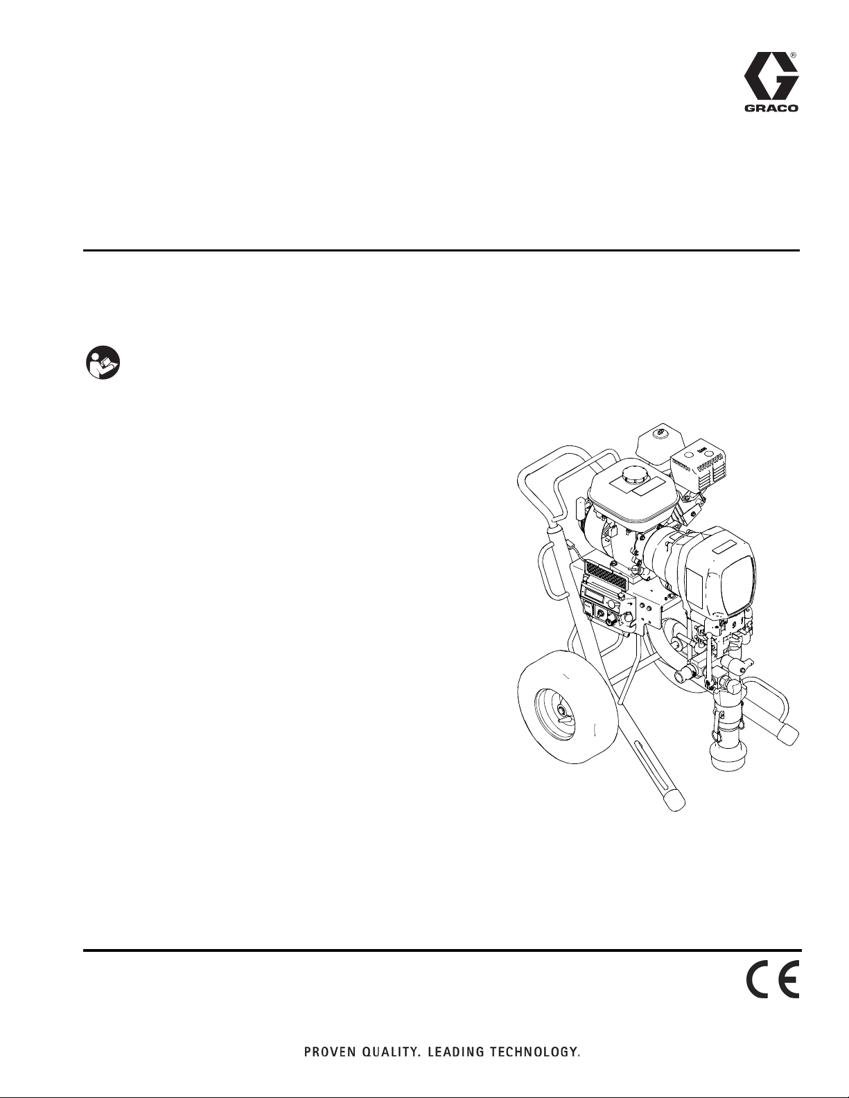
HTX 2030
-For Portable Airless and Air-Assisted Spraying of Water-Based Architectural Coatings with Base Coat Pump-
-For Airless Spraying Architectural Coatings and Paints with Top Coat Pump-
IMPORTANT SAFETY INSTRUCTIONS
Read all warnings and instructions in this
manual. Save these instructions.
Model Number: 257369 (HTX2030 FreeFlo Inline Gun)
Model Number: 278675 (HTX2030 AirSpray Trigger Gun)
Maximum Working Pressure:
Base Coat Pump: 1000 psi (69 bar, 6.9 MPa)
Top Coat Pump: 3300 psi (228 bar, 22.8 MPa)
Related Manuals
313891 - Operation (French)
313893 - Operation (Spanish)
313889 - Repair (English)
313892 - Repair (French)
313893 - Repair (Spanish)
313890 - Parts
313895 - HTX 2030 Flex Head and Pole Spray Applicator (English)
313896 - HTX 2030 Flex Head and Pole Spray Applicator (French)
313897 - HTX 2030 Flex Head and Pole Spray Applicator (Spanish)
310894 - Displacement Pump (Top Coat)
308491 - Airless Heavy Duty Texture Gun
313537 - HTX 2030 FreeFlo Inline Gun (English)
313603 - HTX 2030 FreeFlo Inline Gun (Chinese)
313908 - HTX 2030 FreeFlo Inline Gun (French)
313911 - HTX 2030 FreeFlo Inline Gun (Spanish)
332160 - HTX2030 AirSpray Trigger Gun (English)
332227 - HTX2030 AirSpray Trigger Gun (French)
332228 - HTX2030 AirSpray Trigger Gun (Spanish)
332229 - HTX2030 AirSpray Trigger Gun (Chinese)
313888E
EN
ti13632a
Page 2

Contents
Contents
Contents . . . . . . . . . . . . . . . . . . . . . . . . . . . . . . . . . . 2
Warnings . . . . . . . . . . . . . . . . . . . . . . . . . . . . . . . . . 3
Product Overview . . . . . . . . . . . . . . . . . . . . . . . . . . 5
HTX 2030 with Base Coat Pump (257369) . . . . . 5
Top Coat Pump (Kit 24B140) . . . . . . . . . . . . . . . 6
Component Identification - Sprayer . . . . . . . . . . . 7
Component Identification - Base Coat Applicator 8
Component Identification - HTX2030 Air Spray
Trigger Gun . . . . . . . . . . . . . . . . . . . . . . . . . . . . 9
Grounding . . . . . . . . . . . . . . . . . . . . . . . . . . . . . . . 10
Pressure Relief Procedure . . . . . . . . . . . . . . . . . . 10
Applicator (Base Coat Pump) . . . . . . . . . . . . . . 10
Spray Gun (Top Coat Pump) . . . . . . . . . . . . . . 11
Start Engine . . . . . . . . . . . . . . . . . . . . . . . . . . . . . . 12
Setup . . . . . . . . . . . . . . . . . . . . . . . . . . . . . . . . . . . . 13
Material and Sprayer Preparation . . . . . . . . . . . 13
Prime Pump . . . . . . . . . . . . . . . . . . . . . . . . . . . 13
Spray With Airless Tip . . . . . . . . . . . . . . . . . . . . 14
Spray Without Air - Clear Clog . . . . . . . . . . . . . 15
Air Assisted Spray
(Base Coat Applicator) . . . . . . . . . . . . . . . . 15
Air Assisted Spray
(Air Spray Trigger Gun) . . . . . . . . . . . . . . . 16
Spray Gun (Top Coat Pump) . . . . . . . . . . . . . . 17
Cleanup . . . . . . . . . . . . . . . . . . . . . . . . . . . . . . . . . 18
Digital Tracking System (DTS) . . . . . . . . . . . . . . . 21
Main Menu . . . . . . . . . . . . . . . . . . . . . . . . . . . . 21
Secondary Menu - Stored Data Mode . . . . . . . 22
Digital Display Messages . . . . . . . . . . . . . . . . . . . 23
Maintenance . . . . . . . . . . . . . . . . . . . . . . . . . . . . . . 24
Technical Data . . . . . . . . . . . . . . . . . . . . . . . . . . . . 25
Dimensions . . . . . . . . . . . . . . . . . . . . . . . . . . . . 25
Notes . . . . . . . . . . . . . . . . . . . . . . . . . . . . . . . . . . . . 26
Notes . . . . . . . . . . . . . . . . . . . . . . . . . . . . . . . . . . . . 27
Graco Standard Warranty . . . . . . . . . . . . . . . . . . . 28
2 313888E
Page 3
Warnings
Warnings
The following warnings are for the setup, use, grounding, maintenance, and repair of this equipment. The exclamation point symbol alerts you to a general warning and the hazard symbols refer to procedure-specific risks. When
these symbols appear in the body of this manual or on warning labels, refer back to these Warnings. Product-specific
hazard symbols and warnings not covered in this section may appear throughout the body of this manual where
applicable.
WARNING
FIRE AND EXPLOSION HAZARD
Flammable fumes, such as solvent and paint fumes, in work area can ignite or explode. To help prevent fire
and explosion:
•
Use equipment only in well ventilated area.
•
Do not fill fuel tank while engine is running or hot; shut off engine and let it cool. Fuel is flammable and can
ignite or explode if spilled on hot surface.
•
Eliminate all ignition sources; such as pilot lights, cigarettes, portable electric lamps, and plastic drop
cloths (potential static arc).
•
Keep work area free of debris, including solvent, rags and gasoline.
•
Do not plug or unplug power cords, or turn power or light switches on or off when flammable fumes are
present.
•
Ground all equipment in the work area. See Grounding instructions.
•
Use only grounded hoses.
•
Hold gun firmly to side of grounded pail when triggering into pail. Do not use pail liners unless they are
antistatic or conductive.
•
Stop operation immediately if static sparking occurs or you feel a shock. Do not use equipment until you
identify and correct the problem.
•
Keep a working fire extinguisher in the work area.
SKIN INJECTION HAZARD (SPRAY GUN)
High-pressure fluid from gun, hose leaks, or ruptured components will pierce skin. This may look like just a
cut, but it is a serious injury that can result in amputation. Get immediate surgical treatment.
•
Do not point gun at anyone or at any part of the body.
•
Do not put your hand over the spray nozzle.
•
Do not stop or deflect leaks with your hand, body, glove, or rag.
•
Follow Pressure Relief Procedure in this manual when you stop spraying and before cleaning, checking,
or servicing equipment.
SKIN INJECTION HAZARD (APPLICATOR AND AIR SPRAY TRIGGER GUN)
High-pressure fluid from dispensing device, hose leaks, or ruptured components will pierce skin. This may
look like just a cut, but it is a serious injury that can result in amputation. Get immediate surgical treatment.
•
Do not point dispensing device at anyone or at any part of the body.
•
+
Do not put your hand over the fluid outlet.
•
Do not stop or deflect leaks with your hand, body, glove, or rag.
•
Follow the Pressure Relief Procedure when you stop dispensing and before cleaning, checking, or servicing equipment.
•
Tighten all fluid connections before operating the equipment.
•
Check hoses and couplings daily. Replace worn or damaged parts immediately.
MOVING PARTS HAZARD
Moving parts can pinch, cut or amputate fingers and other body parts.
•
Keep clear of moving parts.
•
Do not operate equipment with protective guards or covers removed.
•
Pressurized equipment can start without warning. Before checking, moving, or servicing equipment, follow the Pressure Relief Procedure and disconnect all power sources.
313888E 3
Page 4
Warnings
WARNING
RECOIL HAZARD
Gun may recoil when triggered. If you are not standing securely, you could fall and be seriously injured.
PRESSURIZED ALUMINUM PARTS HAZARD
Use of fluids that are incompatible with aluminum in pressurized equipment can cause serious chemical reaction
and equipment rupture. Failure to follow this warning can result in death, serious injury, or property damage.
•
Do not use 1,1,1-trichloroethane, methylene chloride, other halogenated hydrocarbon solvents or fluids containing such solvents.
•
Many other fluids may contain chemicals that can react with aluminum. Contact your material supplier for compatibility.
SUCTION HAZARD
Powerful suction could cause serious injury.
•
Never place hands near the pump fluid inlet when pump is operating or pressurized.
CARBON MONOXIDE HAZARD
Exhaust contains poisonous carbon monoxide, which is colorless and odorless. Breathing carbon monoxide can
cause death.
•
Do not operate in an enclosed area.
TOXIC FLUID OR FUMES HAZARD
Toxic fluids or fumes can cause serious injury or death if splashed in the eyes or on skin, inhaled, or swallowed.
•
Read MSDSs to know the specific hazards of the fluids you are using.
•
Store hazardous fluid in approved containers, and dispose of it according to applicable guidelines.
BURN HAZARD
Equipment surfaces and fluid that’s heated can become very hot during operation. To avoid severe burns:
•
Do not touch hot fluid or equipment.
PERSONAL PROTECTIVE EQUIPMENT
Wear appropriate protective equipment when in the work area to help prevent serious injury, including eye injury,
hearing loss, inhalation of toxic fumes, and burns. This protective equipment includes but is not limited to:
•
Protective eyewear, and hearing protection.
•
Respirators, protective clothing, and gloves as recommended by the fluid and solvent manufacturer.
EQUIPMENT MISUSE HAZARD
Misuse can cause death or serious injury.
•
Do not operate the unit when fatigued or under the influence of drugs or alcohol.
•
Do not exceed the maximum working pressure or temperature rating of the lowest rated system component.
See Technical Data in all equipment manuals.
•
Use fluids and solvents that are compatible with equipment wetted parts. See Technical Data in all equipment
manuals. Read fluid and solvent manufacturer’s warnings. For complete information about your material,
request MSDS from distributor or retailer.
•
Do not leave the work area while equipment is energized or under pressure.
•
Turn off all equipment and follow the Pressure Relief Procedure when equipment is not in use.
•
Check equipment daily. Repair or replace worn or damaged parts immediately with genuine manufacturer’s
replacement parts only.
•
Do not alter or modify equipment. Alterations or modifications may void agency approvals and create safety
hazards.
•
Make sure all equipment is rated and approved for the environment in which you are using it.
•
Use equipment only for its intended purpose. Call your distributor for information.
•
Route hoses and cables away from traffic areas, sharp edges, moving parts, and hot surfaces.
•
Do not kink or over bend hoses or use hoses to pull equipment.
•
Keep children and animals away from work area.
•
Comply with all applicable safety regulations.
4 313888E
Page 5
Product Overview
Product Overview
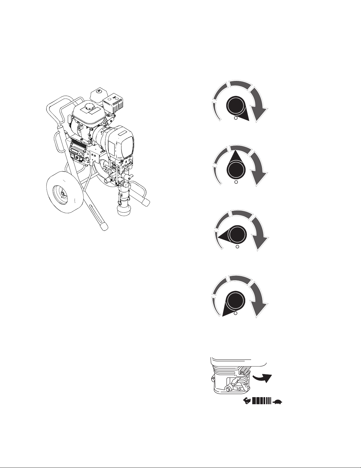
HTX 2030 with Base Coat Pump
(257369)
ti13632a
Flow rate is dependent on engine speed and the setting
of the pump control knob.
1. Flow 3 (fully clockwise) - allows the pump to run
continuously with minimal pulsation:
ti13756a
2. Flow 2 (near middle of the rotation) reduces flow
slightly by briefly interrupting pump:
ti13757a
3. Flow 1 (near counterclockwise end of pump control)
reduces flow more by interrupting pump longer:
The HTX 2030 Sprayer comes equipped with a Base
Coat Pump 24B321. Only water-based materials are to
be used with this configuration, such as:
• Smooth to heavily aggregated textures with silica
sand, perlite, vermiculite and polystyrene
• Smooth, medium, coarse and extra coarse textures
• Most materials with aggregates up to 2.5 mm (.100
in.) in longest dimension
When Base Coat Pump is Installed
Pump will only run when on/off switch is in ON position
AND:
• Pump control is rotated clockwise away from OFF
position, and either of the following switches are
also switched ON:
Prime Switch on pressure control box AND/OR
Applicator Switch near end of material hose
The pressure control will limit the sprayer to 1,000 psi
(69 bar), stopping the pump whenever pressure limit is
reached.
ti13758a
4. OFF (fully counterclockwise) - stops pump completely:
ti13755a
5. Adjust engine speed to control flow rate of sprayer.
Start with the slowest speed possible for maximum
spray control. Different spray tip nozzle sizes can
also be tried.
ti5251a
313888E 5
Page 6
Product Overview
Top Coat Pump (Kit 24B140)
ti13653a
The pump on the HTX 2030 Sprayer can also be
switched out with a Top Coat Kit 24B140 (purchased
separately). This pump is used for less viscous
materials such as:
• Oil-based coatings
• Enamels
• Latex
When Top Coat Pump is Installed
• Pump will only run when on/off switch is in ON posi-
tion and pump control is rotated clockwise away
from OFF position
• Pump control setting adjusts sprayer pressure
a. Rotating knob fully clockwise allows sprayer to
reach maximum working pressure of 3300 psi
(228 bar, 22.8 MPa)
b. Settings below maximum will lower system
pressure
• Pump will run whenever system pressure is below
the setting of the pump control
• Sprayer will not respond to Prime switch or Applicator switch when Top Coat pump is installed
• Block fillers
• Elastomerics
• Epoxies
• Drywall mud
• Other high-build materials
For instructions on installing the Top Coat Pump, see
manual 313889.
ti13653a
6 313888E
Page 7
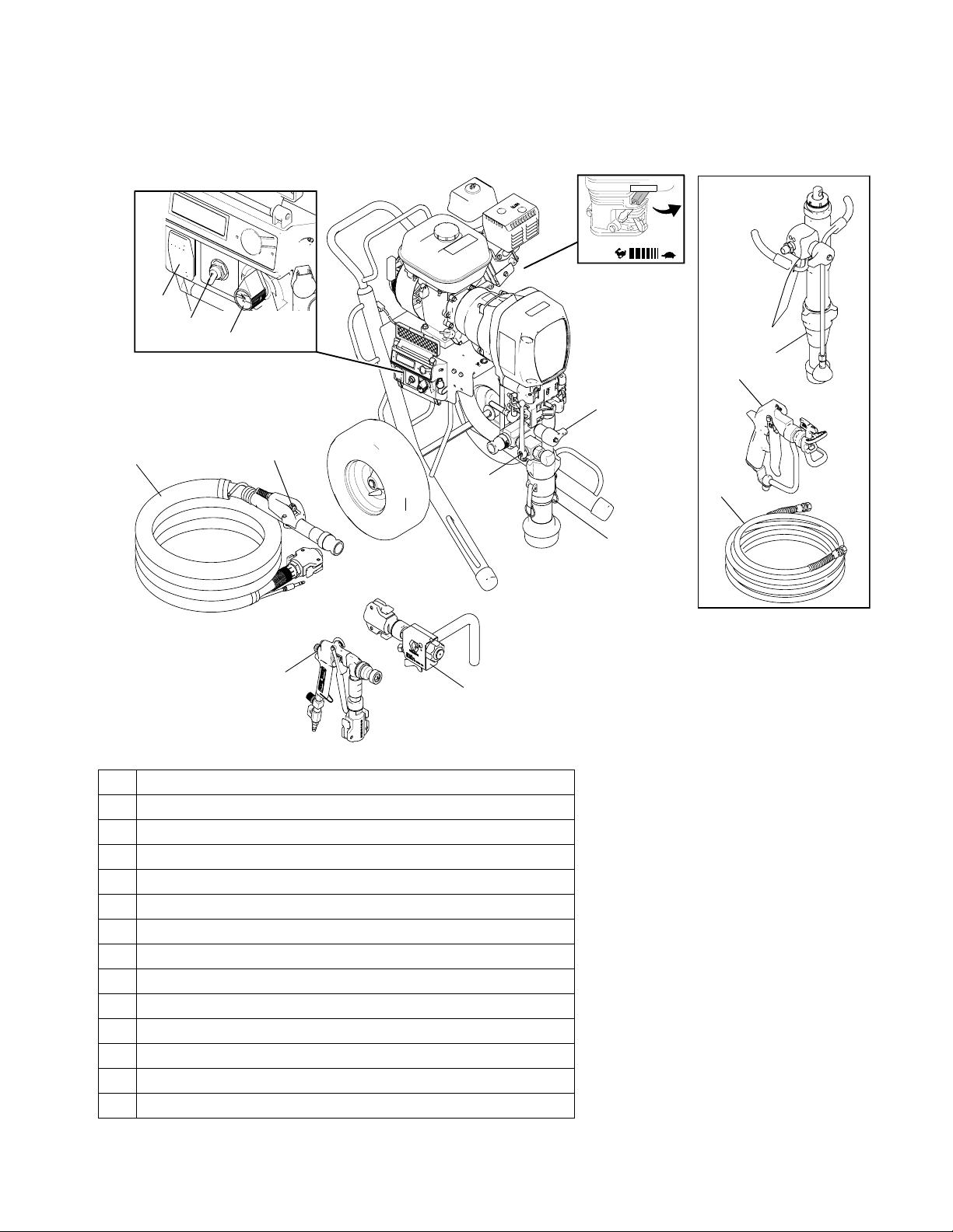
Component Identification - Sprayer
14
1
2
3
8
Component Identification - Sprayer
Top Coat Kit
9
10
4
1 ON/OFF Switch
2 Prime Switch (used with Base Coat Pump)
3 Pump Control Knob
4 Heavy Texture Material Hose (used with Base Coat Pump)
5 Applicator Switch (used with Base Coat Pump--on Hose)
6 Applicator (Base Coat) (Model 257369)
7 Pump (Base Coat)
8 Over Pressure Relief Valve
9 Pump (Top Coat)
10 Spray Gun (Top Coat)
11 Paint/Texture Material Hose (used with Top Coat Pump)
12 Prime/Drain Valve
13 Air Spray Gun (24R054)
14 Engine Throttle Lever/Material Flow
5
12
13
6
11
7
ti14415b
313888E 7
Page 8
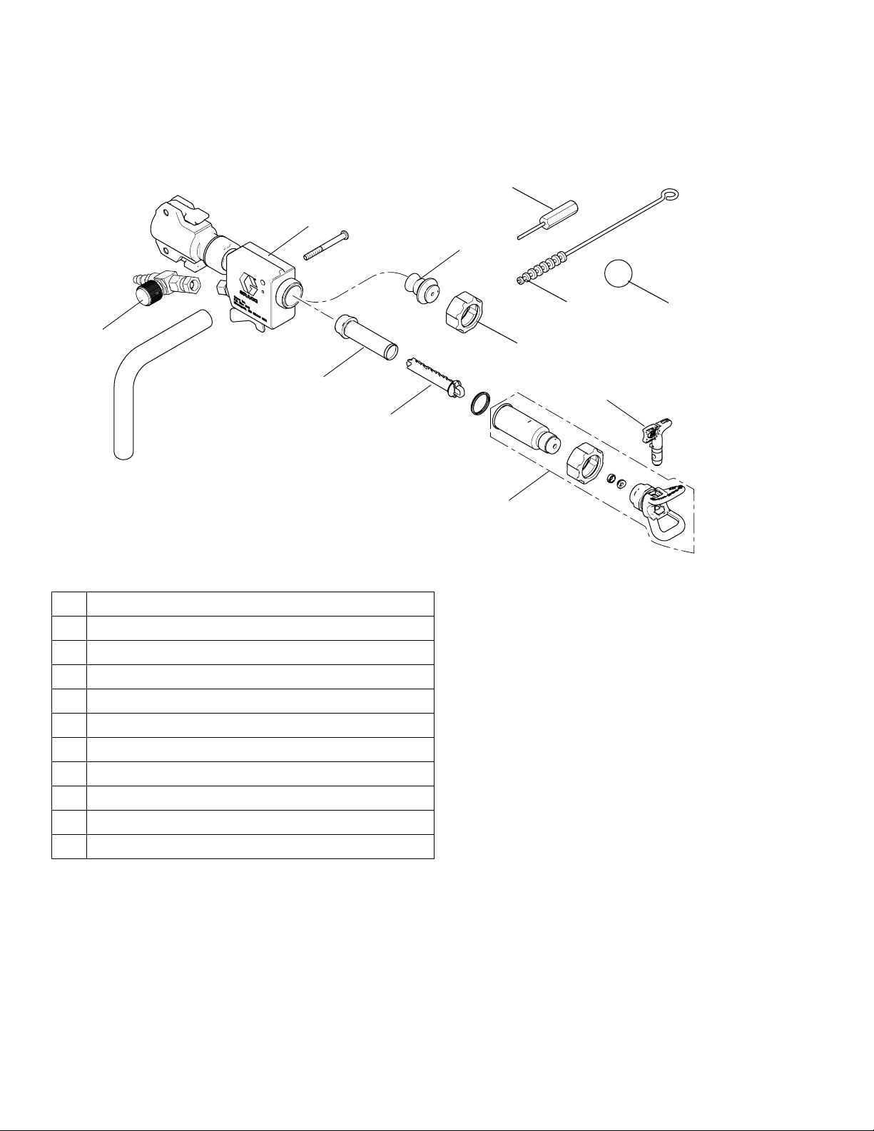
Component Identification - Base Coat Applicator
Component Identification - Base Coat Applicator
8
1
7
2
3
1 Applicator
2 Air Hose Adapter and Air Adjustment Valve
3 Airless Filter or Air Passage Plug
4 Filter Support
5 Airless Spray Assembly
6 Airless Spray Tip Nozzle
9
11
6
4
5
10
ti14357a
7 Air Nozzle (4 mm, 6mm, 8mm, 10mm)
8 Air Nozzle Cleaner
9 Cleaning Brush
10 Cleaning Ball
11 Retaining Nut
8 313888E
Page 9
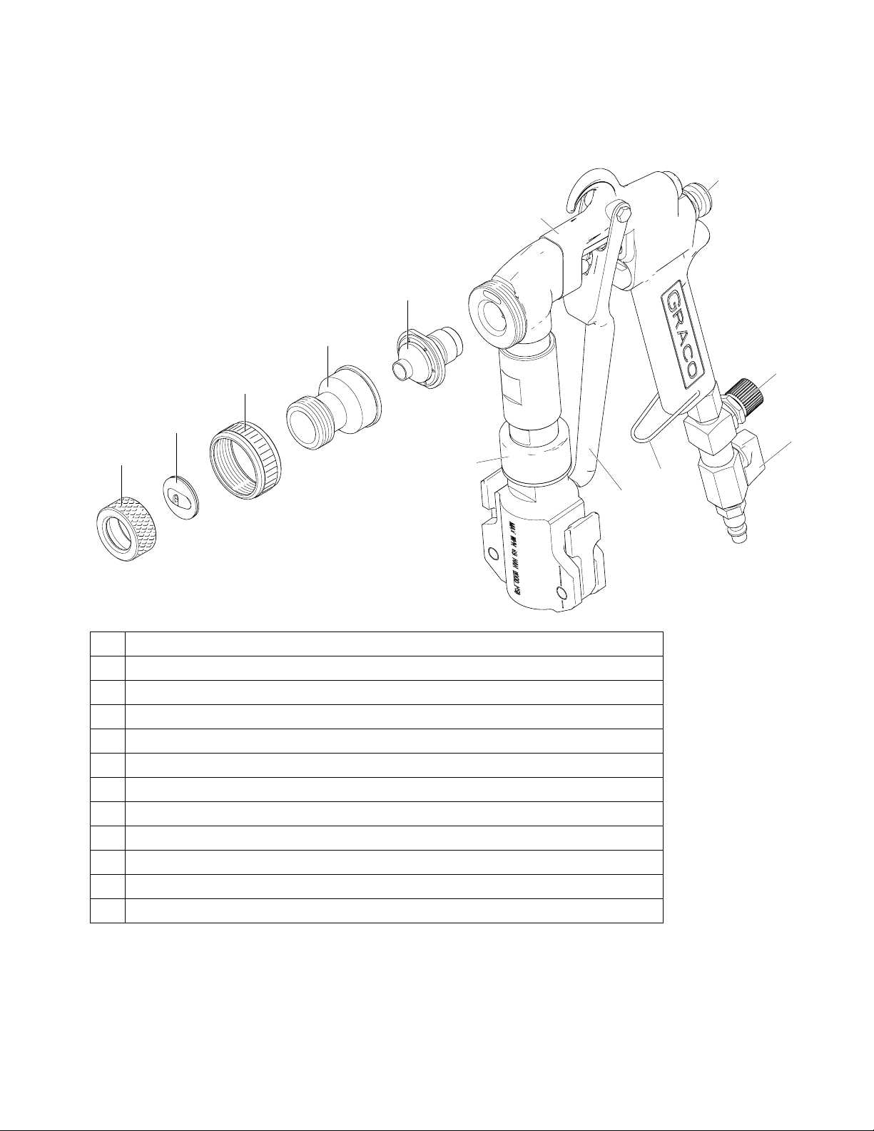
Component Identification - HTX2030 Air Spray Trigger Gun
Component Identification - HTX2030 Air Spray Trigger Gun
11
1
2
3
7
4
5
6
9
12
1 HTX2030 Air Spray Trigger Gun
2 Nozzle, Size #1, Size #2, Size #3
3 Adapter, Housing
4 Ring, Retaining Nozzles
5 Tip, Disc, Spray, 1/8 in. (3 mm), 1/4 in. (6.3 mm), 5/16 in. (8 mm), 3/8 in. (9.5 mm)
6 Ring, Retaining, Spray Discs
7 Air Adjustment Valve
8 Trigger, Latch On
9 HTX Swivel Assembly
10 Air, Control Ball Valve
10
8
ti21036a
11 Flow, Adjust Knob
12 Trigger
313888E 9
Page 10

Grounding
Grounding
The equipment must be grounded to reduce the risk of
static sparking. Static sparking can cause fumes to
ignite or explode. Grounding provides an escape wire
for the electric current.
Ground sprayer with grounding clamp to earth ground
when flushing sprayer.
ti3058a
Pressure Relief Procedure
Applicator and Air Spray Trigger Gun
(Base Coat Pump)
Follow the Pressure Relief Procedure whenever
you see this symbol.
This equipment stays pressurized until pressure is
manually relieved. To help prevent serious injury from
pressurized fluid, such as skin injection, splashing
fluid and moving parts, follow the Pressure Relief
Procedure when you stop spraying and before cleaning, checking, or servicing the equipment.
1. Turn engine OFF.
To maintain grounding continuity when flushing or
relieving pressure: Hold metal part of the spray gun
firmly to the side of a grounded metal pail, then trigger
the gun/valve.
ti6208b
2. Turn on/off switch OFF and turn pressure control
knob fully counterclockwise.
3. HTX2030 Air Spray Trigger Gun only: Pull gun
trigger to release pressure.
4. Turn prime/drain valve down to DRAIN position.
Fluid from drain valve can splash in eyes or skin and
cause serious injury. Keep hands clear of pressure
relief valve and always wear safety glasses.
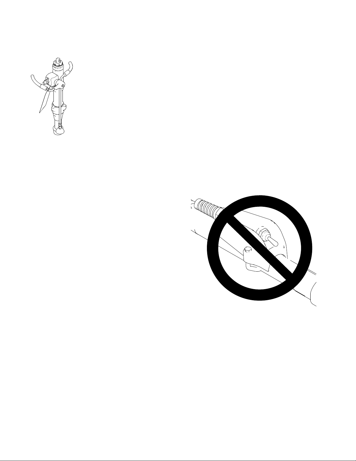
NOTE: If you suspect spray tip nozzle or hose is completely clogged or that pressure has not been fully
relieved after following the previous steps, cover the
connection at end of hose with a heavy rag and very
slowly loosen connection.
ti13050a
ti14632a
10 313888E
Page 11

Pressure Relief Procedure
Spray Gun (Top Coat Pump)
1. Lock gun trigger safety and turn engine OFF.
ti13131a
2. Turn on/off switch to OFF and turn pressure control
knob fully counterclockwise.
ti13050a
3. Unlock trigger safety. Hold metal part of gun firmly
to side of grounded metal pail and trigger gun to
relieve pressure.
ti10796b
4. Lock gun trigger safety. Open pressure prime/drain
valve. Leave valve open until ready to spray again.
ti13131a
ti14632a
NOTE: If you suspect that the spray tip nozzle or hose is
completely clogged, or that pressure has not been fully
relieved after following the previous steps, VERY
SLOWLY loosen the tip guard retaining nut or hose end
coupling to relieve pressure gradually, then loosen completely. Then clear tip or hose.
ti13130a
ti13128a
313888E 11
Page 12

Start Engine
Start Engine
1. Move fuel valve to OPEN.
ti5248a
2. Move choke to CLOSED.
5. Pull starter rope.
ti5263a
6. After engine starts, move choke to OPEN.
ti5264a
ti5249a
3. Set throttle to FAST.
ti5250a
4. Set engine switch to ON.
ti3315a
7. Set throttle to desired setting.
ti5251a
12 313888E
Page 13

Setup
Setup
NOTICE
DO NOT USE MATERIALS THAT CURE RAPIDLY!
Materials with a fast curing time could plug the pump,
hose, gun, or applicator.
1. Fill mixing pail with pre-mixed texture material. Mix
per material manufacturer instructions.
ti4118a
Add approximately 10% water to texture m ix or per material manufacturer instructio ns. Mix thoroughly.
2. Connect material hose to pump outlet.
ti14416a
ti13638a
Prime Pump
1. Start gasoline engine and adjust speed to half throttle. Turn prime/drain valve to DRAIN.
ti14632a
2. Place material hose outlet over supply pail.
ti13640a
3. Turn on/off switch ON.
Material and Sprayer Preparation
NOTE: To minimize material pack-out in hose when
priming, completely empty hose of all water. In hot conditions, it may be necessary to wet the hose with water
to lower internal hose temperature, slowing material
setup. In this case, water removal is still recommended.
If using hose lubricant/wetting solutions, refer to manufacturer instructions for proper priming techniques.
Cementicious and other curing materials can harden
within the drain valve while spraying. At least once per
hour stop spraying and open the drain valve to flush out
the older material.
3. Pour mixed material into supply pail under sprayer.
4. Place pump suction tube into mixed material.
NOTE: For best results with aggregate, remove strainer.
ti10795b
Base Coat Pump:
Also turn Prime switch ON, or activate applicator
switch on material hose.
4. Rotate pump control knob 1/4 turn. Run pump until
a steady stream of material flows from drain valve.
ti11930a
ti13652a
313888E 13
Page 14

Setup
5. Turn on/off switch OFF and turn drain valve knob to
SPRAY.
ti10796b
6. Turn on/off switch ON, and run pump until a steady
stream of material flows from material hose. Turn
on/off switch to OFF and turn drain valve knob to
DRAIN.
ti13649a
7. Connect applicator to material hose.
Spray With Airless Tip
1. Install filter and tip extension.
ti13648a
2. Insert metal seat and OneSeal. Insert Switch Tip.
Screw assembly onto applicator.
ti13650a
3. Turn drain valve to SPRAY, and turn on/off switch to
ON. Turn pump control knob clockwise and/or
adjust engine speed until desired material delivery
rate is achieved.
ti21038a
ti8794a
4. Spray test pattern. Aim applicator at floor. Turn
applicator switch ON and move applicator to spray
surface.
ti21042a
ti13651a
14 313888E
Page 15

Setup
Spray Without Air - Clear Clog
1. Relieve Pressure, page 10.
2. Rotate SwitchTip to Clear position. Aim applicator at
floor and turn pump ON. When clog clears, turn
pump OFF.
ti11714a
3. Rotate SwitchTip to Spray position. Turn pump ON.
Spray test pattern.
ti11715a
4. Turn air valve OFF. Connect applicator to material
hose and air hose. Air supply minimum requirements vary with material thickness and desired
thickness.
ti21037a
NOTICE
DO NOT USE MATERIALS THAT CURE RAPIDLY!
Materials with a fast curing time could plug the pump
hose, gun, or applicator.
5. Turn on/off switch ON.
Air Assisted Spray
(Base Coat Applicator)
1. Prepare material, page 13. Place material hose in
supply pail.
2. Turn on/off switch OFF.
ti10796b
3. Remove cap and install air valve assembly.
ti10795b
6. Hold applicator over material pail and turn pump ON
using applicator switch on hose.
ti13641a
7. Turn pump control clockwise until desired material
delivery rate is achieved.
ti13647a
313888E 15
ti8794a
ti5251a
Page 16

Setup
8. Spray test pattern. Aim applicator at floor. Turn air
valve ON. Move applicator to spray surface.
ti13646a
9. Adjust air valve and/or select alternative nozzle size
(4 - 10mm) for desired finish.
4 mm
6 mm
8 mm
10 mm
ti11798a
NOTICE
IF PUMP IS STOPPED LONGER THAN 3 MINUTES, TO AVOID PUMP PLUGGING:
• Relieve pressure in the pump (See Pressure
Relief procedure - page 10).
• Recirculate the material by pumping back into
original material container.
Air Assisted Spray
(Air Spray Trigger Gun)
3. Turn air valve OFF. Connect applicator to material
hose and air hose. Air supply minimum requirements vary with material thickness and desired
thickness.
ti21263a
NOTICE
DO NOT USE MATERIALS THAT CURE RAPIDLY!
Materials with a fast curing time could plug the pump
hose, gun, or applicator.
4. Turn on/off switch ON.
ti10795b
5. Hold applicator over material pail, trigger on, and
turn pump ON using applicator switch on hose.
NOTE: Remove spray disk then set material flow to
prevent material from back-flowing into air passages
of gun.
Due to the high pressure fluid emitted, a strong recoil
action may occur when you trigger this gun. If you are
unprepared, your hand could be forced back toward
your body or you could lose your balance and fall,
resulting in serious injury.
1. Prepare material, page 13. Place material hose in
supply pail.
6. Turn pump control clockwise and adjust engine
throttle to lowest setting until desired material deliv-
ti21243a
ery rate is achieved.
2. Turn on/off switch OFF.
ti10796b
ti8794a
16 313888E
Page 17

Setup
7. Turn air valve on and adjust air valve and/or select
alternative nozzles or spray discs to achieve desired
pattern.
1/8 in.
1/4 in.
3/8 in.
ti21034a
5/16 in.
8. Spray test pattern. Move applicator to spray surface. NOTE: See Air Spray Trigger Gun manual for
helpful hints on spray patterns.
NOTICE
• Keep gun triggered as much as possible to
prevent pack-out.
• If gun has not been triggered for longer than 3
minutes, perform Pressure Relief (page 10) in
the pump and hose to prevent packout.
• Turn off applicator switch on hose before detriggering to minimize retained pressure.
2. Screw assembly onto gun. Hand tighten.
ti5801a
3. Trigger gun and spray test pattern. Slowly adjust
pressure to eliminate heavy edges. Use smaller tip
size if pressure adjustment can not eliminate heavy
edges.
heavy
ti5823a
edges
4. Hold gun perpendicular, 10-12 in. (25-30 cm) from
surface. Spray back and forth. Use strokes overlapped by 50%. Start gun movement before triggering gun and release trigger before stopping gun
movement.
• Make sure air is flowing before triggering gun.
Spray Gun (Top Coat Pump)
1. Lock gun trigger safety. Insert seat and OneSeal™.
Insert SwitchTip.
ti13131a
SwitchTip
ti5800a
Seat
One seal
ti5824a
313888E 17
Page 18

Cleanup
Cleanup
1. Turn on/off switch OFF.
ti10796b
2. Perform Pressure Relief procedure, page 10.
3. Place pump in pail of clean water.
5. Base Coat Pump: Disconnect material hose from
pump outlet.
ti13639a
6. Insert wet cleaning ball into hose (Base Coat Only).
Connect material hose to pump outlet.
ti13644a
4. Shut OFF air if spraying with air. Remove applicator
from material and air hoses.
ti14284a
ti21040a
ti13643a
ti13638a
7. Hold material hose over waste pail.
ti13640a
8. Turn on/off switch ON and prime switch ON, or
applicator switch on material hose.
ti10795b
18 313888E
Page 19

Cleanup
9. Run pump until cleaning ball exits material hose.
Save cleaning ball (Base Coat Only).
ti4551c
10. Turn on/off switch OFF and turn prime/drain valve to
DRAIN. Clean outside of pump and suction tube
with brush and water.
ti10796b
ti14632a
11. Connect applicator to material hose. Close
prime/drain valve.
14. Add additional water and repeat steps 12 - 13 if necessary.
ti13839a
15. Open prime/drain valve and turn prime switch ON to
flush valve.
ti14632a
ti21038a
12. Turn on/off switch ON.
Base Coat Pump: Turn prime switch ON, or applicator switch on material hose.
ti10795b
13. Run pump until clean water flows from applicator.
16. Turn on/off switch OFF when valve is thoroughly
flushed.
ti10796b
17. Open over pressure relief valve and turn prime
switch ON to flush valve.
ti13633a
ti13641a ti21039a
313888E 19
Page 20

Cleanup
18. Remove and thoroughly clean applicator, spray tip
nozzle and guard with brush.
19. Turn on/off switch OFF when valve is thoroughly
flushed.
NOTICE
Do not use air nozzle cleaner to clean applicator
check valve or airless spray tip nozzle. Damage will
occur.
20. Clean hardened material from applicator nozzles
with air nozzle cleaner.
ti11810a
ti11811a
Remove air check valve from applicator to clean
hardened material from interior of applicator.
ti13642a
ti21035a
20 313888E
Page 21

Digital Tracking System (DTS)
Digital Tracking System (DTS)
Main Menu
Close cover when spraying to protect display.
ti5802a
1. Perform Startup steps 1 - 2.
• Open drain valve
• Turn pump control counterclockwise to lowest set-
ting
• Set applicator switch to OFF
2. Start Engine, page 12. Display will momentarily
show which pump is installed (Base or Top) and
then Flow 1, 2, or 3 (if Base Coat pump is installed).
Pressure display appears, then dashes appear
when pressure is less than 60 psi (4 bar, 0.4 MPa).
ti5804a
4. Short press DTS button to move to Engine RPM.
ti13761a
5. Short press DTS button to return to Pressure.
ti13762a
To Change Pressure Units:
Press and hold (8 seconds) DTS button to change pressure unit (psi, bar, MPa).
Continue to press DTS button to cycle from psi to bar to
MPa. Release DTS button to select units.
psi
NOTE: Information other than pressure cannot be
accessed if applicator switch is ON. And, if system pressure is greater than 200 psi (14 bar, 1.4 MPa), the display will revert back to pressure after 3 seconds.
3. Short press DTS button to display installed pump.
ti13760a
bar
MPa
psi
ti6225a
313888E 21
Page 22

Digital Tracking System (DTS)
Secondary Menu - Stored Data
Mode
• Open drain valve
• Turn pump control counterclockwise to lowest set-
ting
• Set applicator switch to OFF
1. Start Engine, page 12. Pressure display appears.
ti5812a
2. Press and hold DTS button and turn applicator
switch ON.
ti13764a
6. Short press DTS button and Base Coat hours displays.
Short press DTS button and Top Coat hours display.
Short press DTS button and Engine hours display.
ti13787a
7. Short press DTS button and LAST ERROR scrolls
through display followed by stored error message
and error code. This information cycles repeatedly
until cleared.
See page 23 for error code explanations.
3. SERIAL NUM scrolls through display and a 3 to
5-digit serial number displays.
ti6213a
4. Short press DTS button and date code displays.
ti6215a
5. Short press DTS button and part number displays.
ti6220a
8. Press and hold DTS button until CLEAR ERROR
NO ERROR CODE scrolls through the display and
error code E=00 displays.
ti6218a
9. Short press DTS button again and SOFTWARE
REV scrolls through display followed by revision
level (for example 10102).
ti13788a
10. Short press to return to step 3. Turn on/off switch
OFF at any time to exit stored data mode.
ti13786a
ti5822a
22 313888E
Page 23

Digital Display Messages
DISPLAY* SPRAYER OPERATION INDICATION ACTION
No Display Sprayer may be
pressurized
Sprayer may be
ti6314a
BASE
or
pressurized
Displays installed pump
when engine is started
TOP
OFF
FLOW 1
FLOW 2
or
Displays flow control
setting in Base Coat mode
when pump control setting
is changed
FLOW 3
psi
bar
MPa
ti6315a
Sprayer is pressurized.
Power is applied. (Pressure
varies with tip size and
pressure control setting.)
Top Coat Only:
stops. Engine is running.
ti6316a
Sprayer stops. Engine is
running.
ti6317a
Sprayer stops. Engine is
running.
ti6318a
Sprayer
Loss of power or
display not connected
Pressure less than
Check power source. Relieve pressure before repair
or disassembly. Verify display is connected.
Increase pressure as needed
60 psi (4 bar, 0.4 MPa)
Normal operation Spray
Normal operation
Spray
(with Base Coat pump)
Normal operation Spray
Pressure greater than
4500 psi (310 bar, 31
MPa)
1 Check fluid path for clogs.
2 Use Graco paint hose, 3/8 in. x 50 ft minimum.
Smaller hose or metal braid hose may result in
pressure spikes.
3 Replace transducer if fluid path is not clogged and
proper hose is used.
Pressure transducer
faulty, bad connection
or broken wire
1 Check transducer connection.
2 Disconnect and reconnect transducer plug to
ensure good connection with control board
socket.
3 Open prime valve. Replace sprayer transducer
with known good transducer and run sprayer.
Replace transducer if sprayer runs or control
board if sprayer does not run.
High clutch current 1 Check wiring connections.
2
Measure:
1.7 + 0.2Ω across clutch field at 70°F.
3 Replace clutch field assembly.
Digital Display Messages
Base Coat Only:
stops. Engine is running.
Sprayer
Pressure greater than
1000 psi (69 bar, 6.9
MPa)
1 Open prime valve and gun.
2 Verify no flow obstructions. Use Graco texture
hoses 3/4 in. x 50 ft minimum.
3 Replace transducer if fluid path is not clogged and
proper hose is used.
* Error codes also appear on control board as a blinking red
LED. LED is an alternate to digital messages.
1 Remove two screws (71) and swing down cover (130).
2 Start engine. Blink count is the same as error code(E=0X).
After a fault, follow these steps to restart sprayer:
1 Correct fault condition.
2 Turn sprayer OFF.
3 Turn sprayer ON.
(E02 and E06 errors will self-correct when system is reduced)
313888E 23
Page 24

Maintenance
Maintenance
NOTICE
For detailed engine maintenance and specifications,
refer to separate Honda Engines Owner’s Manual
(supplied).
DAILY
AFTER EACH 100 HOURS OF OPERATION
• Change engine oil. Reference Honda Engines
Owner’s Manual for correct oil viscosity.
SPARK PLUG
Use only BPR6ES (NGK) or W20EPR-U (NIPPONDENSO) plug. Gap plug to 0.028 to 0.031 in. (0.7 to 0.8
mm). Use spark plug wrench when installing and removing plug.
• Check engine oil level and fill as necessary
• Check hose for wear and damage
• Check that all hose fittings are secure
• Check gun safety for proper operation
• Check and fill the gas tank
• Check level of TSL in displacement pump packing
nut. Fill nut, if necessary. Keep TSL in nut to help
prevent fluid buildup on piston rod and premature
wear of packings and pump corrosion.
AFTER FIRST 20 HOURS OF OPERATION
• Drain engine oil and refill with clean oil. Reference
Honda Engines Owner’s Manual for correct oil viscosity.
WEEKLY
• Remove engine air filter cover and clean element.
Replace element if necessary. If operating in an
unusually dusty environment, check filter daily and
replace (if necessary).
ENGINE OIL FUNNEL
• Use the supplied engine oil funnel when draining oil.
ti6200a
Replacement elements can be purchased from your
local Honda dealer.
24 313888E
Page 25

Technical Data
Technical Data
Honda GX 200 Engine:
ANSI Power Rating @ 3600 rpm 6.5 Horsepower (4.8 kW)
Maximum Working Pressure:
Base Coat Pump 1000 psi (69 bar, 6.9 MPa)
Top Coat Pump 3300 psi (228 bar, 22.8 MPa)
Noise Level:
Sound Power 105 dBa per ISO 3744
Sound Pressure 96 dBa measured at 3.1 ft (1 m)
Maximum Delivery Rating:
Base Coat Pump 3.0 gpm (11.36 liter/min)
Top Coat Pump 2.20 gpm (8.33 liter/min)
Maximum Tip Size:
Base Coat Pump 1 applicator with .071 in. tip or 10 mm Nozzle
Top Coat Pump 1 gun with 0.048 in. tip
2 guns with 0.035 in. tip
3 guns with 0.027 in. tip
4 guns with 0.023 in. tip
Inlet Paint Strainer:
Base Coat Pump 2 in. npsm, #5 mesh sst
Top Coat Pump 1 in. npsm, #8 mesh sst
Pump Inlet Size:
Base Coat Pump 2 in. QD Camlock male coupler
Top Coat Pump 1 in. - 11.5 npsm
Fluid Outlet Size:
Base Coat Pump 1 in. QD Camlock male coupler
Top Coat Pump 3/8 npsm
Wetted Parts:
zinc-plated carbon steel, PTFE, nylon, polyurethane, UHMW, polyethyl-
ene, fluoroelastomer, acetal, leather, aluminum, tungsten carbide,
nickel- and zinc-plated carbon steel, stainless steel, chrome plating
Dimensions
Part Weight lb (kg) Height in. (cm) Width in. (cm) Length in. (cm)
HTX 2030 Sprayer 155 (70.5) 34.25 (87.0) 24.5 (62.2) 33.0 (83.8)
3/4 in. Hose 29 (13.2) — — —
Applicator/Swivel 3 (1.3) — — —
HTX2030 Air Spray Trigger Gun 3.65 (1.7) 12 (30.5) 1.7 (2.5) 10.4 (26.4)
313888E 25
Page 26

Notes
Notes
26 313888E
Page 27

Notes
Notes
313888E 27
Page 28

Graco Standard Warranty
Graco warrants all equipment referenced in this document which is manufactured by Graco and bearing its name to be free from defects in
material and workmanship on the date of sale to the original purchaser for use. With the exception of any special, extended, or limited warranty
published by Graco, Graco will, for a period of twelve months from the date of sale, repair or replace any part of the equipment determined by
Graco to be defective. This warranty applies only when the equipment is installed, operated and maintained in accordance with Graco’s written
recommendations.
This warranty does not cover, and Graco shall not be liable for general wear and tear, or any malfunction, damage or wear caused by faulty
installation, misapplication, abrasion, corrosion, inadequate or improper maintenance, negligence, accident, tampering, or substitution of
non-Graco component parts. Nor shall Graco be liable for malfunction, damage or wear caused by the incompatibility of Graco equipment with
structures, accessories, equipment or materials not supplied by Graco, or the improper design, manufacture, installation, operation or
maintenance of structures, accessories, equipment or materials not supplied by Graco.
This warranty is conditioned upon the prepaid return of the equipment claimed to be defective to an authorized Graco distributor for verification of
the claimed defect. If the claimed defect is verified, Graco will repair or replace free of charge any defective parts. The equipment will be returned
to the original purchaser transportation prepaid. If inspection of the equipment does not disclose any defect in material or workmanship, repairs
will be made at a reasonable charge, which charges may include the costs of parts, labor, and transportation.
THIS WARRANTY IS EXCLUSIVE, AND IS IN LIEU OF ANY OTHER WARRANTIES, EXPRESS OR IMPLIED, INCLUDING BUT NOT LIMITED
TO WARRANTY OF MERCHANTABILITY OR WARRANTY OF FITNESS FOR A PARTICULAR PURPOSE
Graco’s sole obligation and buyer’s sole remedy for any breach of warranty shall be as set forth above. The buyer agrees that no other remedy
(including, but not limited to, incidental or consequential damages for lost profits, lost sales, injury to person or property, or any other incidental or
consequential loss) shall be available. Any action for breach of warranty must be brought within two (2) years of the date of sale.
GRACO MAKES NO WARRANTY, AND DISCLAIMS ALL IMPLIED WARRANTIES OF MERCHANTABILITY AND FITNESS FOR A
PARTICULAR PURPOSE, IN CONNECTION WITH ACCESSORIES, EQUIPMENT, MATERIALS OR COMPONENTS SOLD BUT NOT
MANUFACTURED BY GRACO
the warranty, if any, of their manufacturer. Graco will provide purchaser with reasonable assistance in making any claim for breach of these
warranties.
In no event will Graco be liable for indirect, incidental, special or consequential damages resulting from Graco supplying equipment hereunder, or
the furnishing, performance, or use of any products or other goods sold hereto, whether due to a breach of contract, breach of warranty, the
negligence of Graco, or otherwise.
FOR GRACO CANADA CUSTOMERS
The Parties acknowledge that they have required that the present document, as well as all documents, notices and legal proceedings entered into,
given or instituted pursuant hereto or relating directly or indirectly hereto, be drawn up in English. Les parties reconnaissent avoir convenu que la
rédaction du présente document sera en Anglais, ainsi que tous documents, avis et procédures judiciaires exécutés, donnés ou intentés, à la suite
de ou en rapport, directement ou indirectement, avec les procédures concernées.
. These items sold, but not manufactured by Graco (such as electric motors, switches, hose, etc.), are subject to
.
Graco Information
For the latest information about Graco products, visit www.graco.com.
TO PLACE AN ORDER, contact your Graco distributor or call 1-800-690-2894 to identify the nearest distributor.
All written and visual data contained in this document reflects the latest product information available at the time of publication.
Graco reserves the right to make changes at any time without notice.
This manual contains English. MM 313888
International Offices:
Graco Headquarters:
Belgium, China, Japan, Korea
Minneapolis
GRACO INC. P.O. BOX 1441 MINNEAPOLIS, MN 55440-1441
Copyright 2008, Graco Inc. is registered to I.S. EN ISO 9001
www.graco.com
Revision E - March 2013
 Loading...