

Page 1
Instructions
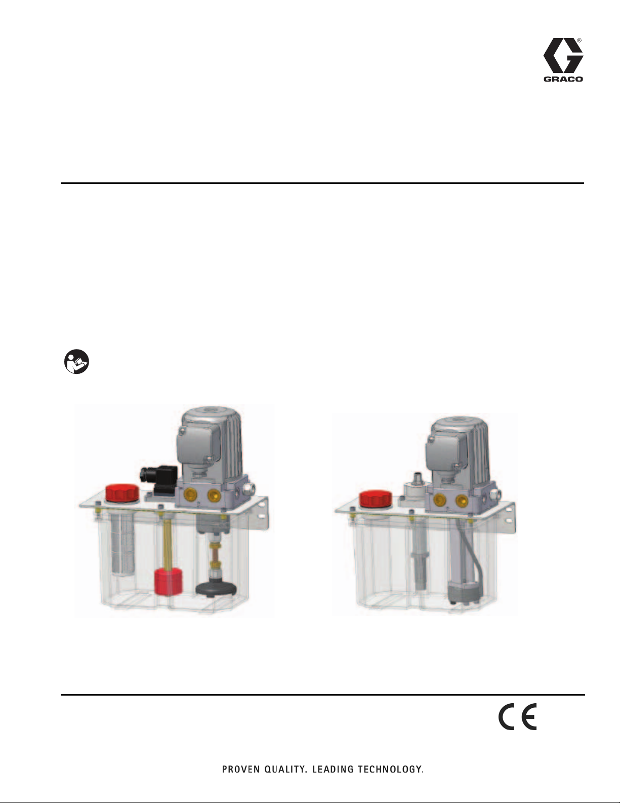
Injecto-Flo II Single Line
Pumps with No Control
- For feeding volumetric dosing meters in a single-line system -
- Not for use in hazardous locations -
Part No.: See page 2
OIL: 435 psi (3.0 MPa, 30 bar) Maximum Working Pressure
GREASE: 580 psi (4.0 MPa, 40 bar) Maximum Working Pressure
313839C
EN
Important Safety Instructions
Read all warnings and instructions in this
manual. Save these instructions.
Oil Model Grease Model
Page 2

Models
Models
Oil Systems
Reservoir
Model CE
122545 ✓ 0.8 (3.0) 0.05 (0.2) None Screw Cap
122546 ✓ 0.8 (3.0) 0.05 (0.2) None
122547 ✓ 0.8 (3.0) 0.13 (0.5) None Screw Cap
122548 ✓ 0.8 (3.0) 0.13 (0.5) None
122549 ✓ 0.8 (3.0) 0.05 (0.2) Single w/DIN Screw Cap
122550 ✓ 0.8 (3.0) 0.05 (0.2) Single w/DIN
122551 ✓ 0.8 (3.0) 0.13 (0.5) Single w/DIN Screw Cap
122552 ✓ 0.8 (3.0) 0.13 (0.5) Single w/DIN
122553 ✓ 0.8 (3.0) 0.05 (0.2) Single w/M12 Top Screw Cap
15U859 0.8 (3.0) 0.05 (0.2) Single w/M12 Top
122554 ✓ 0.8 (3.0) 0.13 (0.5) Single w/M12 Top Screw Cap
122555 ✓ 0.8 (3.0) 0.13 (0.5) Single w/M12 Top
122556 ✓ 0.8 (3.0) 0.05 (0.2) Dual w/DIN Screw Cap
122557 ✓ 0.8 (3.0) 0.05 (0.2) Dual w/DIN
122558 ✓ 0.8 (3.0) 0.13 (0.5) Dual w/DIN Screw Cap
122559 ✓ 0.8 (3.0) 0.13 (0.5) Dual w/DIN
Gal (liters)
Flow
GPM (lpm) Level Switch Refill System
Straight Connector (
Straight Connector (
Straight Connector (
Straight Connector (
Straight Connector (
Straight Connector (
Straight Connector (
Straight Connector (
∅ 10 pipe)
∅ 10 pipe)
∅ 10 pipe)
∅ 10 pipe)
∅ 10 pipe)
∅ 10 pipe)
∅ 10 pipe)
∅ 10 pipe)
122560 ✓ 0.8 (3.0) 0.05 (0.2) Dual w/M12 Top Screw Cap
122561 ✓ 0.8 (3.0) 0.05 (0.2) Dual w/M12 Top
122562 ✓ 0.8 (3.0) 0.13 (0.5) Dual w/M12 Top Screw Cap
122840 ✓ 0.8 (3.0) 0.13 (0.5) Dual w/M12 Top
122563 ✓ 1.6 (6.0) 0.05 (0.2) None Screw Cap
122564 ✓ 1.6 (6.0) 0.05 (0.2) None
122565 ✓ 1.6 (6.0) 0.13 (0.5) None Screw Cap
122566 ✓ 1.6 (6.0) 0.13 (0.5) None
122567 ✓ 1.6 (6.0) 0.05 (0.2) Single w/DIN Screw Cap
122568 ✓ 1.6 (6.0) 0.05 (0.2) Single w/DIN
564138 1.6 (6.0) 0.05 (0.2) Single w/DIN Screw Cap
122569 ✓ 1.6 (6.0) 0.05 (0.2) Single w/DIN
122570 ✓ 1.6 (6.0) 0.05 (0.2) Single w/M12 Top Screw Cap
122571 ✓ 1.6 (6.0) 0.05 (0.2) Single w/M12 Top
122572 ✓ 1.6 (6.0) 0.13 (0.5) Single w/M12 Top Screw Cap
122573 ✓ 1.6 (6.0) 0.13 (0.5) Single w/M12 Top
Straight Connector (
Straight Connector (
Straight Connector (
Straight Connector (
Straight Connector (
Straight Connector (
Straight Connector (
Straight Connector (
∅ 10 pipe)
∅ 10 pipe)
∅ 10 pipe)
∅ 10 pipe)
∅ 10 pipe)
∅ 10 pipe)
∅ 10 pipe)
∅ 10 pipe)
2 313839C
Page 3

Models
Reservoir
Model CE
122574 ✓ 1.6 (6.0) 0.05 (0.2) Dual w/DIN Screw Cap
122575 ✓ 1.6 (6.0) 0.05 (0.2) Dual w/DIN
122576 ✓ 1.6 (6.0) 0.13 (0.5) Dual w/DIN Screw Cap
122577 ✓ 1.6 (6.0) 0.13 (0.5) Dual w/DIN
122578 ✓ 1.6 (6.0) 0.05 (0.2) Dual w/M12 Top Screw Cap
122579 ✓ 1.6 (6.0) 0.05 (0.2) Dual w/M12 Top
122580 ✓ 1.6 (6.0) 0.13 (0.5) Dual w/M12 Top Screw Cap
15U860 1.6 (6.0) 0.05 (0.2 Dual w/M12 Top
Gal (liters)
Flow
GPM (lpm) Level Switch Refill System
Straight Connector (
Straight Connector (
Straight Connector (
Straight Connector (
Grease Systems
Reservoir
Model CE
122581 ✓ 0.8 (3.0) 0.05 (0.2) None Screw Cap
563301 0.8 (3.0) 0.05 (0.2) None
Gal (liters)
Flow
GPM (LPM) Level Switch Refill System
Straight Connector (
∅ 10 pipe)
∅ 10 pipe)
∅ 10 pipe)
∅ 10 pipe)
∅ 10 pipe)
122582 ✓ 0.8 (3.0) 0.13 (0.2) Single w/DIN Screw Cap
122583 ✓ 0.8 (3.0) 0.13 (0.2) Single w/DIN
122584 ✓ 0.8 (3.0) 0.13 (0.2) Single w/M12 Top Screw Cap
122585 ✓ 0.8 (3.0) 0.13 (0.2) Single w/M12 Top
122586 ✓ 0.8 (3.0) 0.13 (0.2) Dual w/DIN Screw Cap
122587 ✓ 0.8 (3.0) 0.13 (0.2) Dual w/DIN
122588 ✓ 0.8 (3.0) 0.13 (0.2) Dual w/M12 Top Screw Cap
557547 0.8 (3.0) 0.13 (0.2) Dual w/M12 Top
122589 ✓ 1.6 (6.0) 0.13 (0.2) None Screw Cap
122590 ✓ 1.6 (6.0) 0.13 (0.2) None
122591 ✓ 1.6 (6.0) 0.13 (0.2) Single w/DIN Screw Cap
122592 ✓ 1.6 (6.0) 0.13 (0.2) Single w/DIN
122593 ✓ 1.6 (6.0) 0.13 (0.2) Single w/M12 Top Screw Cap
122594 ✓ 1.6 (6.0) 0.13 (0.2) Single w/M12 Top
122595 ✓ 1.6 (6.0) 0.13 (0.2) Dual w/DIN Screw Cap
122596 ✓ 1.6 (6.0) 0.13 (0.2) Dual w/DIN
122597 ✓ 1.6 (6.0) 0.13 (0.2) Dual w/M12 Top Screw Cap
122598 ✓ 1.6 (6.0) 0.13 (0.2) Dual w/M12 Top
Straight Connector (
Straight Connector (
Straight Connector (
Straight Connector (
Straight Connector (
Straight Connector (
Straight Connector (
Straight Connector (
Straight Connector (
∅ 10 pipe)
∅ 10 pipe)
∅ 10 pipe)
∅ 10 pipe)
∅ 10 pipe)
∅ 10 pipe)
∅ 10 pipe)
∅ 10 pipe)
∅ 10 pipe)
313839C 3
Page 4
Warnings
Warnings
The following warnings are for the setup, use, grounding, maintenance, and repair of this equipment. The exclamation point symbol alerts you to a general warning and the hazard symbol refers to procedure-specific risk. Refer back
to these warnings. Additional, product-specific warnings may be found throughout the body of this manual where
applicable.
WARNING
FIRE AND EXPLOSION HAZARD
When flammable fluids are present in the work area, such as gasoline and windshield wiper fluid, be
aware that flammable fumes can ignite or explode. To help prevent fire and explosion:
• Use equipment only in well ventilated area.
• Eliminate all ignition sources, such as cigarettes and portable electric lamps.
• Keep work area free of debris, including rags and spilled or open containers of solvent and gasoline.
• Do not plug or unplug power cords or turn lights on or off when flammable fumes are present.
• Ground all equipment in the work area.
• Use only grounded hoses.
• If there is static sparking or you feel a shock, stop operation immediately. Do not use equipment
until you identify and correct the problem.
• Keep a working fire extinguisher in the work area.
ELECTRIC SHOCK HAZARD
This equipment must be grounded. Improper grounding, setup, or usage of the system can cause
electric shock.
• Turn off and disconnect power at main switch before disconnecting any cables and before servicing
equipment.
• Connect only to grounded power source.
• All electrical wiring must be done by a qualified electrician and comply with all local codes and
regulations.
PRESSURIZED EQUIPMENT HAZARD
Fluid from the gun/dispense valve, leaks, or ruptured components can splash in the eyes or on skin and
cause serious injury.
• Follow Pressure Relief Procedure in this manual, when you stop spraying and before cleaning,
checking, or servicing equipment.
• Tighten all fluid connections before operating the equipment.
• Check hoses, tubes, and couplings daily. Replace worn or damaged parts immediately.
EQUIPMENT MISUSE HAZARD
Misuse can cause death or serious injury.
• Do not operate the unit when fatigued or under the influence of drugs or alcohol.
• Do not exceed the maximum working pressure or temperature rating of the lowest rated system
component. See Technical Data in all equipment manuals.
• Check equipment daily. Repair or replace worn or damaged parts immediately with genuine manufacturer’s replacement parts only.
• Do not alter or modify equipment.
• Use equipment only for its intended purpose. Call your distributor for information.
• Route hoses and cables away from traffic areas, sharp edges, moving parts, and hot surfaces.
• Do not kink or over bend hoses or use hoses to pull equipment.
• Keep children and animals away from work area.
• Comply with all applicable safety regulations.
4 313839C
Page 5
Grounding
The equipment must be grounded. Grounding reduces
the risk of static and electric shock by providing an
escape wire for the electrical current due to static build
up or in the event of a short circuit.
Pressure Relief Procedure
To relieve pressure, loosen outlet fitting connection to
bleed air and relieve pressure.
Warnings
NOTE: Pumps have a built-in decompression valve that
relieves pressure when cycle is complete.
313839C 5
Page 6

Installation
Installation
Component Identification
Doser
B
G
D
Doser
C
J
G
A
A
D
Hydraulic Diagram
H
F
E
B
C
FIG. 1
Key: Grease Models
ATank
B Electric Motor
CGear Pump
D Electric Level Switch
E Pressure Limiting Valve
FRelief Valve
G Filling Cap-Filter
H Pressure Outlet
6 313839C
Oil Models*
(includes all items A - H and also the following)
J Suction Filter
Page 7

Refilling Options
Oil Systems (FIG. 2) Grease Systems (FIG. 3)
Installation
A
C
D
C
F
IG. 2
A Screw Cap Option
B Elbow Connector Option
C Screw Cap
D Strainer Basket (Oil Models Only)
E Down Tube (Oil Models Only)
F Vent (additional information)
G Elbow Connector
E
F
G
A
B
C
F
C
G
B
D
H
FIG. 3
Vent (FIG. 4)
NOTE: A vent is included with all units with refilling systems using a connector (G).
F
IG. 4
F
313839C 7
Page 8

Installation
Level Switch Connector Options
Oil Systems
A
F
IG. 5
A Standard Connector Option: Minimal level with standard DIN connector; Minimum + Prealarm level with standard DIN
connector.
B M12 Connector Top Entry Option: Minimum level with M12 connector top entry; Minimum + Premalarm level with M12
connector top entry.
B
A
Grease Systems
B
Instructions
The control of these units is external (without control) programming by the machine automatism or external control
(CNC, Automatic device, etc.).
It can be equipped with an electrical level (minimum level) control in the tank.
8 313839C
Page 9

Electrical Diagram
Electrical Diagram
W2U2V
U1V1W
L1 L2
1
L3
231
Oil
MIN.
PRE.
3
2
1
2
W
2U2V2
1V1W1
U
L1 L2
L3
W2U2V
U1V1W
L1 N
2
1
MIN.
Grease
PNP
BN
BK
BU
+
-
313839C 9
Page 10

Replacement Parts Available from Graco
Replacement Parts Available from Graco
Part No. Description
122901 PUMP, electric motor, oil, 0.2L/min
122902 PUMP, electric motor, oil, 0.5L/min
122903 SWITCH, min level w/din, 3L
122904 SWTICH, min level w/din, 6L
122905 SWITCH, min, prealarm level, w/din, 3L
122906 SWITCH, min, prealarm level, w/din, 6L
122907 SWITCH, min level w/M12, 3L
122908 SWITCH, min level w/M12, 6L
122909 SWITCH, min prealarm level w/M12, 3L
122910 SWITCH, min prealarm level w/M12, 3L
122911 RESERVOIR, 3 Liter, no cover
122912 CAP, screw
122913 FILTER, refilling
122914 FILTER, suction, 3L, reservoir
122915 FILTER, suction, 6L, reservoir
122916 PUMP, electric motor, grease, 3L
122917 PUMP, electric motor, grease, 6L
122918 SWITCH, min level w/din, 3L
122919 SWTICH, min level w/din, 6L
122920 SWITCH, min, prealarm level, w/din, 3L
Part No. Description
122921 SWITCH, min, prealarm level, w/din, 6L
122922 SWITCH, min level w/M12, 3L
122923 SWITCH, min level w/M12, 6L
122924 SWITCH, min prealarm level w/M12, 3L
122925 SWITCH, min prealarm level w/M12, 3L
15X624 MANIFOLD, tee, M8
15X625 MANIFOLD, tee, M10
15X626 MANIFOLD, tee, M14
15X667 MANIFOLD, M10/M8 2 station
15X668 MANIFOLD, M10/M8 3 station
15X669 MANIFOLD, M10/M8 4 station
15X670 MANIFOLD, M10/M8 5 station
15X671 MANIFOLD, M10/M8 6 station
15X672 MANIFOLD, M10/M8 7 station
15X673 MANIFOLD, M10/M8 8 station
189930 LABEL, warning, electric shock ▲
▲ Replacement Danger and Warning labels, tags, and
cards are available at no cost.
10 313839C
Page 11

Technical Data
Tank Capacity
Models: Oil . . . . . . . . . . . . . . . . . . . . . . . . . . . . . . . . . 0.8 - 1.6 gallons (3 - 6 liters)
Models: Grease . . . . . . . . . . . . . . . . . . . . . . . . . . . . . 1.6 gallons (6 liters)
Tank Material. . . . . . . . . . . . . . . . . . . . . . . . . . . . . . . . . . Transparent Polymide
Output Connection. . . . . . . . . . . . . . . . . . . . . . . . . . . . . M14 x 1.5
Pump
Lubricant
Models: Oil . . . . . . . . . . . . . . . . . . . . . . . . . . . . . . . . . Mineral or synthetic oil
Models: Grease . . . . . . . . . . . . . . . . . . . . . . . . . . . . . Fluid grease NLGI00-000
Flow . . . . . . . . . . . . . . . . . . . . . . . . . . . . . . . . . . . . . . . . . 0.05 - 0.13 gal/min (0.2 - 0.5 L/min)
Maximum Pressure
Oil. . . . . . . . . . . . . . . . . . . . . . . . . . . . . . . . . . . . . . . . 435 psi (3.0 MPa, 30 bar)
Grease . . . . . . . . . . . . . . . . . . . . . . . . . . . . . . . . . . . . 580 psi (4.0 MPa, 40 bar)
Working Temperature
Lubricant . . . . . . . . . . . . . . . . . . . . . . . . . . . . . . . . . . 140°F (60°C)
Ambient (Oil models only) . . . . . . . . . . . . . . . . . . . . . 104°F (40°C)
A/C Motor
Voltage / Frequency . . . . . . . . . . . . . . . . . . . . . . . . . . . . . 230/400 VAC, 50/60 Hz, 0.5 - 0.3A
Consumption . . . . . . . . . . . . . . . . . . . . . . . . . . . . . . . . . . 70W
Technical Data
313839C 11
Page 12

Technical Data
Dimensions
11.3 in.
(289 mm)
5.37 in.
(136.5 mm)
_
6 in.
(152.5 mm)
5.59 in
(142 mm)
8.6 & 9.0 in.
(220 & 230 mm)
9.65 in.
(245 mm)
_
12 313839C
Page 13

Notes
Notes
313839C 13
Page 14

Graco Standard Warranty
Graco warrants all equipment referenced in this document which is manufactured by Graco and bearing its name to be free from defects in
material and workmanship on the date of sale to the original purchaser for use. With the exception of any special, extended, or limited warranty
published by Graco, Graco will, for a period of twelve months from the date of sale, repair or replace any part of the equipment determined by
Graco to be defective. This warranty applies only when the equipment is installed, operated and maintained in accordance with Graco’s written
recommendations.
This warranty does not cover, and Graco shall not be liable for general wear and tear, or any malfunction, damage or wear caused by faulty
installation, misapplication, abrasion, corrosion, inadequate or improper maintenance, negligence, accident, tampering, or substitution of
non-Graco component parts. Nor shall Graco be liable for malfunction, damage or wear caused by the incompatibility of Graco equipment with
structures, accessories, equipment or materials not supplied by Graco, or the improper design, manufacture, installation, operation or
maintenance of structures, accessories, equipment or materials not supplied by Graco.
This warranty is conditioned upon the prepaid return of the equipment claimed to be defective to an authorized Graco distributor for verification of
the claimed defect. If the claimed defect is verified, Graco will repair or replace free of charge any defective parts. The equipment will be returned
to the original purchaser transportation prepaid. If inspection of the equipment does not disclose any defect in material or workmanship, repairs will
be made at a reasonable charge, which charges may include the costs of parts, labor, and transportation.
THIS WARRANTY IS EXCLUSIVE, AND IS IN LIEU OF ANY OTHER WARRANTIES, EXPRESS OR IMPLIED, INCLUDING BUT NOT LIMITED
TO WARRANTY OF MERCHANTABILITY OR WARRANTY OF FITNESS FOR A PARTICULAR PURPOSE.
Graco’s sole obligation and buyer’s sole remedy for any breach of warranty shall be as set forth above. The buyer agrees that no other remedy
(including, but not limited to, incidental or consequential damages for lost profits, lost sales, injury to person or property, or any other incidental or
consequential loss) shall be available. Any action for breach of warranty must be brought within two (2) years of the date of sale.
GRACO MAKES NO WARRANTY, AND DISCLAIMS ALL IMPLIED WARRANTIES OF MERCHANTABILITY AND FITNESS FOR A
PARTICULAR PURPOSE, IN CONNECTION WITH ACCESSORIES, EQUIPMENT, MATERIALS OR COMPONENTS SOLD BUT NOT
MANUFACTURED BY GRACO. These items sold, but not manufactured by Graco (such as electric motors, switches, hose, etc.), are subject to
the warranty, if any, of their manufacturer. Graco will provide purchaser with reasonable assistance in making any claim for breach of these
warranties.
In no event will Graco be liable for indirect, incidental, special or consequential damages resulting from Graco supplying equipment hereunder, or
the furnishing, performance, or use of any products or other goods sold hereto, whether due to a breach of contract, breach of warranty, the
negligence of Graco, or otherwise.
FOR GRACO CANADA CUSTOMERS
The Parties acknowledge that they have required that the present document, as well as all documents, notices and legal proceedings entered into,
given or instituted pursuant hereto or relating directly or indirectly hereto, be drawn up in English. Les parties reconnaissent avoir convenu que la
rédaction du présente document sera en Anglais, ainsi que tous documents, avis et procédures judiciaires exécutés, donnés ou intentés, à la suite
de ou en rapport, directement ou indirectement, avec les procédures concernées.
Graco Information
For the latest information about Graco products, visit www.graco.com.
TO PLACE AN ORDER, contact your Graco distributor or call to identify the nearest distributor.
Phone: 612-623-6928 or Toll Free: 1-800-533-9655, Fax: 612-378-3590
All written and visual data contained in this document reflects the latest product information available at the time of publication.
Graco reserves the right to make changes at any time without notice.
Original instructions. This manual contains English. MM 313389
Graco Headquarters: Minneapolis
International Offices: Belgium, China, Japan, Korea
GRACO INC. P.O. BOX 1441 MINNEAPOLIS, MN 55440-1441
Copyright 2009, Graco Inc. is registered to ISO 9001
www.graco.com
5/2009, revised 1/2012
 Loading...