

Page 1
Operation
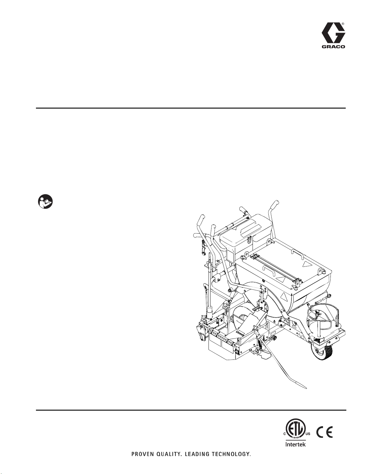
ThermoLazer™ Pavement Marking System
US Patent No. D619,625 S
- For professional application of thermoplastic traffic marking compound materials
(reflective beads applied simultaneously with screeding) -
- For outdoor use only (not to be operated in rain or damp conditions) -
Model No. 258699 North America - Includes 257500 and 4 in. (10 cm) SmartDie
™
Model No. 257500 International (SmartDie
Fuel: LP Gas (Propane Vapor)
Burner capacities (max total): 138,000 BTU/hr. (40.44 kW) [38,000 BTU/hr. (7.03 kW) without torch]
Material capacity (max): 300 lb (136 kg)
IMPORTANT SAFETY INSTRUCTIONS
Read all warnings and instructions in this
manual. Save these instructions.
Related Manuals
Repair 313879
Parts 313880
™
For use with the following SmartDie
Part Description
24F630 3 IN. (8 cm) Screed Box
256736 4 in. (10 cm) Screed Box
257469 5 in. (12 cm) Screed Box
256737 6 in. (15 cm) Screed Box
257470 7 in. (18 cm) Screed Box
256738 8 in. (20 cm) Screed Box
257471 9 in. (22.5 cm) Screed Box
257472 10 in. (26 cm) Screed Box
256739 12 in. (30 cm) Screed Box
256799 Double Line 4-4-4 in. (10-10-10 cm) Screed Box
24B729 Double Line 4-3-4 in. (10-8-10 cm) Screed Box
24F631 Double Line 3-3-3 in. (8-8-8 cm) Screed Box
Screed Box:
Screed Box not included)
™
Screed Box
257500
313787C
ENG
24C528 Double Bead Box Kit
ti14144a
Page 2

Table of Contents
Table of Contents
Table of Contents . . . . . . . . . . . . . . . . . . . . . . . . . . 2
Warnings . . . . . . . . . . . . . . . . . . . . . . . . . . . . . . . . . 3
Component Identification . . . . . . . . . . . . . . . . . . . . 5
Component ID (Continued) . . . . . . . . . . . . . . . . . . . 6
Important Safety Information . . . . . . . . . . . . . . . . . 7
Lighting Instructions . . . . . . . . . . . . . . . . . . . . . . . 10
SmartDie
Preparing ThermoLazer
Bead Dispenser Box . . . . . . . . . . . . . . . . . . . . . . . 17
™
Screed Box . . . . . . . . . . . . . . . . . . . . . 13
™
for Application . . . . . . 16
Adding Beads to SplitBead
Applying Material to a Surface . . . . . . . . . . . . . . . 17
Shutting Down . . . . . . . . . . . . . . . . . . . . . . . . . . . . 18
Clean-Up . . . . . . . . . . . . . . . . . . . . . . . . . . . . . . . . . 19
Transporting . . . . . . . . . . . . . . . . . . . . . . . . . . . . . . 19
Maintenance . . . . . . . . . . . . . . . . . . . . . . . . . . . . . . 20
Technical Data . . . . . . . . . . . . . . . . . . . . . . . . . . . . 22
Notes . . . . . . . . . . . . . . . . . . . . . . . . . . . . . . . . . . . . 23
Graco Standard Warranty . . . . . . . . . . . . . . . . . . . 24
Graco Information . . . . . . . . . . . . . . . . . . . . . . . . . 24
™
Bead Hopper . . . . . 17
2 313787C
Page 3
Warnings
Warnings
The following are general warnings related to the safe setup, use, grounding, maintenance and repair of this equipment. In the text of this manual, the exclamation point symbol alerts you to a warning and the hazard symbol refers to
specific risks. Refer back to these General Warnings pages. Additional procedure-specific warnings will be included
where applicable.
Warnings
FIRE AND EXPLOSION HAZARD
Flammable fumes and liquids, such as propane gas, gasoline and combustible fuel, in work area can
ignite or explode. To help prevent fire and explosion:
• Do not use equipment unless fully trained and qualified.
• Do not allow open containers of flammables within 25 ft (7.6 m) of equipment. Do not operate equipment within 10 ft (3 m) of any structure, combustible material, or other gas cylinders.
• Shut off all burners when adding fuel to equipment.
• Close the tank shut-off valve immediately if you smell propane gas; extinguish all open flames. If gas
odor continues, keep away from equipment and immediately call the fire department.
• Follow lighting instructions for the burner and torch.
• Do not heat thermoplastic traffic marking compound material above 450° F (232° C)
• Fire extinguisher equipment shall be present and working.
• Keep work area free of debris, including solvent, rags and gasoline.
EQUIPMENT MISUSE HAZARD
Misuse can cause death or serious injury.
• Do not leave equipment unattended.
• Keep children and animals away from work area.
• Do not exceed the maximum working pressure or temperature rating of the lowest rated system
component. See Technical Da ta in all equipment manuals.
• Check equipment daily. Repair or replace worn or damaged parts immediately with genuine
manufacturer’s replacement parts only.
• Do not alter or modify equipment.
• Use equipment only for its intended purpose. Call your Graco distributor for information.
• Do not fill material beyond maximum capacity.
• Route gas lines, hoses, wires and cables away from traffic areas, sharp edges, moving parts, and hot
surfaces.
• Do not kink or overbend gas lines.
• Do not override or defeat safety devices.
• Do not operate the unit when fatigued or under the influence of drugs or alcohol.
BURN HAZARD
Equipment surfaces and fluid that is heated can become very hot during operation. To avoid severe
burns:
• Do not touch hot fluid or equipment.
• Wait until equipment and material has cooled completely.
CARBON MONOXIDE HAZARD
Exhaust contains poisonous carbon monoxide, which is colorless and odorless. Breathing carbon
monoxide can cause death. Do not operate in an enclosed area.
313787C 3
Page 4
Warnings
Warnings
TOXIC FLUID OR FUMES HAZARD
Toxic fluids or fumes can cause serious injury or death if splashed in the eyes or on skin, inhaled, or swallowed.
• Read MSDS to know the specific hazards of the materials you are using.
PERSONAL PROTECTIVE EQUIPMENT
You must wear appropriate protective equipment when operating, servicing, or when in the operating
area of the equipment to help protect you from serious injury, including eye injury, inhalation of toxic
fumes, burns, and hearing loss. This equipment includes but is not limited to:
• Clothing and respirator as recommended by the fluid, material, and solvent manufacturer.
• Gloves, shoes, overalls, face shield, hat, etc. rated for elevated temperatures of at least 500° F
(260° C).
4 313787C
Page 5
Component Identification
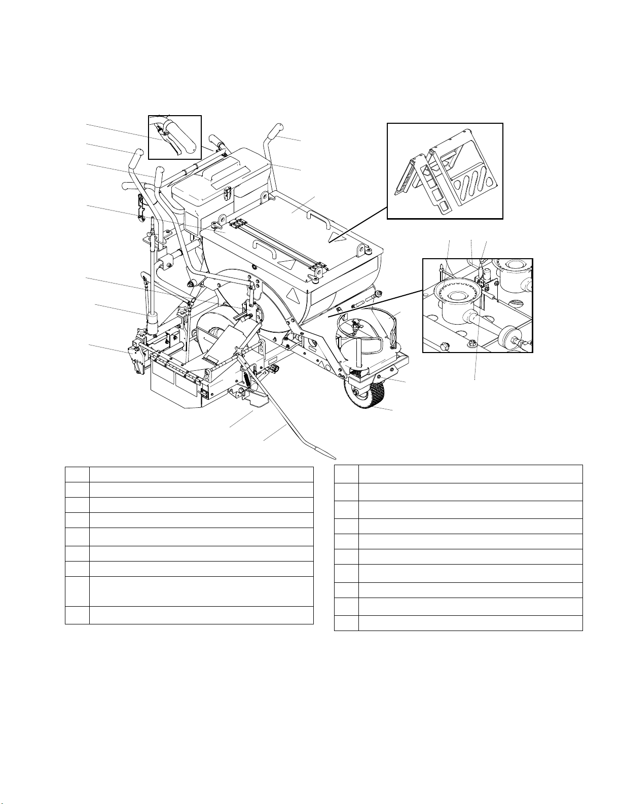
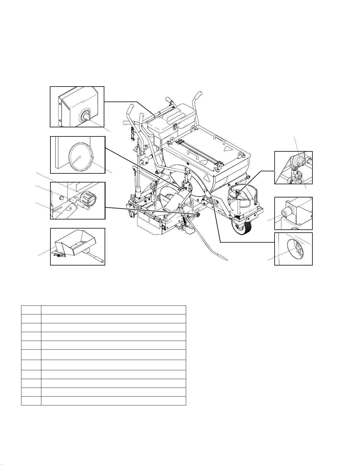
Component Identification
U
N
S
Y
R
AB
M
ti14145a
X
P
W
Z
A
L
C
J
U
V
T
K
H
A Kettle Main Burners
C Kettle Pilot Burner
H Line Guide
J LP Gas Cylinder Holder
K
SmartDie
L Kettle Thermopile
M Bead Dispenser Box
N
SmartDie
Actuator
P
SplitBead
*LP-Gas supply cylinder not supplied by Graco. LP-Gas supply cylinder must be designed, fabricated, and marked in
accordance with specifications and regulators for LP-Gas cylinders at The U.S. Department of Transportation (DOT),
The National Standard of Canada, CAN/CSA-B339, Cylinders, Spheres, and Tubes for Transportation of Dangerous
Goods, The Transportable Pressure Vessels Regulators 2001 (S1 2001/1426), The Gas Cylinders (Pattern Approval)
Regulations 1987 (SI 1987/116)(Pattern Approval Regulations) for EEC-type cylinders under European Directive
84/525/EEC, 84/526/EEC, and 84/527/EEC.
™
Lever
™
Screed Box/Bead Dispenser Box
™
Bead Hopper
R
ControlFlow
S
ControlFlow
T
SmoothRide
U Lock/Unlock for Swivel Wheel
V Kettle Pilot Ignitor Electrode
W Central Pour Access Cover with Latches
X
PaddleMax
Y Inspection Cover with Latches
Z
PaddleMax
AB Torch
™
Gate Valve
™
Gate Valve Actuator
™
Swivel Tire
™
Agitator Actuator
™
Agitator
313787C 5
Page 6
Component ID (Continued)
Component ID (Continued)
JJ
HH
GG
EE
AA
BB
LL
KK
DD
ti14146a
CC
Ref. Component
AA Kettle Temperature Control Knob
BB Kettle Temperature Indicator
CC Kettle Gas Safety Valve
DD Kettle Pilot Burner Ignitor
EE
GG
HH IR Burner Safety Shut-Off Valve with Thermocouple
JJ IR Burner Regulator/Flow Control Valve
KK Kettle Burners Manual Shut-Off Valve
LL Kettle Burner Regulator
6 313787C
SmartDie
SmartDie
™
Screed Box
™
Screed Box IR Burner
Page 7
Important Safety Information
If you do not follow these instructions exactly, a fire or
explosion may result causing property damage, personal injury or death.
Keep gas supply hose away from hot surfaces and
flames.
Use equipment in accordance with state and local ordinances with Storage, Handling and Transportation of
Liquid Petroleum Gases, ANSI/NFPA58 or CSA B149.1
If equipment has been in storage, check for insects and
insect nests on burners and Venturi tubes.
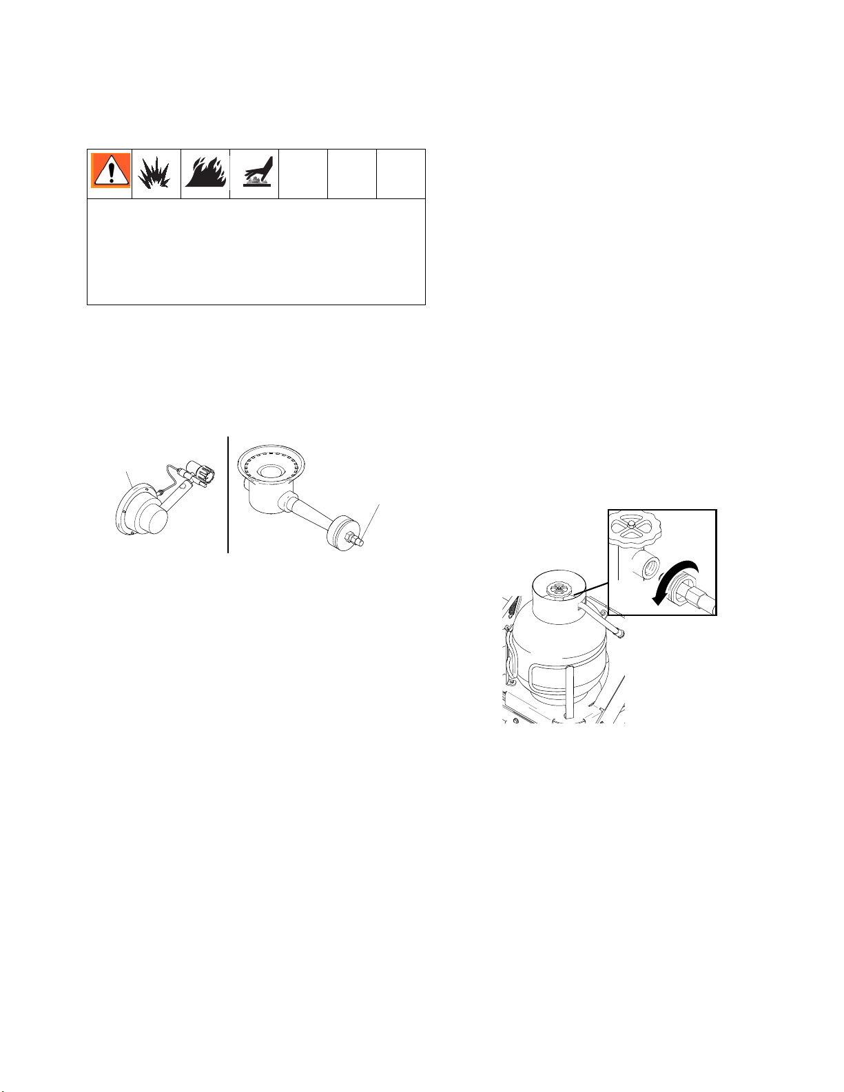
Burner
Venturi Opening
Important Safety Information
Use only vertical vapor-withdrawal LP gas cylinders
which have been designed, fabricated, tested and
marked in accordance with registration of the U.S.
Department of Transportation (DOT) or the Standard for
Cylinders, Spheres, and Tubes for the Transportation of
Dangerous Goods CAN/CSA-B337, The Transportable
Pressure Vessels Regulators 2001 (S1 2001/1426), The
Gas Cylinders (Pattern Approval) Regulations 1987 (SI
1987/116)(Pattern Approval Regulations) for EEC-type
cylinders (under European Directive 84/525/EEC,
84/526/EEC, and 84/527/EEC. Use only 20 lb to 30 lb
(9.07 kg to 13.6 kg) LP-Gas cylinders.
LP-Gas cylinder to be used only in vertical upright position as noted on agency approved LP-Gas cylinder for
proper vapor withdrawal.
Check gas supply hose connection to LP-Gas cylinder.
Make sure fitting is free of debris before connecting to
tank. Make sure gas connection is screwed completely
on and is free of leaks.
IR Burner
ti14156a
Kettle Burner
ti14411a
313787C 7
Page 8
Important Safety Information
Important Safety Information
If you do not follow these instructions exactly, a fire or
explosion may result causing property damage, personal injury or death.
BEFORE LIGHTING: Smell all around the working area
for gas. Be sure to smell next to the ground because
propane is heavier than air and will settle on the ground.
DAILY: Check for gas leaks. Use mild soap and water
solution or other approved method. Apply solution to all
gas lines and fittings then watch for gas bubbles.
WHAT TO DO IF YOU SMELL GAS OR FIND GAS
BUBBLES:
• Evacuate all unqualified personnel from area
• Do not try to light any burner
• Do not strike a flame
• Do not use electric fans to remove gas from area
• Do not touch any electric switch and do not use
any phone
• If leak is from a gas fitting, tighten fitting until leak
stops
• If leak is from a gas line, shut off at LP-gas cylinder and replace gas line
• Immediately call your gas supplier from a remote
phone. Follow gas supplier’s instructions.
• If leak can not be stopped by shutting off LP-gas
cylinder shut-off valve, immediately call your gas
supplier from a remote phone. Follow gas supplier’s instructions.
• If you cannot reach your gas supplier call the fire
department
ti14560a
ti14561a
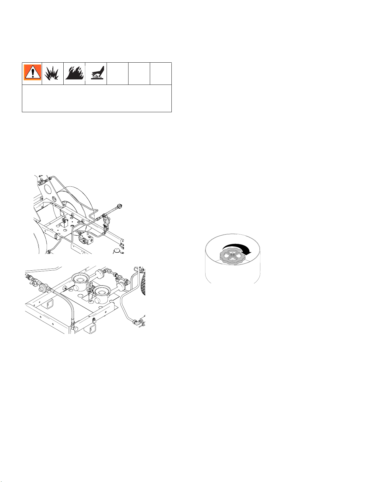
NOTE: Burners will need to be ignited to test gas lines
and fittings downstream of gas safety valves (CC and
HH). Ignite burners only after thoroughly checking gas
line and fitting upstream of gas safety valves.
ti14128a
Use only your hand to push in or turn the kettle gas
safety valve (CC). Never use tools. If the knob will not
push in or turn by hand, do not try to repair it; call a qualified service technician. Attempted repair or force may
result in a fire or explosion.
Do not use this equipment if any part has been under
water. Immediately call a qualified service technician to
inspect equipment and all components. Replace defective parts only with approved manufactured parts.
8 313787C
Page 9

Important Safety Information
Before attempting to start equipment:
If you do not follow these instructions exactly, a fire or
explosion may result causing property damage, personal injury or death.
All surfaces are capable of becoming extremely hot.
Be sure to always wear heat-resistant gloves and
other protective equipment rated for 500° F (260° C).
Material and unit are very hot 350° - 500° F
(177° C - 260° C). Never exceed 450° F (232° C)
material temperatures.
Hot molten plastic will burn skin. Do not attempt to
remove from skin. Cool under running water and
seek medical attention.
See MSDS for Thermoplastic Traffic Marking
Compound.
Important Safety Information
ti14409a
DAILY: Check all gas lines and fittings for gas leaks.
DAILY: Check gas supply hose for wear, abrasions, cuts
or leaks. Replace only with hoses recommended by
Graco.
Check gas supply hose connection to LP-gas cylinder.
Make sure fitting is free of debris before connecting to
tank. Make sure gas connection is screwed completely
on and is free of leaks.
Check to ensure that the following are closed:
• LP Gas Tank manual shut-off valve
• ControlFlow
™
gate valve
• Screed IR burner regulator/gas flow control valve
• Kettle gas burner manual shut-off valve
• Kettle gas safety valve
• Torch manual shut-off valve
• Kettle temperature control knob (turn to “OFF”)
• Torch gas flow control valve
If using Thermolazer™ in conjunction with Line-
™
Driver
, do not fill gasoline tank while burners are
ignited. Allow equipment to completely cool before
refueling.
Avoid prolonged inhalation of fumes.
Check to make sure exhaust openings on kettle are not
obstructed.
ti14412a
Check to make sure combustion air supply openings on
kettle are not obstructed.
ti14503a
Air Openings
313787C 9
Page 10

Lighting Instructions
Lighting Instructions
Lighting Kettle Burners
Read For Your Safety, page 7.
1. Turn temperature control knob (AA) to 0 (“OFF”).
AA
ti14124a
2. Turn kettle gas safety valve (CC) to “OFF”.
CC
ti14131a
6. Push in gas safety valve knob.
7. Push kettle pilot burner igniter (DD) until pilot
ignites.
8. Continue to push in gas safety valve (CC) in for
approximately 1 minute. If pilot goes out, repeat
steps 4-6 after 10 minutes.
If pilot ignites without depressing the gas safety valve
knob, replace gas safety valve. If gas safety valve
knob does not pop back after releasing in pilot position, STOP and replace gas safety valve. Shut off gas
at propane tank before replacing valve.
9. Turn gas safety valve knob to “ON”.
10. Turn temperature to 250° F (121° C) and observe
that main burners have ignited. Turn kettle temperature control back to “0” and observe that main burners shut off.
3. Open burner view port.
ti14130a
4. Open manual shut-off valve on propane tank
located at front of unit; open kettle manual shut-off
valve (KK) below kettle and behind propane tank.
ti14129a
ti14127a
5. Turn gas safety valve (CC) to “PILOT”.
DD
CC
ti14131a
KK
If main burners do not ignite or shut off when rotating
temperature control knob, STOP. Shut off gas at the
propane tank. Follow diagnostic procedure in Repair
manual.
11. Close burner view port.
12. Turn temperature control to desired setting.
Shutting Off Burner
1. Turn gas safety valve to “OFF”.
2. Close manual shut-off valve on propane tank. Close
kettle manual shut-off valve (KK) when finished
heating with kettle burners.
KK
ti14125a
ti14128a
NOTE: The kettle gas burner can be lit manually with a
small torch (for example: DOT 39 NRC 228/286 Cylinder
with #3 torch tip) if the battery powered pulse ignitor fails
to light the pilot.
10 313787C
Page 11

Torch Lighting Instructions
1. Open manual shut-off valve on propane tank
located at front of unit.
Lighting Instructions
Shutting Off Torch
1. Fully close torch flame adjusting valve.
ti14127a
2. Open torch manual shut-off valve next to torch regulator.
ti14137a
3. Remove external torch from holder.
ti14138a
ti14605a
2. Close torch manual shut-off valve when finished
heating with torch.
ti14602a
3. Close manual shut-off valve on propane tank when
finished heating with torch.
ti14128a
4. Slowly open torch flame adjusting valve and use
striker to ignite flame.
ti14141a
ti14139a
5. Adjust flame to desired length.
313787C 11
Page 12

Lighting Instructions
SmartDie™ Screed Box IR Burner
Lighting Instructions
Read Important Safety Information, page 7.
1. Open manual shut-off valve on propane tank
located at front of unit.
ti14127a
5. Place torch at end of IR burner next to stainless
steel mesh on burner.
ti14142a
6. Press in safety shut-off valve knob (HH).
2. Light torch (see Torch Lighting Instructions, page
11).
3. Turn gas flow control knob (JJ) to full-on (three
flames position).
JJ
ti14126b
4. Open screed box shroud access door.
HH
ti14143a
7. Hold in safety shut-off knob until burner ignites. The
burner will give off a bright glow once burner ignites.
Shutting Off Gas
1. Turn gas flow control knob to “OFF” (0 position).
2. Close manual shut-off valve on propane tank when
finished heating with screed box IR burner.
ti14128a
ti14140a
12 313787C
Page 13

SmartDie™ Screed Box
Installation
Use extreme caution when installing and removing
screed box. Expect all equipment components and
material to be extremely hot. See MSDS for Thermoplastic Traffic Marking Compound.
1. Shut off the SmartDie™ screed box IR burner.
SmartDie™ Screed Box
™
5. Engage SmartDie
screed box rod into SmartDie™
lever.
ti14268a
6. Align hole of rod clevis with connecting hole in
SmartDie
™
screed box yoke and install hairpin cot-
ter pin.
ti14126a
2. Open screed shroud door.
ti14140a
3. Move SmartDie
™
screed box actuator out of full
raised locked position.
ti14267a
4. Slide SmartDie
™
screed box under screed shroud
and press down on SmartDie
™
lever.
ti14155a
7. Close and lock screed shroud door.
8. Re-light SmartDie
™
screed box IR burner as
required.
Removal
1. Shut off SmartDie™ screed box IR burner.
ti14126a
2. Open screed shroud door.
ti14140a
ti14271a
313787C 13
Page 14

SmartDie™ Screed Box
3. Set SmartDie™ screed box on ground but not in
locked open position.
ti14267a
4. Remove hairpin cotter pin connecting SmartDie
screed box to rod clevis.
ti14155a
5. Press down SmartDie
™
lever.
™
1. Loosen two bolts on SmartDie
screed box mount-
ing bracket.
ti14504a
2. Slide mount down until leading box edge of Smart-
™
™
Die
screed box die runner is just off of the ground
surface. For best performance, raise leading edge
0 - 0.03 in. (0 - 0.076 cm) off ground surface.
ti14505a
SmartDie™ Screed Box Gate
SmartDie
™
Screed Box Trough
ti14270a
™
6. Disengage SmartDie
™
lever and carefully remove SmartDie™.
Die
screed box rod from Smart-
Adjustment
The height and angle of the SmartDie™ screed box can
be adjusted to ensure a solid line of material on any surface. For optimum delivery of thermoplastic material,
make sure the SmartDie
allel to road surface.
™
SmartDie
Screed Box Gate
™
screed box die runner is par-
SmartDie
™
Screed Box Trough
ti14414a
0 - 0.030 in.
™
SmartDie
Screed Box Die Runner
3. Tighten bolts on screed box mounting bracket.
ti14506a
ti14545a
SmartDie™ Screed Box Die Runner
14 313787C
Page 15

Replacing SmartDie™
Screed Box Spring
SmartDie™ Screed Box
1. Position replacement spring as shown below and
slide into spring guard.
ti14551a
2. Push spring up through guard and loop end around
guard pin until spring sits in groove.
ti14549a
3. Set SmartDie
™
screed box on its side.
4. Loop open end of spring and guard over first pin on
™
SmartDie
and over second pin on SmartDie
screed box. Then push spring guard up
™
screed box.
ti14550a
ti14552a
NOTE: Make sure spring end is fully engaged in groove
to prevent spring from coming loose.
Line Thickness Adjustment
To adjust the thickness of the line of material delivered
from the screed box, loosen all acorn nuts on the Smart-
™
Die
screed box gate and move the spacer until desired
line thickness is achieved.
ti14553a
ti14272a
ti14273a
Typical settings on pavement: 0.060 - 0.125 in.
(0.153 - 0.318 cm).
Typical settings on metal stencil: Flush - 0.0 in. (0.0 cm).
313787C 15
Page 16

Preparing ThermoLazer™ for Application
Preparing ThermoLazer™ for Application
Keep all access covers closed and latched when equipment is in use.
Always secure ThermoLazer
™
by chocking wheels
when adding thermoplastic.
1. Make sure kettle burners and SmartDie™ screed
box burner are lit.
2. Allow kettle to heat up before adding material. If kettle is completely empty, allow kettle to reach
300° - 350° F (149° - 177° C) before adding material. If kettle has material, allow material to reach
380° F (193° C) before adding material.
3. Secure ThermoLazer
™
by chocking wheels.
5. Move ControlFlow
™
Gate Valve Actuator (S) to
raised position and fill screed box with melted thermoplastic material.
S
ti14123a
0.5 in.
NOTE: The material gate is adjustable. The gate is
factory set at a 0.5 in. (1.3 cm) gap. You can
increase this gap for more material flow or decrease
the gap for less material flow.
6. Do not overfill material in kettle. Overfill would be
material higher than 5 in. (13 cm) below top of kettle.
5.0 in.
4. Add thermoplastic material to kettle.
ti14122a
ti14603a
Overfill
Line
ti14410a
7. Close and latch cover access doors when applying
thermoplastic.
8. Avoid bumping or impacting Thermolazer
™
to pre-
vent spillage or splashing of hot material.
16 313787C
Page 17

Bead Dispenser Box
Bead Dispenser Box
The Bead Dispenser Box has three doors which can be
opened and closed to allow beads to be dispensed at
desired width patterns.
ti14153a
ti14151a
ti14152a
Bead flow rate can be adjusted using the Bead Flow
Rate Lever on the outside of the Bead Dispenser Box.
ti14157a
Adding Beads to SplitBead™ Bead Hopper
Single Bead Application
1. Unlock and open SplitBead™ bead hopper door.
2. Fill both sides of hopper with beads.
3. Close and lock hopper door. Do not allow beads to
remain in hopper, hoses or bead dispenser for an
extended period of time. Beads will absorb moisture, bond to adjacent beads and harden.
Bead Dispenser Engagement Wheel
To properly dispense beads, drive wheel (27) must be in
direct contact with tire (89). If drive wheel (27) becomes
loose and/or starts to slip, use allen wrench to tighten
set screw (211).
Double Bead Application
(Requires Installation of Double Bead Kit 24C528)
1. Fill element beads on left side (smaller chamber).
2. Fill glass beads on right side (larger chamber).
3. Close and lock hopper door. Do not allow beads to
remain in hopper, hoses or bead dispenser for an
extended period of time. Beads will absorb moisture, bond to adjacent beads and harden.
Applying Material to a Surface
3. Pull thermoplastic ControlFlow
4. Open bead box gate and fill bead box dispenser to a
1. Position unit over target area and push Thermo-
™
Lazer
locks into centered position (a slight click will be
heard when wheel is engaged). Use Line Guide to
help orientate ThermoLazer
2. Pull unit back to start of target area and move
screed box into position.
forward in a straight line until front wheel
™
.
5. Push SmartDie
6. Push ThermoLazer
For examples of correct and incorrect material application, see Troubleshooting section in Repair manual.
211
89
27
™
Gate Valve Actua-
tor (S) and fill screed box with melted material.
level 1.5 in. (3.8 cm) from top.
™
screed box/bead dispenser box
actuator (N) lever forward to deploy screed box and
engage bead dispense wheel.
™
unit forward with screed box
deployed and bead dispenser wheel engaged to
apply material.
ti14564a
313787C 17
Page 18

Shutting Down
Shutting Down
1. Turn kettle gas safety valve (CC) to “OFF” position.
5. Turn torch gas flow valve to closed position.
ti14139a
ti14626a
2. Turn temperature control knob (AA) to 0 (“OFF”).
ti14124a
3. Turn screed burner regulator/flow control valve to “0”
(OFF).
ti14126a
6. Turn torch manual shut-off valve OFF.
7. Turn main gas valve on propane tank OFF.
ti14128a
Always store LP-Gas cylinder outside and in an
approved/secure storage locker.
4. Close kettle burner manual shut-off valve (KK)
below kettle and behind propane tank OFF.
ti14125a
18 313787C
Thermolazer
the LP-Gas cylinder has been removed.
™
can be stored inside a building ONLY IF
Page 19

Clean-Up
Never scoop out remaining melted thermoplastic from
kettle. Remaining thermoplastic can be left to harden
inside the kettle and can be remelted at a later date.
Always secure ThermoLazer
when adding thermoplastic.
1. Secure ThermoLazer™ by chocking wheels.
™
by chocking wheels
ti14603a
Clean-Up
NOTICE
Be sure to thoroughly clean all material on BlackMax
Screed Die bar of screed box and any open areas to
prevent material from freezing moving parts of screed
box. Always run all material out of each die before
removing. Scrape out all remaining material before it
sets within the die.
NOTICE
To prevent material from hardening and blocking flow,
scrape all excess material off of external surfaces after
each use, including the material trough.
NOTICE
When using hand torch to loosen material from screed
box, do not allow flames to come in contact with screed
box springs. Screed box springs will lose their temper
from flames and will not properly close screed box.
NOTICE
Remove any remaining beads in the bead hopper and
bead dispenser to prevent beads from clogging hopper
and dispenser.
™
2. Use scraper to clean out trough and screed box.
ti14529a
Transporting
Remove LP-Gas supply cylinder from ThermoLazer™
before transporting. Secure in an approved location and
method as authorized by local, state, federal, national,
and international agencies.
Always use the designated mounted lifting lugs when
lifting the Thermolazer
only use ANSI approved slings and equipment rated for
a minimum of 2000 lb. Always use ANSI approved
equipment for securing ThermoLazer to transporting
equipment.
™
. When lifting the Thermolazer™
313787C 19
Page 20

Maintenance
Maintenance
DAILY: Make sure kettle main burners (A) are burning
correctly. The flame should be 1 - 2 in. (2.5 - 5.0 cm)
high and blue/orange in color.
DAILY: Check gas lines and fittings for gas leaks. Use
soap and water mixture or LP-gas leak detector to
detect gas leaks.
DAILY: Check LP-gas supply hose for abrasions, cut or
wear. Make sure hose fitting and tank fitting are free of
debris before connecting.
DAILY: Make sure kettle gas safety valve (CC) rotates
freely. Make sure valve freely moves in and out at the
“PILOT” position.
DAILY: Make sure a good spark is being produced at
the kettle pilot burner by the kettle pilot igniter electrode.
Spark gap should be .17 - .20 in. (.43 - .50 cm).
.17 to .20 in.
1 to 2 in.
A
ti14520a
Venturi gap .20 in. (.50 cm)
DAILY: Make sure IR burner safety shut-off valve (HH)
moves freely in and out.
DAILY: Make sure LP-gas only flows to burner when
safety shut-off valve knob is pressed in.
DAILY: Make sure the IR burner face emits a bright
orange glow when at high fire; i.e. the “three flames”
position on the Regulator/Flow Control Valve (JJ).
DAILY: Grease SmartDie
™
screed box.
DAILY: Check screed box springs for foreign debris &
wear.
ti14519a
DAILY: Make sure kettle main burners (A) ignite when
heat is required and shut-off when heat is not required.
DAILY: Make sure kettle pilot burner (C) is burning correctly. The flame should be 2 - 3 in. (5.0 - 7.6 cm) high
and blue/orange in color.
2 to 3 in.
ti14413a
DAILY: Check bead box dispenser drive wheel (27) and
Thermolazer
™
tire (89) for foreign debris.
WEEKLY: Grease thermoplastic flow control gate valve
guides.
WEEKLY: Check tire pressures.
WEEKLY: Check screed box die bar carbide runners for
wear.
MONTHLY: Grease PaddleMax
™
agitator rod ball joint
ends.
20 313787C
Page 21

Maintenance
Fat Track™ Front Swivel Wheel
System
ANNUALLY: Tighten nut (86a) on screw under dust cap
(92) until spring washer bottoms out. Then back off the
nut 1/2 to 3/4 turns.
ANNUALLY: Tighten nut (82) on screw (90) until it
begins to compress spring washer (83). Then tighten an
additional 1/4 turn.
MONTHLY: Grease the wheel bearing.
PERIODICALLY: Check caster locking pin (86t) for
wear. If pin is worn out, there will be play in the caster
wheel. Reverse or replace the pin as needed.
PERIODICALLY: Check caster wheel alignment as necessary.
FatTrack™ Front Swivel Tire Alignment
Align front wheel as follows:
1. Loosen cap screw (86h).
86h
ti14527a
2. Rotate front wheel fork left or right, as necessary, to
straighten alignment.
3. Tighten cap screw (86h). Push striper and let striper
roll with hands off of striper.
NOTE: If striper rolls right or left, then repeat steps 1
and 3 until striper rolls straight.
313787C 21
Page 22

Technical Data
Technical Data
Fuel: Liquefied petroleum gas (LP-gas) (propane vapor)
Gas supply pressure (maximum): 250 psi (17.24 bar)
Kettle burner inlet pressure: 11 in. w.c. (2.7 kPa)
IR burner inlet pressure: 12 psi (.83 bar)
Torch inlet pressure: 18 psi (1.24 bar)
Kettle main burner heating capacity (maximum): Two (2) burners; each burner rated at 10,100 btu/hr (2.96 kW)
Kettle pilot burner heating capacity (maximum): 3800 btu/hr (1.11 kW)
IR burner heating capacity (maximum): 14,000 btu/hr (4.10 kW)
Torch heating capacity (maximum): 100,000 btu/hr (29.31 kW)
Kettle holding capacity (maximum): 300 lb (136 kg) (thermoplastic traffic marking compound materials)
Kettle Temperature (maximum): 450° F (232° C)
Kettle Temperature (operating): 380° - 420° F (193° - 216° C) 60 psi (4.14 bar)
Tire pressure (rear wheels): 60 psi (4.14 bar)
Tire pressure (swivel wheel): 45 psi (3.10 bar)
Battery (Kettle Pilot Burner Igniter): AA (1.5 V)
Bead Hopper Capacity (maximum): 80 lb (36.3 kg) Type II glass beads
Dimensions
Weight: 295 lb (134 kg)
Length: 72 in. (1.83 m)
Height: 51 in. (1.30 m)
Width: 48 in. (1.22 m)
22 313787C
Page 23

Notes
Notes
313787C 23
Page 24

Graco Standard Warranty
Graco warrants all equipment referenced in this document which is manufactured by Graco and bearing its name to be free from defects in
material and workmanship on the date of sale to the original purchaser for use. With the exception of any special, extended, or limited warranty
published by Graco, Graco will, for a period of twelve months from the date of sale, repair or replace any part of the equipment determined by
Graco to be defective. This warranty applies only when the equipment is installed, operated and maintained in accordance with Graco’s written
recommendations.
This warranty does not cover, and Graco shall not be liable for general wear and tear, or any malfunction, damage or wear caused by faulty
installation, misapplication, abrasion, corrosion, inadequate or improper maintenance, negligence, accident, tampering, or substitution of
non-Graco component parts. Nor shall Graco be liable for malfunction, damage or wear caused by the incompatibility of Graco equipment with
structures, accessories, equipment or materials not supplied by Graco, or the improper design, manufacture, installation, operation or
maintenance of structures, accessories, equipment or materials not supplied by Graco.
This warranty is conditioned upon the prepaid return of the equipment claimed to be defective to an authorized Graco distributor for verification of
the claimed defect. If the claimed defect is verified, Graco will repair or replace free of charge any defective parts. The equipment will be returned
to the original purchaser transportation prepaid. If inspection of the equipment does not disclose any defect in material or workmanship, repairs will
be made at a reasonable charge, which charges may include the costs of parts, labor, and transportation.
THIS WARRANTY IS EXCLUSIVE, AND IS IN LIEU OF ANY OTHER WARRANTIES, EXPRESS OR IMPLIED, INCLUDING BUT NOT LIMITED
TO WARRANTY OF MERCHANTABILITY OR WARRANTY OF FITNESS FOR A PARTICULAR PURPOSE.
Graco’s sole obligation and buyer’s sole remedy for any breach of warranty shall be as set forth above. The buyer agrees that no other remedy
(including, but not limited to, incidental or consequential damages for lost profits, lost sales, injury to person or property, or any other incidental or
consequential loss) shall be available. Any action for breach of warranty must be brought within two (2) years of the date of sale.
GRACO MAKES NO WARRANTY, AND DISCLAIMS ALL IMPLIED WARRANTIES OF MERCHANTABILITY AND FITNESS FOR A
PARTICULAR PURPOSE, IN CONNECTION WITH ACCESSORIES, EQUIPMENT, MATERIALS OR COMPONENTS SOLD BUT NOT
MANUFACTURED BY GRACO. These items sold, but not manufactured by Graco (such as electric motors, switches, hose, etc.), are subject to
the warranty, if any, of their manufacturer. Graco will provide purchaser with reasonable assistance in making any claim for breach of these
warranties.
In no event will Graco be liable for indirect, incidental, special or consequential damages resulting from Graco supplying equipment hereunder, or
the furnishing, performance, or use of any products or other goods sold hereto, whether due to a breach of contract, breach of warranty, the
negligence of Graco, or otherwise.
FOR GRACO CANADA CUSTOMERS
The Parties acknowledge that they have required that the present document, as well as all documents, notices and legal proceedings entered into,
given or instituted pursuant hereto or relating directly or indirectly hereto, be drawn up in English. Les parties reconnaissent avoir convenu que la
rédaction du présente document sera en Anglais, ainsi que tous documents, avis et procédures judiciaires exécutés, donnés ou intentés, à la suite
de ou en rapport, directement ou indirectement, avec les procédures concernées.
Graco Information
TO PLACE AN ORDER, contact your Graco distributor or call to identify the nearest distributor.
Toll Free: 1-800-690-2894.
All written and visual data contained in this document reflects the latest product information available at the time of publication.
Graco reserves the right to make changes at any time without notice.
Original instructions. This manual contains English. MM 313787
Graco Headquarters: Minneapolis
International Offices: Belgium, China, Japan, Korea
GRACO INC. P.O. BOX 1441 MINNEAPOLIS, MN 55440-1441
Copyright 2008, Graco Inc. is registered to ISO 9001
www.graco.com
Revised 10/2010
 Loading...