

Page 1
Repair-Parts
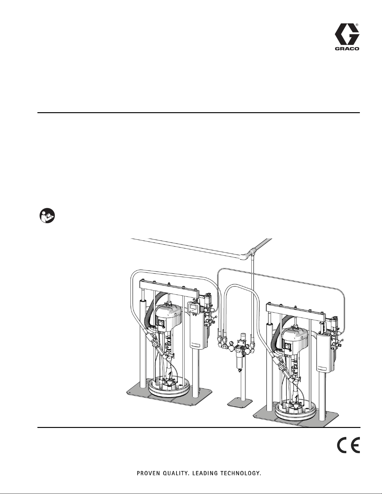
Tandem Supply
313529J
Systems
For use with non-heated bulk supply of medium to high viscosity sealants and adhesive
materials. For professional use only.
Not approved for use in European explosive atmosphere locations.
125 psi (0.9 MPa, 9 bar) Maximum Air Inlet Pressure - S20 3 in. rams
150 psi (1.0 MPa, 10 bar) Maximum Air Inlet Pressure - D60 and D200 3 in. rams
125 psi (0.9 MPa, 9 bar) Maximum Air Inlet Pressure - D200S 6.5 in. rams
Important Safety Instructions
Read all warnings and instructions in this manual.
Save these instructions.
EN
The Graco Control Architecture Electric Components are Listed in Intertek’s Directory of Listed Products.
D200 Rams with Electronic
Crossover Shown
TI10865A
Page 2

Contents
Related Manuals . . . . . . . . . . . . . . . . . . . . . . . . . . . 3
Models . . . . . . . . . . . . . . . . . . . . . . . . . . . . . . . . . . . 4
Warnings . . . . . . . . . . . . . . . . . . . . . . . . . . . . . . . . . 8
Troubleshooting . . . . . . . . . . . . . . . . . . . . . . . . . . . 10
Selector Switch . . . . . . . . . . . . . . . . . . . . . . . . . 12
Repair . . . . . . . . . . . . . . . . . . . . . . . . . . . . . . . . . . . 13
Pressure Relief Procedure . . . . . . . . . . . . . . . . 13
Ram Repair . . . . . . . . . . . . . . . . . . . . . . . . . . . . 13
Pump Repair . . . . . . . . . . . . . . . . . . . . . . . . . . . 13
Crossover Schematics . . . . . . . . . . . . . . . . . . . 13
Electronic Crossover Schematic . . . . . . . . . . . . . 14
Pneumatic Crossover Schematic . . . . . . . . . . . . . 15
Parts . . . . . . . . . . . . . . . . . . . . . . . . . . . . . . . . . . . . 17
Electronic Crossover Kits, with display . . . . . . . 19
Power Supply Detail . . . . . . . . . . . . . . . . . . . . . 22
Electronic Crossover Kits, without display . . . . . 23
Pneumatic Crossover Kits . . . . . . . . . . . . . . . . . 25
Pneumatic Crossover Kits (continued) . . . . . . . 26
Fluid Filter Kit . . . . . . . . . . . . . . . . . . . . . . . . . . 28
Pump Outlet Check Valve Kits . . . . . . . . . . . . . 29
Depressurization Kits . . . . . . . . . . . . . . . . . . . . 30
Accessories . . . . . . . . . . . . . . . . . . . . . . . . . . . . . . 32
Communications Gateway Module . . . . . . . . . . 32
Pressure Sensor Accessories . . . . . . . . . . . . . . 32
Technical Data . . . . . . . . . . . . . . . . . . . . . . . . . . . . 33
Graco Standard Warranty . . . . . . . . . . . . . . . . . . . 34
Graco Information . . . . . . . . . . . . . . . . . . . . . . . . 34
2 313529J
Page 3

Related Manuals
Component Manuals in U.S. English:
Manual Description
313528 Tandem Supply Systems Operation
313526 Supply Systems Operation
313527 Supply Systems Repair-Parts
Check-Mate
312375
Instructions-Parts
Check-Mate
312376
Instruction-Parts
Dura-Flo
311827
180cc, 220cc, 290cc) Instructions-Parts
Manual
311825
311717
Dura-Flo
580cc) Instructions-Parts Manual
Carbon Steel Displacement Pump
(1000cc) Instructions-Parts Manual
Dura-Flo
311828
180cc, 220cc, 290cc) Instructions-Parts
Manual
311826
311833
312889
312467
312468
312469
312470
311238
312796
Dura-Flo
580cc) Instructions-Parts Manual
Two-Ball NXT
Instructions-Parts Manual
60 cc Check-Mate Displacement Pump
Repair Parts Manual
100 cc Check-Mate Displacement Pump
Repair Parts Manual
200 cc Check-Mate Displacement Pump
Repair Parts Manual
250 cc Check-Mate Displacement Pump
Repair Parts Manual
500 cc Check-Mate Displacement Pump
Repair Parts Manual
™
NXT
Instructions-Parts
™
NXT
Instructions-Parts
308213 Premier
312374 Air Controls Instructions-Parts
312491 Pump Fluid Purge Kit
®
Displacement Pumps
®
Pump Packages
™
Displacement Pumps (145cc,
™
Displacement Pumps (430cc,
™
Pump Packages (145cc,
™
Pump Packages (430cc,
™
Pump Packages (1000cc)
Air Motor (Nxxxxx models)
Air Motor (Mxxxxx models)
®
Air Motor Instructions-Parts
Related Manuals
312492 Drum Roller Kit Instruction
312493 Light Tower Kit Instruction
312864
313138
Communications Gateway Module,
Instructions-Parts
Supply System Communications Gateway
Module Installation Kit, Instructions-Parts
406681 Platen Cover Kit
313529J 3
Page 4
Models
Models
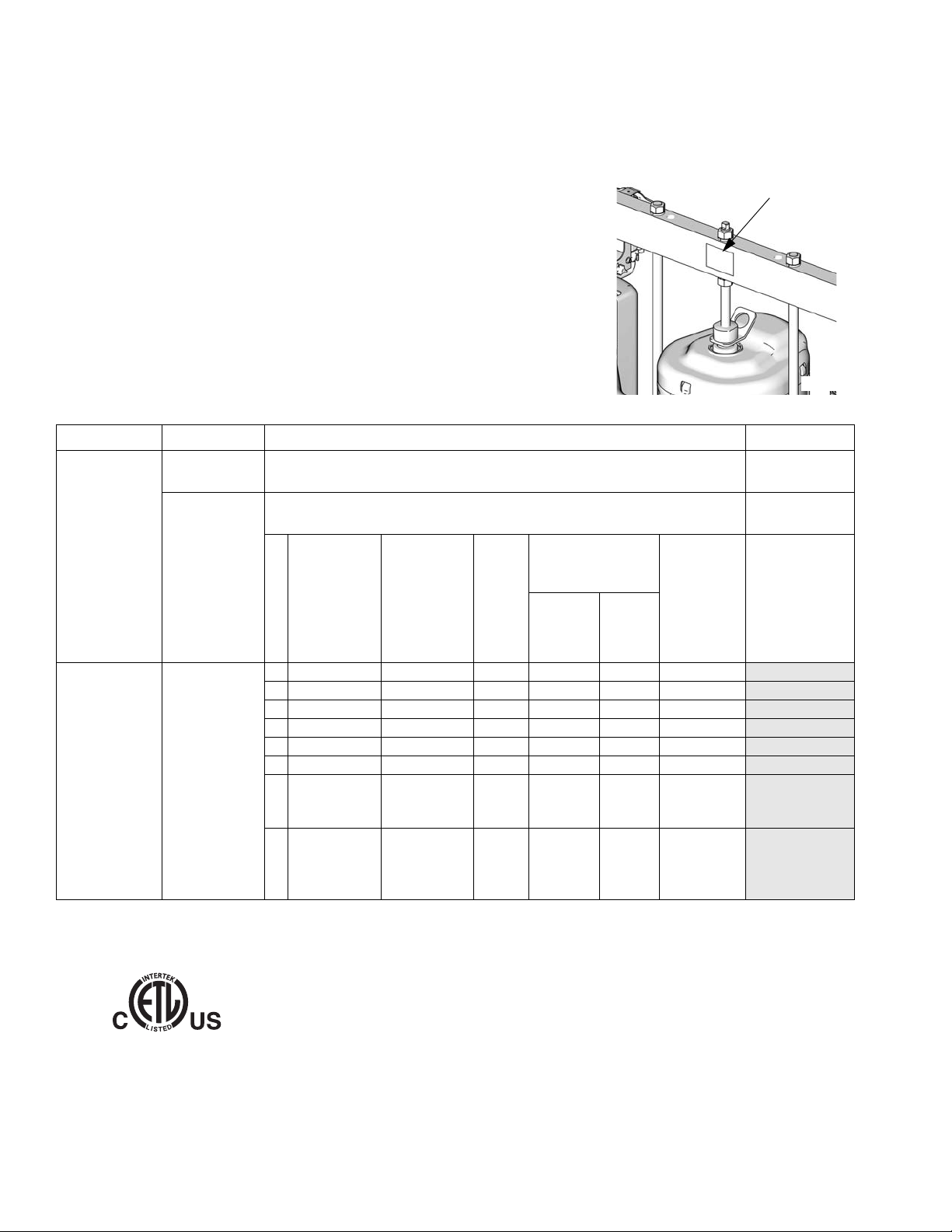
Check the identification plate (ID) for the 6-digit part number of your tandem system. Use the following matrix to define the construction of your system, based on
the six digits. For example, Tandem Part No. TC2414 represents a Check-Mate
tandem system (TC), pump (24), crossover option (1), and platen/ram option (4).
NOTE:
Systems with the TD as the first and second digits are Dura-Flo tandem systems.
Some configurations in the following matrix cannot be built. See the Product
Selection Guide for available systems.
To order replacement parts, see on page 16. The digits in the matrix do not correspond to the Ref. Nos. in the Parts drawings and lists.
TC 24 1 4
First and
Second Digit
TC
(Tandem
System with
Check-Mate
displacement
pump)
TD
(Tandem
System with
Dura-Flo dis-
placement
pump)
Third and
Fourth Digit Fifth Digit Sixth Digit
Crossover Options
Depressurize/
Recirculate Valve
Material
Carbon
Steel SST
Ram Size
n/a
n/a
n/a
n/a
n/a
n/a
S20, D60,
Pump Code
(See Table 2
for 2-digit
Check-Mate
pump code)
Electronic
Crossover
1
2
3
4
5
6
7
Pneumatic
Crossover
(Smart
Motors
only)
✔
(Standard
Motors
only)
Fluid
Filter
✔✔
✔✔✔
✔✔
✔✔
✔✔
✔
✔
D200,
(See Table 3
for 2-digit
Dura-
8
✔
(3 in.)
D200S,
(6.5 in.)
Flo pump
code)
ID
TI11157A
Platen/Ram
Options
See Table 1
for Selections
All supply systems with DataTrak and 24 Vdc or 100-240 Vac power supplies are ETL approved.
2ECOGNIZED#OMPONENT
#-
#ERTIFIEDTO#!.#3!#3!#.O
4 313529J
#ONFORMSTO5,
Page 5

Table 1: Platen/Ram Options
Models
Sixth
Digit Platen Size Platen Style
Platen
Material
Seal Material Ram Size Voltage
2 20 L (5 Gal) Flat, Single Wiper CS Polyurethane S20, 3 in. none
3 20 L (5 Gal) Flat, Single Wiper SST PTFE-Coated Nitrile S20, 3 in none
7 20 L (5 Gal) Flat, Dual Wiper CS Polyurethane D60, 3 in. none
8 20 L (5 Gal) Flat, Dual Wiper CS Polyurethane D60, 3 in. 120 Vdc
9 20 L (5 Gal) Flat, Dual Wiper CS Polyurethane D60, 3 in. 24 Vdc
0 30 L (8 Gal) Flat, Single Wiper SST PTFE-Coated Nitrile D60, 3 in. none
D 30 L (8 Gal) Flat, Single Wiper SST PTFE-Coated Nitrile D60, 3 in. 120 Vdc
E 30 L (8 Gal) Flat, Single Wiper SST PTFE-Coated Nitrile D60, 3 in. 24 Vdc
K 30 L (8 Gal) Flat, Dual Wiper CS Polyurethane D60, 3 in. none
N 30 L (8 Gal) Flat, Dual Wiper CS Polyurethane D60, 3 in. 120 Vdc
P 30 L (8 Gal) Flat, Dual Wiper CS Polyurethane D60, 3 in. 24 Vdc
U 60 L (16 Gal) Flat, Single Wiper SST PTFE-Coated Nitrile D60, 3 in. none
V 60 L (16 Gal) Flat, Single Wiper SST PTFE-Coated Nitrile D60, 3 in. 120 Vdc
W 60 L (16 Gal) Flat, Single Wiper SST PTFE-Coated Nitrile D60, 3 in. 24 Vdc
X 60 L (16 Gal) Flat, Dual Wiper CS Polyurethane D60, 3 in. none
Y 60 L (16 Gal) Flat, Dual Wiper CS Polyurethane D60, 3 in. 120 Vdc
Z 60 L (16 Gal) Flat, Dual Wiper CS Polyurethane D60, 3 in. 24 Vdc
4 115L (30 Gal) D Style CS EPDM D200, 3 in. none
1 20 L (5 Gal) Flat, Single Wiper SST PTFE-Coated Nitrile D200, 3 in. none
6 20 L (5 Gal) Flat, Dual Wiper CS Polyurethane D200, 3 in none
A 200 L (55 Gal) Dual O-ring AL PTFE-Coated EPDM D200, 3 in. none
B 200 L (55 Gal) Dual O-ring AL PTFE-Coated EPDM D200, 3 in. 120 Vdc
C 200 L (55 Gal) Dual O-ring AL PTFE-Coated EPDM D200, 3 in. 24 Vdc
F 200 L (55 Gal) Dual O-ring AL PTFE-Coated EPDM D200S, 6.5 in. none
G 200 L (55 Gal) Dual O-ring AL PTFE-Coated EPDM D200S, 6.5 in. 120 Vdc
H 200 L (55 Gal) Dual O-ring AL PTFE-Coated EPDM D200S, 6.5 in. 24 Vdc
J 200 L (55 Gal) Dual O-ring AL EPDM D200, 3 in. none
L 200 L (55 Gal) Dual O-ring AL EPDM D200, 3 in. 120 Vdc
M 200 L (55 Gal) Dual O-ring AL EPDM D200, 3 in. 24 Vdc
R 200 L (55 Gal) Dual O-ring AL EPDM D200S, 6.5 in. none
S 200 L (55 Gal) Dual O-ring AL EPDM D200S, 6.5 in. 120 Vdc
T 200 L (55 Gal) Dual O-ring AL EPDM D200S, 6.5 in. 24 Vdc
313529J 5
Page 6

Models
Table 2: Check-Mate Pump Identification Code/Part No. Index
Pump Part No.
Pump
Code
(see manual
312376)
NXT 200/CM 60
4A P05LCS
4B P05LCM
4C P05LSS
4F P05LSM
NXT 400/CM 60
6A P11LCS
6B P11LCM
6C P11LSS
6F P11LSM
6G P11RCS
6H P11RCM
6J P11RSS
6K P11RSM
61 P11SCS
62 P11SCM
63 P11SSS
64 P11SSM
NXT 700/CM 60
7A P20LCS
7B P20LCM
7C P20LSS
7F P20LSM
7G P20RCS
7H P20RCM
7J P20RSS
7K P20RSM
71 P20SCS
72 P20SCM
73 P20SSS
74 P20SSM
NXT 1200/CM 60
8A P38LCS
8B P38LCM
8C P38LSS
8F P38LSM
8G P38RCS
8H P38RCM
8J P38RSS
8K P38RSM
Pump Part No.
Pump
Code
(see manual
312376)
81 P38SCS
82 P38SCM
83 P38SSS
84 P38SSM
NXT 1800/CM 60
9A P61LCS
9B P61LCM
9C P61LSS
9F P61LSM
9G P61RCS
9H P61RCM
9J P61RSS
9K P61RSM
91 P61SCS
92 P61SCM
93 P61SSS
94 P61SSM
NXT 2200/CM 100
11 P40LCS
12 P40LCM
1F P40LSS
1G P40LSM
13 P40RCS
14 P40RCM
1H P40RSS
1J P40RSM
10 P40SSS
1A P40SSM
19 P40SCS
NXT 3400/CM 100
15 P63LCS
16 P63LCM
1T P63LSS
1U P63LSM
17 P63RCS
18 P63RCM
1W P63RSS
1Y P63RSM
1B P63SSS
1C P63SSM
Pump Part No.
Pump
Code
(see manual
312376)
NXT 2200/CM 200
21 P23LCS
22 P23LCM
23 P23RCS
24 P23RCM
25 P23LSS
26 P23LSM
27 P23RSS
28 P23RSM
NXT 3400/CM 200
29 P36LCS
2A P36LCM
2B P36RCS
2C P36RCM
2F P36LSS
2G P36LSM
2H P36RSS
2J P36RSM
NXT 6500/CM 200
2L P68LCS
2M P68LCM
2R P68RCS
2S P68RCM
2T P68LSS
2U P68LSM
2W P68RSS
2Y P68RSM
20 P68SCS
NXT 3400/CM 250
31 P29LCS
32 P29LCM
33 P29RCS
34 P29RCM
35 P29LSS
36 P29LSM
37 P29RSS
38 P29RSM
Pump Part No.
Pump
Code
(see manual
312376)
NXT 6500/CM 250
39 P55LCS
3A P55LCM
3B P55RCS
3C P55RCM
3F P55LSS
3G P55LSM
3H P55RSS
3J P55RSM
Premier/CM 250
3L P82LCS
3M P82LCM
3R P82LSS
3S P82LSM
NXT 3400/CM 500
51 P14LCS
52 P14LCM
53 P14RCS
54 P14RCM
55 P14LSS
56 P14LSM
57 P14RSS
58 P14RSM
NXT 6500/CM 500
59 P26LCS
5A P26LCM
5B P26RCS
5C P26RCM
5F P26LSS
5G P26LSM
5H P26RSS
5J P26RSM
Premier/CM 500
5L P39LCS
5M P39LCM
5R P39LSS
5S P39LSM
No Pump
NN
6 313529J
Page 7

Table 3: Dura-Flo Pump Identification Code/Part No. Index
Models
Pump Part No.
Pump
Code
(see manual
311828)
NXT 2200/DF 145SS
A1 P31LSS
A2 P31LSM
A3 P31HSS
A4 P31HSM
NXT 3400/DF 145SS
B1 P46LSS
B2 P46LSM
B3 P46HSS
B4 P46HSM
NXT 3400/DF 180SS
B5 P41LSS
B6 P41LSM
B7 P41HSS
B8 P41HSM
NXT 3400/DF 220SS
C1 P30LSS
C2 P30LSM
C3 P30HSS
C4 P30HSM
NXT 6500/DF 220SS
CA P57LSS
CB P57LSM
CC P57HSS
CD P57HSM
NXT 6500/DF 290SS
D1 P45LSS
D2 P45LSM
D3 P45HSS
D4 P45HSM
Premier/DF 290SS
DL P67LSS
DM P67LSM
DR P67HSS
DS P67HSM
Pump Part No.
Pump
Code
(see manual
311826)
NXT 3400/DF 430CS
E1 P15LCS
E2 P15LCM
E3 P15HCS
E4 P15HCM
NXT 3400/DF 430SS
E5 P15LSS
E6 P15LSM
E7 P15HSS
E8 P15HSM
NXT 6500/DF 430CS
E9 P32LCS
EA P32LCM
EB P32HCS
EC P32HCM
NXT 6500/DF 430SS
EF P32LSS
EG P32LSM
EH P32HSS
EJ P32HSM
Premier/DF 430
EL P44LSS
EM P44LSM
ER P44LCS
ES P44LCM
NXT 3400/DF 580CS
F1 P12LCS
F2 P12LCM
F3 P12HCS
F4 P12HCM
NXT 3400/DF 580SS
F5 P12LSS
F6 P12LSM
F7 P12HSS
F8 P12HSM
Pump Part No.
Pump
Code
(see manual
311826)
NXT 6500/DF 580CS
F9 P22LCS
FA P22LCM
FB P22HCS
FC P22HCM
NXT 6500/DF 580SS
FF P22LSS
FG P22LSM
FH P22HSS
FJ P22HSM
Premier/DF 580CS
FL P34LSS
FM P34LSM
FR P34LCS
FS P34LCM
Pump Part No.
Pump
Code
(see manual
311833)
NXT 3400/DF 1000CS
G1 P06LCS
G2 P06LCM
G3 P06HCS
G4 P06HCM
NXT 3400/DF 1000SS
G5 P06LSS
G6 P06LSM
G7 P06HSS
G8 P06HSM
NXT 6500/DF 1000CS
G9 P10LCS
GA P10LCM
GB P10HCS
0C P10HCM
NXT 6500/DF 1000SS
GF P10LSS
GG P10LSM
GH P10HSS
GJ P10HSM
Premier/DF 1000
GL NR
GM NR
GR NR
GS NR
NR = Not released
313529J 7
Page 8
Warnings
Warnings
The following warnings are for the setup, use, grounding, maintenance, and repair of this equipment. The exclamation point symbol alerts you to a general warning and the hazard symbol refers to procedure-specific risk. Refer back
to these warnings. Additional, product-specific warnings may be found throughout the body of this manual where
applicable.
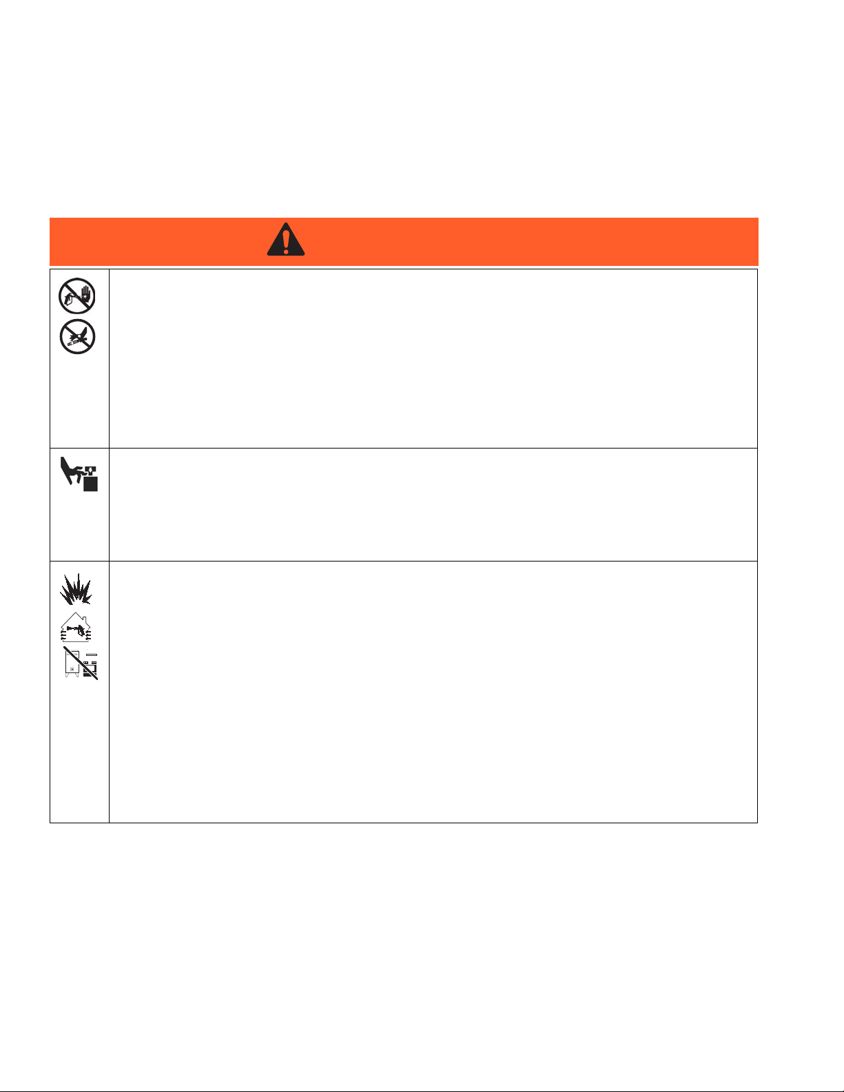
WARNING
SKIN INJECTION HAZARD
High-pressure fluid from gun, hose leaks, or ruptured components will pierce skin. This may look like just
a cut, but it is a serious injury that can result in amputation. Get immediate surgical treatment.
• Do not point gun at anyone or at any part of the body.
• Do not put your hand over the spray tip.
• Do not stop or deflect leaks with your hand, body, glove, or rag.
• Do not spray without tip guard and trigger guard installed.
• Engage trigger lock when not spraying.
• Follow Pressure Relief Procedure in this manual, when you stop spraying and before cleaning,
checking, or servicing equipment.
MOVING PARTS HAZARD
Moving parts can pinch or amputate fingers and other body parts.
• Keep clear of moving parts.
• Do not operate equipment with protective guards or covers removed.
• Pressurized equipment can start without warning. Before checking, moving, or servicing equipment,
follow the Pressure Relief Procedure in this manual. Disconnect power or air supply.
FIRE AND EXPLOSION HAZARD
Flammable fumes, such as solvent and paint fumes, in work area can ignite or explode. To help prevent
fire and explosion:
• Use equipment only in well ventilated area.
• Eliminate all ignition sources; such as pilot lights, cigarettes, portable electric lamps, and plastic drop
cloths (potential static arc).
• Keep work area free of debris, including solvent, rags and gasoline.
• Do not plug or unplug power cords, or turn power or light switches on or off when flammable fumes
are present.
• Ground all equipment in the work area. See Grounding instructions.
• Use only grounded hoses.
• Hold gun firmly to side of grounded pail when triggering into pail.
• If there is static sparking or you feel a shock, stop operation immediately. Do not use equipment
until you identify and correct the problem.
• Keep a working fire extinguisher in the work area.
8 313529J
Page 9
Warnings
WARNING
WARNINGWARNINGWARNING
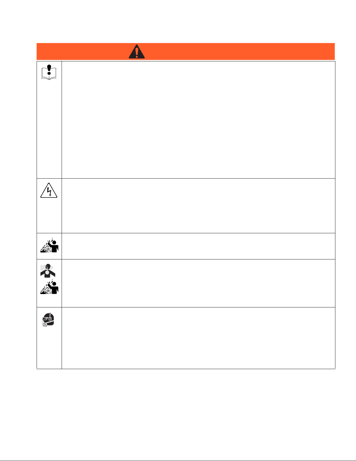
EQUIPMENT MISUSE HAZARD
Misuse can cause death or serious injury.
• Do not operate the unit when fatigued or under the influence of drugs or alcohol.
• Do not exceed the maximum working pressure or temperature rating of the lowest rated system
component. See Technical Data in all equipment manuals.
• Use fluids and solvents that are compatible with equipment wetted parts. See Technical Data in all
equipment manuals. Read fluid and solvent manufacturer’s warnings. For complete information
about your material, request MSDS forms from distributor or retailer.
• Check equipment daily. Repair or replace worn or damaged parts immediately with genuine manufacturer’s replacement parts only.
• Do not alter or modify equipment.
• Use equipment only for its intended purpose. Call your distributor for information.
• Route hoses and cables away from traffic areas, sharp edges, moving parts, and hot surfaces.
• Do not kink or over bend hoses or use hoses to pull equipment.
• Keep children and animals away from work area.
• Comply with all applicable safety regulations.
ELECTRIC SHOCK HAZARD
Improper grounding, setup, or usage of the system can cause electric shock.
• Turn off and disconnect power cord before servicing equipment.
• Use only grounded electrical outlets.
• Use only 3-wire extension cords.
• Ensure ground prongs are intact on sprayer and extension cords.
• Do not expose to rain. Store indoors.
SPLATTER HAZARD
During blowoff of platen splatter may occur.
• Use minimum drum removal air pressure.
TOXIC FLUID OR FUMES HAZARD
Toxic fluids or fumes can cause serious injury or death if splashed in the eyes or on skin, inhaled, or
swallowed.
• Read MSDS’s to know the specific hazards of the fluids you are using.
• Store hazardous fluid in approved containers, and dispose of it according to applicable guidelines.
• Always wear impervious gloves when spraying or cleaning equipment.
PERSONAL PROTECTIVE EQUIPMENT
You must wear appropriate protective equipment when operating, servicing, or when in the operating
area of the equipment to help protect you from serious injury, including eye injury, inhalation of toxic
fumes, burns, and hearing loss. This equipment includes but is not limited to:
• Protective eyewear
• Clothing and respirator as recommended by the fluid and solvent manufacturer
•Gloves
• Hearing protection
313529J 9
Page 10
Troubleshooting
Troubleshooting
NOTE: Refer to the Supply System Repair-Parts
manual for specific ram troubleshooting. Refer to
the Check-Mate Pump Packages manual for pump
troubleshooting.
Problem Cause Verification Solution
No power. Customer supplied main
circuit breaker tripped.
No graphics on screen. No graphics are shown on
display screen.
1. Follow Pressure Relief Procedure, page 13, before
disassembling any part of the supply system.
2. Disconnect power before repairing the supply system.
3. Check all possible problems and causes before disassembling the supply system.
Measure voltage across
disconnect switch; voltage
should measure between
190 and 250 Vac.
Verify green LED on bottom
of display is illuminated.
Determine cause of the
tripped circuit breaker.
Then repair fault and reset
main circuit breaker.
If green LED is not illuminated:
Backlight does not power
up.
Can see display, but backlight is not illuminated when
a button is pressed.
1. Check for DC power at
display. Replace faulty
cable/component.
2. Replace faulty display
module.
If green LED is illuminated,
check red LED. If red LED
is illuminated, replace display module.
Replace display module.
10 313529J
Page 11

Problem Cause Verification Solution
Missing module. Modules not on network. Verify attached modules
through Advanced Setup
screens 4 and 5.
Cable disconnected. Verify all green LEDs are
illuminated and yellow
LEDs are flashing.
Module with wrong selector switch setting.
Verify selector switch is set
correctly.
Troubleshooting
Enter Setup screen and
scroll to Advanced Setup
screens 4 and 5. These
screens lists all components corresponding software revision number on
network.
Reconnect/replace faulty
cable.
1. Remove power from
unit.
2. Remove access cover
and visually check
rotary switch setting.
3. If incorrect, set to correct setting. See Selec-
tor Switch, page 12,
for selector switch locations.
Does not crossover. Alternate ram has an empty
sensor activated.
Alternate pump is not
primed.
Alternate pump has an
active alarm.
4. Replace access cover.
Verify ram has material. Replace empty drum.
Verify alternate ram is
Prime pump.
ready to run.
See Alarm Codes and
Troubleshooting in the
Tandem Supply Systems
Operation manual.
See Alarm Codes and
Troubleshooting in the
Tandem Supply Systems
Operation manual.
313529J 11
Page 12

Troubleshooting
Selector Switch
Ensure the selector switch (inside the fluid control module) is set correctly for each ram.
1. Turn power off.
2. Remove access cover (D).
D
TI12334a
F
IG. 1:
3. For ram A, ensure the selector switch (S) is set to
“A”. If it is not, use a flat head screwdriver to adjust
the switch to “A”.
4. For ram B, ensure the selector switch (S) is set to
“B”. If it is not, use a flat head screwdriver to adjust
the switch to “B”.
S
F
IG. 2:
5. Replace access cover.
6. Turn power on.
12 313529J
Page 13

Repair
Pressure Relief Procedure
1. Lock the gun/valve trigger.
Repair
BF
2. Press On/Off key . If system is On, display will
highlight . Select to turn off.
FIG. 3: System Function Screen
3. Turn off the air motor slider valve (BF) on both ram A
and B.
4. On both ram A and B, turn off the main air slider
valve (BA). Set the ram director valve (BC) to the
down position. The ram will slowly drop.
5. Unlock the gun/valve trigger.
BE
BG
BC
BB
BA
TI10438A
FIG. 4. Integrated Air Controls
Ram Repair
See manual 313527 for ram and platen repair procedures and replacement parts.
6. Hold a metal part of the gun/valve firmly to the side
of a grounded metal pail, and trigger the gun/valve
to relieve pressure.
7. Lock the gun/valve trigger.
8. On both ram A and B, open the drain valve and/or
the pump bleed port. Have a container ready to
catch the drainage.
If you suspect that the spray tip/nozzle or hose is completely clogged, or that pressure has not been fully
relieved after following the steps above, very slowly
loosen the tip guard retaining nut or hose end coupling
and relieve pressure gradually, then loosen completely.
Now clear the tip/nozzle or hose.
313529J 13
Pump Repair
See pump manuals for pump repair procedures and
replacement parts.
See manual 311238 (Nxxxxx NXT models), 312796
(Mxxxxx NXT models), or 308213 (Premier) for air motor
repair procedures and replacement parts.
Crossover Schematics
See page 14 for a schematic of electronic crossover
systems and page 15 for a schematic of pneumatic
crossover systems.
Page 14

Electronic Crossover Schematic
Electronic Crossover Schematic
Fluid Solenoid
(1) Signal
(2) Common
(GND) Unused
Graco P/N 15M574
F
(1)
(2)
(3)
Wire Harness
Graco P/N 15Y047
M
(1)
(2)
(3)
(4)
3
Drain (2)
Signal (4)
Unused (1)
Common (3)
FLUID
RAM B
MODULE
CONTROL
5
(2) N/C
(3) Motor Reed Up
(5) Motor Reed Com
(7) Linear Com
(1) Linear Input
(4) Motor Reed Down
(6) Linear Power
M
(8) Drain
(1)
(2)
(3)
(4)
(5)
(6)
(7)
(8)
DRUM LOW
Graco P/N 122716
Cable Splitter
Graco P/N 15X968
DRUM EMPTY
(2) Unused
(1) Power
(1)
(3)
(2)
M
1
(3) COM
(2) Unused
(1) Power
(4) SIGNAL
(3) COM
Graco P/N 122716
F
(1)
(3)
(4)
(2)
(4) SIGNAL
(4)
(5)
(1)
(2)
(3)
(4)
Power (1)
Common (3)
Air Solenoid (5)
Low Sensor (2)
Empty Sensor (4)
(1) Solenoid signal
(2) Solenoid RTN
F
(1)
(2)
AIR SOLENOID
Graco P/N 121235
SHLD (1)
SHLD (1)
-24Vdc (3)
+24Vdc (2)
-24Vdc (3)
+24Vdc (2)
CAN_L (5)
CAN_H (4)
CAN_H (4)
CAN_L (5)
Motor Pigtail
Graco P/N 15X619
M
(1)
FLUID
CONTROL
Motor Pigtail
Graco P/N 15X619
M
(1)
(2)
(2)
(3)
(4)
RAM A
MODULE
(3)
(4)
(5)
Cable 8 Pin
Graco P/N 15Y051
FM
(5)
5
(1) Linear Input
M
(1)
Cable 8 Pin
Graco P/N 15Y051
F
M
Sensor Reed Switch
(1)
(2)
(3)
(4)
(1)
(2)
(3)
(4)
MF
(1)
(2)
(3)
(1)
(2)
(3)
Top Switch (1)
Top Switch (2)
Graco P/N 119700
Bottom Switch (1)
Sensor Reed Switch
(4) Motor Reed Down
(6) Linear Power
(2) N/C
(3) Motor Reed Up
(5) Motor Reed Com
(2)
(3)
(4)
(5)
(6)
(1)
(2)
(3)
(4)
(5)
(6)
(1)
(2)
(3)
(4)
(5)
(6)
(1)
(2)
(3)
(4)
MF
(1)
(2)
(3)
(4)
Top Switch 1
Top Switch 2
Bottom Switch 1
Bottom Switch 2
Graco P/N 119700
(5)
(6)
(7)
(8)
(5)
(6)
(7)
(8)
(4)
(4)
Bottom Switch (2)
(8) Drain
(7) Linear Com
(7)
(8)
(7)
(8)
(7)
(8)
Cable Splitter
Graco P/N 15Y037
(1)
(2)
(3)
7
M
Cable 15 Meter
MF
(4)
(4) Filter Outlet Press.
(5) Drain
(1) Power
(2) Filter Inlet Press.
(3) Common
(5)
(1)
(2)
(3)
(4)
Graco P/N 15Y048
(1)
(2)
(3)
(4)
(1)
(2)
(3)
(4)
(5) (5)
(1)
Ferrite Bead
Graco P/N 121901
Depressurization
Accessory Kit
DRUM EMPTY
(1) Power
(4) SIGNAL
(3) COM
(2) Unused
Graco P/N 122716
F
(1)
(3)
(4)
(2)
Light Tower
(1) Unused
(2) Amber
(3) Common
(4) Green
(1) Signal
(2) Common
(GND) Unused
Fluid Solenoid
Graco P/N 15M574
F
(1)
(2)
(3)
Ferrite Bead
Wire Harness
Graco P/N 121901
Graco P/N 15Y047
M
(1)
(2)
(3)
(4)
3
Drain (2)
Signal (4)
Unused (1)
Common (3)
DISPLAY
MODULE
(2)
(3)
(4)
Graco P/N 15X472
M
(1)
(2)
(3)
2
Amber (2)
Unused (1)
Common (3)
(5) Red
(5)
(4)
Red (5)
Green (4)
E
M
B
M
DRUM LOW
Graco P/N 122716
Cable Splitter
Graco P/N 15X968
E
N
A
R
P
S
I
D
W
S
A
L
(2) Unused
(1) Power
(1)
(2)
I
C
T
Y
(3) COM
(3)
M
1
H
(4)
(4) SIGNAL
(1)
(2)
Power (1)
Low Sensor (2)
F
(3)
(4)
(5)
Common (3)
Air Solenoid (5)
Empty Sensor (4)
AIR SOLENOID
(1) Solenoid signal
(2) Solenoid RTN
Graco P/N 121235
(1)
(2)
Cable, CAN 0.4m
Graco P/N 121226
SHLD (1)
+24Vdc (2)
+24Vdc (2)
SHLD (1)
SHLD (1)
+24Vdc (2)
+24Vdc (2)
SHLD (1)
-24Vdc (3)
CAN_H (4)
-24Vdc (3)
CAN_H (4)
-24Vdc (3)
CAN_H (4)
-24Vdc (3)
CAN_H (4)
Cable, CAN 15m
Graco P/N 121228
CAN_L (5)
CAN_L (5)
Cable, CAN 0.6m
Graco P/N 121227
CAN_L (5)
CAN_L (5)
Ferrite Bead
Graco P/N 121901
Ferrite Bead
Graco P/N 121901
Ferrite Bead
Graco P/N 121901
Press Signal (4)
Power (1)
Unused (2)
Common (3)
Press Signal (4)
Graco P/N 121175
Fluid Pressure Sensor
SHLD
-24Vdc
+24Vdc
Gracp P/N 15M293
+24Vdc POWER SUPPLY
L
N
Power (1)
Unused (2)
Common (3)
Graco P/N 121175
Fluid Pressure Sensor
Filter Accessory Kit
14 313529J
Page 15

Pneumatic Crossover Schematic
Pneumatic Crossover Schematic
313529J 15
Page 16

Pneumatic Crossover Schematic
16 313529J
Page 17

Parts
Tandem Supply System; Electronic Crossover Model Shown
D200 Rams Shown
Supply System A Supply System B
5
5
10
Parts
11
12
10
2
7
3
6
4
9
11
12
4
8
2
3
6
TI10865A
313529J 17
Page 18

Parts
NOTE:
See on page 4 to identify the components included in
your Tandem Supply System.
Ref. Part Description Qty.
2 255648❄ RAM ASSEMBLY, D200, 3 in. 2
255688❄ RAM ASSEMBLY, D200s, 6.5 in. 2
257620❄ RAM ASSEMBLY, S20, 3 in. 2
257621❄ RAM ASSEMBLY, D60, 3 in. 2
3 see Table
2, page 6
4 255662❄ PLATEN, 55 gal., o-ring, PTFE 2
255663❄ PLATEN, 55 gal., o-ring, EPDM 2
255661❄ PLATEN, 30 gal., D-style, EPDM 2
257728❄ PLATEN, 20 liter, single wiper, polyure-
257729❄ PLATEN, 20 liter, single wiper, PTFE 2
257731❄ PLATEN, 20 liter, double wiper, polyure-
257734❄ PLATEN, 30 liter, single wiper, PTFE 2
257736❄ PLATEN, 30 liter, double wiper, polyure-
257738❄ PLATEN, 60 liter, single wiper, PTFE 2
257741❄ PLATEN, 60 liter, double wiper, polyure-
5 255305❄ KIT, mounting, pump; 3 in.; 55 gal. 2
255308❄ KIT, mounting, pump; 3 in.; 20 liter and 30
255309❄ KIT, mounting, pump; 3 in.; 20 liter and 30
255315❄ KIT, mounting, pump; 6.5 in.; 55 gal. 2
255316❄ KIT, mounting, pump; 6.5 in.; 20 liter and
255317❄ KIT, mounting, pump; 6.5 in.; 20 liter and
256235❄ KIT, mounting, pump; 3 in.; 55 gal.; for
257666❄ KIT, mounting, pump; S20, 3 in.; 5 gal.; for
257664❄ KIT, mounting, pump; S20, 3 in.; 5 gal.; for
257623❄ KIT, mounting, pump; D60, 3 in.; 5 gal.; for
257624❄ KIT, mounting, pump; D60, 3 in.; 5 gal.; for
6 255392❄ KIT, mounting; for all 55 gal. and 30 gal.
257630❄ KIT, mounting; for DuraFlo pumps to 20,
7 255706✠ KIT, electronic crossover, with display,
255759✠ KIT, electronic crossover, with display,
255707✠ KIT, electronic crossover, with display,
255760✠ KIT, electronic crossover, with display,
8 255708† KIT, electronic crossover, no display; for 3
255709† KIT, electronic crossover, no display; for
PUMP, Check-Mate; see manual 312375
for parts
thane
thane
thane
thane
gal.; for NXT 3400 and 6500 air motors
gal.; for NXT 2200 air motors
30 gal.; for NXT 3400 and 6500 air motors
30 gal.; for NXT 2200 air motors
Dura-Flo pumps
NXT 2200 and 3400 air motors
NXT 200, 400, 700, 1200, and 1800 air
motors
NXT 2200 air motors
NXT 3400 and 6500 air motors
platens
30, 60 liter platens
Vac; for 3 in. D200 and D60 Ram A
Vdc; for 3 in. D200 and D60 Ram A
Vac; for 6.5 in. D200s Ram A
Vdc; for 6.5 in. D200s Ram A
in. D200 and D60 Ram B
6.5 in. D200s Ram B
Ref. Part Description Qty.
9 247504 KIT, fluid filter; included with electronic
crossover models only; see page 28
10 VALVE, safety relief; located out of view,
on back side of air controls
116643 For systems with pumps: P55xxx and
P57xxx
103347 For systems with pumps: P05xxx, P06xxx,
2
2
2
2
2
2
2
2
2
2
2
2
2
2
2
2
1
1
1
1
1
1
120306 For systems with pumps: P61xxx, P63xxx,
108124 For systems with pumps: P68xxx
110065 For systems with pumps: P82xxx
11 255452◆ KIT, pump outlet check valve; used on cst
257377◆ KIT, pump outlet check valve; used on sst
255453◆ KIT, pump outlet check valve; used on cst
255454◆ KIT, pump outlet check valve; used on sst
255455◆ KIT, pump outlet check valve; used on cst
255456◆ KIT, pump outlet check valve; used on sst
256882◆ KIT, pump outlet check valve; used on cst
12 255457❖ KIT, depressurization; cst; included with
255458❖ KIT, depressurization; sst; included with
13★ 255675✓ KIT, pneumatic crossover; for 3 in. D200
255676✓ KIT, pneumatic crossover; for 6.5 in.
257633✓ KIT, pneumatic crossover; for S20 rams 1
257632✓ KIT, pneumatic crossover; for 3 in. D60
★ Not shown.
❄ See Supply Systems Repair-Parts manual 313527 for
parts.
✠ See page 19 for parts.
† See page 23 for parts.
◆ See page 29 for parts.
❖ See page 30 for parts.
✓ See page 25 for parts.
P10xxx, P11xxx, P12xxx, P14xxx,
P15xxx, P20xxx, P22xxx, P23xxx,
P26xxx, P29xxx, P30xxx, P31xxx,
P32xxx, P34xxx, P36xxx, P38xxx,
P39xxx, P40xxx, P41xxx, P44xxx,
P45xxx, P46xxx
and P67xxx
Check-Mate 60 and 100 displacement
pumps
Check-Mate 60 and 100 displacement
pumps
Check-Mate 200 and 250 displacement
pumps
Check-Mate 200 and 250 displacement
pumps
Check-Mate 500 displacement pumps
Check-Mate 500 displacement pumps
Dura-Flo 430 and 580 displacement
pumps
electronic crossover models only
electronic crossover models only
rams
D200s rams
rams
2
2
2
2
2
2
2
2
2
1
1
1
18 313529J
Page 19

Electronic Crossover Kits, with display
255706, with display, Vac, for 3 in. D200 and D60 Ram A
255759, with display, Vdc, for 3 in. D200 and D60 Ram A
255707, with display, Vac, for 6.5 in. D200s Ram A
255760, with display, Vdc, for 6.5 in. D200s Ram A
110
109
114
111
121
116
101
102
112
116
124
113
117
115 (Ref)
102
Parts
101
125
115 (Ref)
108
106
122
126
146
148
115 (Ref)
5
129
140
127
147
128
See page 22 for
power supply detail
4
102
107
101
r_257374_313529_4a
Harness (115) Detail
2
1
To connection 1 on fluid control module (126).
2
To air motor solenoid (129).
4
To drum empty sensor (124).
5
To accessory drum low sensor (if present).
1
TI10909A_1
313529J 19
Page 20

Parts
Electronic Crossover Kits, with display
255706
(Vac, for D200
and D60 Rams;
see pages 18
Ref. Description
101 WASHER, lock; 1/4 100016 100016 100016 100016 15
102 SCREW, cap, socket-hd; 1/4-20 x
5/8 in. (16 mm)
106 COVER, shroud front, 3 in. n/a n/a 1
COVER, shroud front, 6.5 in.
107 COVER, shroud rear, 3 in. n/a n/a 1
COVER, shroud rear, 6.5 in. n/a n/a 1
108 BRACKET, light tower, 3 in. n/a n/a 1
BRACKET, light tower, 6.5 in.
109 CABLE, CAN, display/power sup-
ply; m x f; 0.4 m
110* MODULE, display 24F493 24F493 24F493 24F493 1
111 BRACKET, pivot n/a n/a n/a n/a 1
112 BRACKET, mounting, display mod-
ule
113 SCREW, cap, socket-hd, 1/4-20 x
4.25 in. (108 mm)
114 NUT, lock, hex; 1/4-20 102040 102040 102040 102040 1
115 HARNESS, fluid control module 15X968 15X968 15X968 15X968 1
116 WASHER, plain 110755 110755 110755 110755 1
117 KNOB, display adjustment 121253 121253 121253 121253 1
121 CABLE, CAN, display/fluid control
module; fbe; 0.6 m
122 CABLE, M12, 8 pin, air motor reed
switch
124 SENSOR, inductive, low/empty 122716 122716 122716 122716 1
125 BRACKET, sensor, low/empty n/a n/a n/a n/a 1
126* MODULE, fluid control 289696 289696 289696 289696 1
127‡
128 MODULE, base, fluid control n/a n/a n/a n/a 1
129 SOLENOID, air motor 121235 121235 121235 121235 1
130★ LABEL, shutoff valve 15V954 15V954 15V954 15V954 1
ACTUATOR, sensor, low/empty;
3 in.
ACTUATOR, sensor, low/empty; 6.5
in.
and 22)
101682 101682 101682 101682 15
121226 121226 121226 121226 1
n/a n/a n/a n/a 1
121250 121250 121250 121250 1
121227 121227 121227 121227 1
15Y051 15Y051 15Y051 15Y051 1
n/a n/a 1
255759
(Vdc, for D200
and D60 Rams;
see pages 18
and 22)
255707
(Vac, for
D200s Ram; see
pages 18 and 22)
n/a n/a 1
n/a n/a 1
n/a n/a 1
255760
(Vdc, for
D200s Ram; see
pages 18 and 22) Qty.
Parts designated n/a are not available separately.
★ Not shown.
‡ D60 ram only: Position collar of actuator sensor
D60 Ram
Actuator sensor position
down, near ram weldment, with bracket pointing up.
* Requires Ref. 149 for programming.
20 313529J
127
Page 21

Parts
255706
(Vac, for D200
and D60 Rams;
see pages 18
Ref. Description
131 SCREW; 6-32 x 3/8 in. (10 mm) 121255 121255 121255 121255 6
132 ENCLOSURE, power supply n/a n/a n/a n/a 1
133 BRACKET, power supply, 3 in. n/a n/a
BRACKET, power supply, 6.5 in. n/a n/a 1
134 POWER SUPPLY, 100-240 Vac 15M293
POWER MODULE, 24 Vdc, with
switch
135a SWITCH, power, 100-240 Vac 121254
135b COVER, switch mount, Vdc n/a n/a 1
136 SCREW, self-tapping 101845
137 COVER, power supply n/a n/a 1
138 FUSE, 250V, 1.2A 121261 121261 2
139 CABLE, power, female, 0.8 m 255673 255673 1
140▲ LABEL, warning; hot surface 189285 189285 189285 189285 1
141▲ LABEL, warning; electric 15J074 15J074 15J074 15J074 1
143▲ LABEL, warning; crush and pinch 196548 196548 196548 196548 1
144 GROMMET 112738 112738 112738 112738 1
145 WASHER, lock 100272 100272 100272 100272 2
146 SCREW 114417 114417 114417 114417 4
147 ENCLOSURE, door 277674
148 SCREW, mach, pan hd, ground 121070 121070 121070 121070 1
149 TOKEN, upgrade
and 22)
16C027 16C027 16C027 16C027 1
255759
(Vdc, for D200
and D60 Rams;
see pages 18
and 22)
255649 255649 1
277674 277674 277674 1
255707
(Vac, for
D200s Ram; see
pages 18 and 22)
15M293 1
121254 1
101845 6
255760
(Vdc, for
D200s Ram; see
pages 18 and 22) Qty.
1
Parts designated n/a are not available separately.
★ Not shown.
▲ Replacement Danger and Warning labels, tags and cards are available at no cost.
313529J 21
Page 22

Parts
Power Supply Detail
(Both 24 Vdc and 100-240 Vac Power Supplies Shown)
See Supply Units Repair-Parts manual 313527 for power supply repair procedures. Part numbers listed on page 22.
Power Supplies on D200 and D60
132
101
102
131
144
137
145
141
136
135a, 135b, 138
134✿
146
120
139
136
134✖
136
131
143
Fuse Detail
138
135a
TI10852A
133
101
102
r_255648_313527_24a2
✿ 24 Vdc Power Supply
✖ 120-240 Vac Power Supply
22 313529J
Page 23

Electronic Crossover Kits, without display
255708, without display, for 3 in. D200 and D60 Ram B
255709, without display, for 6.5 in. D200s Ram B
115 (Ref)
129
Parts
102
101
125
143
115 (Ref)
106
147
148
126
128
115 (Ref)
124
140
108
101
127
102
102
101
107
102
101
133
r_2573734_313259_5a
146
120
132
151
131
Harness (115) Detail
5
4
2
1
To connection 1 on fluid control module (126).
2
To air motor solenoid (129).
4
To drum empty sensor (124).
5
To accessory drum low sensor (if present).
1
TI10909A_1
313529J 23
Page 24

Parts
Electronic Crossover Kits, without display
255708
(without display, for
D200 and D60 Rams;
Ref. Description
101 WASHER, lock; 1/4 100016 100016 11
102 SCREW, cap, socket-hd; 1/4-20 x 5/8 in. (16 mm) 101682 101682 11
106 COVER, shroud front, 3 in. n/a 1
COVER, shroud front, 6.5 in.
107 COVER, shroud rear, 3 in. n/a 1
COVER, shroud rear, 6.5 in.
108 BRACKET, light tower, 3 in. n/a 1
BRACKET, light tower, 6.5 in.
115 HARNESS, fluid control module 15X968 15X968 1
120 SCREW, machine, pan-head; 10-24 x 3/8 in. (10 mm) 110637 110637 4
122★ CABLE, M12, 8 pin 15Y051 15Y051 1
124 SENSOR, inductive, low/empty 122716 122716 1
125 BRACKET, sensor, low/empty n/a n/a 1
126 MODULE, fluid control
127‡ ACTUATOR, sensor, low/empty; 3 in. n/a 1
ACTUATOR, sensor, low/empty; 6.5 in.
128* MODULE, base, fluid control n/a n/a 1
129 SOLENOID, air motor 121235 121235 1
130★ LABEL, shutoff valve 15V954 15V954 1
131 SCREW; 6-32 x 3/8 in. (10 mm) 121255 121255 6
132 ENCLOSURE, power supply n/a n/a 1
133 BRACKET, power supply, 3 in. n/a
BRACKET, power supply, 6.5 in. n/a 1
140▲ LABEL, warning; hot surface 189285 189285 1
143▲ LABEL, warning; crush and pinch 196548 196548 1
146 SCREW 114417 114417 4
147 ENCLOSURE, door 277674 277674 1
148 SCREW, mach, pan hd, grounding 121070 121070 1
150★ CABLE, CAN, unit A/unit B; fbe; 15 m 121228 121228 1
151 COVER, blank n/a n/a 1
152 TOKEN, upgrade 16C027 16C027 1
see page 23)
289696 289696
(without display, for
255709
D200s Ram;
see page 23) Qty.
n/a 1
n/a 1
n/a 1
n/a 1
1
1
Parts designated n/a are not available separately.
★ Not shown.
▲ Replacement Danger and Warning labels, tags and
cards are available at no cost.
‡ D60 ram only: Position collar of actuator sensor
down, near ram weldment, with bracket pointing up.
* Requires Ref. 152 for programming.
24 313529J
D60 Ram
Actuator sensor position
127
Page 25

Pneumatic Crossover Kits
255675, for 3 in. D200 Rams
255676, for 6.5 in. D200s Rams
257633, for S20 Rams
257632, for 3 in. D60 Rams
Parts
D60 and D200 Rams
202
201
229
203
206
207
205
204
206
208
209
235
203
233
229
202
201
S20 Rams
206
207
205
206
208
204
209
TI10932A
r_257373_313529_2a
229
224
214
225
229
223
221
222
230
226
229 229
313529J 25
225
TI10941A
Page 26

Parts
Pneumatic Crossover Kits (continued)
218
217
228
216
226
229
226
211
D200 Rams
215 214
210
219
229
220
213
212
222
221
TI10942A
214
215
211
219
226
229
217
220
218
228
229
D60 Rams
213
212
216
226
222
221
210
234
219
216
220
228
226
229
229
S20 Rams
222
r_257374_313529_2a
211
213
218
217
212
221
226
210
214
215
r_257373_313529_1a
26 313529J
Page 27

Pneumatic Crossover Kits
Parts
Ref. Part Description Qty
201 111337 TEE, street; 3/4 npt(m) x 3/4 npt(f)
x 3/4 npt(f)
202 C20487 NIPPLE, hex; 3/4 npt 2
203 C59752 VALVE, pneumatic, 3-way. 2
204 113218 VALVE, ball, vented; 3/4 npt (m x f) 2
205 buy
locally
206 C19683 BUSHING, reducing; 3/4 npt(m) x
207 115240 FITTING, tube; 3/8 npt(m) x 3/8 in.
208 115436 ELBOW, tube, 90°; 3/8 npt(m) x 3/8
209 116658 FITTING, tube; 1/4 npt(m) x 1/4 in.
210 n/a BRACKET, crossover 2
211 n/a BRACKET, limit valve; for D200
n/a BRACKET, limit valve; for D60 rams 2
n/a BRACKET, limit valve; for S20 rams 2
212 104116 WASHER, plain; #10 4
213 111820 SCREW, cap, socket hd; 10-24 x
214 C19204 WASHER, lock; #10 6
215 100179 NUT, hex mscr; 10-24 4
HOSE, nylon; 3/8 in. (10 mm) OD;
6 in. (153 mm); black
3/8 npt(f)
(10 mm) OD tube
in. (10 mm) OD tube
(6 mm) OD tube
rams
3/4 in. (19 mm)
Ref. Part Description Qty
216 C06182 VALVE, limit, air 2
2
217 100813 WASHER, flat 4
218 C19965 SCREW, cap, socket-hd; 6-32 x
1-1/4 in. (31 mm)
219 100068 WASHER, lock, spring; #6 4
220 100072 NUT, hex mscr; 6-32 4
1
221 100016 WASHER, lock; 1/4 6
222 101682 SCREW, cap, socket-hd; 1/4-20 x
4
223 n/a PLATE, mounting, 4-way valve 1
2
224 113338 VALVE, air, remote, 4-way 1
225 123366 SCREW, cap, socket-hd; 10-24 x
2
226 C06061 MUFFLER 5
2
228 100139 PLUG, pipe; 1/8 npt 2
229 597151 ELBOW, tube; 1/8 npt(m) x 1/4 in.
2
230 110475 TEE, street; 1/8 npt(m) x 1/8 npt(f)
231 buy
locally
232★ 114958 STRAP, tie 4
4
233 104969 BUSHING, reducing; for S20 rams 2
234 158223 WASHER 4
235 100896 BUSING, reducing 2
5/8 in. (16 mm)
1-1/8 in. (29 mm)
OD tube
x 1/8 npt(f)
TUBE, nylon; 1/4 in. (6 mm) OD; 52
ft (15.9 m); black
4
6
2
12
1
1
Parts designated n/a are not available separately.
★ Not shown.
313529J 27
Page 28

Parts
Fluid Filter Kit
NOTE:
Fluid filter is rated for 5000 psi (35 MPa, 9 bar)
maximum working pressure.
247504 Fluid Filter and Stand, used with electronic crossover models only
Ref. Part Description Qty
301 n/a BASE, mounting 1
302 C30021 BOLT, U; 3/8-16 2
303 210658 VALVE, ball; 3/8 npt (mbe); see
manual 306861
304 515216 HOUSING, filter 1
305 C19652 BUSHING, reducing; 1 in. npt(m) x
1/4 npt(f)
306 121189 ELBOW, street, 90°; 1 in. npt (m x f) 2
307 521477 VALVE, ball; 1 in. npt (fbe) 3
308 121182 ADAPTER, pipe 2
309 102814 GAUGE, pressure, fluid 2
310 C19488 TEE; 1 in. npt (f) 1
311 121163 CROSS; 1 in. npt(f) 2
312 158585 NIPPLE; 1 in. npt 6
313 101044 WASHER, plain; 1/2 4
314 100018 WASHER, lock, spring; 1/2 4
315 C19853 SCREW, cap, socket-hd; 1/2-13 x
1-1/4 in. (31 mm)
316 100023 WASHER, flat; 3/8 4
317
318
307
312
306
309
315
314
313
Ref. Part Description Qty
317 100133 WASHER, lock; 3/8 4
318 100131 NUT, full hex; 3/8-16 4
319 n/a STAND 1
1
320 121190 CAP, plug 1
321 515222 ELEMENT, filter, 30 mesh; sst (see
4
322 121175 TRANSDUCER, pressure 2
323 15Y048 CABLE, filter, pressure sensor; 49
324 15Y037 CABLE, splitter, pressure sensor 1
Parts designated n/a are not available separately.
Replacement filter elements are available in the following sizes:
4
316
Part No. 515219, 60 mesh
Part No. 515220, 50 mesh
Part No. 515221, 40 mesh
Part No. 515222, 30 mesh (standard)
list below for other sizes)
ft (15 m)
320
302
301
1
1
305
308
309
312
323
307
312
306
311
305
322
324
TI10889A_1
305
310
312
311
305
322
319
28 313529J
312
308
304
321
303
Page 29

Parts
Pump Outlet Check Valve Kits
255452, used on carbon steel Check-Mate 60 and 100 Displacement Pumps (shown)
257377, used on stainless steel Check-Mate 60 and 100 Displacement Pumps
255453, used on carbon steel Check-Mate 200 and 250 Displacement Pumps
255454, used on stainless steel Check-Mate 200 and 250 Displacement Pumps
255455, used on carbon steel Check-Mate 500 Displacement Pumps
255456, used on stainless steel Check-Mate 500 Displacement Pumps
256882, used on carbon steel Dura-Flo 430 and 580 Displacement Pumps
Ref. Description 255452 257377 255453 255454 255455 255456 256882 Qty.
401 UNION, pipe; 1-1/4 in. npt(f) 521975 521975 521975 521975 1
CONNECTOR; 3/4 npt(m) x
1-1/16 in. unf
402 NIPPLE, hex; 1-1/4 in. npt C20490 C20490 C20490 1
NIPPLE, hex; 1-1/4 in. npt
NIPPLE, reducing; 1 in. npt x
3/4 npt
403 VALVE, check; 1-1/4 in. npt
(fbe)
VALVE, check; 3/4 npt (fbe) C59546 C59546 C59546 1
404 ELBOW, street, 90°; 1-1/4 in.
npt (m x f)
ELBOW; 3/4 npt (m x f) 15M864 15M864 15M864 1
ELBOW; 1-1/2 in. npt (f x f)
405 BUSHING, reducing; 1 in.
npt(m) x 3/4 npt(f)
NIPPLE, reducing; 1-1/4 in. npt
x 1 in. npt
NIPPLE, reducing; 1 in. npt x
3/4 npt
BUSHING, reducing; 1-1/2 npt
x 1-1/4 npt (fbe)
COUPLING, reducing; 1-1/2 in.
npt x 1 in. npt (fbe)
521850
C38324
C19661 1
15M863 15M863 15M863 1
C20490 2
15M805 1
521850 521850 521850 1
C38324 C38324 1
115129 1
C38306 1
15M805 1
16A999 1
15M865 1
255455 Shown
401
401
405
402
403
404
313529J 29
405
TI10888A
402
403
402
404
r_255455_313529_1f
Page 30

Parts
Depressurization Kits
255457, carbon steel
255458, stainless steel
5
255457
Ref. Description
501 TEE; 1-1/4 npt(f) C19491 1
TEE; 3/4 npt(f)
502 ELBOW, street; 1-1/4
npt (m x f)
ELBOW; 3/4 npt (m x f)
503 BUSHING, reducing;
1-1/4 in. npt(m) x 3/4
npt(f)
BUSHING, reducing;
3/4 npt(m) x 1/2 npt(f)
504 HOSE; 1/2 npt (mbe)
cst; 28 in. (712 mm);
buna-N
HOSE; 1/2 npt (mbe)
sst; 28 in. (712 mm);
ptfe
505 NIPPLE, hex; 1-1/4 npt C20490 1
NIPPLE, hex; 3/4 npt
506 TUBE; nylon; 5/32 in. (4
mm) OD; 10 ft (3.05 m);
black
507 VALVE, depressuriza-
tion/recirculation, 1/2
npt port; see manual
310550 for parts
508 UNION, adapter, swivel;
1/2 npt (m x f)
510 CROSS; 3/4 npt(f) 15M834 15M866 1
(cst)
C38324 1
C19660 1
n/a 1
buy
locally
918537 918537 1
156684 15M859 1
255458
(sst) Qty.
15M862 1
15M864 1
502033 1
n/a 1
190724 1
buy
locally
255457
Ref. Description
511 VALVE, check; 1/4
npt(m)
512 CONNECTOR, pipe; 1/4
npt (fbe)
513 ELBOW, tube; 1/4
npt(m) x 1/4 in. (6 mm)
OD tube
514 REDUCER, pipe; 3/4
npt(m) x 1/4 npt(f)
515 NIPPLE, hex; 3/4 npt C20487 190724 1
517 ADAPTER; 1/2 npt(m) x
3/4 npt(m)
520 VALVE, solenoid, 4-way 15M574 15M574 1
521 SCREW, cap,
socket-hd; 6-32 x 1-1/4
in. (31 mm)
522 NUT, lock, hex; M4 C19862 C19862 2
523 TEE; 1/4 npt(m) x 1/4
2
npt(f) x 1/4 npt(f)
524 ELBOW, tube; 1/4
npt(m) x 5/32 in. (4 mm)
OD tube
525 WIRE, harness 15Y047 15Y047 1
Parts designated n/a are not available separately.
(cst)
15M867 15M867 1
113093 113093 1
114109 114109 1
C19681 15M861 1
157191 15R232 1
C19965 C19965 2
116504 116504 1
198178 198178 3
255458
(sst) Qty.
30 313529J
Page 31
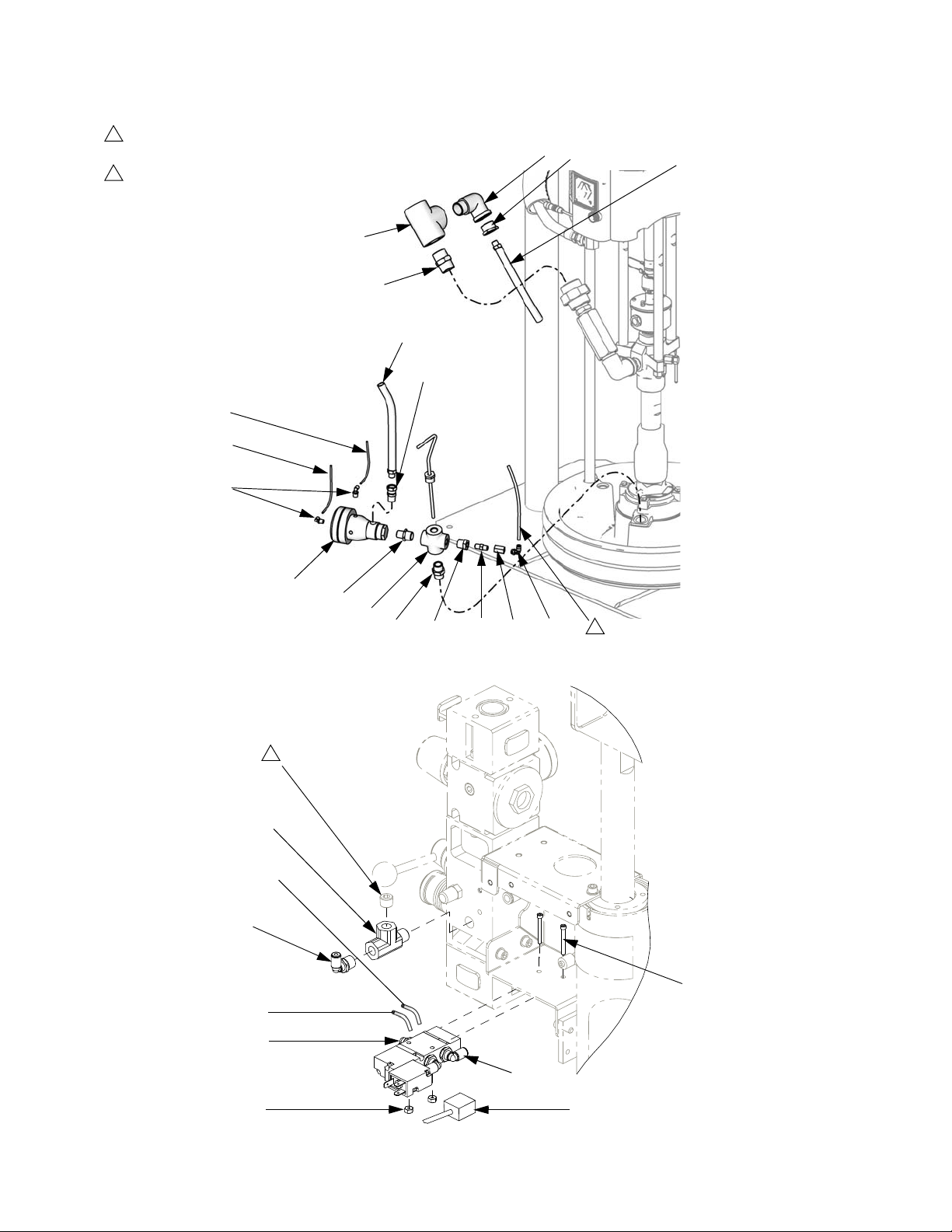
1
Remove plug from integrated air controls. Install tee fitting (523).
Assemble plug into top of tee fitting.
2
Platen blow off air line.
501
505
(Ref. 504)
508
506c
506b
524
502
503
Parts
504
523
506c (Ref)
524
506a
506b (Ref)
506a (Ref)
507
1
517
510
515 514 513
511
512
2
Solenoid Valve Detail
521
TI10886A
520
522
313529J 31
525
r_257374_313259_6a
Page 32

Accessories
Accessories
Communications Gateway Module
Communications Gateway Module CGMxx0 requires
CGK010 Mounting Kit. Use reference kit noted below
for mounting a CGM on electric tandem supply system.
See manual 313138 for installation and repair parts.
Communications
Gateway Module
Mounting Kit
CGK010
Communications Gateway
Module Part No. Fieldbus
CGMDN0 DeviceNet
CGMEP0 EtherNet/IP
CGMPB0 PROFIBUS
CGMPN0 PROFINET
See manual 312864 for CGM setup instructions.
Pressure Sensor Accessories
Sensors
Part No. Description
121175 Pressure sensor filter
Cables
Part No. Description
15Y049 M12 male/female reverse key cable
15Y037 Pressure sensor splitter cable
32 313529J
Page 33

Technical Data
Max air input pressure (supply system) psi (MPa, bar) / Air inlet size
S20 - 3 in. single post, 5 gal. (20 L) . . . . . . . . . . . . . . 125 psi (0.9 MPa, 9 bar) / 1/2 npt(f)
D60 - 3 in. dual post, 16 gal. (60 L), 8 gal. (30 L), 5 gal.
(20 L), . . . . . . . . . . . . . . . . . . . . . . . . . . . . . . . . . . . . 150 psi (1.0 MPa, 10 bar) / 3/4 npt(f)
D200 - 3 in. dual post, 55 gal. (200 L), 30 gal. (115 L),
16 gal. (60 L), 8 gal. (30 L), 5 gal. (20 L) . . . . . . . . . . 150 psi (1.0 MPa, 10 bar) / 3/4 npt(f)
D200s - 6.5 in. dual post, 55 gal. (200 L), 30 gal. (115 L) 125 psi (0.9 MPa, 9 bar) / 3/4 npt(f)
Technical Data
Max fluid, air working pressure, and weight
(displacement pump) . . . . . . . . . . . . . . . . . . . . . . . . . . . .
Pump Wetted parts . . . . . . . . . . . . . . . . . . . . . . . . . . . . . For Check-Mate displacement pumps, see manual
Platen/Ram Codes (page 5): Part number, size, platen;
Wetted parts
A, B, C, F, G, H: 255662, 55 gal. (200 L) . . . . . . . . .
J, L, M, R, S, T: 255663, 55 gal. (200 L) . . . . . . . . . . EPDM, aluminum, zinc plated carbon steel, 316 sst
4: 255661, 30 gal. (115 L) . . . . . . . . . . . . . . . . . . . . . zinc plated carbon steel, EPDM, sst, fluoroelastomer
2: 257728, 5 gal. (20 L) . . . . . . . . . . . . . . . . . . . . . . .
1, 3: 257729, 5 gal. (20 L)
0, D, E: 257734, 8 gal. (30 L)
U, V, W: 257738, 16 gal. (60 L) . . . . . . . . . . . . . . . . .
6, 7, 8, 9: 257731, 5 gal. (20 L)
K, N, P: 257736, 8 gal. (30 L)
X, Y, Z: 257741, 16 gal. (60 L) . . . . . . . . . . . . . . . . . .
For Check-Mate pump packages, see manual 312376.
For Dura-Flo pump packages, see manuals 311826,
311828, 311833.
312375.
For Dura-Flo displacement pumps, see manuals
311717, 311825, 311827.
PTFE, EPDM, PTFE coated aluminum, zinc plated
carbon steel, 316 sst
Electroless nickel, polyurethane, carbon steel, polyethylene, nitrile, zinc plated carbon steel, buna, 316 sst
17-4PH sst
Stainless steel, polyurethane, PTFE coated nitrile, polyethylene, nitrile, PTFE, 303 sst, 304 sst, 316 sst,
17-4PH sst
Electroless nickel, aramind reinforced elastomer, rubber-based PSA, polyurethane, polyethylene, nitrile, zinc
plated carbon steel, buna, 1018 carbon steel, 304 sst,
316 sst, 17-4PH sst
Ambient operating temperature range (supply system) 32-120 °F (0- 49°C)
Sound data . . . . . . . . . . . . . . . . . . . . . . . . . . . . . . . . . . . . See separate air motor manual.
External power supply requirements (DatraTrak)
AC power units. . . . . . . . . . . . . . . . . . . . . . . . . . . . . . 100-240 Vac, 50/60 Hz, single phase, 1.2 amps max
draw
DC power units . . . . . . . . . . . . . . . . . . . . . . . . . . . . . 24 Vdc, 1.2 amps max draw
313529J 33
Page 34

Graco Standard Warranty
Graco warrants all equipment referenced in this document which is manufactured by Graco and bearing its name to be free from defects in
material and workmanship on the date of sale to the original purchaser for use. With the exception of any special, extended, or limited warranty
published by Graco, Graco will, for a period of twelve months from the date of sale, repair or replace any part of the equipment determined by
Graco to be defective. This warranty applies only when the equipment is installed, operated and maintained in accordance with Graco’s written
recommendations.
This warranty does not cover, and Graco shall not be liable for general wear and tear, or any malfunction, damage or wear caused by faulty
installation, misapplication, abrasion, corrosion, inadequate or improper maintenance, negligence, accident, tampering, or substitution of
non-Graco component parts. Nor shall Graco be liable for malfunction, damage or wear caused by the incompatibility of Graco equipment with
structures, accessories, equipment or materials not supplied by Graco, or the improper design, manufacture, installation, operation or
maintenance of structures, accessories, equipment or materials not supplied by Graco.
This warranty is conditioned upon the prepaid return of the equipment claimed to be defective to an authorized Graco distributor for verification of
the claimed defect. If the claimed defect is verified, Graco will repair or replace free of charge any defective par ts. The equipment will be returned
to the original purchaser transportation prepaid. If inspection of the equipment does not disclose any defect in material or workmanship, repairs will
be made at a reasonable charge, which charges may include the costs of parts, labor, and transportation.
THIS WARRANTY IS EXCLUSIVE, AND IS IN LIEU OF ANY OTHER WARRANTIES, EXPRESS OR IMPLIED, INCLUDING BUT NOT LIMITED
TO WARRANTY OF MERCHANTABILITY OR WARRANTY OF FITNESS FOR A PARTICULAR PURPOSE.
Graco’s sole obligation and buyer’s sole remedy for any breach of warranty shall be as set forth above. The buyer agrees that no other remedy
(including, but not limited to, incidental or consequential damages for lost profits, lost sales, injury to person or property, or any other incidental or
consequential loss) shall be available. Any action for breach of warranty must be brought within two (2) years of the date of sale.
GRACO MAKES NO WARRANTY, AND DISCLAIMS ALL IMPLIED WARRANTIES OF MERCHANTABILITY AND FITNESS FOR A
PARTICULAR PURPOSE, IN CONNECTION WITH ACCESSORIES, EQUIPMENT, MATERIALS OR COMPONENTS SOLD BUT NOT
MANUFACTURED BY GRACO. These items sold, but not manufactured by Graco (such as electric motors, switches, hose, etc.), are subject to
the warranty, if any, of their manufacturer. Graco will provide purchaser with reasonable assistance in making any claim for breach of these
warranties.
In no event will Graco be liable for indirect, incidental, special or consequential damages resulting from Graco supplying equipment hereunder, or
the furnishing, performance, or use of any products or other goods sold hereto, whether due to a breach of contract, breach of warranty, the
negligence of Graco, or otherwise.
FOR GRACO CANADA CUSTOMERS
The Parties acknowledge that they have required that the present document, as well as all documents, notices and legal proceedings entered into,
given or instituted pursuant hereto or relating directly or indirectly hereto, be drawn up in English. Les parties reconnaissent avoir convenu que la
rédaction du présente document sera en Anglais, ainsi que tous documents, avis et procédures judiciaires exécutés, donnés ou intentés, à la suite
de ou en rapport, directement ou indirectement, avec les procédures concernées.
Graco Information
For the latest information about Graco products, visit www.graco.com.
TO PLACE AN ORDER, contact your Graco distributor or call to identify the nearest distributor.
Phone: 612-623-6921 or Toll Free: 1-800-328-0211 Fax: 612-378-3505
All written and visual data contained in this document reflects the latest product information available at the time of publication.
GRACO INC. AND SUBSIDIARIES • P.O. BOX 1441 • MINNEAPOLIS MN 55440-1441 • USA
Copyright 2009, Graco Inc. All Graco manufacturing locations are registered to ISO 9001.
Graco reserves the right to make changes at any time without notice.
For patent information, see www.graco.com/patents.
Original instructions. This manual contains English. MM 313529
Graco Headquarters: Minneapolis
International Offices: Belgium, China, Japan, Korea
www.graco.com
Revised July 2013
 Loading...