

Page 1
Operation
313526J
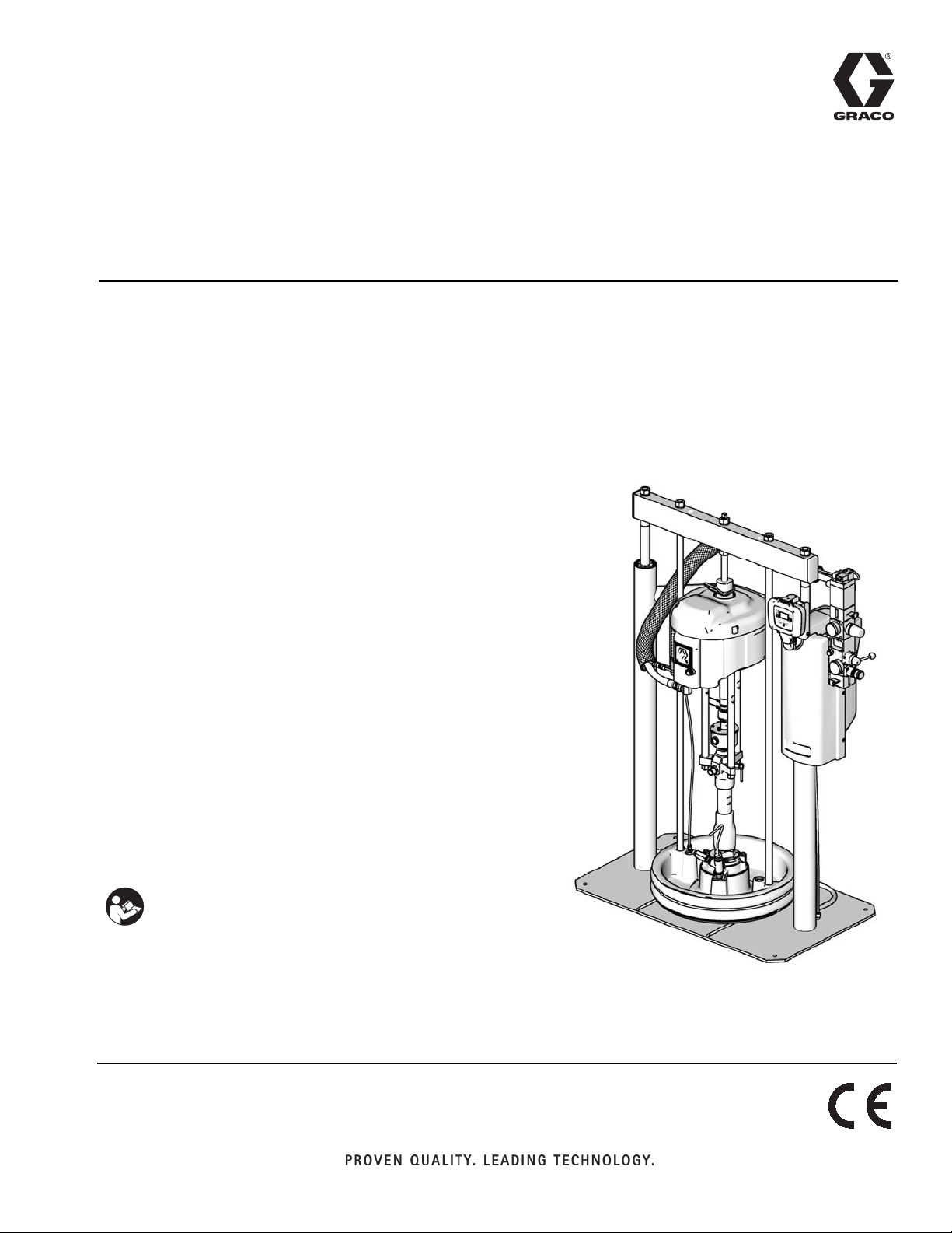
Supply Systems
For use with non-heated bulk supply of medium to high viscosity sealants and adhesive
materials. For professional use only.
Not for use in European explosive atmosphere locations.
L20c 2 inch single post elevator
20 liter (5 gallon) size
100 psi (0.7 MPa, 7 bar) Maximum Air Inlet Pressure
S20 3 inch single post
20 liter (5 gallon) size
125 psi (0.9 MPa, 9 bar) Maximum Air Inlet Pressure
EN
D60 3 inch dual post
60 liter (16 gallon) size, 30 liter (8 gallon),
20 liter (5 gallon) sizes
150 psi (1.0 MPa, 10bar) Maximum Air Inlet Pressure
D200 3 inch dual post
200 liter (55 gallon), 115 liter (30 gallon),
60 liter (16 gallon) size, 30 liter (8 gallon),
20 liter (5 gallon) sizes
150 psi (1.0 MPa, 10 bar) Maximum Air Inlet Pressure
D200S 6.5 inch dual post
55 gallon (200 liter), 30 gallon (115 liter) sizes
125 psi (0.9 MPa, 9 bar) Maximum Air Inlet Pressure
Important Safety Instructions
Read all warnings and instructions in this manual.
Save these instructions.
See page 6 for model information and approvals.
The Graco Control Architecture Electric Components are Listed in Intertek’s Directory of Listed Products.
Model CM14BA
D200
ti10429a
Page 2

Contents
Related Manuals . . . . . . . . . . . . . . . . . . . . . . . . . . . 3
Warnings . . . . . . . . . . . . . . . . . . . . . . . . . . . . . . . . . 4
Models . . . . . . . . . . . . . . . . . . . . . . . . . . . . . . . . . . . 6
Component Identification . . . . . . . . . . . . . . . . . . . 10
D200 3 in. and D200s 6.5 in. Dual Post . . . . . . 10
S20 3 in. Single Post and D60 3 in. Dual Post . 11
L20c 2in. Elevator . . . . . . . . . . . . . . . . . . . . . . . 13
L20c 2 in. Air Controls . . . . . . . . . . . . . . . . . . . . 14
Installation . . . . . . . . . . . . . . . . . . . . . . . . . . . . . . . 15
General Information . . . . . . . . . . . . . . . . . . . . . 15
Location . . . . . . . . . . . . . . . . . . . . . . . . . . . . . . 15
Grounding . . . . . . . . . . . . . . . . . . . . . . . . . . . . . 15
Mechanical Setup . . . . . . . . . . . . . . . . . . . . . . . 16
Connect Remote DataTrak to Power . . . . . . . . 16
Attach and Adjust Drum Low/Empty Sensor . . . 17
Light Tower Accessory . . . . . . . . . . . . . . . . . . . 17
Attach Drum Stops . . . . . . . . . . . . . . . . . . . . . . 18
Supply System Operation . . . . . . . . . . . . . . . . . . . 19
Pressure Relief Procedure . . . . . . . . . . . . . . . . 19
Flush Before Using Equipment . . . . . . . . . . . . . 19
Start and Adjust Ram . . . . . . . . . . . . . . . . . . . . 19
Start and Adjust Pump . . . . . . . . . . . . . . . . . . . 21
Change Drums . . . . . . . . . . . . . . . . . . . . . . . . . 21
Shutdown and Care of the Pump . . . . . . . . . . . 22
Replace Throat Seals . . . . . . . . . . . . . . . . . . . . 22
Remote DataTrak Setup . . . . . . . . . . . . . . . . . . 23
Remote DataTrak Controls and Indicators . . . . . 24
Remote DataTrak Operation . . . . . . . . . . . . . . . . . 25
Startup . . . . . . . . . . . . . . . . . . . . . . . . . . . . . . . 25
Run Mode . . . . . . . . . . . . . . . . . . . . . . . . . . . . . 25
Prime Mode . . . . . . . . . . . . . . . . . . . . . . . . . . . . 26
Setup Mode . . . . . . . . . . . . . . . . . . . . . . . . . . . . 26
Diagnostic Mode . . . . . . . . . . . . . . . . . . . . . . . . 29
Dimensions . . . . . . . . . . . . . . . . . . . . . . . . . . . . . . 34
Schematic . . . . . . . . . . . . . . . . . . . . . . . . . . . . . . . . 36
Remote DataTrak, Light Tower, Drum Low/Empty
Sensor . . . . . . . . . . . . . . . . . . . . . . . . . . . . 36
D200S, D200, S20, and D60 Supply Systems
Point of Operation Instructions . . . . . . . . . . . 37
Start and Adjust Ram . . . . . . . . . . . . . . . . . . . . 37
Start and Adjust Pump . . . . . . . . . . . . . . . . . . . 38
Change Drums . . . . . . . . . . . . . . . . . . . . . . . . . 38
Remote DataTrak Operation . . . . . . . . . . . . . . . 38
L20c Supply Systems
Point of Operation Instructions . . . . . . . . . . . 39
Start and Adjust Ram . . . . . . . . . . . . . . . . . . . . 39
Start and Adjust Pump . . . . . . . . . . . . . . . . . . . . 40
Change Drums . . . . . . . . . . . . . . . . . . . . . . . . . 40
Technical Data . . . . . . . . . . . . . . . . . . . . . . . . . . . . 41
Graco Standard Warranty . . . . . . . . . . . . . . . . . . . 42
Graco Information . . . . . . . . . . . . . . . . . . . . . . . . . 42
Note: The D200s, D200, D60, S20, and L20c Operation
Quick Guides on page 37- 40 can be removed.
2 313526J
Page 3

Related Manuals
The following manuals are available at www.graco.com.
Component Manuals in English:
Manual Description
313527 Supply Systems Repair-Parts
313528 Tandem Supply Systems Operation
313529 Tandem Supply Systems Repair-Parts
312375
312376
Check-Mate
Instructions-Parts
Check-Mate
Instruction-Parts
Dura-Flo
311827
180cc, 220cc, 290cc) Instructions-Parts
Manual
311825
311717
311828
311826
311833
312889
312467
312468
312469
312470
311238
312796
308213
Dura-Flo
580cc) Instructions-Parts Manual
Carbon Steel Displacement Pump (1000cc)
Instructions-Parts Manual
Dura-Flo
220cc, 290cc) Instructions-Parts Manual
Dura-Flo
Instructions-Parts Manual
Two-Ball NXT
Instructions-Parts Manual
60 cc Check-Mate Displacement Pump
Repair Parts Manual
100 cc Check-Mate Displacement Pump
Repair Parts Manual
200 cc Check-Mate Displacement Pump
Repair Parts Manual
250 cc Check-Mate Displacement Pump
Repair Parts Manual
500 cc Check-Mate Displacement Pump
Repair Parts Manual
™
NXT
Instructions-Parts
™
NXT
Instructions-Parts
Premier
312374 Air Controls Instructions-Parts
312491 Pump Fluid Purge Kit
®
Displacement Pumps
®
Pump Packages
™
Displacement Pumps (145cc,
™
Displacement Pumps (430cc,
™
Pump Packages (145cc, 180cc,
™
Pump Packages (430cc, 580cc)
™
Pump Packages (1000cc)
Air Motor (Nxxxxx models)
Air Motor (Mxxxxx models)
®
Air Motor Instructions-Parts
Related Manuals
312492 Drum Roller Kit Instruction
312493 Light Tower Kit Instruction
406681 Platen Cover Kit
313526J 3
Page 4
Warnings
Warnings
The following warnings are for the setup, use, grounding, maintenance, and repair of this equipment. The exclamation point symbol alerts you to a general warning and the hazard symbol refers to procedure-specific risk. Refer back
to these warnings. Additional, product-specific warnings may be found throughout the body of this manual where
applicable.
WARNING
SKIN INJECTION HAZARD
High-pressure fluid from gun, hose leaks, or ruptured components will pierce skin. This may look like just
a cut, but it is a serious injury that can result in amputation. Get immediate surgical treatment.
• Do not point gun at anyone or at any part of the body.
• Do not put your hand over the dispense outlet.
• Do not stop or deflect leaks with your hand, body, glove, or rag.
•Follow Pressure Relief Procedure in this manual, when you stop dispensing and before cleaning,
checking, or servicing equipment.
MOVING PARTS HAZARD
Moving parts can pinch or amputate fingers and other body parts.
• Keep clear of moving parts.
• Do not operate equipment with protective guards or covers removed.
• Pressurized equipment can start without warning. Before checking, moving, or servicing equipment,
follow the Pressure Relief Procedure in this manual. Disconnect power or air supply.
FIRE AND EXPLOSION HAZARD
Flammable fumes, such as solvent and paint fumes, in work area can ignite or explode. To help prevent
fire and explosion:
• Use equipment only in well ventilated area.
• Eliminate all ignition sources; such as pilot lights, cigarettes, portable electric lamps, and plastic drop
cloths (potential static arc).
• Keep work area free of debris, including solvent, rags and gasoline.
• Do not plug or unplug power cords, or turn power or light switches on or off when flammable fumes
are present.
• Ground all equipment in the work area. See Grounding instructions.
• Use only grounded hoses.
• Hold gun firmly to side of grounded pail when triggering into pail.
• If there is static sparking or you feel a shock, stop operation immediately. Do not use equipment
until you identify and correct the problem.
• Keep a working fire extinguisher in the work area.
4 313526J
Page 5
Warnings
WARNING
EQUIPMENT MISUSE HAZARD
Misuse can cause death or serious injury.
• Do not operate the unit when fatigued or under the influence of drugs or alcohol.
• Do not exceed the maximum working pressure or temperature rating of the lowest rated system
component. See Technical Data in all equipment manuals.
• Do not leave the work area while equipment is energized or under pressure. Turn off all equipment
and follow the Pressure Relief Procedure in this manual when equipment is not in use.
• Check equipment daily. Repair or replace worn or damaged parts immediately with genuine manufacturer’s replacement parts only.
• Do not alter or modify equipment.
• Use equipment only for its intended purpose. Call your distributor for information.
• Route hoses and cables away from traffic areas, sharp edges, moving parts, and hot surfaces.
• Do not kink or over bend hoses or use hoses to pull equipment.
• Keep children and animals away from work area.
• Comply with all applicable safety regulations.
ELECTRIC SHOCK HAZARD
This equipment must be grounded. Improper grounding, setup, or usage of the system can cause electric shock.
• Turn off and disconnect power cord before servicing equipment.
• Use only grounded electrical outlets.
• Use only 3-wire extension cords.
• Ensure ground prongs are intact on power and extension cords.
• Do not expose to rain. Store indoors.
SPLATTER HAZARD
Hot or toxic fluid can cause serious injury if splashed in the eyes or on skin. During blow off of platen,
splatter may occur.
• Use minimum air pressure when removing platen from drum.
TOXIC FLUID OR FUMES HAZARD
Toxic fluids or fumes can cause serious injury or death if splashed in the eyes or on skin, inhaled, or
swallowed.
• Read MSDS’s to know the specific hazards of the fluids you are using.
• Store hazardous fluid in approved containers, and dispose of it according to applicable guidelines.
• Always wear impervious gloves when spraying or cleaning equipment.
• If this equipment is used with isocyanate material, see additional information on isocyanites in Isocyanate Conditions Section of this manual.
PERSONAL PROTECTIVE EQUIPMENT
You must wear appropriate protective equipment when operating, servicing, or when in the operating
area of the equipment to help protect you from serious injury, including eye injury, inhalation of toxic
fumes, burns, and hearing loss. This equipment includes but is not limited to:
• Protective eyewear
• Clothing and respirator as recommended by the fluid and solvent manufacturer
•Gloves
• Hearing protection
313526J 5
Page 6
Models
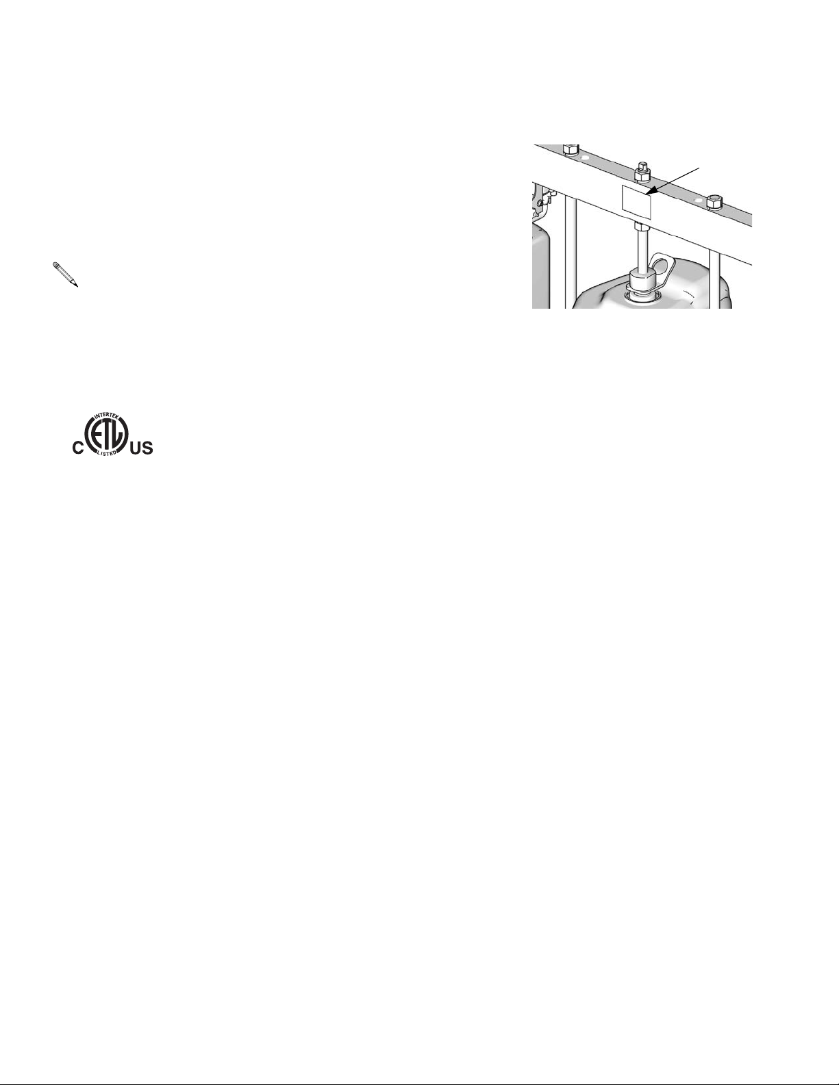
Models
Check the identification plate (ID) for the 6-digit part number of the supply system. Use the following matrix to define the construction of the supply system,
based on the six digits. For example, Part No. CM14BA represents a
®
Check-Mate supply system (CM), a carbon steel Check-Mate 100 MaxLife
displacement pump with an NXT 2200 air motor with remote DataTrak (pump
code 14), a 3 in. dual post ram with integrated air controls (B) and a 55-gallon,
uncoated platen with a neoprene seal (A).
Systems with the GD as the first and second digits are Dura-Flo supply
systems.
Some configurations in the following matrix cannot be built. See the
Product Selection guide for available systems.
To order replacement parts, see Parts section in manual 313527. The digits in the matrix on the next page do not
correspond to the Ref. Nos. in the Parts drawings and lists.
All supply systems with DataTrak and 24 Vdc or 100-240 Vac power supplies are ETL approved.
2ECOGNIZED#OMPONENT
#-
ID
ti11157a
#ERTIFIEDTO#!.#3!#3!#.O
#ONFORMSTO5,
6 313526J
Page 7

Models
CM 14 B
First and
Second Digit
CM
(Supply
System with
Check-Mate
displacement
pump)
GD
(Supply
System with
Dura-Flo
displacement
pump)
Third and
Fourth Digit Fifth Digit
Pump Code
(See Table 1
for 2-digit
Check-Mate
Pump Code)
(See Table 2
for 2-digit
Dura-Flo
Pump Code)
Size Style
1 2 in. L20c no volt
2 3 in. S20c no volt INT C
3 3 in. S20 no volt INT F
4 3 in. D60 no volt INT G
5 3 in. D200 no volt INT H
6 3 in D200i no volt
7 6.5 in. D200s no volt INT K
8 6.5 in. D200si no volt
9 3 in. D200 24 Vdc INT M
A 3 in. D200i 24 Vdc
B 3 in. D200
C 3 in. D200i
F 6.5 in. D200s 24 Vdc INT U
G 6.5 in. D200si 24 Vdc
H 6.5 in. D200s
J 6.5 in. D200si
L 3 in. S20
M 3 in. S20 24 Vdc INT 9
R 3 in. D60
T 3 in. D60i
U 3 in. D60 24 Vdc INT
W 3 in. D60i 24 Vdc
Y 3 in. D60i no volt
Ram Options
DataTra
k
Voltage Air Controls
2-Button Inter-
2-Button Inter-
2-Button Inter-
100-240
Vac INT S
100-240
Vac
100-240
Vac INT Y
100-240
Vac
100-240
Vac INT 8
100-240
Vac INT A
100-240
Vac
2-Button Inter-
2-Button Inter-
2-Button Inter-
2-Button Inter-
2-Button Inter-
2-Button Inter-
Air Control
Panel B
lock J
lock L
lock R
lock T
lock W
lock 7
lock
lock
lock
A
Sixth Digit
Platen and Seal Options
Platen
Size
20 L
(5 Gal) F, SW CS Nitrile
20 L
(5 Gal) F, SW CS
20 L
(5 Gal) F, SW SST
20 L
(5 Gal) F, DW CS Nitrile
20 L
(5 Gal) F, DW CS
30 L
(8 Gal) F, SW CS Nitrile
30 L
(8 Gal) F, SW CS
30 L
(8 Gal) F, SW SST
30 L
(8 Gal) F, DW CS Nitrile
30 L
(8 Gal) F, DW CS
60 L
(16 Gal) F, SW CS Nitrile
60 L
(16 Gal) F, SW CS
60 L
(16 Gal) F, SW SST
60 L
(16 Gal) F, DW CS Nitrile
60 L
(16 Gal) F, DW CS
115 L
30 Gal D CS EPDM
200 L
(55 Gal) DR
200 L
(55 Gal) DR AL EPDM
200 L
(55 Gal) DR AL Neoprene
Platen
Style
Platen
MaterialSeal
Material
Polyure-
thane
PTFE
coated
Polyure-
thane
Polyure-
thane
PTFE
coated
Polyure-
thane
Polyure-
thane
PTFE
coated
Polyure-
thane
PTFE
coated
AL EPDM
KEY:
S = Single post ram i = 2-Button Interlock F = Flat SW = Single wiper
c = Cart mounted s = 6.5 inch D = D Style DW = Double wiper
D = Dual post ram INT = Integrated air controls DR = Dual o-ring
* Other Available Models: 262868. This model is the same as CM-_ _-3-B models, such as CM-11-3-B, but uses Check-Mate
Pump P40DCS (NXT2200/CM 100) instead of the other pumps listed on page 8.
313526J 7
Page 8

Models
Table 1: Check-Mate Pump Identification Code/Part No. Index
Pump Part No.
Pump
Code
(see manual
312376)
NXT 200/CM 60
4A P05LCS
4B P05LCM
4C P05LSS
4F P05LSM
NXT 400/CM 60
6A P11LCS
6B P11LCM
6C P11LSS
6F P11LSM
6G P11RCS
6H P11RCM
6J P11RSS
6K P11RSM
61 P11SCS
62 P11SCM
63 P11SSS
64 P11SSM
NXT 700/CM 60
7A P20LCS
7B P20LCM
7C P20LSS
7F P20LSM
7G P20RCS
7H P20RCM
7J P20RSS
7K P20RSM
71 P20SCS
72 P20SCM
73 P20SSS
74 P20SSM
NXT 1200/CM 60
8A P38LCS
8B P38LCM
8C P38LSS
8F P38LSM
8G P38RCS
8H P38RCM
8J P38RSS
8K P38RSM
Pump Part No.
Pump
Code
(see manual
312376)
81 P38SCS
82 P38SCM
83 P38SSS
84 P38SSM
NXT 1800/CM 60
9A P61LCS
9B P61LCM
9C P61LSS
9F P61LSM
9G P61RCS
9H P61RCM
9J P61RSS
9K P61RSM
91 P61SCS
92 P61SCM
93 P61SSS
94 P61SSM
NXT 2200/CM 100
11 P40LCS
12 P40LCM
1F P40LSS
1G P40LSM
13 P40RCS
14 P40RCM
1H P40RSS
1J P40RSM
10 P40SSS
1A P40SSM
19 P40SCS
NXT 3400/CM 100
15 P63LCS
16 P63LCM
1T P63LSS
1U P63LSM
17 P63RCS
18 P63RCM
1W P63RSS
1Y P63RSM
1B P63SSS
1C P63SSM
Pump Part No.
Pump
Code
(see manual
312376)
NXT 2200/CM 200
21 P23LCS
22 P23LCM
23 P23RCS
24 P23RCM
25 P23LSS
26 P23LSM
27 P23RSS
28 P23RSM
NXT 3400/CM 200
29 P36LCS
2A P36LCM
2B P36RCS
2C P36RCM
2F P36LSS
2G P36LSM
2H P36RSS
2J P36RSM
NXT 6500/CM 200
2L P68LCS
2M P68LCM
2R P68RCS
2S P68RCM
2T P68LSS
2U P68LSM
2W P68RSS
2Y P68RSM
20 P68SCS
NXT 3400/CM 250
31 P29LCS
32 P29LCM
33 P29RCS
34 P29RCM
35 P29LSS
36 P29LSM
37 P29RSS
38 P29RSM
Pump Part No.
Pump
Code
(see manual
312376)
NXT 6500/CM 250
39 P55LCS
3A P55LCM
3B P55RCS
3C P55RCM
3F P55LSS
3G P55LSM
3H P55RSS
3J P55RSM
Premier/CM 250
3L P82LCS
3M P82LCM
3R P82LSS
3S P82LSM
NXT 3400/CM 500
51 P14LCS
52 P14LCM
53 P14RCS
54 P14RCM
55 P14LSS
56 P14LSM
57 P14RSS
58 P14RSM
NXT 6500/CM 500
59 P26LCS
5A P26LCM
5B P26RCS
5C P26RCM
5F P26LSS
5G P26LSM
5H P26RSS
5J P26RSM
Premier/CM 500
5L P39LCS
5M P39LCM
5R P39LSS
5S P39LSM
No Pump
NN
See manual 312376 or the ID plate on the pump to determine pump part number.
8 313526J
Page 9

Table 2: Dura-Flo Pump Identification Code/Part No. Index
Models
Pump Part No.
Pump
Code
(see manual
311828)
NXT 2200/DF 145SS
A1 P31LSS
A3 P31HSS
NXT 3400/DF 145SS
B1 P46LSS
B3 NR
NXT 3400/DF 180SS
B5 P41LSS
B7 P41HSS
NXT 3400/DF 220SS
C1 P30LSS
C3 P30HSS
NXT 6500/DF 220SS
CA P57LSS
CC NR
NXT 6500/DF 290SS
D1 P45LSS
D3 NR
Premier/DF 290SS
DL P67LSS
DR NR
Pump Part No.
Pump
Code
(see manual
311826)
NXT 3400/DF 430CS
E1 NR
E2 NR
E3 NR
E4 NR
NXT 3400/DF 430SS
E5 P15LSS
E6 P15LSM
E7 P15HSS
E8 P15HSM
NXT 6500/DF 430CS
E9 NR
EA NR
EB NR
EC NR
NXT 6500/DF 430SS
EF P32LSS
EG P32LSM
EH P32HSS
EJ P32HSM
Premier/DF 430
EL P44LSS
EM NR
ER NR
ES NR
ET P44LCS
NXT 3400/DF 580CS
F1 NR
F2 NR
F3 NR
F4 NR
NXT 3400/DF 580SS
F5 P12LSS
F6 P12LSM
F7 P12HSS
F8 P12HSM
Pump Part No.
Pump
Code
(see manual
311826)
NXT 6500/DF 580CS
F9 P22LCS
FA NR
FB NR
FC NR
NXT 6500/DF 580SS
FF P22LSS
FG P22LSM
FH P22HSS
FJ P22HSM
Premier/DF 580CS
FL P34LSS
FM NR
FR NR
FS NR
FT P34LCS
Pump Part No.
Pump
Code
(see manual
311833)
NXT 3400/DF 1000CS
G1 P06LCS
G3 NR
NXT 3400/DF 1000SS
G5 NR
G7 NR
NXT 6500/DF 1000CS
G9 P10LCS
GB NR
NXT 6500/DF 1000SS
GF NR
GH NR
Premier/DF 1000
GL NR
GM NR
GR NR
GS NR
NR = Not released
313526J 9
Page 10
Component Identification
Component Identification
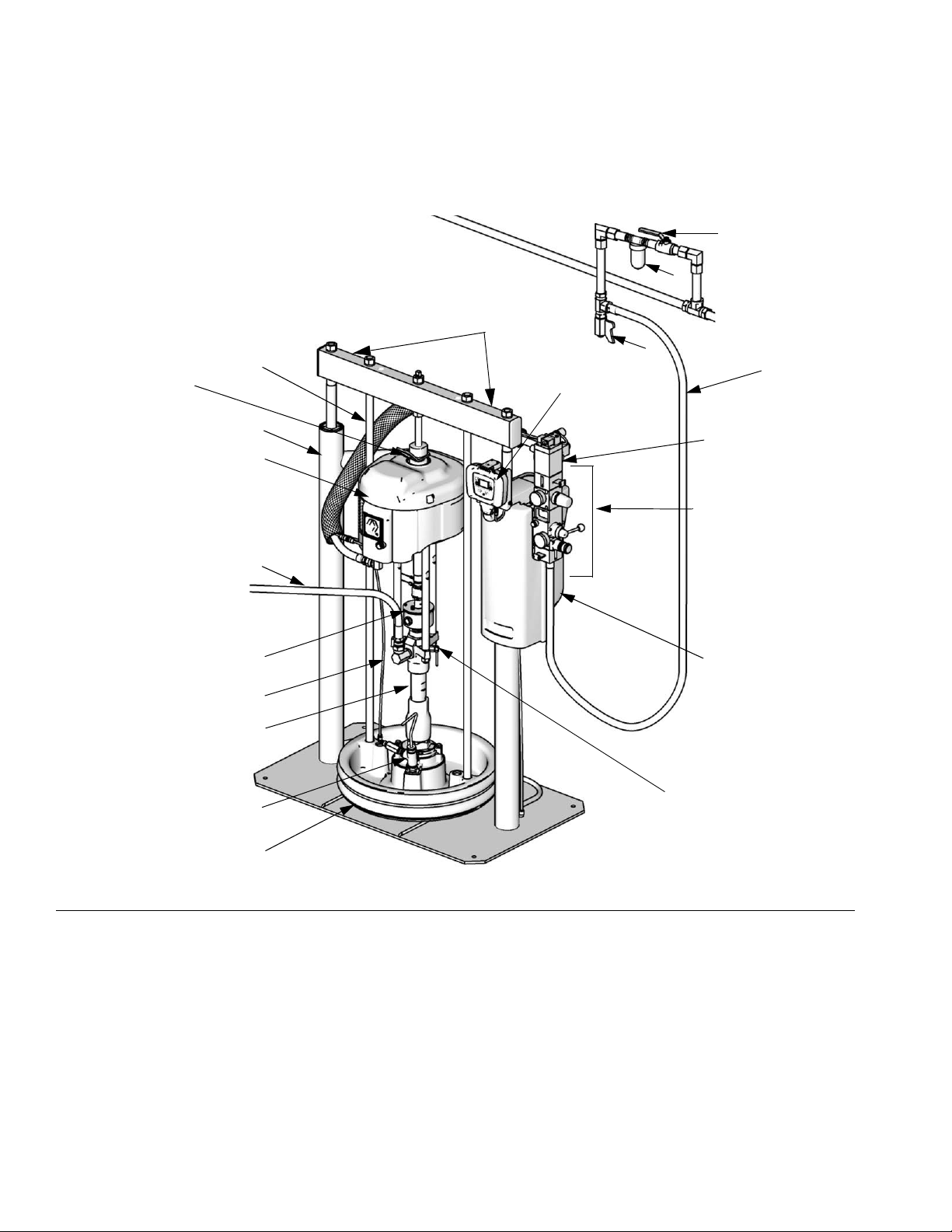
D200 3 in. and D200s 6.5 in. Dual Post
W
H
(Note: Do not use motor
lift ring to lift entire
system.)
CM14BA Model
Shown
N
A
B
S
R
M
V
Lift Locations
U
T
E
X
G
K
C
J
D
FIG. 1
Key:
ARam Assembly
B Air Motor
C Displacement Pump
DPlaten
E Remote DataTrak (single ram systems) or
Display Module (tandem systems)
IG
G Integrated Air Controls (see F
H Air Motor Lift Ring
J Platen Bleed Port
K Power Supply Box
M Blowoff Air Supply Line
. 3)
P
TI10430a
N Platen Lift Rod
P Pump Bleeder Valve
R Enclosed Wet Cup
S Fluid Line (not supplied)
T Main Air Line (not supplied)
U Air Line Drain Valve (not supplied)
V Air Filter (not supplied)
W Bleed Type Air Shutoff Valve (not supplied)
X Air Motor Solenoid
10 313526J
Page 11
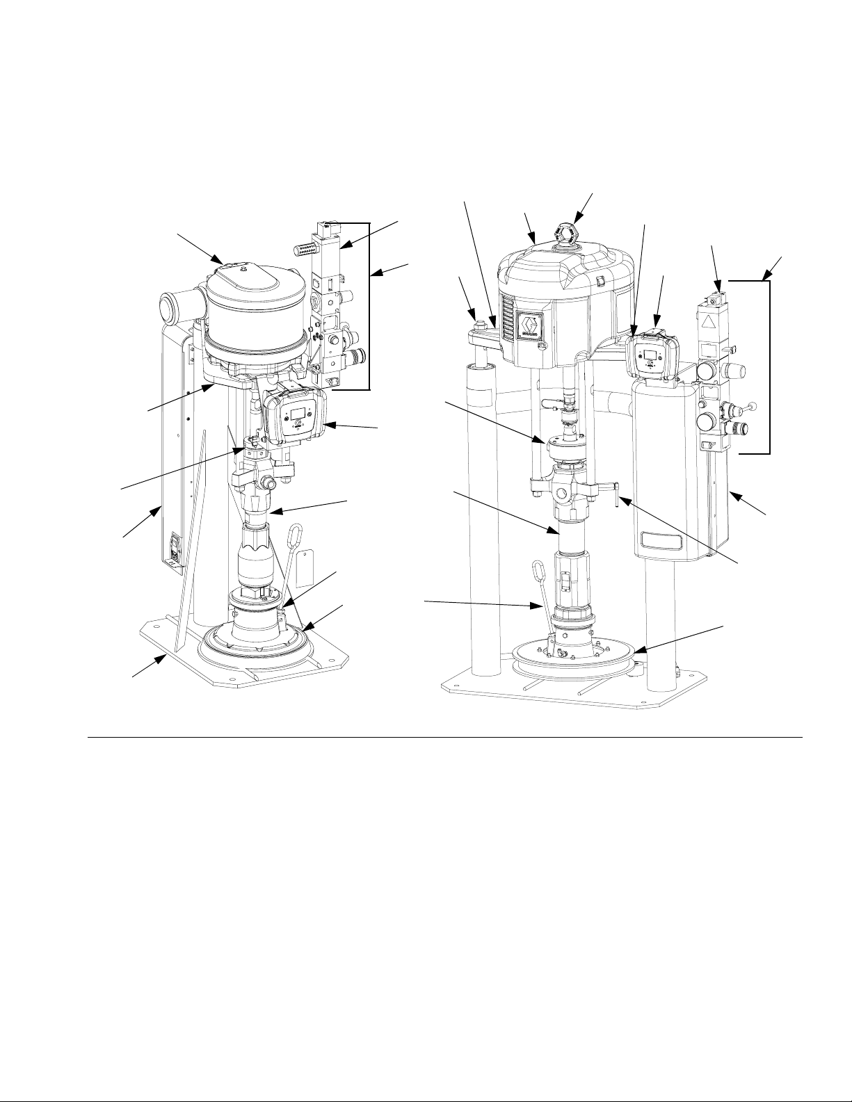
S20 3 in. Single Post and D60 3 in. Dual Post
Model CM9HLB Shown Model CM2MRY Shown
Lift Location
B
X
G
A
B
H
Component Identification
(Note: Do not use motor
lift ring to lift entire
system.)
Lift Location
X
G
F
Lift
Location
R
K
A
r_255648_313527_5a
FIG. 2
Key:
ARam Assembly
B Air Motor
C Displacement Pump
DPlaten
F Remote DataTrak (single ram systems) or
Display Module (tandem systems)
IG
G Integrated Air Controls (see F
H Lift Ring
J Platen Bleed Port
K Power Supply Box (under shrouding)
P Pump Bleed Valve
R Enclosed Wet Cup
S Fluid Line (not supplied, see F
T Air Line (not supplied, see F
U Air Line Drain Valve (not supplied, see F
V Air Filter (not supplied, see F
. 3)
IG
. 1)
IG
. 1)
IG
. 1)
R
F
C
C
K
J
D
J
P
D
r_255648_313527_6a
IG
W Bleed Type Air Shutoff Valve (not supplied, see F
X Air Motor Solenoid
IG
. 1)
. 1)
313526J 11
Page 12
Component Identification
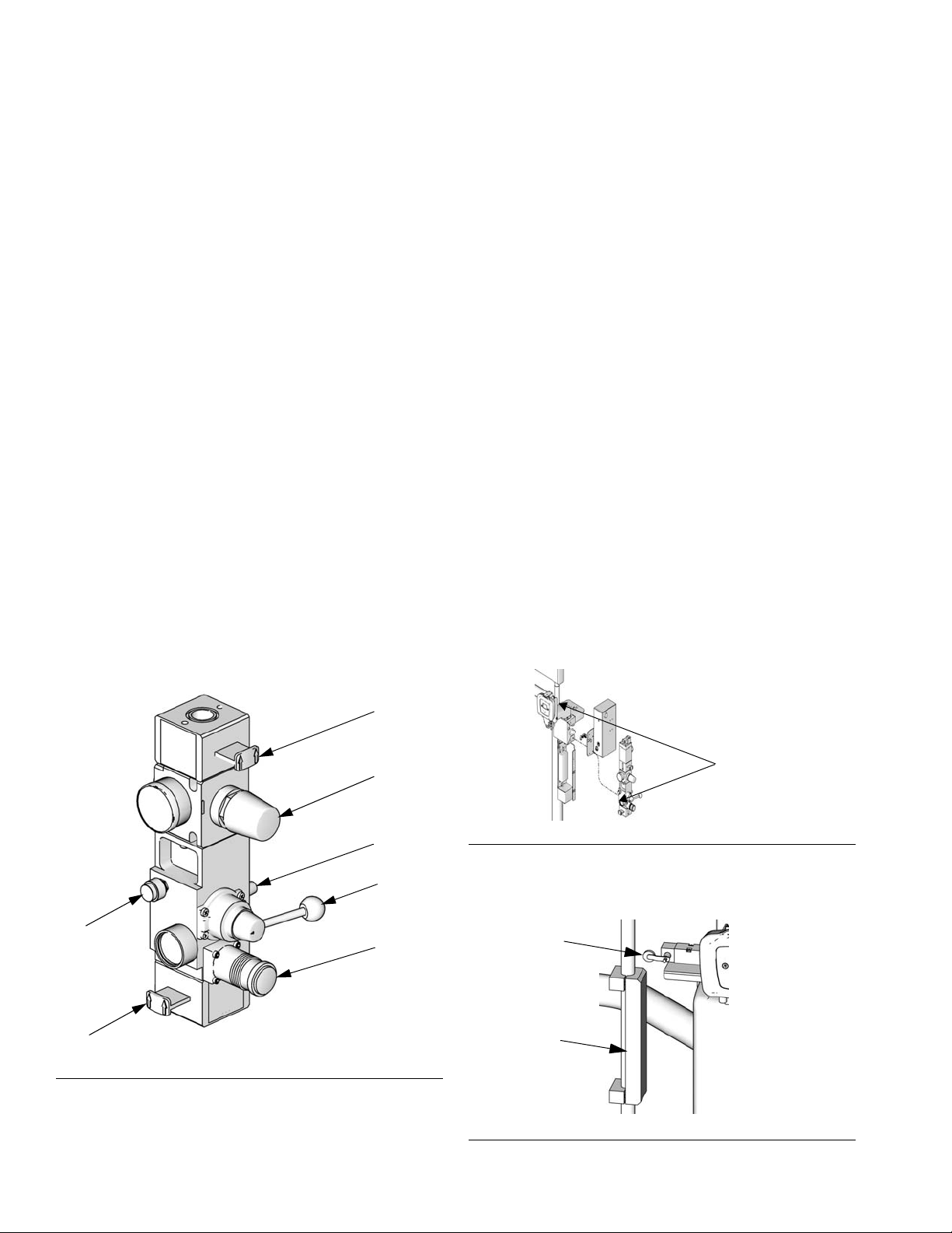
Integrated Air Controls
D200, D200s, D60, and S20 Models
The integrated air controls include:
• Main air slider valve (BA): turns air on and off to
the system. When closed, the valve relieves pressure downstream.
• Ram air regulator (BB): controls ram up and down
pressure and blowoff pressure.
• Ram director valve (BC): controls ram direction.
• Exhaust port with muffler (BD)
• Air motor regulator (BE): Controls air pressure to
motor.
• Air motor slider valve (BF): turns air on and off to
the air motor. When closed, the valve relieves air
trapped between it and the air motor. Push the valve
in to shutoff. Remote DataTrak: The air solenoid
(X, F
IG
. 1), the air motor slider valve (BF), and the
main air slider valve (BA) must be open for air to
flow. (See Remote DataTrak Setup, page 23.)
• Blowoff button (BG): turns air on and off to push
the platen out of an empty drum.
Air Line Accessories
See FIG. 1.
• Air line drain valve (U)
• Air line filter (V): removes harmful dirt and mois-
ture from compressed air supply.
• Second bleed-type air valve (W): isolates air line
accessories and supply system for servicing. Locate
upstream from all other air line accessories.
• Air relief valve (attached to ram air regulator, not
visible): automatically relieves excessive pressure.
2-Button Interlock Air Controls
D60i, D200i, and D200si Models
Units that have 2-Button Interlock controls have the following additional components:
• 2-Button Module: See manual 312374 for
information.
• Roller switch (CA): shuts off air supply when it
contacts the bracket actuator. Operator must push
and hold the activation buttons simultaneously to
resume ram movement.
BG
BA
F
IG
. 3. Integrated Air Controls
ti10438a
BF
BE
BD
BC
BB
Activation
Buttons
ti10843a1
FIG. 4
• Bracket actuator (CB): attaches to the platen lift
rod. When platen is outside of drum, actuator makes
contact with the roller switch.
CA
CB
ti10846a
F
IG
. 5
12 313526J
Page 13
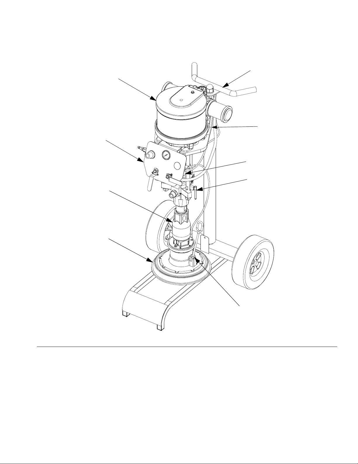
L20c 2in. Elevator
Component Identification
CM7B1G Model Shown
CF
CC
CD
CA
CB
Lift Location
CE
P
J
r_257032_312376_1e
FIG. 6
Key:
CA Elevator Cart
CB Air Motor
CC Displacement Pump
CD Platen
CE Enclosed Wet Cup (behind air controls)
CF Elevator and Pump Air Controls
J Platen Bleed Port
P Pump Bleed Valve
313526J 13
Page 14

Component Identification
L20c 2 in. Air Controls
• Air motor regulator (DA): Controls air pressure to
motor.
• Blowoff button (DB): turns air on and off to push
the platen out of an empty drum.
• Air motor shutoff valve (DC): turns air on and off
to the air motor.
• Elevator director valve (DD): controls elevator
direction.
DB
DA
DC
F
IG
. 7: Elevator Air Controls
DD
r_257302_312376_2e
Air and Fluid Hoses
Be sure all air hoses (T) and fluid hoses (S) are properly
sized and pressure-rated for your system. Use only
electrically conductive hoses. Fluid hoses must have
spring guards on both ends. Use of a short whip hose
and a swivel between the main fluid hose and the
gun/valve allows freer gun/valve movement.
14 313526J
Page 15

Installation
Installation
General Information
Reference numbers and letters in parentheses in
the text refer to the callouts in the figures.
Accessories are available from Graco. Make certain all
accessories are adequately sized and pressure-rated to
meet the system’s requirements.
F
IG
. 1, FIG. 2, and FIG. 6 are only guides for selecting
and installing system components and accessories.
Contact your Graco distributor for assistance in designing a system to suit your particular needs.
Location
NOTICE
Always lift supply system at proper lift locations (see
F
IG
. 1, FIG. 2, and FIG. 6). Do not lift in any other way.
Attach a lifting sling at the proper lift spots. Lift off the
pallet using a crane or a forklift.
Position the ram so the air controls are easily accessible. Ensure that there is enough space overhead for the
ram to raise fully. (See Dimensions, page 34.)
Pump: use a ground wire and clamp. Loosen grounding
lug locknut and washer. Insert one end of supplied
ground wire into slot in lug and tighten locknut securely.
Connect other end of wire to a true earth ground. See
F
IG
. 8.
ti8250a
FIG. 8
Air and fluid hoses: use only electrically conductive
hoses with a maximum of 500 ft. (150 m) combined
hose length to ensure grounding continuity. Check electrical resistance of hoses. If total resistance to ground
exceeds 29 megohms, replace hose immediately.
Air compressor: follow manufacturer’s recommendations.
Spray gun/dispense valve: ground through connection
to a properly grounded fluid hose and pump.
Fluid supply container: follow local code.
Using the holes in the ram base as a guide, drill holes
for 1/2 in. (13 mm) anchors.
Ensure that the ram base is level in all directions. If necessary, level the base using metal shims. Secure the
base to the floor using 1/2 in. (13 mm) anchors that are
long enough to prevent the ram from tipping.
Grounding
NOTICE
The equipment must be grounded. Grounding
reduces the risk of static and electric shock by providing an escape wire for the electrical current due to
static build up or in the event of a short circuit.
313526J 15
Object being sprayed: follow local code.
Solvent pails used when flushing: follow local code.
Use only conductive metal pails, placed on a grounded
surface. Do not place the pail on a nonconductive surface, such as paper or cardboard, which interrupts
grounding continuity.
To maintain grounding continuity when flushing or
relieving pressure: hold metal part of the dispense
valve firmly to the side of a grounded metal pail, then
trigger the valve.
Page 16

Installation
Mechanical Setup
1. Fill displacement pump wet cup 2/3 full with Graco
Throat Seal Liquid (TSL).
2. Back-off air regulators to their full counterclockwise
position and close all shutoff valves.
3. Connect air line from an air source to the system air
inlet. See F
mance curves in manual 312376 to determine your
air supply flow requirements. Use a supply hose
capable of meeting the required flow.
Quick disconnects restrict flow for large air motors.
Connect Remote DataTrak to Power
100-240 Vac
The system has an IEC-C14 power input connection
located on the back of the power supply box. The user
must supply an appropriate adapter. The 100-240 Vac
supply must be capable of sourcing at least 1.2 Amps
and have supply current protection rated in accordance
with the supply wire gauge provided.
Frequency Voltage Max. Current Phase
50-60 Hz 100-240 Vac 1.2 Amps 1
IG
. 1 or FIG. 2. Refer to the pump perfor-
24 Vdc
Attach 24V Class 2 power supply to terminals on the
24V assembly: +24 Vdc to terminal 2 (+) and -24 Vdc to
terminal 5 (-). Attach protective earthing (PE) conductor
to terminal marked .
5 (-)
PE
ti10853a
The 24 Vdc supply must be capable of supplying at least
1.2 Amps and have supply current protection rated at no
more than 2.5 Amps.
Voltage Max. Current
24 Vdc 1.2 Amps
2 (+)
ti10985a
Have a trained electrician install and inspect power connection per local code. Plug power supply cord into the
outlet on the back of the power supply box and into a
properly grounded electrical outlet. Use a zip tie, if
needed, to secure power cord in place.
ti10433a
Have a trained electrician install and inspect power connection per local code.
16 313526J
Page 17

Installation
Attach and Adjust Drum Low/Empty Sensor
For supply systems with remote DataTrak, an optional
kit can be purchased to indicate either when the drum is
low or when it is empty. Order kit 255469 for a D60 or
D200 3 in. ram, 255689 for a D200s 6.5 in. ram, or
257634 for a S20 3 in. ram.
1. Position ram at desired level (low or empty).
2. Attach low/empty sensor bracket (EA) to mounting
bracket (EB).
EA
EE
ED
4. For D60, D200, and D200s supply systems: Attach
the actuator (ED) to the ram piston rod, near the top,
so it passes in front of the sensor (EE) at the correct
level for drum low or drum empty. See F
For D60 supply systems: Flip actuator bracket (ED)
so that it points upwards instead of downwards to
allow it to pass the sensor (EE).
5. For S20 supply systems: Attach the actuator (ED) to
the ram cylinder endcap, so the sensor (EE) passes
in front of the bracket (ED) at the correct level for
drum low or drum empty. See F
6. Make precise adjustments by moving the sensor
within the slot on the sensor bracket.
7. Attach the sensor to the corresponding connector
on the D-Sub harness of the remote DataTrak.
IG
. 10.
IG
. 9.
Light Tower Accessory
Order the 255467 Light Tower Accessory as a diagnostic indicator for D200s, D200, D60, and S20 supply systems. See T
signals.
ABLE
3 for a description of light tower
EB
F
IG
. 9: D200 and D200s supply systems
EB
EA
ED
EE
r_cm9hlb_313526_3a
F
IG
. 10: S20 supply systems
3. To measure either drum low or drum empty, attach
one sensor (EE) to the sensor bracket (EA).
Table 3: Light Tower Signals
Signal Description
Yellow flashing A low priority error exists.
Yellow on A medium priority error exists.
Red flashing A high priority error exists.
Red on The system is shut down due to
error conditions.
313526J 17
Page 18

Installation
Attach Drum Stops
Only D200s, D200, and D60 Supply systems are
shipped with drum stops in place to help position the
drum on the ram. For replacement parts, order Kit
255477. The kit includes 2 each of capscrews (FA), lock
washers (not shown), and drum stops (FB).
FB
F
IG
. 11
FA
ti10917a
1. Locate the correct set of mounting holes on the ram
base.
2. Using the capscrews (FA) and lock washers (not
shown), attach the drum stops (FB) to the ram base.
55 gal (200 L)
8 gal (30 L)
FIG. 12: Ram Base
D200 and D200s Base D60 Base
30 gal (115 L)
8 gal (30 L)
16 gal (60 L)
5 gal (20 L)
5 gal (20 L)
60 gal (16 L)
18 313526J
Page 19

Supply System Operation
Pressure Relief Procedure
1. Lock the gun/valve trigger.
Supply System Operation
Flush Before Using Equipment
The pump was tested with lightweight oil, which is left in
the fluid passages to protect parts. To avoid contaminating fluid with oil, flush the pump with a compatible solvent before use. See pump manual for flushing
directions.
2. For D200s, D200, S20, and D60 Air Controls: See
F
IG
. 3, page 12.
a. Close the air motor slider valve (BF) and the
main air slider valve (BA).
b. Set the ram director valve (BC) to DOWN. The
ram will slowly drop.
c. Jog the director valve up and down to bleed air
from ram cylinders.
IG
3. For L20c Air Controls: See F
a. Close the air motor valve (DC) and the elevator
director valve (DD). The ram will slowly drop.
4. Unlock the gun/valve trigger.
5. Hold a metal part of the gun/valve firmly to the side
of a grounded metal pail, and trigger the gun/valve
to relieve pressure.
6. Lock the gun/valve trigger.
7. Open the fluid line drain valve and the pump bleeder
valve (P). Have a container ready to catch the drainage.
8. Leave the pump bleeder valve (P) open until ready
to spray again.
If you suspect that the spray tip/nozzle or hose is completely clogged, or that pressure has not been fully
relieved after following the steps above, very slowly
loosen the tip guard retaining nut or hose end coupling
and relieve pressure gradually, then loosen completely.
Now clear the tip/nozzle or hose.
. 7, page 14.
Start and Adjust Ram
D200 3 in. and D200s 6.5 in. Dual Post
Moving parts can pinch or amputate fingers. When the
pump is operating and when raising or lowering the
ram, keep fingers and hands away from the pump
intake, platen, and lip of the drum.
1. Refer to FIG. 1 and FIG. 3. Close all air regulators
and air valves.
2. Open main air slider valve (BA) and set ram air regulator (BB) to 40 psi (0.28 MPa, 2.8 bar). Set director valve handle (BC) to UP and let the ram rise to
its full height. 2-Button Interlock: If the system has
this feature, ram will stop as it nears the top. Press
and hold both buttons to raise ram completely. See
F
IG
. 3 on page 12.
3. Lubricate the platen seals (D) with grease or other
lubricant compatible with the fluid you will pump.
4. Remove the drum cover and smooth the surface of
the fluid with a straightedge.
5. Put a full drum of fluid on the ram base, slide it back
against the drum stops, and center it under the
platen (D). An optional drum roller kit is available for
D200 and D200s supply systems to make it easier
to load the drum on the base. Order Kit 255627.
To avoid damage to the platen seals, do not use a
drum that is dented or damaged.
313526J 19
Page 20

Supply System Operation
6. Remove bleed stick from platen bleed port (J).
7. If drum has a plastic liner, pull it over edge of drum.
Secure liner with tape wrapped around circumference of drum.
J
D
F
IG
. 13
ti10543a
8. Set the director valve (BC) to DOWN and lower the
ram until fluid appears at the top of the platen bleed
port (J). Adjust ram air regulator (BB) as needed.
Set the director valve (BC) to neutral and close the
platen bleed port (J). 2-Button Interlock: If system
has this feature, press and hold both buttons to start
lowering the ram. See F
IG
. 3, page 12.
L20c 2 in. Elevator, S20 3 in. Single Post,
and D60 3 in. Single Post
1. Raise ram:
a. For S20 and D60: Open the main air slider
valve (BA) and set the ram air regulator (BB) to
40 psi (0.28 MPa, 2.8 bar). Set director valve
handle (BC) to UP and let the ram rise to its full
height. 2-Button Interlock: If the system has
this feature, ram will stop as it nears the top.
Press and hold both buttons to raise ram completely. See F
IG
. 3 on page 12.
being trapped under the platen, scoop fluid from the
center of the pail to the sides, to make the surface
concave.
5. Adjust the pail to be sure it is aligned with the
platen, and remove the bleed stick to open the
platen bleed port (J).
6. With hands away from the pail and the platen, push
down on the director valve (BC) handle, and lower
the ram until the platen rests on the lip of the pail.
For S20 and D60 only: Move the director valve
handle to the horizontal position (neutral).
J
D
r_255648_313527_7a
7. Lower ram:
a. For S20 and D60: Set the director valve (BC) to
DOWN and continue to lower the ram until fluid
appears at the platen bleed port (J) and close
the platen bleed port. Set the director valve to
neutral, reinstall the vent handle, and tighten
securely.
b. For L20c: Turn elevator director valve (DD) to
DOWN and continue to lower the ram until fluid
appears at the platen bleed port (J). Close the
platen bleed port (J).
b. For L20c: Set elevator director valve (DD) to
UP and let the ram rise to its full height.
2. Lubricate the platen seals (D) with grease or other
lubricant compatible with the fluid you will pump.
3. Put a full drum on the ram base and center it under
the platen (D).
4. Remove the drum cover and smooth the surface of
the fluid with a straightedge. To prevent air from
20 313526J
Page 21

Supply System Operation
Start and Adjust Pump
1. Connect pump outlet fittings and hose (not supplied).
Be sure all components are adequately sized and
pressure rated to meet the system’s requirements.
2. Be sure the pump air valve is closed. Then set the
ram air regulator (BB) to about 50 psi (0.35 MPa,
3.5 bar). Set the director valve (BC) or elevator
director valve (DD) to DOWN. Remote DataTrak: If
system has this feature, press the prime/flush key
(see page 26).
3. Start the pump as explained in the separate pump
instruction manual.
4. Keep the director valve (BC) or elevator director
valve (DD) set to DOWN while pump is operating.
Increase air pressure to the ram if the pump does
not prime properly with heavier fluids. Decrease air
pressure if fluid is forced out around the top seal or
platen.
Change Drums
2. Raise the platen out of the drum.
a. For D200s, D200, S20, and D60: Set ram
director valve (BC) to UP to raise the platen (D)
and immediately press and hold the blowoff air
button (BG) until the platen (D) is completely out
of drum. Use minimum amount of air pressure
necessary to push the platen out of the drum.
b. For L20c: Set elevator director valve (DD) to
UP to raise the platen (D) and immediately
press and hold the blowoff air button (DB) until
the platen (D) is completely out of drum.
3. Follow steps 4-8.
Excessive air pressure in the material drum could
cause the drum to rupture, causing serious injury.
The platen must be free to move out of the drum.
Never use drum blowoff air with a damaged drum.
4. Release the blowoff air button and allow the ram to
rise to its full height. 2-Button Interlock: If system
has this feature, the ram will stop as it nears the top.
Press and hold both buttons to raise ram completely. See F
IG
. 4, page 12.
1. Stop the pump.
a. For D200s, D200, S20, and D60: Push in the
air motor slider valve (BF) to stop the pump.
b. For L20c: Turn air motor valve (DC) off to stop
the pump.
5. Remove empty drum.
6. Inspect platen and, if necessary, remove any
remaining material or material build–up.
7. Place full drum on ram base.
8. Lower the ram and adjust the position of the drum
relative to the platen. See Start and Adjust Ram on
page 19.
313526J 21
Page 22

Supply System Operation
Shutdown and Care of the Pump
1. Set the ram director valve (BC) or elevator director
valve (DD) to DOWN.
2. Follow the Pressure Relief Procedure on page 19.
3. Follow the pump shutdown instructions in separate
pump manual.
Replace Throat Seals
Quick Coupler
Remove wet cup from displacement pump while
attached to the ram to replace throat seals.
1. Ensure displacement pump is at bottom of stroke.
2. Follow the Pressure Relief Procedure on page 19.
3. Remove Quick Coupler:
Remove clip (GC), and slide coupling cover (GB) up
to remove coupling (GA).
GB
GC
4. Remove Threaded Coupler: (not shown)
Loosen and remove coupling nut as described in
pump packages manual 312376.
5. Lift air motor rod to bring rod to top of stroke.
GA
ti10508a
6. Remove wet cup and packing cartridge according to
instructions in displacement pump manual(s).
22 313526J
Page 23

Remote DataTrak Setup
Supply System Operation
The remote DataTrak display unit comes fully assembled. Use the following instructions and figure to connect remote DataTrak to the supply system.
The system requires either 100-240 Vac, 50/60 Hz
input, or 24 Vdc to the power supply. Ensure that the
main disconnect rocker switch is set to OFF (O). Connect power to the DataTrak unit as detailed in Connect
Remote DataTrak Units to Power, page 16.
1. Feed CAN cable (HB) and D-Sub cable (HA) under
the remote DataTrak bracket and attach to corresponding connectors on remote DataTrak display.
The CAN cable (HB) can connect to either of the
two CAN style connectors on the remote DataTrak.
2. Snap remote DataTrak unit to mount on ram supply
system.
X
BF
HA
connector
HB connector
r_cm9hlb_313526_6a
FIG. 15: S20 supply systems
3. Drum Low/Empty Sensor: If system has this fea-
ture, attach sensor cable to the corresponding connector on the D-Sub harness. See Drum
Low/Empty Sensor, page 15.
HA
HB
IG
. 14: D200, D200s, and D60 supply systems
F
ti10431a
BF
4. Light Tower: If system has this feature, attach the
X
connector on the light tower cable to the corresponding connector on the D-Sub harness. See
manual 312493.
5. Solenoid: Attach the connector on the D-Sub har-
ness to the corresponding connector on the solenoid (X).
313526J 23
Page 24

Remote DataTrak Controls and Indicators
Remote DataTrak Controls and Indicators
Key for FIG. 16
SC Display Screen
LE LED (diagnostic indicator when lit)
FR Flow Rate Units, user settable to:
/min,
= cycles per minute
gpm [US] = gallons per minute, United States
gpm [UK] = gallons per minute, United Kingdom
oz/min [US] = ounces per minute United States
oz/min [UK] = ounces per minute United Kingdom
l/min = liters per minute
cc/min = cubic centimeters per minute
VU Volume Units
PF Prime/Flush Key
RK Reset/Cancel Key (also used to scroll)
CF Cycle/Flow Rate
JT Job Total Counter, resettable
MC Maintenance Counter
MS Maintenance Counter Setpoint
DV Drum Volume Remaining
DS Drum Size
DF Drum Fill Volume
RT Runaway Protection (enable/disable)
RS Runaway Cycle Rate
PV Displacement Pump Volume
Run Mode
DV
RK
JT
MC
PF
LE
ti10249A
SC; See Details at right.
FIG. 16. Remote DataTrak Controls and Indicators
RS
RK
PV
CF
RT
VU
FR
Setup Mode
VU
DS
PF
DF
24 313526J
Page 25

Remote DataTrak Operation
Remote DataTrak Operation
NOTICE
To prevent damage to soft key buttons, do not press
the buttons with sharp objects such as pens, plastic
cards, or fingernails.
Startup
1. Turn the air motor slider valve (BF) off before turning the remote DataTrak power on.
NOTICE
If the motor air valve is not turned off, the air supply to
the motor will automatically turn on via activation of
the air solenoid (X) when the display changes from
the Splash screen to Run mode.
2. Turn on the remote DataTrak system using the
rocker switch on the ram power supply.
Run Mode
See FIG. 16 and FIG. 19.
The Run Mode screen displays the resettable job total
counter (JT), maintenance counter (MC), cycle/flow rate
(CF), and the remaining volume in the drum (DV) in both
numeric and icon versions.
All items are displayed using the defined volume
units (VU).
DV
JT
MC
ti10433a
ti10433a
F
IG
. 17
3. The Splash screen (F
progress bar fills from left to right. It will then go
directly to Run mode (F
4. Follow the Start and Adjust Pump procedure in the
pump manual.
IG
. 18) will flash on while the
IG
. 19).
CF
F
IG
. 19: Run Mode Screen
Key Functions When in Run Mode
1. To enter Prime Mode, press and release .
2. To enter Setup Mode (page 26), press and hold
for 3 seconds.
3. To enter Diagnostic Mode (page 29), press and
release . The system will enter Diagnostic Mode
only if there are active warnings/alarms.
4. To reset the job total counter, press and hold
from Run Mode for 3 seconds.
F
IG
. 18: Splash Screen
313526J 25
Page 26

Remote DataTrak Operation
Prime Mode
See FIG. 20.
1. Press to enter Prime Mode screen. The Prime
symbol (PS) will appear in the display and the LED
(B, F
IG
. 16) will flash.
JT
MC
PS
IG
. 20: Prime Mode Screen
F
2. While in Prime Mode, the job total counter (JT) is
blank and will not count. However, the maintenance
counter (MC) will continue to decrement.
3. When a new drum is installed, press and hold
while in Prime Mode to reset the drum volume
remaining (DV) to the drum fill volume (DF).
Password Screen
If a password has been assigned (not set to ‘0000’), the
Password screen will appear (F
word to access the Setup screens.
FIG. 21: Password Screen
1. To enter a password, press to enter edit mode.
2. Once in edit mode, press to scroll through digits.
3. Press to select the correct digit and move on to
the next.
4. When password is correct, press on the rightmost digit to submit the password.
IG
. 21). Enter the pass-
4. To exit Prime Mode, press . The Prime symbol
will disappear and the LED will stop flashing; the
screen will return to Run Mode (F
5. To enter Setup Mode, press and hold for 3 seconds.
IG
. 19).
Setup Mode
If a key is not pressed within one minute of entering
a setup screen, the system will return to Run Mode
(F
IG
. 19).
See FIG. 16. Press and hold for 3 seconds.
• If a password has not been assigned (set to ‘0000’),
the system will go directly to Setup screen 1.
Setup Screen 1
Use Setup screen 1 to set runaway cycle rate (RS),
enable/disable runaway protection (RT), select pump
volume per cycle (PV), select flow rate units (FR), enter
drum size (DS), and enter drum fill volume (DF). See
F
IG
. 22.
1. Press to toggle from field to field through the
screen.
If you go past a field you want to edit, toggle
through the remaining fields, exit the Setup mode,
and reenter Setup. It is impossible to back up in the
Setup screens.
2. Press to scroll through available values for each
field.
3. Press again to set the value and move the cursor to the next data field.
26 313526J
Page 27

Remote DataTrak Operation
C
Runaway Cycle Rate/Enable Runaway
Protection
Graco recommends setting runaway
cycle rate (RS) to 60 or less. Choose
a value that is just above the maximum cycle rate of the application.
When runaway protection is enabled (RT), a ✓ will
appear on the setup screen. See F
Displacement Pump Volume
Press to scroll through the available displacement pump volumes (PV) in cc per cycle. set the
values to the pump size installed. Refer to manual
312375 or the marking on the displacement pump
cylinder.
Flow Rate Units
Press to scroll through the available flow rate
units. See Key on page 24. The selected units will
be used to display flow rate and volume on the main
Run screen and most of the setup values.
IG
. 22.
RT
RS
PV
FIG. 22: Setup Screen 1
FR
DS
DF
Setup Screen 2
Use Setup screen 2 to set the maintenance counter setpoint (MC), reset the maintenance counter, enable/disable diagnostic codes (EC), and choose whether the E7
drum icon (DL) will indicate when the drum is low or
when the drum is completely empty.
M
Initially, choose units that will allow easy definition
of the setup values (e.g. drum volume in gallons).
Then, return and select the flow rate unit to display
on the Run screen. The defined setup values will
convert automatically.
Drum Size
Use DS to enter the size of the container.
Drum Fill Volume
Use the Drum Fill Volume field (DF) to enter the
exact volume of material in the drum. Contact supplier for exact volume. This value is used to determine the remaining volume in the drum.
4. To move to Setup screen 2, move the cursor to the
Drum Fill Volume field (DF), then press once
more.
EC
{
DL
F
IG
. 23: Setup Screen 2
1. Press to toggle from field to field through the
screen.
2. Press to scroll through available values for each
field.
3. Press again to set the value and move the cursor to the next data field.
Maintenance Counter
Use the maintenance counter setpoint (MS) to set
the maintenance schedule based on the units dis-
played. Press and hold for 3 seconds when the
entire MS field is highlighted to reset the MC value.
313526J 27
Page 28

Remote DataTrak Operation
4. See page 30 for a description of E1, E2, and E4
diagnostic codes.
When E1, E2, and E4 diagnostic options are
enabled, a ✓ will appear on the setup screen. See
F
IG
. 23.
Drum Low/Empty Diagnostic Code
The E7 drum icon can represent either a drum low
or a drum empty.
Drum Low: A drum low setting will result in a warning condition. The icon will show as an almost
empty drum. The light tower and diagnostic LED will
signal a warning. The pump will continue to cycle.
Drum Empty: A drum empty setting will result in an
alarm condition. The icon will show as a completely
empty drum. The light tower and diagnostic LED will
signal an alarm. The pump will stop cycling.
Press while E7 is selected to toggle between
these options.
2. Press to scroll through available values for each
field.
3. Press again to set the value and move the cursor to the next data field.
The screensaver turns off the backlight of the LCD
after the specified time has elapsed. A setting of 0
minutes is not recommended because it turns off
the screensaver, leaving the backlight on constantly.
When in the contrast setting field press to
adjust the contrast + (up) or - (down) respectively.
4. To return to the Run screen, move the cursor to the
contrast setting, then press once more. If you
entered Setup Mode from Prime Mode, you will be
returned to that screen.
5. To enter Setup screen 3, move the cursor to the E7
drum setting, then press once more.
Setup Screen 3
Setup screen 3 displays a non-resettable grand total
counter (GT) at the top. Use Setup screen 3 to set the
password (PW), assign a time limit for the screensaver
(SS), and adjust the LCD contrast (CS).
GT
PW
F
IG
. 24
CS
SS
1. Press to toggle from field to field through the
screen.
28 313526J
Page 29

Remote DataTrak Operation
Diagnostic Mode
Diagnostics
Remote DataTrak can diagnose several problems with
the supply system. When the monitor detects a problem,
the LED (B, F
appear on the display. See Table 4, page 33.
If the accessory light tower kit is installed a light will illuminate or flash on the tower. See T
Diagnostic screens will become the active screen
as soon as the diagnostic code condition is
detected. See T
To acknowledge the diagnosis and return to the normal
operating screen, press once. To clear a diagnostic
code, see the section specific to the code.
IG
See F
nostic screens. The system will enter Diagnostic Mode
only if active warnings/alarms are present.
IG
. 16) will flash and a diagnostic code will
ABLE
4.
ABLE
4.
. 16. Press and release to access the Diag-
3. To clear the Runaway diagnostic code:
a. Press and release to enter Diagnostic Mode
IG
from Run Mode (F
. 19).
b. Press and release to scroll to the Runaway
Diagnostic screen, or return to the previous Run
screen if no other Diagnostic screens are active.
c. Press and hold for 3 seconds while on the
runaway Diagnostic screen to clear the diagnostic code and scroll to the next available
Diagnostic screen, or return to the previous Run
screen if no other Diagnostic screens are active.
NOTICE
Clearing this diagnostic code will immediately cause
the air solenoid to activate, applying air to the motor.
To disable runaway monitoring, go to setup mode
and set runaway value to 0 (zero) or toggle (RT)
off. See F
IG
. 22.
Runaway Diagnostic Code Screen
See FIG. 25. If pump runaway occurs, the Runaway
screen becomes active, stopping the pump.
RS
F
IG
. 25: Runaway Diagnostic Code Screen
1. Correct the condition causing the diagnostic code.
See T
ABLE
4, page 33.
2. Press and release to acknowledge the diagnostic code and return to the previous screen.
313526J 29
Page 30

Remote DataTrak Operation
Diving Up Diagnostic Code Screen
See FIG. 26. If the pump shows diving up symptoms and
the E1 Diagnostic Code is enabled, the Diving Up
screen becomes active.
F
IG
. 26: Diving Up Diagnostic Code Screen
1. Press and release to exit the Diving Up screen.
This will set the diagnostic code as a standing diag-
nostic code. A standing diagnostic code has not
been cleared, simply acknowledged.
2. Correct the condition causing the diagnostic code.
See T
ABLE
4, page 33.
3. To clear the diagnostic code, navigate to the Diving
Up diagnostic screen.
a. Press and release to enter Diagnostic Mode
from Run Mode.
b. Press and release to scroll to the Diving Up
Diagnostic screen, or return to the previous Run
screen if no other Diagnostic screens are active.
Diving Down Diagnostic Code Screen
See FIG. 27. If the pump shows diving down symptoms
and the E2 Diagnostic Code is enabled, the Diving
Down screen becomes active.
FIG. 27: Diving Down Diagnostic Code Screen
1. Press and release to exit the Diving Down
screen.
2. Correct the condition causing the diagnostic code.
See T
ABLE
4, page 33.
3. To clear the diagnostic code, navigate to the Diving
Down diagnostic screen.
a. Press and release to enter Diagnostic Mode
from Run Mode.
b. Press and release to scroll to the Diving
Down Diagnostic screen, or return to the previous Run screen if no other Diagnostic screens
are active.
c. Press and hold for 3 seconds while on the
Diving Up Diagnostic screen to clear the diagnostic code and scroll to the next available
Diagnostic screen, or return to the previous Run
Diving Down Diagnostic Screen to clear the
diagnostic code and scroll to the next available
Diagnostic screen, or return to the previous Run
screen if no other Diagnostic screens are active.
screen if no other Diagnostic screens are active.
30 313526J
c. Press and hold for 3 seconds while on the
Page 31

Remote DataTrak Operation
Disconnected Solenoid Diagnostic Code
Screen
See FIG. 28. If the system detects a disconnected air
motor solenoid and the E4 Diagnostic Code is enabled,
the Disconnected Solenoid screen becomes active.
F
IG
. 28: Disconnected Solenoid Diagnostic Code
Screen
1. Press and release to exit the Disconnected
Solenoid screen.
2. Correct the condition causing the diagnostic code;
ABLE
see T
4, page 33.
Drum Low/Empty Diagnostic Code Screen
See FIG. 29 and FIG. 30. If the drum low/empty sensor
trips, the Drum Low or Drum Empty screen becomes
active, depending on which sensor setting is chosen,
see page 28.
FIG. 29: Drum Empty Diagnostic Code Screen
3. This diagnostic code will automatically clear when
the system detects that the solenoid is connected.
F
IG
. 30. Drum Low Diagnostic Code Screen
1. Press and release to exit the Drum Low/Empty
screen. This will set the diagnostic code as a stand-
ing diagnostic code. A standing diagnostic code has
not been cleared, simply acknowledged.
2. Replace the low or empty drum with a full drum.
When the sensor no longer detects a low or empty
drum the diagnostic code will clear automatically.
313526J 31
Page 32

Remote DataTrak Operation
Reed Switch Diagnostic Code Screen
See FIG. 31.
If the system detects an air motor reed switch error, the
Reed Switch Diagnostic screen becomes active.
F
IG
. 31. Reed Switch Diagnostic Code Screen
1. Press and release to exit the Reed Switch Diagnostic screen.
2. Correct the condition causing the diagnostic code.
See T
ABLE
4, page 33.
3. To clear the diagnostic code, navigate to the Reed
Switch diagnostic screen.
Maintenance Counter Expired Screen
See FIG. 32.
If the system has counted down to 0 from the setpoint
for number of cycles/gallons/liters, the Maintenance
Counter Expired Screen becomes active.
FIG. 32. Maintenance Counter Expired Screen
1. Press and release to exit the Maintenance
Counter Expired screen.
2. Perform necessary maintenance.
3. Reset the Maintenance Counter. See Setup Screen
2, page 27.
a. Press and release to enter Diagnostic Mode
from Run Mode.
b. Press and release to scroll to the Reed
Switch Diagnostic screen, or return to the previous Run screen if no other Diagnostic screens
are active.
c. Press and hold for 3 seconds while on the
Reed Switch Diagnostic Screen to clear the
diagnostic code and scroll to the next available
Diagnostic screen, or return to the previous Run
screen if no other Diagnostic screens are active.
32 313526J
Page 33

Symbol
Table 4: Diagnostic Codes
Code
No. Code Name Diagnosis Cause
Runaway Pump running faster than set
runaway limit.
• Increased air pressure.
• Increased fluid output.
• Exhausted fluid supply.
Remote DataTrak Operation
Accessory
LED
Flash
Code*
Light
Tower
Code
2Red Solid
E1 Diving Up Leak during upstroke. Worn piston valve or
packings.
E2 Diving Down Leak during downstroke. Worn intake valve or
priming rod seal.
E4 Disconnected
Solenoid
E7 Drum Empty Drum empty sensor has
E7 Drum Low Drum low sensor has tripped. Replace empty drum with
Solenoid is disconnected. • Solenoid unplugged.
• Damaged solenoid
wires.
Replace empty drum with
tripped.
full drum to clear.
full drum to clear.
7Yellow
Solid
6Yellow
Solid
3Red Solid
4Red Solid
4 Red
Flashing
E5 Reed Switch The air motor has seen
multiple up strokes without a
down stroke, or vice versa.
Maintenance
Counter
Expired
Maintenance Counter has
counted down to 0 from
setpoint.
Damaged or disconnected
reed switches.
Number of
cycles/gallons/liters
specified by setpoint have
passed since last reset.
8Yellow
Solid
5Yellow
Flashing
*LED (B, page 24) will flash a code, pause, then repeat.
313526J 33
Page 34

Dimensions
Dimensions
A
(ram up)
D200
S20
B
(ram down)
F
A
(ram up)
B
(ram down)
ti10429a
C
E
C
D
D60
(ram up)
D
E
F
r_255648_313527_5a
L20c
A
A
(ram up)
B
(ram down)
C
D
E
F
34 313526J
r_255648_313527_6a
B
(ram down)
F
r_257032_312376_1e
D
Page 35

Dimensions
S20
(NXT)
S30
WLD
A
(ram up)
B
(ram down)
C
E
D
F
Dimensions
Ram Model
L20c
S20 (NXT)
S20
S20c
D60
D200
D200s
A
in. (mm)
69 (1752.6) 44 (1117.6) 21 (533.4) 22 (558.8)
84 (2133.6) 59 (1498.6) 16 (406.4) 19 (482.6) 11 (279.4) 17 (431.8)
59.3 (1506) 35.8 (909) 16 (406.4) 19 (482.6) 11 (279.4) 17 (431.8)
90 (2286) 65 (1651) 26.0 (661) 22.1 (562)
89 (2260.6) 59 (1498.6) 14 (355.6) 18 (457.2) 24 (609.6) 28 (711.2)
102.3 (2599) 64.8 (1646) 21.0 (533) 25.0 (635) 38.0 (965) 42.0 (1067)
109 (2769) 68.2 (1732) 23.0 (584) 25.0 (635) 45.0 (1143) 48.0 (1219)
B
in. (mm)
in. (mm)
Weight
Use the table below to identify the maximum weight for
each available platen size.
Platen Size
Gallons (Liters)
55 (200)
30 (115)
16 (60)
8 (30)
5 (20)
Maximum Weight
lbs (kg)
51 (23)
44 (20)
25 (11.3)
21 (9.5)
19 (8.7)
C
D
in. (mm)
E
in. (mm)
in. (mm)
See the identification plate (ID) for the weight of your
supply system.
ID
ti11157a
F
313526J 35
Page 36

Schematic
Schematic
Remote DataTrak, Light Tower, Drum Low/Empty Sensor
(4) Signal
(1) Power
(2) Unused
(3) COM
DRUM LOW
Graco P/N 122716
(1)
(2)
(3)
(4)
Ambient Ram
Harness, DataTrak
Graco P/N 15X728
3
Red (15)
Drain (1)
Amber (2)
Common (14)
Graco P/N 255415
REMOTE DATATRAK
LOCAL CONTROL MONITOR,
(3) COM
(2) RED
(1) UNUSED
LIGHT TOWER
Graco P/N 15X471
M
(1)
(2)
(3)
F
(3)
(1)
(2)
N/C (3)
Power (5)
Common (16)
Drum Low (17)
Air Solenoid (4)
AIR SOLENOID
Graco P/N 121235
(4) AMBER
(5) UNUSED
(4)
(5)
(4)
(5)
Common (18)
Top Motor Reed (6)
(1) Solenoid Signal
N/C (7)
N/C (8)
N/C (20)
Bottom Motor Reed (19)
(GND) UNUSED
(2) Solenoid RTN
(1)
(2)
(3)
N/C (23)
N/C (10)
N/C (22)
Drain (9)
Drain (21)
REED SWITCH
(1) N/C
(2) N/C
Graco P/N 24A032
(1)
(2)
(1)
(2)
(3)
FM
(1)
(2)
(3)
N/C (25)
N/C (11)
N/C (12)
N/C (24)
(3) Motor Down
(4) Motor Up
(3)
(4)
(5) (5) Reed Switch Com
Graco P/N 16A758
ADAPTER CABLE
(4)
(5)
(7)
(8)
(6)
(7)
(8)
(4)
(5)
(6)
N/C (13)
SHLD (1)
-24Vdc (3)
+24Vdc (2)
CAN_L (5)
CAN_H (4)
12
-24Vdc (3)
+24Vdc (2)
CAN_H (4)
CAN_L (5)
SHLD (1)
Device Net Cable
Graco P/N 121226
SHLD
SUPPLY
+24VDC POWER
-24Vdc
+24Vdc
Graco P/N 15M293
L
N
36 313526J
Page 37

D200S, D200, S20, and D60 Supply Systems Point of Operation Instructions
For use with non-heated bulk supply of medium to high viscosity sealants and adhesive materials.
Not for use in hazardous locations.
Safety Practices: The instruction on this sheet are abbreviated and are provided only as a customer service. They
are not meant to replace the Operation Manual. If you are unsure of the equipment’s safe and proper operation,
request Graco Operation Manual 313526. It is important that you read and understand all instructions and hazards
before operating this equipment.
WARNINGS
SKIN INJECTION HAZARD
High-pressure fluid from gun, hose leaks, or
look like just a cut, but it is a serious injury that can
result in amputation. Get immediate surgical treat-
ment.
Point of Operation Instructions
ruptured components will pierce skin. This may
• Do not point gun at anyone or at any part of the
body.
• Do not put your hand over the spray tip.
• Do not stop or deflect leaks with your hand, body,
glove, or rag.
• Do not spray without tip guard and trigger guard
installed.
• Engage trigger lock when not spraying.
•Follow Pressure Relief Procedure in this manual,
when you stop spraying and before cleaning,
checking, or servicing equipment.
MOVING PARTS HAZARD
Moving parts can pinch or amputate fingers and
other body parts.
• Keep clear of moving parts.
• Do not operate equipment with protective guards or
covers removed.
Start and Adjust Ram
Moving parts can pinch or amputate fingers. When
the pump is operating and when raising or lowering
the ram, keep fingers and hands away from the pump
intake, platen, and lip of the drum.
1. Close all air regulators and air valves.
2. Open main air slider valve and set ram air regulator
to 40 psi (0.28 MPa, 2.8 bar). Set director valve
handle to UP and let the ram rise to its full height.
2-Button Interlock: If the system has this feature,
ram will stop as it nears the top. Press and hold
both buttons to raise ram completely.
3. Lubricate the platen seals with grease or other
lubricant compatible with the fluid you will pump.
4. Remove the drum cover and smooth the surface of
the fluid with a straightedge.
5. Put a full drum of fluid on the ram base, slide it back
against the drum stops, and center it under the
platen.
SPLATTER HAZARD
During blowoff of platen splatter may occur.
• Use minimum drum removal air pressure.
PERSONAL PROTECTIVE EQUIPMENT
You must wear appropriate protective equipment when operating, servicing, or in the operating area of the equipment to help protect you
from serious injury. This equipment includes
but is not limited to:
• Protective eyewear
• Clothing and respirator as recommended by the
fluid and solvent manufacturer
•Gloves
• Hearing protection
313526J 37
To avoid damage to the platen seals, do not use a
drum that is dented or damaged.
6. Remove bleed stick from platen bleed port.
7. Set the director valve to DOWN and lower the ram
until fluid appears at the top of the platen bleed
port. Adjust ram air regulator as needed. Set the
director valve to neutral and close the platen bleed
port. 2-Button Interlock: If system has this feature,
press and hold both buttons to start lowering the
ram.
Page 38

D200S, D200, S20, and D60 Supply Systems Point of Operation Instructions
Start and Adjust Pump
Keep hands and fingers away from the priming piston
during operation and whenever the pump is charged
with air. Follow Pressure Relief Procedure before
checking, clearing, or cleaning the priming piston.
1. Supply fluid to the pump, per the requirements of
your system.
2. Close the air motor slider valve. Set the ram air
regulator to about 50 psi (0.35 MPA, 3.5 bar). Set
the director valve to DOWN.
3. Reduce the air motor regulator pressure and open
the air motor slider valve.
4. Adjust air motor regulator until the pump starts.
5. Cycle the pump slowly until all air is pushed out and
the pump and hoses are fully primed.
6. Release the gun/valve trigger and lock the trigger
safety. The pump should stall against pressure.
Change Drums
1. Close the air motor slider valve to stop the pump.
2. Set ram director valve to UP to raise the platen and
immediately press and hold the blowoff air button
until the platen is completely out of drum. Use minimum amount of air pressure necessary to push the
platen out of the drum.
Excessive air pressure in the material drum could
cause the drum to rupture, causing serious injury.
The platen must be free to move out of the drum.
Never use drum blowoff air with a damaged drum.
3. Release the blowoff air button and allow the ram to
rise to its full height. 2-Button Interlock: If system
has this feature, the ram will stop as it nears the top.
Press and hold both buttons to raise ram completely.
4. Remove empty drum.
To reduce the risk of fluid injection, do not use your
hand or fingers to cover the bleed hole on the underside of the bleed valve body when priming the pump.
Use the handle or a crescent wrench to open and close
the bleed plug.
7. If the pump fails to prime properly, open the pump
bleed valve slightly. Use the bleed hole, on the
underside of the valve, as a priming valve until the
fluid appears at the hole. Close the plug.
Always use lowest possible fluid pressure to bleed
air out of pump.
8. With the pump and lines primed, and with adequate
air pressure and volume supplied, the pump will
start and stop as you open and close the gun/valve.
In a circulating system, the pump will speed up or
slow down on demand, until the air supply is shut
off.
9. Use the air motor regulator to control the pump
speed and the fluid pressure. Always use the lowest
air pressure necessary to get the desired results.
Higher pressures cause premature tip/nozzle and
pump wear.
5. Inspect platen and, if necessary, remove any
remaining material or material build–up.
6. Go to Step 4 of Start and Adjust Ram.
Remote DataTrak Operation
Key Functions When in Run Mode
1. To enter Prime Mode, press and release .
a. When a new drum is installed, press and hold
while in Prime Mode to reset the drum vol-
ume remaining to the drum fill volume.
b. To exit Prime Mode, press . The Prime sym-
bol will disappear and the LED will stop flashing;
the screen will return to Run Mode.
2. To reset the job total counter, press and hold
from Run Mode for 3 seconds.
3. To enter Setup Mode, press and hold for 3 seconds.
4. To enter Diagnostic Mode, press and release .
The system will enter Diagnostic Mode only if there
are active warnings/alarms.
38 313526J
Page 39

L20c Supply Systems Point of Operation Instructions
For use with non-heated bulk supply of medium to high viscosity sealants and adhesive materials.
Not for use in hazardous locations.
Safety Practices: The instruction on this sheet are abbreviated and are provided only as a customer service. They
are not meant to replace the Operation Manual. If you are unsure of the equipment’s safe and proper operation,
request Graco Operation Manual 313526. It is important that you read and understand all instructions and hazards
before operating this equipment.
•Gloves
WARNINGS
• Hearing protection
SKIN INJECTION HAZARD
High-pressure fluid from gun, hose leaks, or
look like just a cut, but it is a serious injury that can
result in amputation. Get immediate surgical treat-
ment.
Point of Operation Instructions
ruptured components will pierce skin. This may
• Do not point gun at anyone or at any part of the
body.
• Do not put your hand over the spray tip.
• Do not stop or deflect leaks with your hand, body,
glove, or rag.
• Do not spray without tip guard and trigger guard
installed.
• Engage trigger lock when not spraying.
•Follow Pressure Relief Procedure in this manual,
when you stop spraying and before cleaning,
checking, or servicing equipment.
MOVING PARTS HAZARD
Moving parts can pinch or amputate fingers and
other body parts.
• Keep clear of moving parts.
• Do not operate equipment with protective guards or
covers removed.
SPLATTER HAZARD
During blowoff of platen splatter may occur.
Start and Adjust Ram
Moving parts can pinch or amputate fingers. When
the pump is operating and when raising or lowering
the ram, keep fingers and hands away from the pump
intake, platen, and lip of the drum.
1. Close all air regulators and air valves.
2. Set elevator director valve to UP and let the ram
rise to its full height.
3. Lubricate the platen seals with grease or other
lubricant compatible with the fluid you will pump.
4. Remove the drum cover and smooth the surface of
the fluid with a straightedge.
5. Put a full drum of fluid on the ram base, slide it back
against the drum stops, and center it under the
platen.
To avoid damage to the platen seals, do not use a
drum that is dented or damaged.
• Use minimum drum removal air pressure.
PERSONAL PROTECTIVE EQUIPMENT
You must wear appropriate protective equipment when operating, servicing, or in the operating area of the equipment to help protect you
from serious injury. This equipment includes
but is not limited to:
• Protective eyewear
• Clothing and respirator as recommended by the
fluid and solvent manufacturer
313526J 39
6. Remove bleed stick from platen bleed port.
7. Turn elevator director valve to DOWN and continue
to lower the ram until fluid appears at the platen
bleed port. Close the platen bleed port.
Page 40

L20c Supply Systems Point of Operation Instructions
Start and Adjust Pump
Keep hands and fingers away from the priming piston
during operation and whenever the pump is charged
with air. Follow Pressure Relief Procedure before
checking, clearing, or cleaning the priming piston.
1. Supply fluid to the pump, per the requirements of
your system.
2. Close the air motor valve. Set the director valve to
DOWN.
3. Reduce the air motor regulator pressure and open
the air motor shutoff valve.
4. Adjust air motor regulator until the pump starts.
5. Cycle the pump slowly until all air is pushed out and
the pump and hoses are fully primed.
6. Release the gun/valve trigger and lock the trigger
safety. The pump should stall against pressure.
Change Drums
1. Turn the air motor valve off to stop the pump.
2. Set elevator director valve to UP to raise the platen
and immediately press and hold the blowoff air button until the platen is completely out of drum. Use
minimum amount of air pressure necessary to push
the platen out of the drum.
Excessive air pressure in the material drum could
cause the drum to rupture, causing serious injury.
The platen must be free to move out of the drum.
Never use drum blowoff air with a damaged drum.
3. Release the blowoff air button and allow the ram to
rise to its full height.
4. Remove empty drum.
5. Inspect platen and, if necessary, remove any
remaining material or material build–up.
To reduce the risk of fluid injection, do not use your
hand or fingers to cover the bleed hole on the underside of the bleed valve body when priming the pump.
Use the handle or a crescent wrench to open and close
the bleed plug.
7. If the pump fails to prime properly, open the pump
bleed valve slightly. Use the bleed hole, on the
underside of the valve, as a priming valve until the
fluid appears at the hole. Close the plug.
Always use lowest possible fluid pressure to bleed
air out of pump.
8. With the pump and lines primed, and with adequate
air pressure and volume supplied, the pump will
start and stop as you open and close the gun/valve.
In a circulating system, the pump will speed up or
slow down on demand, until the air supply is shut
off.
9. Use the air motor regulator to control the pump
speed and the fluid pressure. Always use the lowest
air pressure necessary to get the desired results.
Higher pressures cause premature tip/nozzle and
pump wear.
6. Go to Step 4 of Start and Adjust Ram.
40 313526J
Page 41

Technical Data
Max air input pressure (supply system) / Air inlet size
L20c - 2 in. elevator, 5 gal. (20 L) . . . . . . . . . . . . . . . 100 psi (0.7 MPa, 7 bar) / 1/2 npsm(f)
S20 - 3 in. single post, 5 gal. (20 L) . . . . . . . . . . . . . . 125 psi (0.9 MPa, 9 bar) / 1/2 npt(f)
D60 - 3 in. dual post, 16 gal. (60 L), 5 gal. (20 L), 30 gal.
(115 L) . . . . . . . . . . . . . . . . . . . . . . . . . . . . . . . . . . . . 150 psi (1.0 MPa, 10 bar) / 3/4 npt(f)
D200 - 3 in. dual post, 55 gal. (200 L), 30 gal. (115 L),
16 gal. (60 L), 8 gal. (30 L), 5 gal. (20 L) . . . . . . . . . . 150 psi (1.0 MPa, 10 bar) / 3/4 npt(f)
D200s - 6.5 in. dual post, 55 gal. (200 L), 30 gal. (115 L) 125 psi (0.9 MPa, 9 bar) / 3/4 npt(f)
Technical Data
Max fluid, air working pressure. and weight
(displacement pump) . . . . . . . . . . . . . . . . . . . . . . . . . . . .
Pump Wetted parts For Check-Mate displacement pumps, see manual
Platen Codes (see page 7) : Part number; Wetted parts
B : 257727, 5 gal. (20 L)
J : 257732, 8 gal. (30 L)
S : 257737, 16gal. (60 L) . . . . . . . . . . . . . . . . . . . . . .
C : 257728, 5 gal. (20 L)
K: 257733, 8 gal. (30 L)
T: 257740, 16gal. (60 L) . . . . . . . . . . . . . . . . . . . . . .
F : 257729, 5 gal. (20 L)
L : 257734, 8 gal. (30 L)
U : 257738, 16gal. (60 L) . . . . . . . . . . . . . . . . . . . . . .
G : 257730, 5 gal. (20 L)
M : 257735, 8 gal. (30 L)
W : 257739, 16gal. (60 L) . . . . . . . . . . . . . . . . . . . . .
For Check-Mate pump packages, see manual 312376.
For Dura-Flo pump packages, see manuals 311826,
311828, 311833.
312375.
For Dura-Flo displacement pumps, see manuals
311717, 311825, 311827.
Electroless nickel, polyurethane, nitrile, carbon steel,
polyethylene, zinc plated carbon steel, buna, 316 sst,
17-4PH sst
Electroless nickel, polyurethane, carbon steel, polyethylene, nitrile, zinc plated carbon steel, buna, 316 sst
17-4PH sst
Stainless steel, polyurethane, PTFE coated nitrile, polyethylene, nitrile, PTFE, 303 sst, 304 sst, 316 sst,
17-4PH sst
Electroless nickel, aramind reinforced elastomer, rubber-based PSA, nitrile, polyethylene, zinc plated carbon
steel, buna, 1018 carbon steel, 304 sst, 316 sst, 17-4PH
sst
H : 257731, 5 gal. (20 L)
R : 257736, 8 gal. (30 L)
Y : 257741, 16gal. (60 L . . . . . . . . . . . . . . . . . . . . . .
7 : 255661, 30 gal. (115 L). . . . . . . . . . . . . . . . . . . . . zinc plated carbon steel, EPDM, sst, fluoroelastomer
8 : 255662, 55 gal. (200 L). . . . . . . . . . . . . . . . . . . . . PTFE, EPDM, PTFE coated aluminum, zinc plated
9 : 255663, 55 gal. (200 L). . . . . . . . . . . . . . . . . . . . . EPDM, aluminum, zinc plated
A : 255664, 55 gal. (200 L) . . . . . . . . . . . . . . . . . . . . PTFE, neoprene, aluminum, zinc plated carbon steel,
Ambient operating temperature range (supply system) 32-120 °F (0- 49°C)
Sound data . . . . . . . . . . . . . . . . . . . . . . . . . . . . . . . . . . . . See separate air motor manual.
External power supply requirements (DatraTrak)
AC power units. . . . . . . . . . . . . . . . . . . . . . . . . . . . . . 100-240 Vac, 50/60 Hz, single phase, 1.2 amps max
DC power units . . . . . . . . . . . . . . . . . . . . . . . . . . . . . 24 Vdc, 1.2 amps max draw
313526J 41
Electroless nickel, aramind reinforced elastomer, rubber-based PSA, polyurethane, polyethylene, nitrile, zinc
plated carbon steel, buna, 1018 carbon steel, 304 sst,
316 sst, 17-4PH sst
carbon steel, 316 sst
carbon steel, 316 sst
316 sst
draw
Page 42

Graco Standard Warranty
Graco warrants all equipment referenced in this document which is manufactured by Graco and bearing its name to be free from defects in
material and workmanship on the date of sale to the original purchaser for use. With the exception of any special, extended, or limited warranty
published by Graco, Graco will, for a period of twelve months from the date of sale, repair or replace any part of the equipment determined by
Graco to be defective. This warranty applies only when the equipment is installed, operated and maintained in accordance with Graco’s written
recommendations.
This warranty does not cover, and Graco shall not be liable for general wear and tear, or any malfunction, damage or wear caused by faulty
installation, misapplication, abrasion, corrosion, inadequate or improper maintenance, negligence, accident, tampering, or substitution of
non-Graco component parts. Nor shall Graco be liable for malfunction, damage or wear caused by the incompatibility of Graco equipment with
structures, accessories, equipment or materials not supplied by Graco, or the improper design, manufacture, installation, operation or
maintenance of structures, accessories, equipment or materials not supplied by Graco.
This warranty is conditioned upon the prepaid return of the equipment claimed to be defective to an authorized Graco distributor for verification of
the claimed defect. If the claimed defect is verified, Graco will repair or replace free of charge any defective parts. The equipment will be returned
to the original purchaser transportation prepaid. If inspection of the equipment does not disclose any defect in material or workmanship, repairs
will be made at a reasonable charge, which charges may include the costs of parts, labor, and transportation.
THIS WARRANTY IS EXCLUSIVE, AND IS IN LIEU OF ANY OTHER WARRANTIES, EXPRESS OR IMPLIED, INCLUDING BUT NOT
LIMITED TO WARRANTY OF MERCHANTABILITY OR WARRANTY OF FITNESS FOR A PARTICULAR PURPOSE.
Graco’s sole obligation and buyer’s sole remedy for any breach of warranty shall be as set forth above. The buyer agrees that no other remedy
(including, but not limited to, incidental or consequential damages for lost profits, lost sales, injury to person or property, or any other incidental or
consequential loss) shall be available. Any action for breach of warranty must be brought within two (2) years of the date of sale.
GRACO MAKES NO WARRANTY, AND DISCLAIMS ALL IMPLIED WARRANTIES OF MERCHANTABILITY AND FITNESS FOR A
PARTICULAR PURPOSE, IN CONNECTION WITH ACCESSORIES, EQUIPMENT, MATERIALS OR COMPONENTS SOLD BUT NOT
MANUFACTURED BY GRACO. These items sold, but not manufactured by Graco (such as electric motors, switches, hose, etc.), are subject to
the warranty, if any, of their manufacturer. Graco will provide purchaser with reasonable assistance in making any claim for breach of these
warranties.
In no event will Graco be liable for indirect, incidental, special or consequential damages resulting from Graco supplying equipment hereunder, or
the furnishing, performance, or use of any products or other goods sold hereto, whether due to a breach of contract, breach of warranty, the
negligence of Graco, or otherwise.
FOR GRACO CANADA CUSTOMERS
The Parties acknowledge that they have required that the present document, as well as all documents, notices and legal proceedings entered into,
given or instituted pursuant hereto or relating directly or indirectly hereto, be drawn up in English. Les parties reconnaissent avoir convenu que la
rédaction du présente document sera en Anglais, ainsi que tous documents, avis et procédures judiciaires exécutés, donnés ou intentés, à la suite
de ou en rapport, directement ou indirectement, avec les procédures concernées.
Graco Information
For the latest information about Graco products, visit www.graco.com.
TO PLACE AN ORDER, contact your Graco distributor or call to identify the nearest distributor.
Phone: 612-623-6921 or Toll Free: 1-800-328-0211 Fax: 612-378-3505
All written and visual data contained in this document reflects the latest product information available at the time of publication.
GRACO INC. AND SUBSIDIARIES • P.O. BOX 1441 • MINNEAPOLIS MN 55440-1441 • USA
Copyright 2009, Graco Inc. All Graco manufacturing locations are registered to ISO 9001.
Graco reserves the right to make changes at any time without notice.
For patent information, see www.graco.com/patents.
Original instructions.
This manual contains English. MM 313526
Graco Headquarters: Minneapolis
International Offices: Belgium, China, Japan, Korea
www.graco.com
Revision V, March 2014
 Loading...